Abstract
The development of effective catalysts for the pyrolysis of light hydrocarbons with the production of carbon nanomaterials represents a relevant direction. In the present work, the influence of copper addition on performance of a self-dispersed Ni-catalyst and structural features of the obtained carbon nanofibers (CNFs) was studied. The precursors of Ni and Ni-Cu catalysts were prepared by activation of metal powders in a planetary mill. During contact with the C2H4/H2 reaction mixture, a rapid disintegration of the catalysts with the formation of active particles catalyzing the growth of CNFs has occurred. The kinetics of CNF accumulation during ethylene decomposition on Ni- and Ni-Cu catalysts was studied. The effect of temperature on catalytic performance was explored and it was shown that introduction of copper promotes 1.5–2-fold increase in CNFs yield in the range of 525–600 °C; the maximum CNFs yield (100 g/gcat and above, for 30-min reaction) is reached on Ni-Cu-catalyst at 575–600 °C. A comparative analysis of the morphology and structure of CNF was carried out using electron microscopy methods. The growth mechanism of carbon filaments in the shape of “railway crossties” on large nickel crystals (d > 250 nm) was proposed. It was found that the addition of copper leads to a decrease in the bulk density of the carbon product from 40–60 to 25–30 g/L (at T = 550–600 °C). According to the low-temperature nitrogen adsorption data, specific surface area (SSA) of CNF samples (at T < 600 °C) lies in the range of 110–140 m2/g, regardless of the catalyst composition; at T = 600 °C the introduction of copper contributed to an increase in the specific surface of CNF by 100 m2/g.
1. Introduction
The unique properties of carbon nanofibers (CNFs) provide many potential applications [1,2]. Due to the low cost of CNFs compared to carbon nanotubes, their use in the modification of building materials considered as a promising application [3,4,5]. CNFs can be successfully used to modify polymers [6,7,8,9] and lubricants [10,11]. These materials are also promising for the creation of new types of solid electrolyte batteries (supercapacitors) that can be charged instantly and store large amounts of energy [12,13,14,15]. CNFs functionalized by ferromagnetic metals possess many potential applications in the microwave absorption [16]. One of the important applications of CNFs is their ability to be used as a catalyst carrier [17,18,19].
Catalysts based on nickel and its alloys are among the most commonly used systems for the production of CNFs by catalytic chemical vapor deposition (CCVD) [20,21,22,23]. The catalytic ability of nickel in CCVD synthesis can be significantly enhanced by introducing alloying additives such as Fe, Co, Cu, Pd, etc. [24]. Among other promoters, Cu is the most popular due to its high efficiency and low cost. The positive effect of using Cu (up to 15 at.%) has been repeatedly confirmed in the case of supported catalysts for the synthesis of CNFs prepared by various methods [24,25,26,27,28]. In studies [29,30] it was shown that the phenomenon of carbon erosion (CE) can be used for the synthesis of catalytic particles. Process of CE leads to the destruction of a bulk metallic precursor and subsequent formation of self-dispersed catalytic particles. This process has been recently demonstrated to be applicable for decomposition of hydrocarbon to produce CNM [31,32]. In this regard, such approach was utilized in the present work.
As recent studies have shown, the use of Cu for the preparation of self-dispersed Ni-Cu catalysts is also promising [33,34]. Mechanochemical alloying (MCA) can be recognized as one of the options for the Ni-based alloy preparation [35,36]. During MCA procedure powders closely interact with each other due to intense mechanical action. This results in plastic deformation, mass transfer and mixing of the components, and, as a consequence, emergence of various defects and dislocations, which can provide an increase in the activity of the samples in various processes [37,38,39]. The proposed method for the synthesis of microdispersed alloys based on MCA allows one to obtain the required alloy very quickly (within 5 min at an acceleration of grinding bodies of 80 G) without waste formation and additional heat treatment [33]. The evolution of the alloy composition during the MCA procedure has been recently studied, and the early stages of its destruction in reaction conditions under the action of CE have been investigated [34]. It is shown that dispersed particles formed as a result of disintegration of the initial alloy are functioning as the active growth centers of CNF via processing of hydrocarbons (ethylene). Despite the fact that the efficiency of using self-dispersing Ni-Cu catalysts for the production of CNF is reliably established, at the same time, a number of important aspects related to the nature of the influence of Cu remain unexplored. Thus, the main novelty of this work is in establishing the impact of Cu on the kinetic regularities of CE of bulk Ni, the subsequent growth of carbon filaments, as well as on the structural and morphological features of the resulting carbon product.
Thus, the aim of this work is to examine the effect of the Cu introduction in the composition of a self-dispersed Ni-catalyst used for ethylene pyrolysis with the carbon nanofibers production. Microdispersed bulk catalysts (Ni and Ni-Cu) were prepared by mechanochemical alloying of metals in a planetary mill. The kinetic regularities of Ni- and Ni-Cu-catalysts (induction period, rate, carbon product yield) in the temperature range 425–600 °C were studied in detail. The influence of Cu on the catalyst disintegration character and structural features of the filamentous carbon product was studied by means of electron microscopy and Raman spectroscopy. A scheme explaining the formation of carbon filaments with a discrete secondary structure has been proposed. Textural carbon nanomaterials parameters produced on Ni- and Ni-Cu catalysts were measured and compared by the low-temperature nitrogen adsorption/desorption method.
2. Materials and Methods
2.1. Materials
For synthesis of Ni and Ni-Cu catalyst precursors nickel powder (RUSREDMET, St. Petersburg, Russia) and copper powder (SPETSPOSTVKA LLC, Novosibirsk, Russia) were used. The content of nickel in the powder is not less than 99.9 wt.%, the content of impurities (mainly C and Fe) does not exceed 0.01 wt.%. In the copper powder, the total content of impurities does not exceed 0.05 wt.% (Fe, Pb, etc.). During catalytic experiments, high-purity ethylene (“Nizhnekamskneftekhim”, Nizhnekamsk, Russia) as well as high-purity argon and hydrogen were used.
2.2. Mechanochemical Preparation of Ni-Cu Composites
A series of Ni-Cu alloys (catalyst precursors) were prepared by mechanochemical alloying (MCA) using a planetary mill “Activator 2S” (Activator LLC, Novosibirsk, Russia). Before synthesis, a preliminary mixture (premix) was prepared by mixing nickel and copper powders in the specified weight ratio (Ni/Cu = 88/12). Then a 10 g weight of premix was loaded into a steel jar (V = 250 mL) together with stainless steel milling balls (340 g). The diameter of the milling balls was 5 mm. The ball-to-powder mass ratio was 34 g/g.
Regulation of rotational frequency of jars and a platform was carried out by means of the industrial frequency inverter VF-S15 (Toshiba, Kota Batam, Indonesia). The rotational frequency of the jars was 449 rpm, the central axis—956 rpm. Calculated acceleration of grinding bodies was equal to 784 m/s2 (~80 G). During activation, water cooling of the jars was applied to avoid overheating. The activation time of the powders was 5 min. At the end of the MCA procedure, the jars were unloaded in air; the obtained Ni-Cu alloy samples were separated from the milling balls and weighed. The comparison sample (Ni without copper addition) was prepared similarly, using the nickel powder only.
2.3. Catalytic Experiments
The kinetics of carbon product accumulation on the catalyst was studied in real time using a flow-through quartz reactor equipped with McBain balances. An example of the experimental setup is illustrated in [34]. A bulk alloy sample of 1.50 ± 0.02 mg was placed in a basket of foamed quartz, suspended by a quartz spring, and loaded into a flow-through quartz reactor. The sample was then heated in an argon flow to the reaction temperature (450–600 °C). The heating rate was 10 °C/min. Once the target temperature was reached, the sample was brought in contact with a reaction mixture of the following composition: ethylene (18 vol.%), hydrogen (59 vol.%), and argon (the rest). The total feed rate of the reaction mixture was 66 L/h. The change in the sample mass occurring as a result of carbon product deposition was recorded every 2 min using a cathetometer. The catalytic experiment time was 120 min (425, 450 °C) and 30 min (475–600 °C). At the end of the experiment, the reactor was cooled to room temperature in an argon flow. The obtained sample of carbon material was unloaded, weighed, and the CNFs yield was calculated in grams per gram of catalyst (g/gcat). The experimental error was 10%.
2.4. Characterization of the Samples
The particle sizes of the alloy samples were measured on a laser particle size analyzer “Microsize” 201A (VA INSTALT, Saint-Petersburg, Russia) based on laser diffractometry.
X-ray diffraction (XRD) analysis was carried out on a Shimadzu XRD-7000 diffractometer (Shimadzu, Tokyo, Japan) with CuKα radiation (Ni-filter) at a wavelength of 1.54178 Å. To determine the phase composition, scanning was performed in a 2θ range from 20° to 100° with a step of 0.05°. Phase identification was performed using the JCPDS-PDF database [40]. The accurate calculation of the cell parameters was performed by scanning in a 2θ range of 140–147° with a step of 0.05° and the accumulation time in one point of 10 s. The parameters of the crystal cell of solid solutions were determined by the reflection (331) position using the PowderCell 2.4 program [41].
The secondary structure of bulk alloys and the morphology of the carbon product were studied by scanning electron microscopy (SEM) on a JSM-6460 electron microscope (“JEOL”, Tokyo, Japan) at a magnification of 1.000 to 100.000 times. The transmission electron microscopy (TEM) studies were carried out using a Hitachi HT7700 TEM (acceleration voltage 100 kV, W source) equipped with a STEM. Before examination by TEM, the CNF was suspended in ethanol and then deposited over the TEM grid coated with a perforated carbon film.
The textural characteristics of the obtained samples of carbon nanomaterials were determined by low-temperature adsorption/desorption of nitrogen. Adsorption isotherms were measured at 77 K on an automated ASAP-2400 device (Micromeritics, Norcross, GA, USA). Preliminary degassing of the CNF samples was carried out at 250 °C for 6 h.
Raman Spectra Analysis
Raman spectra of samples was collected on a Horiba Jobin Yvon LabRAM HR UV-VIS-NIR Evolution Raman spectrometer (HORIBA, Kyoto, Japan) equipped with Olympus BX41 microscope and 514.5 nm line of Ar ion laser. The power of light focused in a spot with a diameter of ~2 μm was less than 0.8 mW to avoid thermal decomposition of sample.
All the spectra exhibit the most intense G band near 1594 cm−1 and disorder induced D band near 1340 cm−1. The first band is connected to the allowed vibrations E2g of the graphite hexagonal lattice while the second band corresponds to activated A1g mode due to the finite crystal size [42,43,44]. Another first-order band D2 (1620 cm−1) corresponds to disordered graphitic lattice (surface graphene layers, E2g-symmetry) [45]. Lines D3 (1525 cm−1) and D4 (1215 cm−1) correspond to amorphous carbon and disordered graphitic lattice (A1g symmetry) or polyenes [46] typical for soot and related carbonaceous materials.
A standard set of 2D, D + D2, 2D2, and G* ~ D4 + D lines was used to describe second-order lines [44]. In the group of second-order lines, the 2D (2700 cm−1) and D + D2 (2930 cm−1) lines with a characteristic HWHM half-width of ~360 cm−1 have the highest intensity. For these lines, a second set of 2D* and D + D2* lines with a significantly smaller HWHM half-width ~120 cm−1 was used, which can correlate both with the heterogeneity of the carbon fiber and characterize its growth process. The remaining 2D2 and G* ~ D4 + D lines have a lower intensity.
The dependence 2D*/2Dint characterizes the ratio of integral contributions of additional 2D* (HWHM ~120 cm−1) to main 2D (HWHM ~360 cm−1) second order line contributions.
3. Results and Discussion
3.1. Study of the CNF Growth Kinetics
At the first stage of the study, the growth patterns of the carbon product on Ni- and Ni-Cu catalysts were studied in real time. As a rule, the kinetic curve of CNF accumulation during the decomposition of hydrocarbon is characterized by 3 different phases [47,48,49,50]. In the first phase (commonly referred to as the “induction period, IP”), the carbon dissolution in the volume of a bulk alloy occurs, which leads to its fragmentation with the dispersed particles functioning as active CNF growth centers. The second stage of the kinetic curve is characterized by the intense carbon product accumulation due to the activity of the dispersed particles. Finally, the third phase of the process is associated with a rapid decrease in the CNF growth rate owing to the deactivation of active particles.
In this part of research, the effect of temperature and catalyst composition on the ethylene decomposition process is discussed. The duration of IP reflects the rate of carbon erosion process, which is sensitive to alloy’s composition, nature of carbon source and reaction temperature. In some cases, the existence of the IP is quite obvious [51]. At the same time, when ethylene is used as a carbon source, the IP is hardly noticeable in the kinetic curves. Therefore, the increment of 500 wt.% carbon was taken as the point at which the complete destruction of the bulk alloy exactly occurs. The results are shown in Figure 1. It can be seen that, in both cases (Ni or Ni-Cu), the duration of IP decreases with the temperature increase (Figure 1). From 425 to 450 °C for Ni- catalyst the duration of IP is reduced almost by 4 times, whereas for Ni-Cu catalyst it is shortened by 2 times. It also follows from Figure 1 that increasing the reaction temperature to 500 °C leads to a reduction of the delay time for both catalysts. At T > 500 °C IP value stabilizes at ~2 min which is also evident from the kinetic curves of carbon product growth. In the range of 500–600 °C curves are characterized by the almost constant slope from the first minutes of reaction (Figure 2).
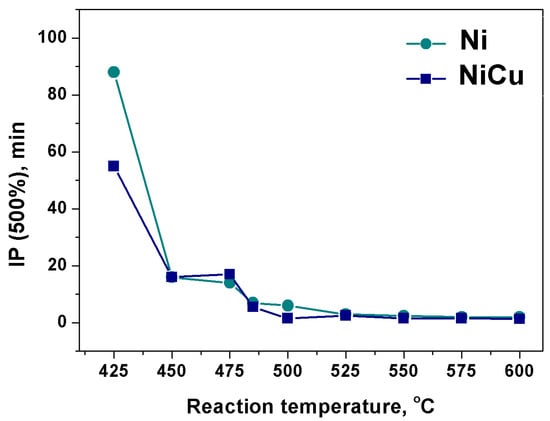
Figure 1.
Diagram of the IP duration (min) dependence on the reaction temperature (°C) for Ni and Ni-Cu at 500% CNF mass gain. Reaction conditions: C2H4/H2/Ar; 30 min.
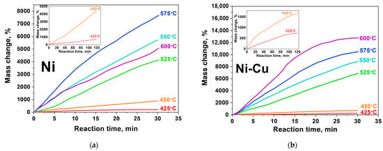
Figure 2.
Kinetic curves of CNF accumulation at various temperatures: (a)—Ni; (b)—Ni-Cu. Reaction conditions: C2H4/H2/Ar, 30 min. Full kinetic curves for T = 425–450 °C (120 min) are inserted in the left corner of the figures.
It is believed that the IP duration reflects the rate of carbon atoms dissolution in the bulk catalyst. Generally, the nature and concentration of the metal M in the Ni-M alloy composition significantly affects IP duration by accelerating or slowing down the process of carbon saturation of the alloy [51]. According to the data obtained, the introduction of 11 at.% copper has almost no effect on the carbon saturation rate, as evidenced by the close values of IP duration for Ni- and Ni-Cu-catalyst.
The kinetic curves of CNF growth for different reaction conditions are shown in Figure 2. It can be seen that the completion of the induction period of the reaction is followed by the phase of carbon nanomaterial active growth (Figure 2, 5–15 min). The rate of carbon product accumulation at this stage is usually characterized by a stable slope of the kinetic curve. Table 1 summarizes the results of CNF accumulation rate calculation during catalytic pyrolysis of ethylene on Ni- and Ni-Cu-catalysts.

Table 1.
Accumulation rate of carbon product (W, %/min) during ethylene decomposition, and carbon yield (YC, g/gcat) depending on catalyst composition and reaction temperature. Reaction mixture: C2H4/H2/Ar.
Comparison of the kinetic curves (Figure 2) and the values presented in Table 1 allows one to establish how the addition of copper to the Ni-catalyst affects the characteristics of the process. The duration of experiments carried out at relatively low temperatures (415–450 °C) was 120 min (Figure 2a,b). It can be seen that the catalytic activity of Ni and Ni-Cu alloy differs markedly within the selected temperature range. In the case of Ni- catalyst at 425 °C, an almost complete absence of catalytic activity is observed (Figure 2a, 425 °C). Further, with increasing temperature one can see a significant increase in the process rate from 9 to 26%/min (Figure 2a, left corner). At the same time, the deactivation stage is not reflected on the presented kinetic curves. Thus, it can be concluded that nickel particles are able to remain catalytically active for a longer time (t > 120 min) at T < 450 °C.
The kinetic curves for CNF growth presented in Figure 3b demonstrate the catalytic ability of Ni-Cu alloy. It is seen that the maximum mass gain for of Ni-Cu alloy at T = 450 °C is 1650% (Figure 2b, left corner), while the similar value for pure nickel was 2.5 times higher—4440% (Figure 2a, left corner). It is also worth noting that, for curves recorded at T = 425 and 450 °C (Figure 2b, left corner), there is a deactivation stage at a time interval of 110–120 min: curves of CNF accumulation come to a plateau, thus indicating the termination of active particles. In this case, the cause of deactivation might be related to secondary disintegration of active particles and their subsequent rapid encapsulation [48,52]. This assumption is confirmed by the TEM data presented below.
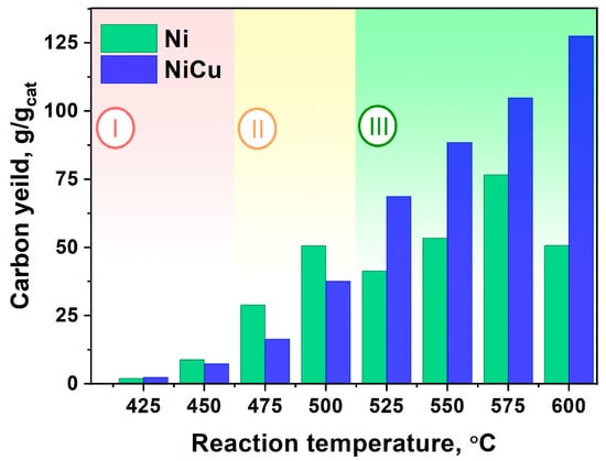
Figure 3.
Dependence of CNF yield (g/gcat) on temperature (425–600 °C) for two series of experiments (Ni and Ni-Cu). Reaction conditions: C2H4/H2/Ar; t = 30 min.
Let us consider the range of higher temperatures (475–525 °C). It can be noted that the curves for this temperature range (Figure 2a,b) have a similar form: at the beginning of the process the slope of the curve is inclined, but it gradually increases towards the end of the considered time period. At the same time, the stage of catalyst deactivation is not observed. Further increase in reaction temperature (550–575 °C) leads to enhancement in CNF accumulation rate. However, a further rise of pyrolysis temperature up to 600 °C leads to a drop in the rate of carbon product accumulation.
Thus, it can be concluded that the optimal temperature for the operation of the Ni-catalyst is in the range from 475 to 550 °C, since after 30 min of reaction the nickel only begins to “accelerate”.
For the Ni-Cu alloy, the dependence of the kinetic curves on temperature looks somewhat simpler: the slope of the curve increases with temperature rise and, accordingly, the CNF accumulation rate increases (Figure 2b). Regardless of the temperature, all experimental curves of CNF growth have a similar shape. The curves slope decreases at the 18th, 15th, and 12th minute of the reaction, respectively (Figure 2b, 550, 575, 600 °C). At the same time, it should be noted that the observed changes can be related to the fact of the carbon sample being stuck in the reactor rather than to the catalyst deactivation itself.
Thus, we can conclude that the growth character of CNF depends on both the composition of the catalyst and the temperature of the process.
Analysis of the results permits one to divide the obtained diagram into three fundamentally different areas (Figure 3). The first low-temperature region (Region I) is characterized by a very low carbon product yield (under 10 g/gcat). In fact, both catalysts in this temperature range are almost inactive which does not allow one to recommend these conditions for the synthesis of CNF. Increasing the reaction temperature to 475–500 °C (Region II) promotes the fast growth of the Ni-catalyst performance, whereas the Ni-Cu alloy activity at the same conditions is 25–50% lower. At the same time, it should be emphasized that the CNF yield (per 30 min of reaction) in this temperature range does not exceed the value of 50 g/gcat. Finally, when the reaction temperature reaches 525 °C and higher (region III), the situation changes substantially. The activity of Ni grows more slowly and even decreases at 600 °C, whereas the Ni-Cu alloy, on the contrary, shows a stable growth of carbon yield. It can be seen that the carbon yield for Ni-Cu catalyst at T = 575–600 °C exceeds the value of 100 g/gcat, which wich is superior to that of pure Ni by 1.5–2.5 times. Thus, in a temperature range of T = 525–600 °C (Region III), the Ni-Cu catalyst exhibits highest effectiveness in CNF production.
It can be concluded that the addition of Cu to the composition of the Ni catalyst leads to an enhancement of its productivity at T > 525 °C in the decomposition of hydrocarbons with the production of CNF. It was also shown in [53,54,55] that the Ni-Cu-catalyst performs more efficiently at high temperatures (500–800 °C) in decomposition of various hydrocarbons.
3.2. Morphology and Structure of the Carbon Product
Figure 4 demonstrates SEM micrographs indicating the secondary structure evolution of the Ni-Cu alloy during its contact with the reaction mixture. It should be noted that the comparison sample (pure Ni) showed the similar behavior. The initial alloy sample is a cluster of flattened, plate-like particles ranging in size from 10 to 100 of microns (Table S1). Figure 4a shows an example of such a particle. This morphology of the original sample is determined by the conditions of its preparation by mechanochemical alloying of Ni and Cu powders [56]. According to XRD analysis data, the phase composition of the initial sample is represented by a solid solution based on the fcc lattice of Ni (Figure S2, Table S2).

Figure 4.
SEM data. (a)—original Ni-Cu alloy; (b)—1 min in C2H4/H2/Ar; (c)—30 min in C2H4/H2/Ar. T = 550 °C. Images (b,c) were taken in the back-reflected electron mode.
As can be seen from Figure 4b, carbon nanostructured material is formed as a result of short contact with the reaction mixture C2H4/H2/Ar. In this case, in the composition of the carbon product it is possible to observe the dispersed metallic alloy fragments formed as a result of large agglomerates disintegration, since it has been shown in our previous studies [34,56]. A further role for the dispersed alloy particles is associated with the catalytic growth of carbon filaments as a result of ethylene pyrolysis. We can see (Figure 4c) that after 30 min of interaction with ethylene, the sample is represented by number of carbon filaments.
Analysis of TEM data for two series of experiments with Ni and Ni-Cu catalysts revealed that in all cases the predominant product is graphite-like carbon nanofibers. Figure 5 shows images of CNF samples produced on pure Ni catalyst at different reaction temperatures.

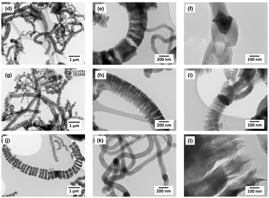
Figure 5.
TEM data for CNF samples obtained on the Ni-catalyst at different temperatures: (a–c)—T = 450 °C; (d–f)—T = 500 °C; (g–i)—T = 550 °C; (j–l)—T = 600 °C. Reaction conditions: C2H4/H2/Ar; t = 30 min.
In spite of insignificant carbon yield at 450 °C (Figure 3), the obtained material consists exclusively of carbon filaments up to 200 nm in diameter (Figure 5a–c). The catalytic particles can have a symmetric shape with a clear faceting (Figure 5c); they carry out the growth of filaments in 2–4 directions (Figure 5b,c). The scattering of carbon filaments by thickness increases with the synthesis temperature (Figure 5d,g). At the same time the fraction of filaments with submicron diameter d > 250 nm. For these CNFs the tendency to form an unusual discrete structure (Figure 5e,h) is obviously expressed, while the filaments with diameter of 100 nm and less are characterized by a continuous packing (Figure 5c,f,k). At 550–600 °C the contribution of thick filaments with a discrete structure to the overall morphology of the product becomes decisive (Figure 5g); the thickness of carbon filaments can reach 1 μm (Figure 5i).
Let’s take a closer look at the secondary structure of segmented carbon filaments resembling “railway crossties” (Figure 5g). The very weak connectivity of individual “segments” that make up the structure of discrete carbon filaments attracts attention (Figure 5j). It should be particularly noted that the detection and subsequent study of such fragile carbon structures becomes possible due to the soft regime of sample preparation for TEM. The stage of destructive ultrasonic treatment of the sample was excluded [57]. As can be seen from the image in Figure 5i, the thickness of the individual weakly bound graphene packages is approximately 100–150 nm. In Figure 6 a scheme explaining a possible mechanism of such filaments formation is proposed.
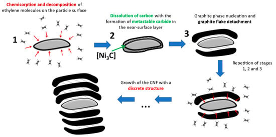
Figure 6.
Presumed growth mechanism of carbon filaments with “railway crossties” structure on large Ni particles (d > 250 nm).
The mechanism of such a secondary CNF structure formation can be explained by a change in the bulk alloy disintegration character. Indeed, with the temperature increase, there is a significant growth of the average size of the active particles on which C2H4 decomposition and filament growth occur simultaneously. The rise of the particle size to 0.5–1 μm causes a significant lengthening of the carbon atoms diffusion path in the particle from its “front” faces to the “back” ones [20]. This probably leads to reconstruction of the mechanism: same facet of a large crystal begins to decompose ethylene molecules and form carbon filaments from carbon atoms dissolved in the near-surface layer simultaneously (functioning in so-called “sponge” mode). Thus, the functions of the active particle surface regularly alternate, which ultimately leads to the formation of the CNF with the observed segmented structure.
As will be shown below, the addition of Cu to the composition of the Ni-catalyst results in significant change in the disintegration character of bulk particles and the subsequent growth of CNF. Figure 7 shows TEM data for CNF patterns obtained as a result of ethylene decomposition on Ni-Cu alloy in the temperature range of 450–600 °C.

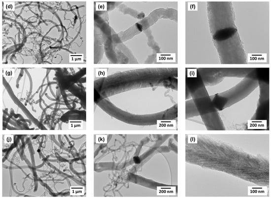
Figure 7.
TEM data for CNF samples obtained on Ni-Cu-catalyst at different temperatures: (a–c)—T = 450 °C; (d–f)—T = 500 °C; (g–i)—T = 550 °C; (j–l)—T = 600 °C. Reaction conditions: C2H4/H2/Ar; t = 30 min.
As in the case of the Ni-catalyst, the carbon product obtained on Ni-Cu alloy is represented exclusively by graphite-like filaments; at the same time, the variation in filament diameter is noticeably wider (Figure 7c,d,j,k). Regardless of thickness, the packing structure of CNF produced on Ni-Cu catalyst is dense, without characteristic segmentation. The large active particles (d > 100 nm) are predominantly symmetrical and catalyze the growth of carbon filaments in two opposite directions (Figure 7c,f,i,k).
It should also be noted that the presence of fine nanofibers with a diameter of 10–50 nm in the composition of the carbon product can probably be attributed to the secondary disintegration of submicron particles formed as a result of the bulk alloy fragmentation. This phenomenon is illustrated in Figure 7k, which shows how a ~200 nm thick carbon filament splits into many thin nanofibers. This morphological feature can be explained by the sudden “explosive” disintegration of the submicron active particle.
Thus, the comparative analysis allows us to conclude that the addition of copper to the nickel-based alloy leads to a noticeable change in the growth pattern of CNF. The presence of copper stabilizes the catalytic activity of nickel in the temperature range of 500–600 °C, not allowing it to undergo rapid deactivation. The growth of carbon product on catalytic particles of Ni-Cu alloy is characterized by the formation of carbon filaments with a denser structure.
3.3. Raman Spectroscopy Data for CNF Samples
The comparison of the Raman spectra for two series of experiment (Ni and Ni-Cu) are presented in Figure 8a,b. A detailed description of the processing of spectra is given in the methodical part 2.4. The principal parameters calculated from spectra are listed below:
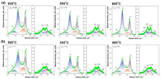
Figure 8.
Raman spectra of CNF samples obtained from Ni (a) and Ni-Cu (b) in the region of first and second order lines. Different colors represent different bands. * to label the different peaks.
- ID/IG
- Amorphous carbon fraction (D3/Gint)
- 2D*/2Dint
The impact of synthesis temperature and metal precursor (Ni and Ni-Cu) on each parameter is presented in Figure 9.
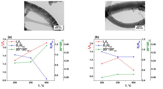
Figure 9.
Dependence of ID/IG, D3/Gint and 2D’*/2D’int on the synthesis temperature for CNF produced on Ni (a) and Ni-Cu (b) catalysts. TEM images for a temperature of 550 °C are shown at the top. * to label the different peaks.
The dimensions of the La in-plane [44] for Ni (Figure 9a) monotonically increase with the temperature increase and lie in the La ~ 15–18 Å range. Thus, the appearance of CNF with discrete structure (Figure 9a, TEM image) is shown in fraction reduction of amorphous carbon (D3/Gint) and growth of integral contribution of line 2D* (HWHM ~ 120 cm−1) of the second order at temperatures above 550 °C.
In contrast, the behavior of CNF produced on Ni-Cu samples is different (Figure 9b). The La in-plane cluster size range for them is smaller than La ~ 13–15 Å. The decrease of the amorphous carbon fraction (D3/Gint) with the temperature increase occurs smoothly. The contribution of the 2D* second order line (HWHM ~ 120 cm−1) practically does not change; it is significantly less than for Ni samples. The observed change in parameters is associated with an increase in temperature and preservation of the CNF packing structure. Thus, the Raman data are consistent with the TEM results.
Next, the textural and macroscopic parameters of the carbon nanomaterials obtained will be discussed in detail.
3.4. Textural and Macroscopic Properties of CNF Samples
One of the important macroscopic characteristics of carbon nanomaterials is the bulk density. It should be emphasized that the carbon product formed on self-dispersing Ni-catalysts is usually characterized by a very low bulk density (ρ < 100 g/L). It is thought to be determined by the growth of carbon filaments occurring in the regime of CE of alloys [33,58,59,60].
Figure 10 shows a comparison of the bulk density values for CNF obtained at different temperatures on Ni and Ni-Cu. It can be seen that the bulk density of the carbon product produced in a wide temperature range T = 475–600 °C does not exceed 60 g/L. In all cases, the values of ρ for Ni-catalyst are higher than values corresponding to Ni-Cu-catalyst. Thus, introduction of Cu into the alloy composition contributes to reduction of CNF bulk density (in the temperature range of 525–600 °C) approximately by 2 times. Following from Figure 10 are the samples obtained with the Ni-Cu alloy. They are characterized by approximately the same bulk density (~25 g/L) when changing the reaction temperature in the range of 525–600 °C.
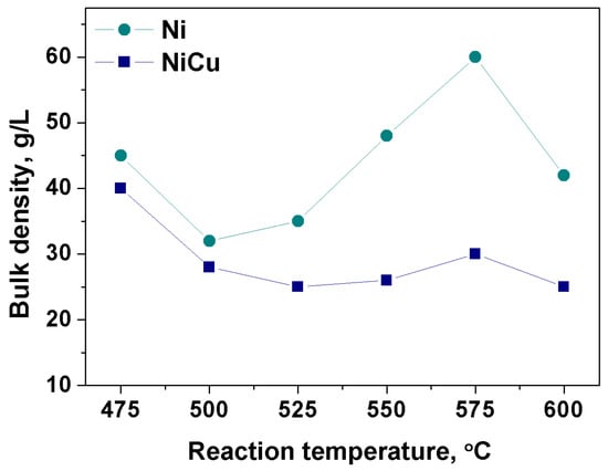
Figure 10.
Dependence of the bulk density (g/L) on the temperature (475–600 °C) for CNF material produced on Ni and Ni-Cu catalysts. Reaction conditions: C2H4/H2/Ar; t = 30 min.
The results show that the CNF synthesized in the Ni-Cu alloy CE regime is very light, even despite the high CNF yield > 100 g/gcat. This fact indicates a minor tendency of the growing carbon filaments to entanglement and formation of agglomerate clumps. The low degree of carbon filaments agglomeration and the light CNF bulk density make it a promising component for introduction into the composite materials as a modifying additive.
Table 2 presents the results of measuring the textural characteristics of the CNF obtained: specific surface area (SSA, m2/g), pore volume (Vp, cm3/g) and average pore diameter (Dav, nm). These values were determined from the analysis of isotherms of nitrogen adsorption/desorption (BET method).

Table 2.
Textural characteristics of CNF samples (BET data).
It is seen that the SSA of CNF samples produced at T < 600 °C varies in the range 110–140 m2/g, regardless of the catalyst composition. At increase in pyrolysis temperature up to 600 °C, introduction of Cu promotes the increase in SSA to 210 m2/g. In contrast, the SSA of the comparison sample (Ni- catalyst) practically does not change (Table 2). The result obtained agrees well with the previously published data for CNF synthesized from applied Ni-Cu/Al2O3 catalysts. A certain jump of SSA values was also observed in the range of 600–700 °C due to CNF structure loosening (so called “feather” filament structure) [60]. Thus, the addition of Cu to the Ni catalyst composition contributes to a significant increase in the specific surface area of the carbon material (by 100 m2/g) at T = 600 °C.
Such a fluffy material with a developed specific surface area can be promising as a modifying additive in various composite materials. For example, the addition of a small amount of CNF to the composition of cement stone can lead to its hardening, increase in crack resistance, etc. [4,5,61,62,63]. CNF have also demonstrated their effectiveness when added to polymeric materials [6,7,64,65,66]. The low bulk density of CNF can facilitate the obtaining of lubricant-based suspensions. Lubricants modified by CNF can subsequently provide less wear of fraction pairs due to the occurrence of carbon-containing protecting film [10,11,67]. Also, high SSA makes it possible to use this material as a carrier for catalysts and sorbents [12,13,14,15,16,17,18,19,68,69,70,71,72].
4. Conclusions
It was revealed that the addition of Cu to the self-dispersing Ni catalyst promotes an increase in its performance in CNF production by 1.5–2.5 times in the temperature range of 525–600 °C. After 30 min of reaction the CNF yield for Ni-Cu-catalyst reaches 100 g/gcat and higher. Despite the high values of the CNF yield, the obtained carbon product is characterized by a very low bulk density (not more than 60 g/L), which further decreases with the addition of Cu to 25–30 g/L. Introduction of Cu also contributes to the increase in the specific surface area of CNF at T = 600 °C from 110 to 210 m2/g.
According to TEM data, for the CNF samples obtained on Ni, the structure is presented mainly as “railway crossties” segmented filaments with a thickness of d > 250 nm. In accordance with the data obtained, a scheme representing the growth mechanism of such filaments with a discrete structure has been proposed. The growth of carbon filaments with the densely packed structure of the graphene layers is characteristic for the CNF samples produced on Ni-Cu alloy. The Raman data are consistent with the TEM results.
Thus, the microdispersed self-dispersing Ni-Cu alloy can be recommended as an effective catalyst for the process of catalytic pyrolysis of light hydrocarbons and targeted production of CNF.
Supplementary Materials
The following supporting information can be downloaded at: https://www.mdpi.com/article/10.3390/c9030077/s1, Figure S1: XRD patterns of the pristine Ni-Cu alloy in different regions of 2Θ: (a)–2Θ = 20–100°; (b)–2Θ = 140–148°; Table S1: Particle size distribution data for Ni-Cu alloy. Diameter of the milling balls = 5 mm, activation time = 5 min; Table S2: Phase compositions and the lattice parameters for the Ni and Ni-Cu samples. XRD data.
Author Contributions
Conceptualization, I.V.M., S.D.A. and A.A.V.; methodology, S.D.A., Y.I.B., V.O.S. and M.N.V.; investigation, S.D.A., M.N.V., V.O.S. and Y.I.B.; writing—original draft preparation, S.D.A.; writing—review and editing, I.V.M. and A.A.V.; visualization, S.D.A.; supervision, A.A.V. and I.V.M.; funding acquisition, I.V.M. All authors have read and agreed to the published version of the manuscript.
Funding
This work was supported by the Ministry of Science and Higher Education of the Russian Federation within the governmental order for Boreskov Institute of Catalysis (project AAAA-A21-121011390054-1). The physicochemical characterization of samples was supported by the Russian Science Foundation (project No. 22-13-00406, https://rscf.ru/en/project/22-13-00406/BIC SB RAS (accessed on 30 March 2023)).
Data Availability Statement
Data are contained within the article.
Acknowledgments
Analysis of the physicochemical properties of the samples was performed using the equipment of the ‘National Center for Catalyst Research’ (Novosibirsk, BIC SB RAS) and Krasnoyarsk regional Center of the Collective Use (KSS SB RAS). The authors are grateful to A.N. Serkova for the performed SEM studies, B.A. Kolesov for the Raman spectra data, to A.B. Ayupov for analyzing samples by low-temperature adsorption/desorption of nitrogen, to Y.V. Shubin for the XRD analysis and to E.I. Belyaeva for the particle distribution analysis.
Conflicts of Interest
The authors declare no conflict of interest.
References
- Ruiz-Cornejo, J.C.; Sebastián, D.; Lázaro, M.J. Synthesis and applications of carbon nanofibers: A review. Rev. Chem. Eng. 2020, 36, 493–511. [Google Scholar] [CrossRef]
- Feng, L.; Xie, N.; Zhong, J. Carbon nanofibers and their composites: A review of synthesizing, properties and applications. Materials 2014, 7, 3919–3945. [Google Scholar] [CrossRef] [PubMed]
- Afzal, M.T.; Khushnood, R.A. Influence of carbon nano fibers (CNF) on the performance of high strength concrete exposed to elevated temperatures. Constr. Build. Mater. 2021, 268, 121108. [Google Scholar] [CrossRef]
- Gao, Y.; Zhu, X.; Corr, D.J.; Konsta-Gdoutos, M.S.; Shah, S.P. Characterization of the interfacial transition zone of CNF-Reinforced cementitious composites. Cem. Concr. Compos. 2019, 99, 130–139. [Google Scholar] [CrossRef]
- Zhu, X.; Gao, Y.; Dai, Z.; Corr, D.J.; Shah, S.P. Effect of interfacial transition zone on the Young’s modulus of carbon nanofiber reinforced cement concrete. Cem. Concr. Res. 2018, 107, 49–63. [Google Scholar] [CrossRef]
- Alam, A.; Zhang, Y.; Kuan, H.-C.; Lee, S.-H.; Ma, J. Polymer composite hydrogels containing carbon nanomaterials—Morphology and mechanical and functional performance. Prog. Polym. Sci. 2018, 77, 1–18. [Google Scholar] [CrossRef]
- Al-Saleh, M.H.; Sundararaj, U. Review of the mechanical properties of carbon nanofiber/polymer composites. Compos. Part A Appl. Sci. Manuf. 2011, 42, 2126–2142. [Google Scholar] [CrossRef]
- Mohamed, A. Chapter Eight—Synthesis, Characterization, and Applications Carbon Nanofibers. In Carbon-Based Nanofillers and Their Rubber Nanocomposites; Yaragalla, S., Mishra, R., Thomas, S., Kalarikkal, N., Maria, H.J., Eds.; Elsevier: Amsterdam, The Netherlands, 2019; pp. 243–257. [Google Scholar]
- Ren, X.; Wang, X.Q.; Sui, G.; Zhong, W.H.; Fuqua, M.A.; Ulven, C.A. Effects of carbon nanofibers on crystalline structures and properties of ultrahigh molecular weight polyethylene blend fabricated using twin-screw extrusion. J. Appl. Polym. Sci. 2007, 107, 2837–2845. [Google Scholar] [CrossRef]
- Furimsky, E. Preface. In Carbon Nanomaterials in Hydrogenation Catalysis; The Royal Society of Chemistry: London, UK, 2019. [Google Scholar]
- Matsui, K.; Lanticse, L.J.; Tanabe, Y.; Yasuda, E.; Endo, M. Stress graphitization of C/C composite reinforced by carbon nanofiber. Carbon 2005, 43, 1577–1579. [Google Scholar] [CrossRef]
- Yap, J.W.; Wang, T.; Cho, H.; Kim, J.-H. Comparison of carbon-nanofiber and carbon-nanotube as conductive additives in Si anodes for high-energy lithium-ion batteries. Electrochim. Acta 2023, 446, 142108. [Google Scholar] [CrossRef]
- Fu, R.; Lu, Y.; Ding, Y.; Li, L.; Ren, Z.; Si, X.; Wu, Q. A novel non-enzymatic glucose electrochemical sensor based on CNF@Ni-Co layered double hydroxide modified glassy carbon electrode. Microchem. J. 2019, 150, 104106. [Google Scholar] [CrossRef]
- Chen, L.; Chen, L.; Ai, Q.; Li, D.; Si, P.; Feng, J.; Zhang, L.; Li, Y.; Lou, J.; Ci, L. Flexible all-solid-state supercapacitors based on freestanding, binder-free carbon nanofibers@polypyrrole@graphene film. Chem. Eng. J. 2018, 334, 184–190. [Google Scholar] [CrossRef]
- Liang, J.-J.; Zhao, Z.-B.; Tang, Y.-C.; Liang, Z.-H.; Sun, L.-L.; Pan, X.; Wang, X.-Z.; Qiu, J.-S. A wearable strain sensor based on carbon derived from linen fabrics. New Carbon Mater. 2020, 35, 522–530. [Google Scholar] [CrossRef]
- Huang, B.; Yue, J.; Wei, Y.; Huang, X.; Tang, X.; Du, Z. Enhanced microwave absorption properties of carbon nanofibers functionalized by FeCo coatings. Appl. Surf. Sci. 2019, 483, 98–105. [Google Scholar] [CrossRef]
- Mishakov, I.V.; Bauman, Y.I.; Brzhezinskaya, M.; Netskina, O.V.; Shubin, Y.V.; Kibis, L.S.; Stoyanovskii, V.O.; Larionov, K.B.; Serkova, A.N.; Vedyagin, A.A. Water purification from chlorobenzenes using heteroatom-functionalized carbon nanofibers produced on self-organizing Ni-Pd catalyst. J. Environ. Chem. Eng. 2022, 10, 107873. [Google Scholar] [CrossRef]
- Schoemaker, S.E.; Welling, T.A.J.; Wezendonk, D.F.L.; Reesink, B.H.; van Bavel, A.P.; de Jongh, P.E. Carbon nanofiber growth from methane over carbon-supported NiCu catalysts: Two temperature regimes. Catal. Today 2023, 418, 114110. [Google Scholar] [CrossRef]
- Timofeeva, M.N.; Matrosova, M.M.; Reshetenko, T.V.; Avdeeva, L.B.; Budneva, A.A.; Ayupov, A.B.; Paukshtis, E.A.; Chuvilin, A.L.; Volodin, A.V.; Likholobov, V.A. Filamentous carbons as a support for heteropoly acid. J. Mol. Catal. A Chem. 2004, 211, 131–137. [Google Scholar] [CrossRef]
- Chesnokov, V.V.; Buyanov, R.A. The formation of carbon filaments upon decomposition of hydrocarbons catalysed by iron subgroup metals and their alloys. Russ. Chem. Rev. 2000, 69, 623. [Google Scholar] [CrossRef]
- Kim, S.-S.; Kim, K.-W.; Ahn, H.-J.; Cho, K.-K. Characterization of graphitic nanofibers synthesized by the CVD method using nickel–copper as a catalyst. J. Alloys Compd. 2008, 449, 274–278. [Google Scholar] [CrossRef]
- Chen, D.; Christensen, K.O.; Ochoa-Fernández, E.; Yu, Z.; Tøtdal, B.; Latorre, N.; Monzón, A.; Holmen, A. Synthesis of carbon nanofibers: Effects of Ni crystal size during methane decomposition. J. Catal. 2005, 229, 82–96. [Google Scholar] [CrossRef]
- Komova, O.V.; Simakov, A.V.; Kovalenko, G.A.; Rudina, N.A.; Chuenko, T.V.; Kulikovskaya, N.A. Formation of a nickel catalyst on the surface of aluminosilicate supports for the synthesis of catalytic fibrous carbon. Kinet. Catal. 2007, 48, 803–811. [Google Scholar] [CrossRef]
- Karimi, S.; Bibak, F.; Meshkani, F.; Rastegarpanah, A.; Deng, J.; Liu, Y.; Dai, H. Promotional roles of second metals in catalyzing methane decomposition over the Ni-based catalysts for hydrogen production: A critical review. Int. J. Hydrogen Energy 2021, 46, 20435–20480. [Google Scholar] [CrossRef]
- Rastegarpanah, A.; Meshkani, M.F.; Rezaei, M. Thermocatalytic decomposition of methane over mesoporous nanocrystalline promoted Ni/MgO·Al2O3 catalysts. Int. J. Hydrogen Energy 2017, 42, 16476–16488. [Google Scholar] [CrossRef]
- Torres, D.; Pinilla, J.; Suelves, I. Co-, Cu- and Fe-Doped Ni/Al2O3 Catalysts for the Catalytic Decomposition of Methane into Hydrogen and Carbon Nanofibers. Catalysts 2018, 8, 300. [Google Scholar] [CrossRef]
- Wang, D.; Zhang, J.; Sun, J.; Gao, W.; Cui, Y. Effect of metal additives on the catalytic performance of Ni/Al2O3 catalyst in thermocatalytic decomposition of methane. Int. J. Hydrogen Energy 2019, 44, 7205–7215. [Google Scholar] [CrossRef]
- Al-Hilfi, S.H.; Derby, B.; Martin, P.A.; Whitehead, J.C. Chemical vapour deposition of graphene on copper–nickel alloys: The simulation of a thermodynamic and kinetic approach. Nanoscale 2020, 12, 15283–15294. [Google Scholar]
- Sridhar, D.; Omanovic, S.; Meunier, J.-L. Direct growth of carbon nanofiber forest on nickel foam without any external catalyst. Diam. Relat. Mater. 2018, 81, 70–76. [Google Scholar] [CrossRef]
- Bauman, Y.I.; Mishakov, I.V.; Vedyagin, A.A.; Serkova, A.N.; Gromov, A.A. Kinetic features of the carbon erosion of a bulk NiCr alloy during the catalytic decomposition of 1,2-dichloroethane. Kinet. Catal. 2017, 58, 448–454. [Google Scholar] [CrossRef]
- Popov, A.A.; Afonnikova, S.D.; Varygin, A.D.; Bauman, Y.I.; Trenikhin, M.V.; Plyusnin, P.E.; Shubin, Y.V.; Vedyagin, A.A.; Mishakov, I.V. Pt1−xNix Alloy Nanoparticles Embedded in Self-Grown Carbon Nanofibers: Synthesis, Properties and Catalytic Activity in HER. Catalysts 2023, 13, 599. [Google Scholar] [CrossRef]
- Roemers-van Beek, J.M.; Wang, Z.J.; Rinaldi, A.; Willinger, M.G.; Lefferts, L. Initiation of carbon nanofiber growth on polycrystalline nickel foam under low ethylene pressure. ChemCatChem 2018, 10, 3107–3114. [Google Scholar] [CrossRef]
- Mishakov, I.V.; Afonnikova, S.D.; Bauman, Y.I.; Shubin, Y.V.; Trenikhin, M.V.; Serkova, A.N.; Vedyagin, A.A. Carbon Erosion of a Bulk Nickel–Copper Alloy as an Effective Tool to Synthesize Carbon Nanofibers from Hydrocarbons. Kinet. Catal. 2022, 63, 97–107. [Google Scholar] [CrossRef]
- Afonnikova, S.D.; Veselov, G.B.; Bauman, Y.I.; Gerasimov, E.Y.; Shubin, Y.V.; Mishakov, I.V.; Vedyagin, A.A. Synthesis of Ni-Cu-CNF Composite Materials via Carbon Erosion of Ni-Cu Bulk Alloys Prepared by Mechanochemical Alloying. J. Compos. Sci. 2023, 7, 238. [Google Scholar] [CrossRef]
- Sunol, J.; Gonzalez, A.; Escoda, L. Comparison of Fe-Ni based alloys prepared by ball milling and rapid solidification. J. Mater. Sci. 2004, 39, 5147–5150. [Google Scholar] [CrossRef]
- Radev, D. Nickel-containing alloys for medical application obtained by methods of mechanochemistry and powder metallurgy. Int. Sch. Res. Not. 2012, 2012, 464089. [Google Scholar] [CrossRef]
- Amrute, A.P.; De Bellis, J.; Felderhoff, M.; Schüth, F. Mechanochemical synthesis of catalytic materials. Chem.—A Eur. J. 2021, 27, 6819–6847. [Google Scholar] [CrossRef] [PubMed]
- Takacs, L. The historical development of mechanochemistry. Chem. Soc. Rev. 2013, 42, 7649–7659. [Google Scholar] [CrossRef] [PubMed]
- Buyanov, R.A.; Molchanov, V.V.; Boldyrev, V.V. Mechanochemical activation as a tool of increasing catalytic activity. Catal. Today 2009, 144, 212–218. [Google Scholar] [CrossRef]
- ICDD. The Powder Diffraction File 2 (PDF2) 2009 Release; International Centre for Diffraction Data: Newtown Square, PA, USA, 2009. [Google Scholar]
- Kraus, W.; Nolze, G. PowderCell—A program to visualize crystal structures, calculate the corresponding powder patterns and refine experimental curves. J. Appl. Cryst. 1996, 29, 301–303. [Google Scholar] [CrossRef]
- Nemanich, R.J.; Solin, S.A. First- and second-order Raman scattering from finite-size crystals of graphite. Phys. Rev. B 1979, 20, 392–401. [Google Scholar] [CrossRef]
- Tuinstra, F.; Koenig, J.L. Raman Spectrum of Graphite. J. Chem. Phys. 2003, 53, 1126–1130. [Google Scholar] [CrossRef]
- Ferrari, A.C.; Robertson, J. Interpretation of Raman spectra of disordered and amorphous carbon. Phys. Rev. B 2000, 61, 14095–14107. [Google Scholar] [CrossRef]
- Wang, Y.; Alsmeyer, D.C.; McCreery, R.L. Raman spectroscopy of carbon materials: Structural basis of observed spectra. Chem. Mater. 1990, 2, 557–563. [Google Scholar] [CrossRef]
- Sadezky, A.; Muckenhuber, H.; Grothe, H.; Niessner, R.; Pöschl, U. Raman microspectroscopy of soot and related carbonaceous materials: Spectral analysis and structural information. Carbon 2005, 43, 1731–1742. [Google Scholar] [CrossRef]
- Mishakov, I.V.; Bauman, Y.I.; Potylitsyna, A.R.; Shubin, Y.V.; Plyusnin, P.E.; Stoyanovskii, V.O.; Vedyagin, A.A. Catalytic Properties of Bulk (1–x)Ni–xW Alloys in the Decomposition of 1,2-Dichloroethane with the Production of Carbon Nanomaterials. Kinet. Catal. 2022, 63, 75–86. [Google Scholar] [CrossRef]
- Henao, W.; Cazaña, F.; Tarifa, P.; Romeo, E.; Latorre, N.; Sebastian, V.; Delgado, J.J.; Monzón, A. Selective synthesis of carbon nanotubes by catalytic decomposition of methane using Co-Cu/cellulose derived carbon catalysts: A comprehensive kinetic study. Chem. Eng. J. 2021, 404, 126103. [Google Scholar] [CrossRef]
- Inaba, M.; Zhang, Z.; Matsuoka, K.; Soneda, Y. Effect of coexistence of siloxane on production of hydrogen and nanocarbon by methane decomposition using Fe catalyst. Int. J. Hydrogen Energy 2021, 46, 11556–11563. [Google Scholar] [CrossRef]
- Lim, X.-X.; Low, S.-C.; Oh, W.-D. A critical review of heterogeneous catalyst design for carbon nanotubes synthesis: Functionalities, performances, and prospects. Fuel Process. Technol. 2023, 241, 107624. [Google Scholar] [CrossRef]
- Potylitsyna, A.R.; Rudneva, Y.V.; Bauman, Y.I.; Plyusnin, P.E.; Stoyanovskii, V.O.; Gerasimov, E.Y.; Vedyagin, A.A.; Shubin, Y.V.; Mishakov, I.V. Efficient Production of Segmented Carbon Nanofibers via Catalytic Decomposition of Trichloroethylene over Ni-W Catalyst. Materials 2023, 16, 845. [Google Scholar] [CrossRef]
- Chen, X.; Pang, X.; Fauteux-Lefebvre, C. The base versus tip growth mode of carbon nanotubes by catalytic hydrocarbon cracking: Review, challenges and opportunities. Carbon Trends 2023, 12, 100273. [Google Scholar] [CrossRef]
- Torres, D.; Pinilla, J.L.; Suelves, I. Non-oxidative decomposition of propane: Ni-Cu/Al2O3 catalyst for the production of CO2-free hydrogen and high-value carbon nanofibers. J. Environ. Chem. Eng. 2021, 9, 105022. [Google Scholar] [CrossRef]
- Aboul-Enein, A.A.; Awadallah, A.E. Production of nanostructure carbon materials via non-oxidative thermal degradation of real polypropylene waste plastic using La2O3 supported Ni and Ni–Cu catalysts. Polym. Degrad. Stab. 2019, 167, 157–169. [Google Scholar] [CrossRef]
- Zheng, Y.; Wang, J.; Liu, C.; Lu, Y.; Lin, X.; Li, W.; Zheng, Z. Efficient and stable Ni-Cu catalysts for ex situ catalytic pyrolysis vapor upgrading of oleic acid into hydrocarbon: Effect of catalyst support, process parameters and Ni-to-Cu mixed ratio. Renew. Energy 2020, 154, 797–812. [Google Scholar] [CrossRef]
- Afonnikova, S.D.; Mishakov, I.V.; Bauman, Y.I.; Trenikhin, M.V.; Shubin, Y.V.; Serkova, A.N.; Vedyagin, A.A. Preparation of Ni–Cu Catalyst for Carbon Nanofiber Production by the Mechanochemical Route. Top. Catal. 2023, 66, 393–404. [Google Scholar] [CrossRef]
- Bauman, Y.I.; Shorstkaya, Y.V.; Mishakov, I.V.; Plyusnin, P.E.; Shubin, Y.V.; Korneev, D.V.; Stoyanovskii, V.O.; Vedyagin, A.A. Catalytic conversion of 1,2-dichloroethane over Ni-Pd system into filamentous carbon material. Catal. Today 2017, 293–294, 23–32. [Google Scholar] [CrossRef]
- Bauman, Y.I.; Lysakova, A.S.; Rudnev, A.V.; Mishakov, I.V.; Shubin, Y.V.; Vedyagin, A.A.; Buyanov, R.A. Synthesis of nanostructured carbon fibers from chlorohydrocarbons over Bulk Ni-Cr Alloys. Nanotechnol. Russ. 2014, 9, 380–385. [Google Scholar] [CrossRef]
- Acauan, L.H.; Kaiser, A.L.; Wardle, B.L. Direct synthesis of carbon nanomaterials via surface activation of bulk copper. Carbon 2021, 177, 1–10. [Google Scholar] [CrossRef]
- Jarrah, N.A.; Li, F.; van Ommen, J.G.; Lefferts, L. Immobilization of a layer of carbonanofibres (CNFs) on Ni foam: A new structured catalyst support. J. Mater. Chem. 2005, 15, 1946–1953. [Google Scholar] [CrossRef]
- Yang, H.; Wang, D.; Yu, H. Test and Detection of Antifreezing and Anticorrosion Performance of Carbon Nanofiber Bridge Concrete. Int. J. Anal. Chem. 2022, 2022, 4055128. [Google Scholar]
- Liu, T. Application of Carbon Nanofiber-Modified Concrete in Industrial Building Design. Int. J. Anal. Chem. 2023, 2023, 2587551. [Google Scholar] [CrossRef]
- Wang, Z.; Xu, J.; Nie, L.; Xia, W.; Huang, Z.; Meng, X. Research on Dynamic Splitting Tensile Mechanical Properties of Carbon Nanofibers Reinforced Concrete. IOP Conf. Ser. Earth Environ. Sci. 2020, 567, 012038. [Google Scholar] [CrossRef]
- Yadav, D.; Amini, F.; Ehrmann, A. Recent advances in carbon nanofibers and their applications—A review. Eur. Polym. J. 2020, 138, 109963. [Google Scholar] [CrossRef]
- Hammel, E.; Tang, X.; Trampert, M.; Schmitt, T.; Mauthner, K.; Eder, A.; Pötschke, P. Carbon nanofibers for composite applications. Carbon 2004, 42, 1153–1158. [Google Scholar]
- Loganathan, N.N.; Perumal, V.; Pandian, B.R.; Atchudan, R.; Edison, T.N.J.I.; Ovinis, M. Recent studies on polymeric materials for supercapacitor development. J. Energy Storage 2022, 49, 104149. [Google Scholar]
- Xia, R.; Lou, D.; Younes, H.; Haiston, J.; Chen, H.; Hong, H. Synergistic effect of hexagonal boron nitride and carbon nanofibers on tribological behavior of nanolubricant. Tribol. Int. 2023, 177, 107957. [Google Scholar] [CrossRef]
- Xie, Y.; Su, Y.; Wang, P.; Zhang, S.; Xiong, Y. In-situ catalytic conversion of tar from biomass gasification over carbon nanofibers-supported Fe-Ni bimetallic catalysts. Fuel Process. Technol. 2018, 182, 77–87. [Google Scholar] [CrossRef]
- Gusain, R.; Kumar, N.; Ray, S.S. Recent advances in carbon nanomaterial-based adsorbents for water purification. Coord. Chem. Rev. 2020, 405, 213111. [Google Scholar] [CrossRef]
- Wang, J.; Zhang, S.; Su, Y.; Zhu, S. Construction of Fe embedded graphene nanoshell/carbon nanofibers catalyst for catalytic cracking of biomass tar: Effect of CO2 etching. Fuel 2021, 305, 121552. [Google Scholar] [CrossRef]
- Nair, K.G.; Ramakrishnan, V.; Unnathpadi, R.; Karuppanan, K.K.; Pullithadathil, B. Unraveling hydrogen adsorption kinetics of bimetallic Au–Pt nanoisland-functionalized carbon nanofibers for room-temperature gas sensor applications. J. Phys. Chem. C 2020, 124, 7144–7155. [Google Scholar]
- Díaz, E.; Ordóñez, S.; Vega, A. Adsorption of volatile organic compounds onto carbon nanotubes, carbon nanofibers, and high-surface-area graphites. J. Colloid Interface Sci. 2007, 305, 7–16. [Google Scholar] [CrossRef]
Disclaimer/Publisher’s Note: The statements, opinions and data contained in all publications are solely those of the individual author(s) and contributor(s) and not of MDPI and/or the editor(s). MDPI and/or the editor(s) disclaim responsibility for any injury to people or property resulting from any ideas, methods, instructions or products referred to in the content. |
© 2023 by the authors. Licensee MDPI, Basel, Switzerland. This article is an open access article distributed under the terms and conditions of the Creative Commons Attribution (CC BY) license (https://creativecommons.org/licenses/by/4.0/).