
Power Generation Characteristics of Polymer Electrolyte Fuel Cells Using Carbon Nanowalls as Catalyst Support Material


Abstract
1. Introduction
2. Materials and Methods
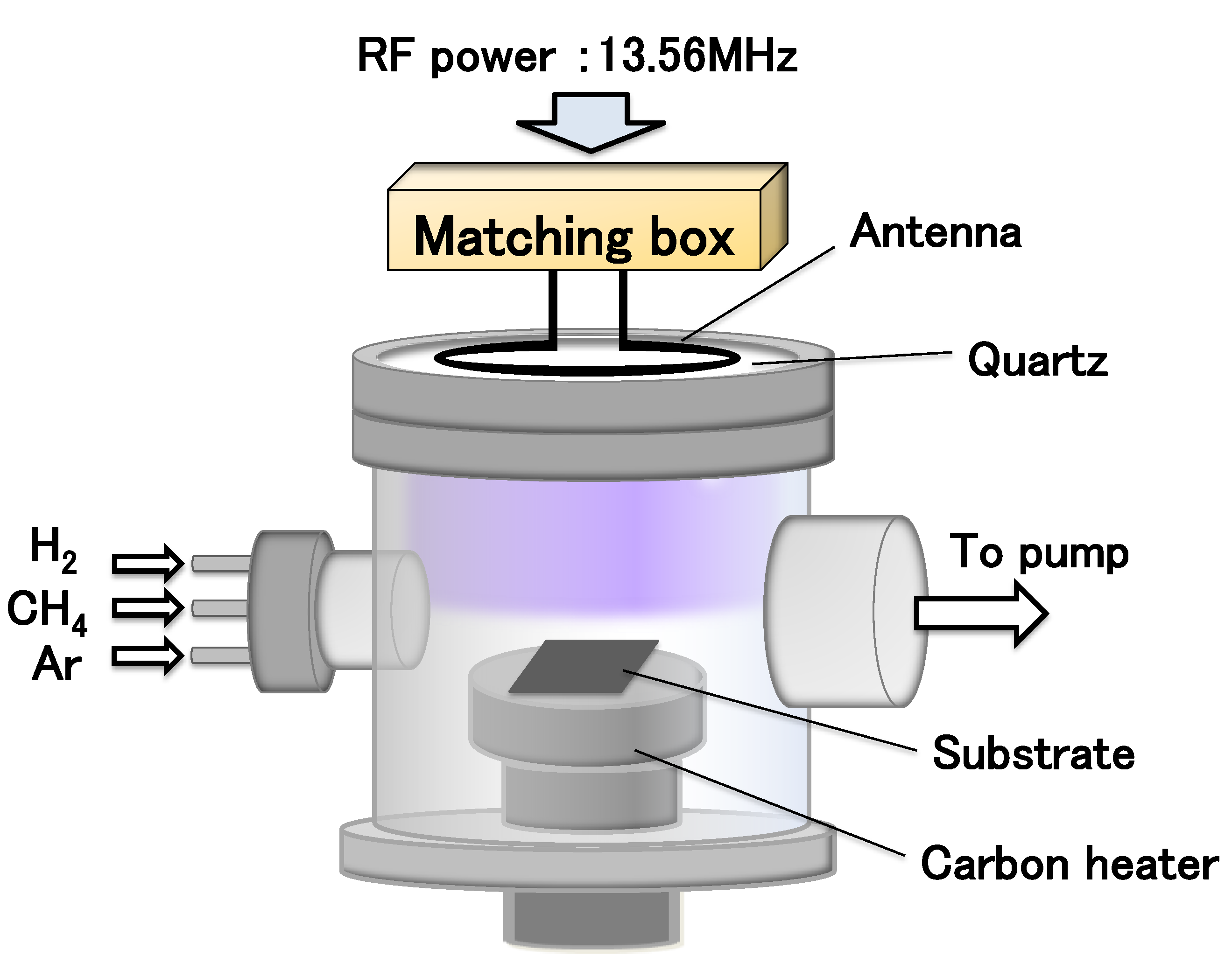
2.1. Plasma-Enhanced Chemical Vapor Deposition for CNW Growth
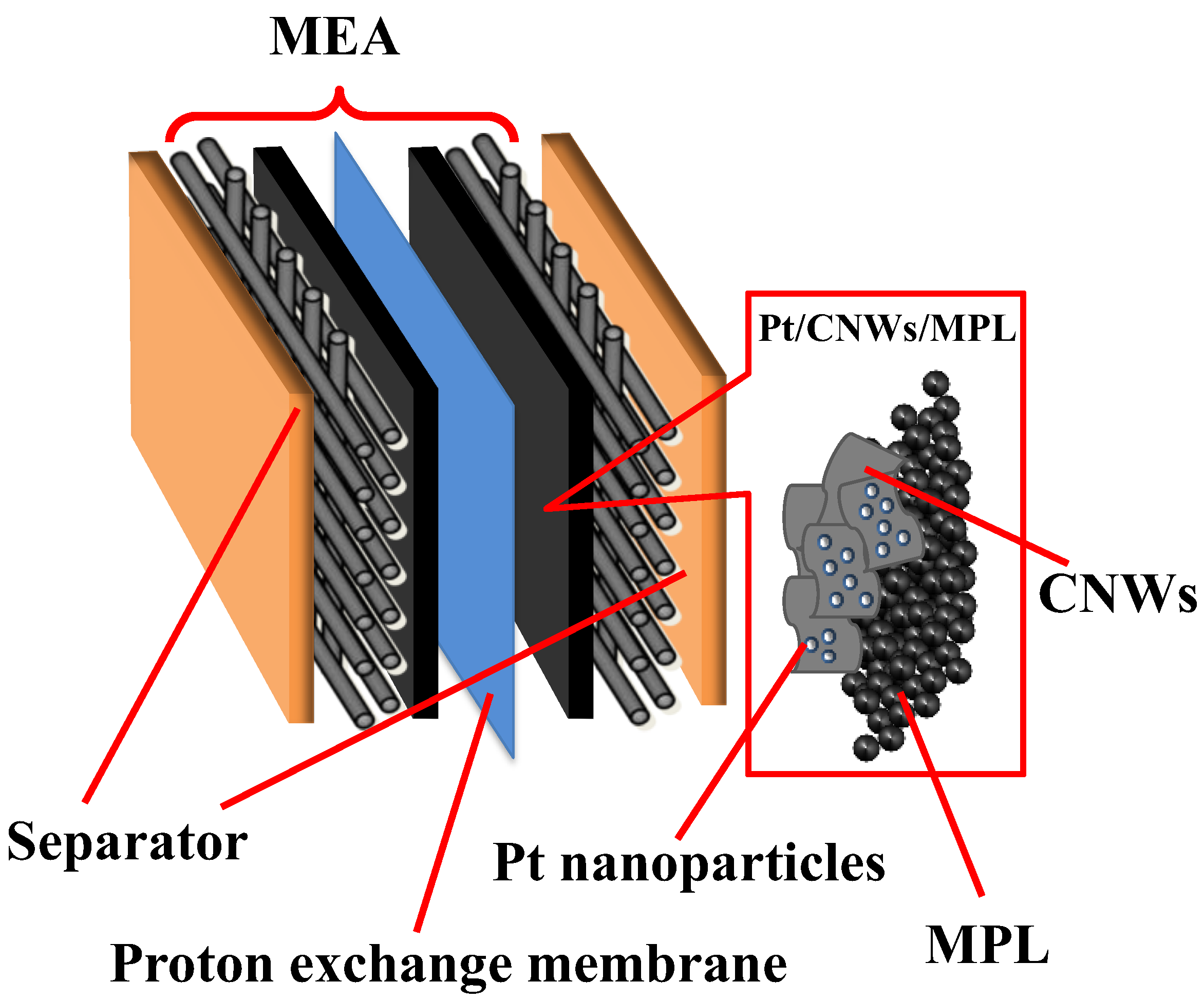
2.2. Structure of a Single PEFC Using CNWs
3. Results and Discussion
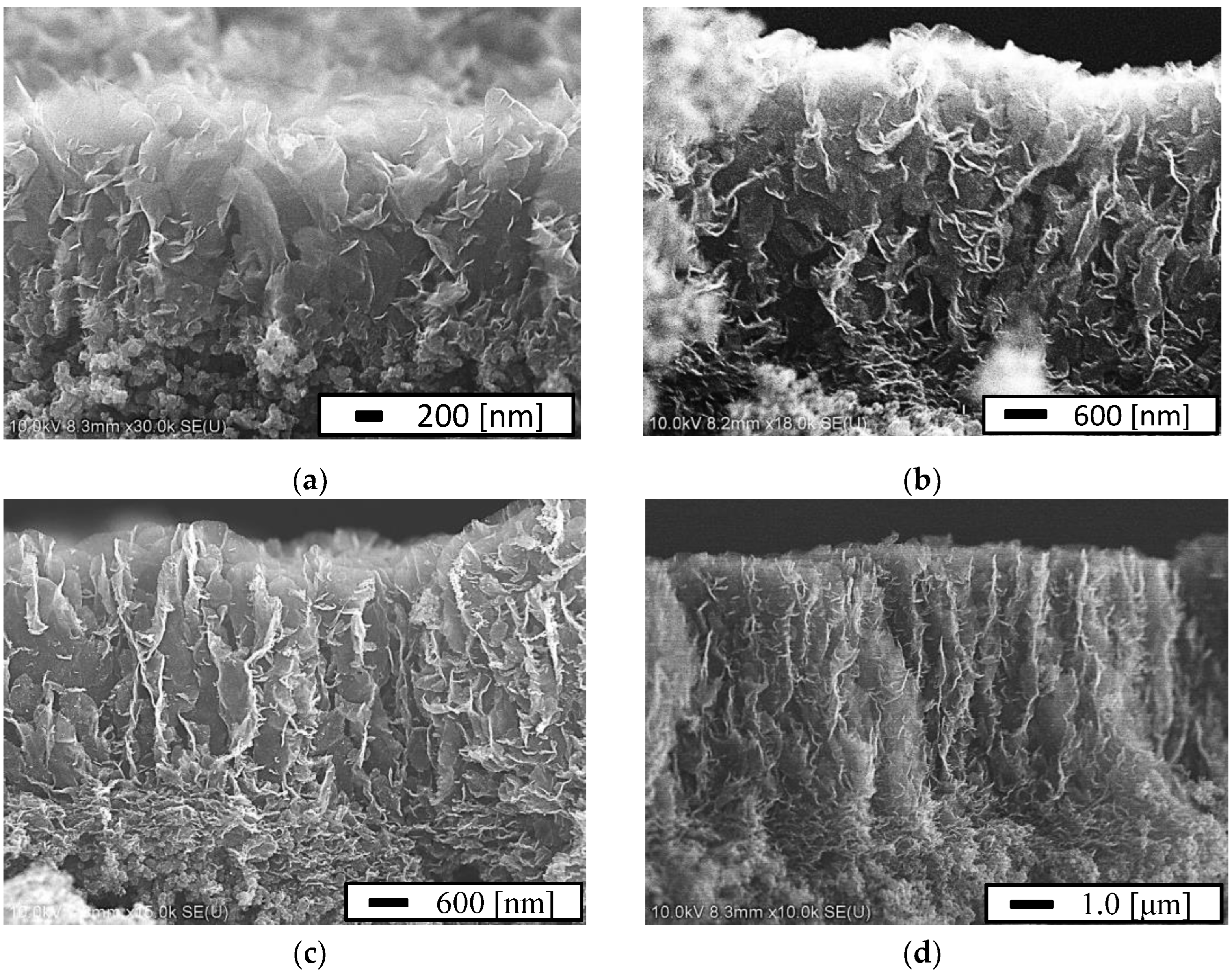
3.1. CNWs on MPL/CP
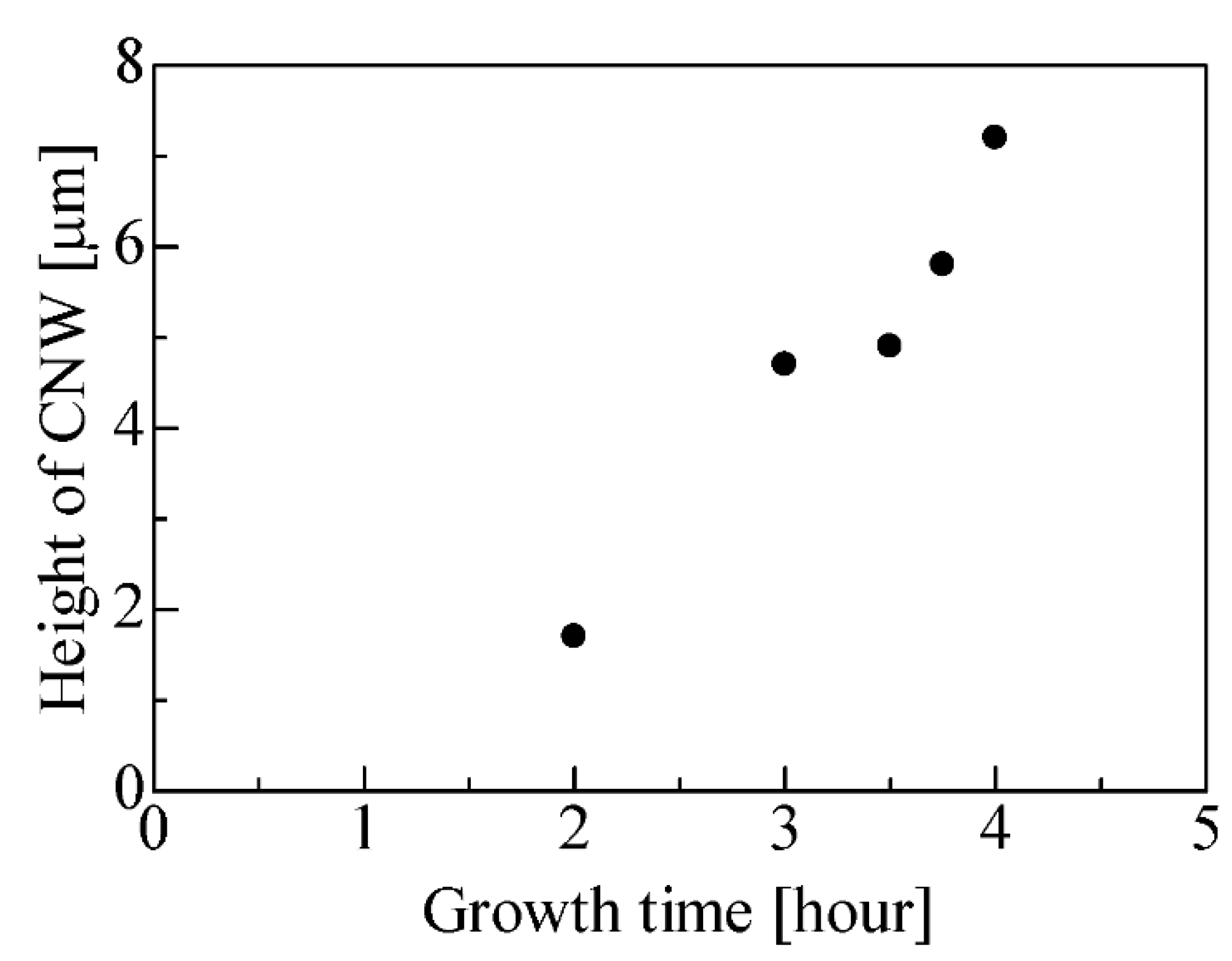
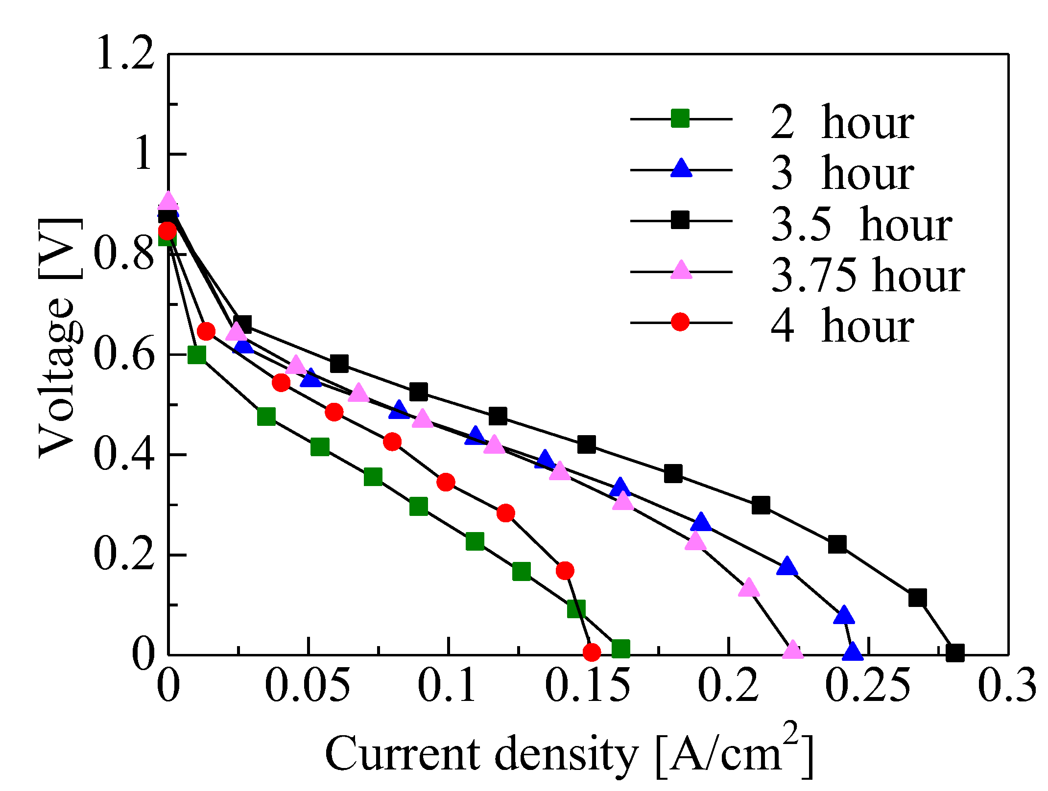
3.2. Relationship between CNW Height and Power Generation Characteristics
3.3. Relationship between CNW Gap Area and Power Generation Characteristics
4. Conclusions
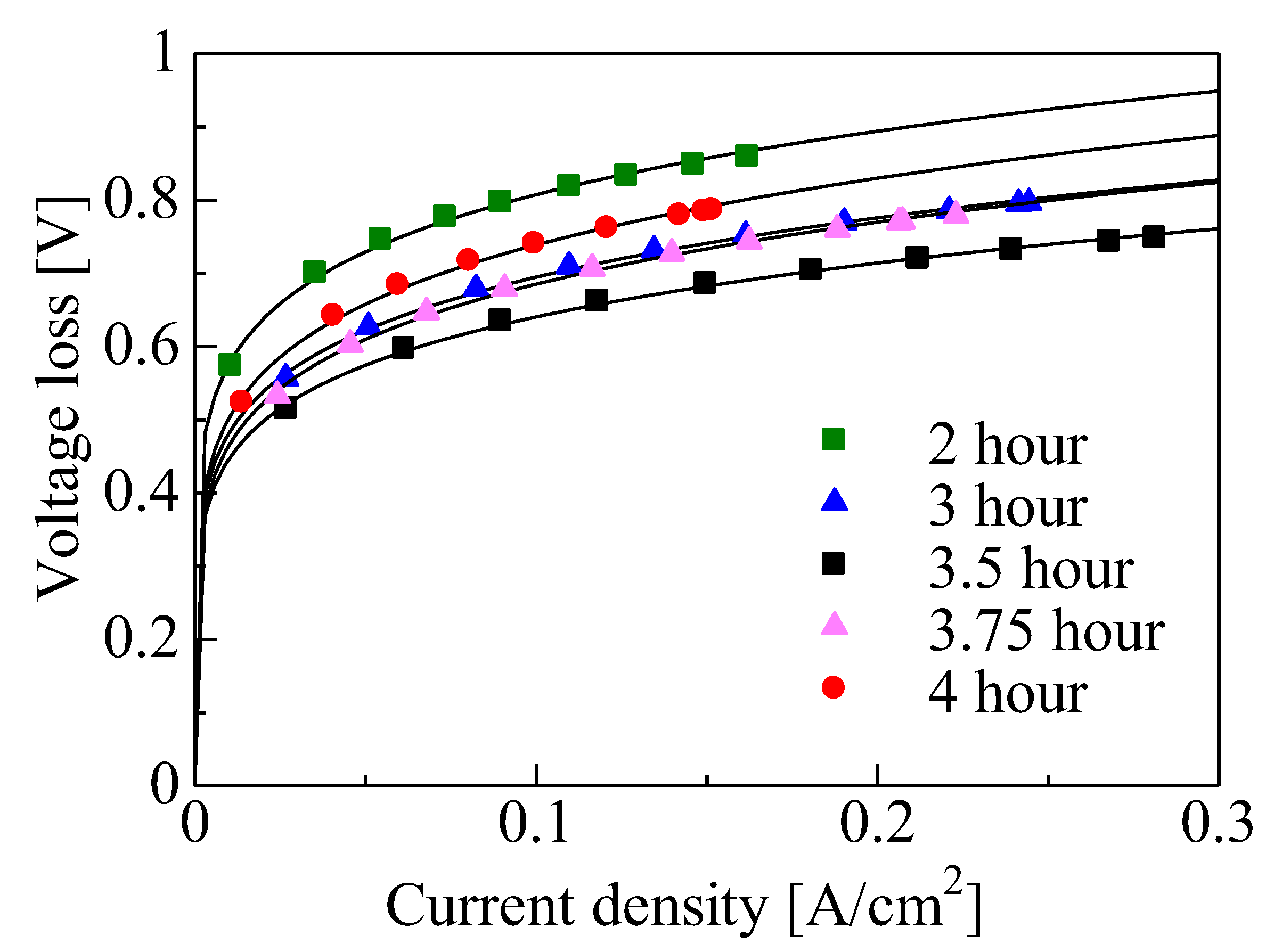
- An increase in the height of the CNWs increased the three-phase interface area with a reduction in the loss due to activated polarization.
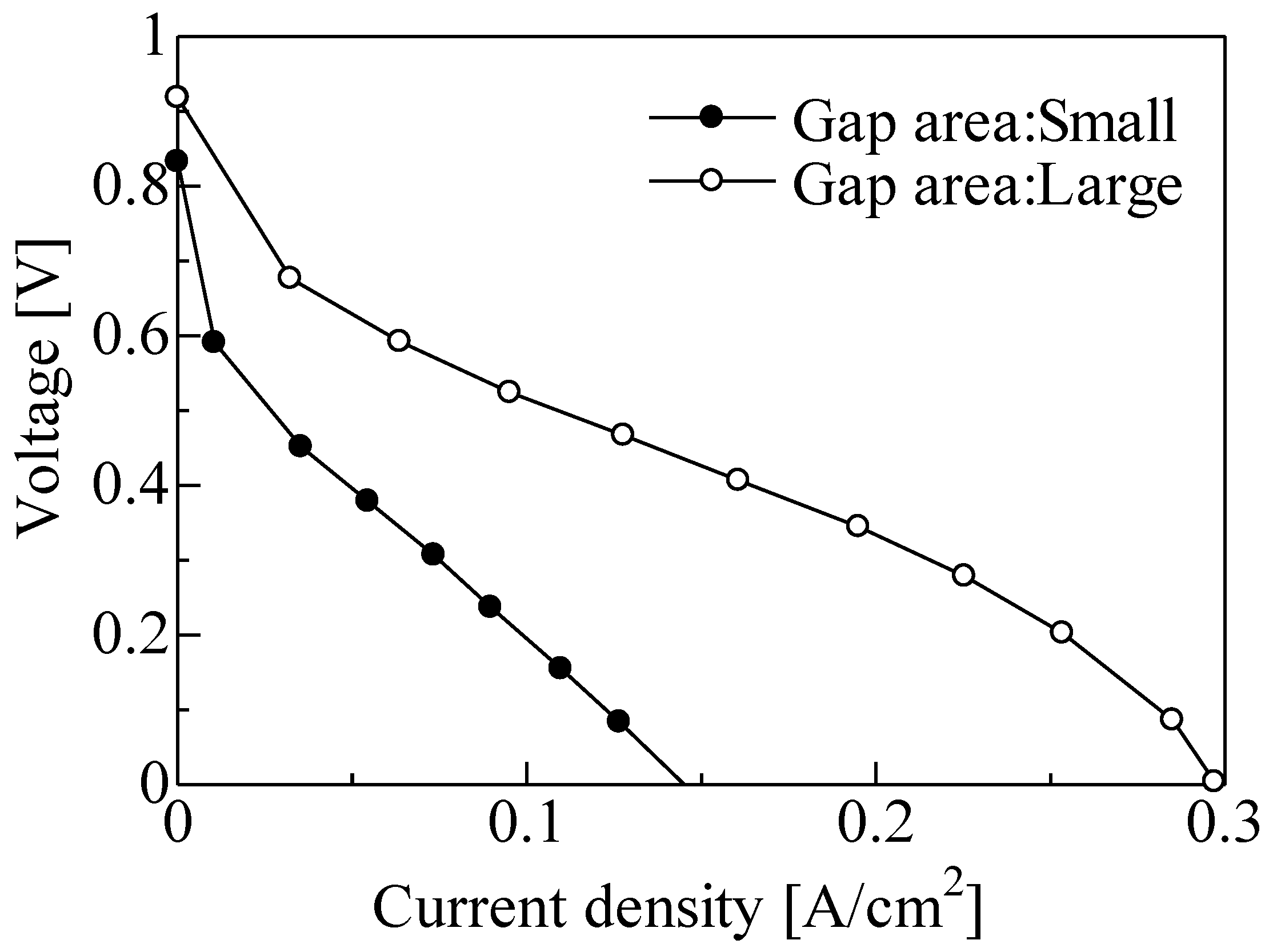
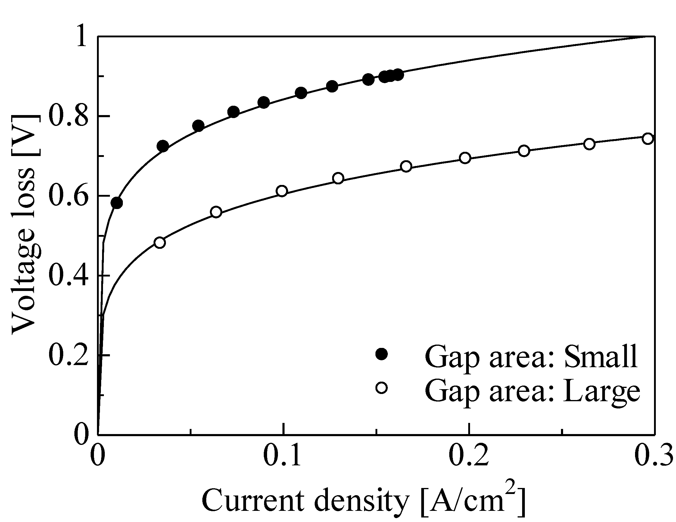
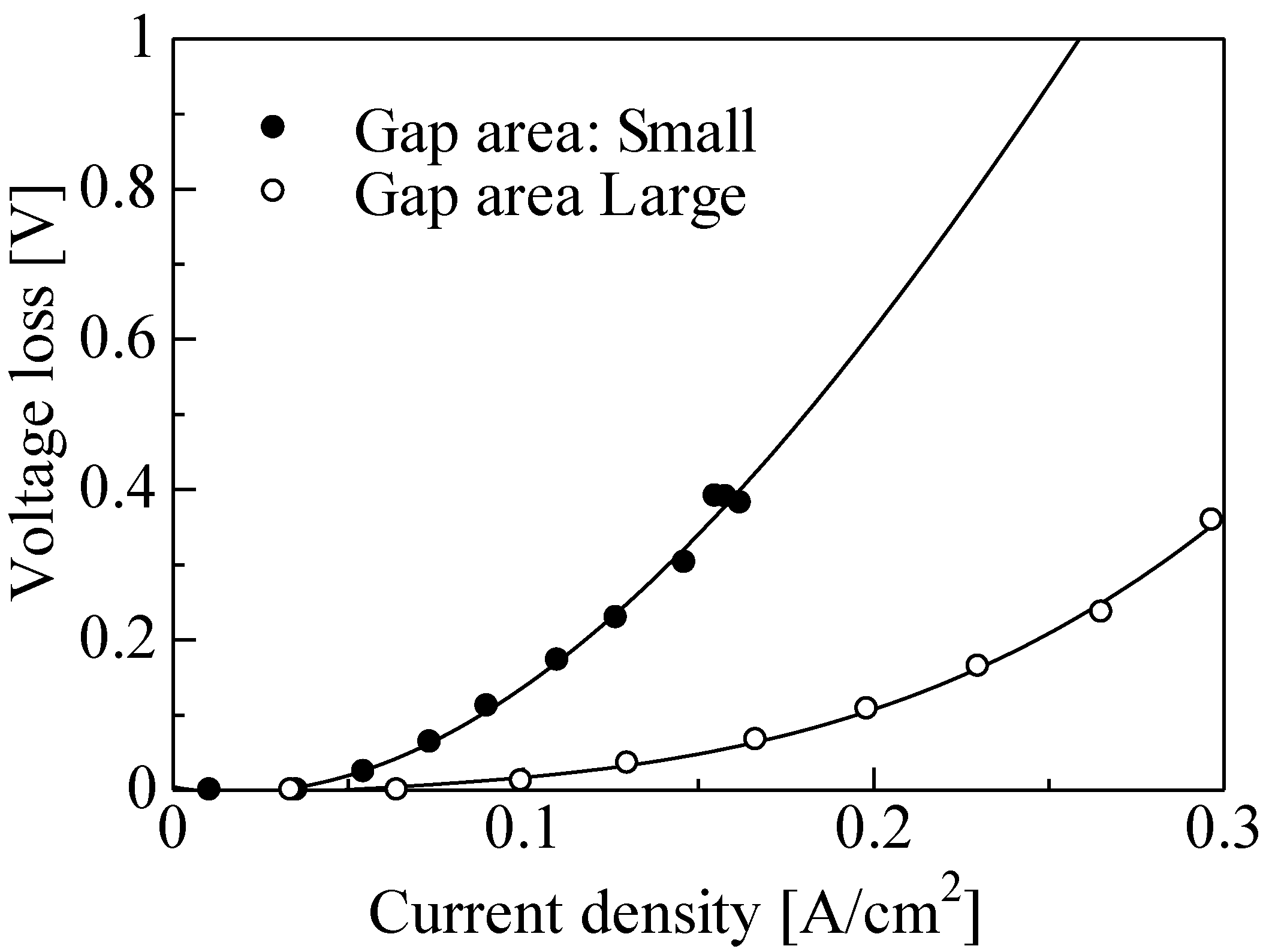
- An increase in the gap area of the CNWs resulted in improvements due to increases in fuel gas diffusion and water discharge, and the loss due to diffusion polarization was reduced.
- The secondary growth of the CNWs caused a reduction in the three-phase interface area due to platinum aggregation, impedance of the supply of ionomer dispersion solution to the bottom of CNWs, and inhibited fuel gas and water diffusion, which led to the loss of activated and diffuse polarizations.
Author Contributions
Funding
Institutional Review Board Statement
Informed Consent Statement
Data Availability Statement
Conflicts of Interest
References
- Clingerman, M.L.; Weber, E.H.; King, J.A.; Schulz, K.H. Synergistic effect of carbon fillers in electrically conductive nylon 6,6 and polycarbonate based resins. Polym. Compos. 2002, 23, 911–924. [Google Scholar] [CrossRef]
- Rimbu, G.A.; Jackson, C.L.; Scott, K. Platinum/carbon/polyaniline based nanocomposites as catalysts for fuel cell technology. J. Optoelectron. Adv. Mater. 2006, 8, 611–616. [Google Scholar]
- Tang., S.; Sun, G.; Qi, J.; Sun, S.; Guo, J.; Xin, Q. Review of new carbon materials as catalyst supports in direct alcohol fuel cells. Chin. J. Catal. 2010, 3, 12–17. [Google Scholar] [CrossRef]
- Lavacchi, A.; Miller, H.; Vizza., F. Nanostructure Science and Technology; Springer: New York, NY, USA, 2013. [Google Scholar]
- Celorrio, V.; Flórez-Montaño, J.; Moliner, R.; Pastor, E.; Lázaro, M.J. Fuel cell performance of Pt electrocatalysts supported on carbon nanocoils. Int. J. Hydrogen Energy. 2014, 39, 5371–5377. [Google Scholar] [CrossRef]
- Kaluža, L.; Larsen, M.J.; Zdražil, M.; Gulková, D.; Vít, Z.; Šolcová, O.; Soukup, K.; Koštejn, M.; Bonde, J.L.; Maixnerová, L.; et al. Highly loaded carbon black supported Pt catalysts for fuel cells. Catal. Today 2015, 256, 375–383. [Google Scholar] [CrossRef]
- Fujii, K.; Ito, M.; Sato, Y.; Takenaka, S.; Kishida, M. Performance and durability of carbon black-supported Pd catalyst covered with silica layers in membrane electrode assemblies of proton exchange membrane fuel cells. J. Power Sources 2015, 279, 100–106. [Google Scholar] [CrossRef]
- Lee, W.H.; Seo, J.; Lee, T.; Kim, H. Preparation of a self-assembled organosilane coating on carbon black as a catalyst support in polymer electrolyte membrane fuel cells. J. Power Sources 2015, 274, 1140–1146. [Google Scholar] [CrossRef]
- Li, M.; Wu, X.; Zeng, J.; Hou, Z.; Liao, S. Heteroatom doped carbon nanofibers synthesized by chemical vapor deposition as platinum electrocatalyst supports for polymer electrolyte membrane fuel cells. Electrochim. Acta 2015, 182, 351–360. [Google Scholar] [CrossRef]
- Geraldes, A.N.; Furtunato da Silva, D.; Martins da Silva, J.C.; Antonio de Sá, O.; Spinacé, E.V.; Neto, A.O.; Coelho dos Santos, M. Palladium and palladium—Tin supported on multi wall carbon nanotubes or carbon for alkaline direct ethanol fuel cell. J. Power Sources. 2015, 275, 189–199. [Google Scholar] [CrossRef]
- Zhou, K.; Li, T.; Han, Y.; Wang, J.; Chen, J.; Wang, K. Optimizing the hydrophobicity of GDL to improve the fuel cell performance. RSC Adv. 2021, 11, 2010. [Google Scholar] [CrossRef]
- Quan, D.L.; Le, P.H. Enhanced methanol oxidation activity of PtRu/C100−xMWCNTsx (x = 0–100 wt.%) by controlling the composition of C-MWCNTs support. Coatings 2021, 11, 571. [Google Scholar] [CrossRef]
- Antolini, E. Carbon supports for low-temperature fuel cell catalysts. Appl. Catal. B Environ. 2009, 88, 1–24. [Google Scholar] [CrossRef]
- Liu, H.-J.; Cui, W.-J.; Jin, L.-H.; Wang, C.-X.; Xia, Y.-Y. Preparation of three-dimensional ordered mesoporous carbon sphere arrays by a two-step templating route and their application for supercapacitors. J. Mater. Chem. 2009, 19, 3661–3667. [Google Scholar] [CrossRef]
- Tang, Z.-H.; He, X.; Song, Y.; Liu, L.; Guo, Q.-G.; Yang, J.-H. Properties of mesoporous carbons prepared from different carbon precursors using nanosize silica as a template. N. Carbon Mater. 2010, 25, 465–469. [Google Scholar] [CrossRef]
- Li, Y.; Fu, Z.-Y.; Su, B.-L. Hierarchically structured porous materials for energy conversion and storage. Adv. Funct. Mater. 2012, 22, 4634–4667. [Google Scholar] [CrossRef]
- Kuppan, B.; Selvam, P. Platinum-supported mesoporous carbon (Pt/CMK-3) as anodic catalyst for direct methanol fuel cell applications: The effect of preparation and deposition methods. Prog. Nat. Sci. Mater. Int. 2012, 22, 616–623. [Google Scholar] [CrossRef][Green Version]
- Bruno, M.M.; Viva, F.A.; Petruccelli, M.A.; Corti, H.R. Platinum supported on mesoporous carbon as cathode catalyst for direct methanol fuel cells. J. Power Sources 2015, 278, 458–463. [Google Scholar] [CrossRef]
- Hung, C.-T.; Liou, Z.-H.; Veerakumar, P.; Wu, P.-H.; Liu, T.-C.; Liu, S.-B. Ordered mesoporous carbon supported bifunctional PtM (M = Ru, Fe, Mo) electrocatalysts for a fuel cell anode. Chin. J. Catal. 2016, 37, 43–53. [Google Scholar] [CrossRef]
- Knupp, S.L.; Li, W.; Paschos, O.; Murray, T.M.; Snyder, J.; Haldar, P. The effect of experimental parameters on the synthesis of carbon nanotube/nanofiber supported platinum by polyol processing techniques. Carbon 2008, 46, 1276–1284. [Google Scholar] [CrossRef]
- Monthioux, M. Carbon Meta-Nanotubes: Synthesis, Properties and Applications; Wiley: Hoboken, NJ, USA, 2011. [Google Scholar]
- Rahsepar, M.; Pakshir, M.; Nikolaev, P.; Piao, Y.; Kim, H. A combined physicochemical and electrocatalytic study of microwave synthesized tungsten mono-carbide nanoparticles on multiwalled carbon nanotubes as a co-catalyst for a proton-exchange membrane fuel cell. Int. J. Hydrogen Energy 2014, 39, 15706–15717. [Google Scholar] [CrossRef]
- Chiang, Y.-C.; Hsieh, M.-K.; Hsu, H.-H. The effect of carbon supports on the performance of platinum/carbon nanotubes for proton exchange membrane fuel cells. Thin Solid Film. 2014, 570, 221–229. [Google Scholar] [CrossRef]
- Weng, B.; Xu, F.; Wu, Z.; Li, Z. Hydrogen generation from LiBH4 solution catalyzed by multiwalled carbon nanotubes supported Co–B nanocatalysts for a portable micro proton exchange membrane fuel cell application. Int. J. Hydrogen Energy. 2014, 39, 14942–14948. [Google Scholar] [CrossRef]
- Jin, H.; Zhu, L.; Bing, N.; Wang, L.; Wang, L. No cytotoxic nitrogen-doped carbon nanotubes as efficient metal-free electrocatalyst for oxygen reduction in fuel cells. Solid State Sci. 2014, 30, 21–25. [Google Scholar] [CrossRef]
- Kitahara, T.; Nakajima, H.; Okamura, K. Gas diffusion layers coated with a microporous layer containing hydrophilic carbon nanotubes for performance enhancement of polymer electrolyte fuel cells under both low and high humidity conditions. J. Power Sources 2015, 283, 115–124. [Google Scholar] [CrossRef]
- Ortiz-Herrera, J.C.; Cruz-Martínez, H.; Solorza-Feria, O.; Medina, D.I. Recent progress in carbon nanotubes support materials for Pt-based cathode catalysts in PEM fuel cells. Int. J. Hydrogen Energy 2022. (In Press) [CrossRef]
- Nasrabadi, M.K.; Ebrahimi-Moghadam, A.; Kumar, R.; Nabipour, N. Electrochemical performance improvement of the catalyst of the methanol microfuel cell using carbon nanotubes. Int. J. Chem. Eng. 2021, 2021, 8894768. [Google Scholar] [CrossRef]
- Kelly, B.T. Physics of Graphite; Applied Science Publishers: London, UK, 1981; p. 291. [Google Scholar]
- Galeano, C.; Meier, J.C.; Peinecke, V.; Bongard, H.; Katsounaros, I.; Topalov, A.A.; Lu, A.; Mayrhofer, K.J.; Schüth, F. Toward highly stable electrocatalysts via nanoparticle pore confinement. J. Am. Chem. Soc. 2012, 134, 20457–20465. [Google Scholar] [CrossRef]
- Vivekananthan, J.; Masa, J.; Chen, P.; Xie, K.; Muhler, M.; Schuhmann, W. Nitrogen-doped carbon cloth as a stable self-supported cathode catalyst for air/H2-breathing alkaline fuel cells. Electrochim. Acta 2015, 182, 312–319. [Google Scholar] [CrossRef]
- Jha, N.; Jafri, R.I.; Rajalakshmi, N.; Ramaprabhu, S. Graphene-multi walled carbon nanotube hybrid electrocatalyst support material for direct methanol fuel cell. Int. J. Hydrogen Energy 2011, 36, 7284–7290. [Google Scholar] [CrossRef]
- Lee, J.; Kim, K.; Park, W.I.; Kim, B.-H.; Park, J.H.; Kim, T.-H. Uniform graphene quantum dots patterned from self-assembled silica nanodots. Nano Lett. 2012, 12, 6078–6083. [Google Scholar] [CrossRef]
- Zhang, X.; Yuan, W.; Duan, J.; Zhang, Y.; Liu, X. Graphene nanosheets modified by nitrogen-doped carbon layer to support Pt nanoparticles for direct methanol fuel cell. Microelectron. Eng. 2015, 141, 234–237. [Google Scholar] [CrossRef]
- Li, L.; Hu, L.; Li, J.; Wei, Z. Enhanced stability of Pt nanoparticle electrocatalysts for fuel cells. Nano Res. 2015, 8, 418–440. [Google Scholar] [CrossRef]
- Yang, H.N.; Lee, D.C.; Park, K.W.; Kim, W.J. Platinum—Boron doped grapheme intercalated by carbon black for cathode catalyst in proton exchange membrane fuel cell. Energy 2015, 89, 500–510. [Google Scholar] [CrossRef]
- Song, C.; Gui, Y.; Xing, X.; Zhang, W. Well-dispersed chromium oxide decorated reduced graphene oxide hybrids and application in energy storage. Mater. Chem. Phys. 2016, 173, 460–466. [Google Scholar] [CrossRef]
- Lazar, O.-A.; Marinoiu, A.; Raceanu, M.; Pantazi, A.; Mihai, G.; Varlam, M.; Enachescu, M. Reduced graphene oxide decorated with dispersed gold nanoparticles: Preparation, characterization and electrochemical evaluation for oxygen reduction reaction. Energies 2020, 13, 4307. [Google Scholar] [CrossRef]
- Yamada, T.; Yabutani, H.; Saito, T.; Yang, C.Y. Temperature dependence of carbon nanofiber resistance. Nanotechnology 2010, 21, 265707. [Google Scholar] [CrossRef] [PubMed]
- Oh, Y.; Kim, S.-K.; Peck, D.-H.; Jang, J.-S.; Kim, J.; Jung, D.-H. Improved performance using tungsten carbide/carbon nanofiber based anode catalysts for alkaline direct ethanol fuel cells. Int. J. Hydrogen Energy 2014, 39, 15907–15912. [Google Scholar] [CrossRef]
- Thamer, B.M.; El-Newehy, M.H.; Barakat, N.A.M.; Abdelkareem, M.A.; Al-Deyab, S.S.; Kim, H.Y. Influence of nitrogen doping on the catalytic activity of niincorporated carbon nanofibers for alkaline direct methanol fuel cells. Electrochim. Acta. 2014, 142, 228–239. [Google Scholar] [CrossRef]
- Giorgi, L.; Salernitano, E.; Dikonimos Makris, T.; Gagliardi, S.; Contini, V.; De Francesco, M. Innovative electrodes for direct methanol fuel cells based on carbon nanofibers and bimetallic PtAu nanocatalysts. Int. J. Hydrogen Energy 2014, 39, 21601–21612. [Google Scholar] [CrossRef]
- Zainoodin, A.M.; Kamarudin, S.K.; Masdar, M.S.; Daud, W.R.W.; Mohamad, A.B.; Sahari, J. High power direct methanol fuel cell with a porous carbon nanofiber anode layer. Appl. Energy 2014, 113, 946–954. [Google Scholar] [CrossRef]
- Pekala, R.W.; Farmer, J.C.; Alviso, C.T.; Tran, T.D.; Mayer, S.T.; Miller, J.M.; Dunn, B. Carbon aerogels for electrochemical applications. J. Non-Cryst. Solids. 1998, 225, 74–80. [Google Scholar] [CrossRef]
- Job, N.; Marie, J.; Lambert, S.; Berthon-Fabry, S.; Achard, P. Carbon xerogels as catalyst supports for PEM fuel cell cathode. Energy Convers. Manag. 2008, 49, 2461–2470. [Google Scholar] [CrossRef]
- Sharma, C.; Kulkarni, M.; Sharma, A.; Madou, M. Synthesis of carbon xerogel particles and fractal-like structures. Chem. Eng. Sci. 2009, 64, 1536–1543. [Google Scholar] [CrossRef]
- Liu, B.; Creager, S. Carbon xerogels as Pt catalyst supports for polymer electrolyte membrane fuel-cell applications. J. Power Sources 2010, 195, 1812–1820. [Google Scholar] [CrossRef]
- Calderón, J.C.; Mahata, N.; Pereira, M.F.R.; Figueiredo, J.L.; Fernandes, V.R.; Rangel, C.M.; Calvillo, L.; Lázaro, M.J.; Pastor, E. Pt–Ru catalysts supported on carbon xerogels for PEM fuel cells. Int. J. Hydrogen Energy 2012, 37, 7200–7211. [Google Scholar] [CrossRef]
- Gao, X.; Omosebi, A.; Landon, J.; Liu, K. Surface charge enhanced carbon electrodes for stable and efficient capacitive deionization using inverted adsorption—Desorption behavior. Energy Environ. Sci. 2015, 8, 897–909. [Google Scholar] [CrossRef]
- Hayashida, T.; Pan, L.; Nakayama, Y. Mechanical and electrical properties of carbon tubule nanocoils. Physica B 2002, 323, 352–353. [Google Scholar] [CrossRef]
- Sevilla, M.; Sanchís, C.; Valdés-Solís, T.; Morallón, E.; Fuertes, A.B. Highly dispersed platinum nanoparticles on carbon nanocoils and their electrocatalytic performance for fuel cell reactions. Electrochim. Acta 2009, 54, 2234–2238. [Google Scholar] [CrossRef]
- Jafri, R.I.; Rajalakshmi, N.; Ramaprabhu, S. Nitrogen-doped multi-walled carbon nanocoils as catalyst support for oxygen reduction reaction in proton exchange membrane fuel cell. J. Power Sources 2010, 195, 8080–8083. [Google Scholar] [CrossRef]
- Shaikjee, A.; Coville, N.J. The synthesis, properties and used of carbon materials with helical morphology. J. Adv. Res. 2012, 3, 195–223. [Google Scholar] [CrossRef]
- Suda, Y.; Ozaki, M.; Tanoue, H.; Takikawa, H.; Ue, H.; Shimizu, K. Supporting PtRu catalysts on various types of carbon nanomaterials for fuel cell applications. J. Phys. Conf. Ser. 2013, 433, 012008. [Google Scholar] [CrossRef]
- Tang, S.; Huangfu, H.; Dai, Z.; Sui, L.; Zhu, Z. Preparation of Fe-N-carbon nanocoils as catalyst for oxygen reduction reaction. Int. J. Electrochem. Sci. 2015, 10, 7180–7191. [Google Scholar]
- Mohammad, K.; Forouzan, A.; Hamid Reza Lotfi Zadeh, Z.; Omid, S.; Ezzatollah, N. Electrocatalytic performance of Pt/Ru/Sn/W fullerene electrode for methanol oxidation in direct methanol fuel cell. J. Fuel Chem. Technol. 2013, 41, 91–95. [Google Scholar] [CrossRef]
- Zhang, Q.; Bai, Z.; Shi, M.; Yang, L.; Qiao, J.; Jiang, K. High-efficiency palladium nanoparticles supported on hydroxypropyl-b-cyclodextrin modified fullerene [60] for ethanol oxidation. Electrochim. Acta 2015, 177, 113–117. [Google Scholar] [CrossRef]
- Rambabu, G.; Bhat, S.D. Sulfonated fullerene in SPEEK matrix and its impact on the membrane electrolyte properties in direct methanol fuel cells. Electrochim. Acta 2015, 176, 657–669. [Google Scholar]
- Borgohain, R.; Yang, J.; Selegue, J.P.; Kim, D.Y. Controlled synthesis, efficient purification, and electrochemical characterization of arc-discharge carbon nano-onions. Carbon 2014, 66, 272–284. [Google Scholar] [CrossRef]
- Dhand, V.; Prasad, J.S.; Rao, M.V.; Bharadwaj, S.; Anjaneyulu, Y.; Jain, P.K. Flame synthesis of carbon nano onions using liquefied petroleum gas without catalyst. Mater. Sci. Eng. C 2013, 33, 758–762. [Google Scholar] [CrossRef]
- Zhu, S.; Xu, G. Single-walled carbon nanohorns and their applications. Nanoscale 2010, 2, 2538–2549. [Google Scholar] [CrossRef]
- Unni, S.M.; Bhange, S.N.; Illathvalappil, R.; Mutneja, N.; Patil, K.R.; Kurungot, S. Nitrogen-induced surface area and conductivity modulation of carbon nanohorn and its function as an efficient metal-free oxygen reduction electrocatalyst for anion-exchange membrane fuel cells. Small 2015, 11, 352–360. [Google Scholar] [CrossRef]
- Ghosh, S.; Das, S.; Mosquera, M.E.G. Conducting polymer-based nanohybrids for fuel cell application. Polymers 2020, 12, 2993. [Google Scholar] [CrossRef]
- Takahashi, K.; Koda, R.; Kakinuma, K.; Uchida, M. Improvement of cell performance in low-pt-loading PEFC cathode catalyst layers with Pt/Ta-SnO2 prepared by the electrospray method. J. Electrochem. Soc. 2017, 164, F235. [Google Scholar] [CrossRef]
- Tan, Y.; Matsui, H.; Ishiguro, N.; Uruga, T.; Nguyen, D.-N.; Sekizawa, O.; Sakata, T.; Maejima, N.; Higashi, K.; Dam, H.C.; et al. Pt−Co/C cathode catalyst degradation in a polymer electrolyte fuel cell investigated by an infographic approach combining threedimensional spectroimaging and unsupervised learning. J. Phys. Chem. C 2019, 123, 18844–18853. [Google Scholar] [CrossRef]
- Osmieri, L.; Cullen, D.A.; Chung, H.T.; Ahluwalia, R.K.; Neyerlin, K.C. Durability evaluation of a Fe–N–C catalyst in polymer electrolyte fuel cell environment via accelerated stress tests. Nano Energy 2020, 78, 105209. [Google Scholar] [CrossRef]
- Inoue, G.; Takenaka, S. Design of interfaces and phase interfaces on cathode catalysts for polymer electrolyte fuel cells. Chem. Lett. 2021, 50, 136–143. [Google Scholar] [CrossRef]
- Hiramatsu, M.; Hori, M. Carbon Nanowalls; Springer: Wien, Austria, 2010. [Google Scholar] [CrossRef]
- Hiramatsu, M.; Kondo, H.; Hori, M. Graphene Nanowalls. In New Progress on Graphene Research; Gong, J.R., Ed.; Intech Open Ltd.: London, UK, 2013; Chapter 9; pp. 235–260. [Google Scholar] [CrossRef]
- Ichikawa, T.; Shimizu, N.; Ishikawa, K.; Hiramatsu, M.; Hori, M. Synthesis of isolated carbon nanowalls via high-voltage nanosecond pulses in conjunction with CH4/H2 plasma enhanced chemical vapor deposition. Carbon 2020, 161, 403. [Google Scholar] [CrossRef]
- Yerlanuly, Y.; Christy, D.; Nong, N.-V.; Kondo, H.; Alpysbayeva, B.; Nemkayeva, R.; Kadyr, M.; Ramazanov, T.; Gabdullin, M.; Batryshev, D.; et al. Synthesis of carbon nanowalls on the surface of nanoporous alumina membranes by RI-PECVD method. Appl. Surf. Sci. 2020, 523, 146533. [Google Scholar] [CrossRef]
- Shin, S.-C.; Yoshimura, A.; Matsuo, T.; Mori, M.; Tanimura, M.; Ishihara, A.; Ota, K.; Tachibana, M. Carbon nanowalls as platinum support for fuel cells. J. Appl. Phys. 2011, 110, 104308. [Google Scholar] [CrossRef]
- Ashikawa, A.; Yoshie, R.; Kato, K.; Miyazawa, K.; Murata, H.; Hotozuka, K.; Tachibana, M. Pt nanoparticles supported on carbon nanowalls with different domain sizes, for oxygen reduction reaction. J. Appl. Phys. 2015, 118, 214303. [Google Scholar] [CrossRef]
- Hiramatsu, M.; Mitsuguchi, S.; Takeyoshi, H.; Kondo, H.; Hori, M.; Kano, H. Fabrication of carbon nanowalls on carbon fiber paper for fuel cell application. Jpn. J. Appl. Phys. 2013, 52, 01AK03. [Google Scholar] [CrossRef]
- Imai, S.; Kondo, H.; Hyungjun, C.; Kano, H.; Ishikawa, K.; Sekine, M.; Hiramatsu, M.; Ito, M.; Hori, M. High-durability catalytic electrode composed of Pt nanoparticles-supported carbon nanowalls synthesized by radical-injection plasma-enhanced chemical vapor deposition. J. Phys. D 2017, 50, 40LT01. [Google Scholar] [CrossRef]
- Imai, S.; Kondo, H.; Hyungjun, C.; Ishikawa, K.; Tsutsumi, T.; Sekine, M.; Hiramatsu, M.; Hori, M. Pt nanoparticle-supported carbon nanowalls electrode with improved durability for fuel cell applications using C2F6/H2 plasma-enhanced chemical vapor deposition. Appl. Phys. Express 2018, 12, 015001. [Google Scholar] [CrossRef]
- Imai, S.; Kondo, H.; Hyungjun, C.; Ishikawa, K.; Tsutsumi, T.; Sekine, M.; Hiramatsu, M.; Hori, M. Effects of three-dimensional structure on electrochemical oxygen reduction characteristics of Pt-nanoparticle-supported carbon nanowalls. J. Phys. D 2019, 52, 105503. [Google Scholar] [CrossRef]
- Lehmann, K.; Yurchenko, O.; Urban, G. Carbon nanowalls for oxygen reduction reaction in bio fuel cells. J. Phys. Conf. Ser. 2014, 557, 012008. [Google Scholar] [CrossRef]
- Slobodian, P.; Riha, P.; Kondo, H.; Cvelbar, U.; Olejnik, R.; Matyas, J.; Sekine, M.; Hori, M. Transparent elongation and compressive strain sensors based on aligned carbon nanowalls embedded in polyurethane. Sens. Actuator A Phys. 2020, 306, 111946. [Google Scholar] [CrossRef]
- Tomatsu, M.; Hiramatsu, M.; Foord, J.S.; Kondo, H.; Ishikawa, K.; Sekine, M.; Takeda, K.; Hori, M. Hydrogen peroxide sensor based on carbon nanowalls grown by plasma-enhanced chemical vapor deposition. Jpn. J. Appl. Phys. 2017, 56, 06HF03. [Google Scholar] [CrossRef]
- Tomatsu, M.; Hiramatsu, M.; Kondo, H.; Ishikawa, K.; Tsutsumi, T.; Sekine, M.; Hori, M. Electrochemical Reaction in Hydrogen Peroxide and Structural Change of Platinum Nanoparticle-Supported Carbon Nanowalls Grown Using Plasma-Enhanced Chemical Vapor Deposition. C 2019, 5, 7. [Google Scholar] [CrossRef]
- Slobodian, P.; Cvelbar, U.; Riha, P.; Olejnik, R.; Matyas, J.; Filipič, G.; Watanabe, H.; Tajima, S.; Kondo, H.; Sekine, M.; et al. High sensitivity of a carbon nanowall-based sensor for detection of organic vapours. RSC Adv. 2015, 5, 90515. [Google Scholar] [CrossRef]
- Ichikawa, T.; Tanaka, S.; Kondo, H.; Ishikawa, K.; Tsutsumi, T.; Sekine, M.; Hori, M. Effect of electrical stimulation on proliferation and bone-formation by osteoblast-like cells cultured on carbon nanowalls scaffolds. Appl. Phys. Express 2019, 12, 025006. [Google Scholar] [CrossRef]
- Ohta, T.; Ito, H.; Ishikawa, K.; Kondo, H.; Hiramatsu, M.; Hori, M. Atmospheric pressure plasma-treated carbon nanowalls surface-assisted laser desorption/ionization time-of-flight mass spectrometry (CNW-SALDI-MS). C 2019, 5, 40. [Google Scholar] [CrossRef]
- Sakai, R.; Ichikawa, T.; Kondo, H.; Ishikawa, K.; Shimizu, N.; Ohta, T.; Hiramatsu, M.; Hori, M. Effects of carbon nanowalls (CNWs) substrates on soft ionization of low-molecular-weight organic compounds in surface-assisted laser desorption/ionization mass spectrometry (SALDI-MS). Nanomaterials 2021, 11, 262. [Google Scholar] [CrossRef]
- Vielstich, W.; Gasteiger, H.A.; Lamm, A. Handbook of Fuel Cells—Fundamentals, Technology and Applications; John Wiley & Sons, Ltd.: Hoboken, NJ, USA, 2003. [Google Scholar]
- Schneider, C.A.; Rasband, W.S.; Eliceiri, K.W. NIH image to imageJ: 25 years of image analysis. Nat. Methods 2012, 9, 671–675. [Google Scholar] [CrossRef] [PubMed]


Publisher’s Note: MDPI stays neutral with regard to jurisdictional claims in published maps and institutional affiliations. |
© 2022 by the authors. Licensee MDPI, Basel, Switzerland. This article is an open access article distributed under the terms and conditions of the Creative Commons Attribution (CC BY) license (https://creativecommons.org/licenses/by/4.0/).
Share and Cite
Ohta, T.; Iwata, H.; Hiramatsu, M.; Kondo, H.; Hori, M. Power Generation Characteristics of Polymer Electrolyte Fuel Cells Using Carbon Nanowalls as Catalyst Support Material. C 2022, 8, 44. https://doi.org/10.3390/c8030044
Ohta T, Iwata H, Hiramatsu M, Kondo H, Hori M. Power Generation Characteristics of Polymer Electrolyte Fuel Cells Using Carbon Nanowalls as Catalyst Support Material. C. 2022; 8(3):44. https://doi.org/10.3390/c8030044
Chicago/Turabian StyleOhta, Takayuki, Hiroaki Iwata, Mineo Hiramatsu, Hiroki Kondo, and Masaru Hori. 2022. "Power Generation Characteristics of Polymer Electrolyte Fuel Cells Using Carbon Nanowalls as Catalyst Support Material" C 8, no. 3: 44. https://doi.org/10.3390/c8030044
APA StyleOhta, T., Iwata, H., Hiramatsu, M., Kondo, H., & Hori, M. (2022). Power Generation Characteristics of Polymer Electrolyte Fuel Cells Using Carbon Nanowalls as Catalyst Support Material. C, 8(3), 44. https://doi.org/10.3390/c8030044