
Activated Carbon from Biomass Sustainable Sources

Department of Mechanical Engineering, California State Polytechnic University Pomona, 3801 W Temple Avenue, Pomona, CA 91768, USA
C 2021, 7(2), 39; https://doi.org/10.3390/c7020039
Submission received: 8 March 2021
/
Revised: 23 April 2021
/
Accepted: 26 April 2021
/
Published: 27 April 2021
(This article belongs to the Collection Carbon-Derived Materials from Bioresources for Advanced Applications)
Abstract
Biomass wastes are abundant around us. They are renewable and inexpensive. Product manufacturing from renewable resources has caught increasing interest recently. Activated carbon preparation from biomass resources, including various trees, leaves, plant roots, fruit peels, and grasses, is a good example. In this paper, an overview of activated carbon production from biomass resources will be given. The first part will be on the processing technologies. The second part will focus on the carbon activation methods. The third part will introduce the biomass resources. The fourth part will be on surface modification of activated carbon through the addition of various components. Finally, the development of product applications will be discussed with an emphasis on adsorption, filtration, water purification, energy conversions, and energy storage.
1. Introduction
One of the most important forms of carbon, called activated carbon, has a high surface area and a large volume of micropores. The specific surface area of activated carbon can reach as high as 3000 m2/g, which makes it very effective in the removal of inorganic pollutants such as heavy metals from water [1]. Activated carbon has also been studied for mercury removal from water [2,3]. Activated carbon is sometimes called active carbon because it can participate in chemical reactions or it can be used as the support for catalysis. Recent applications of activated carbons are in the field of energy storage and conversions [4]. What are the differences between porous carbon and activated carbon? Generally speaking, porous carbon is characterized by its physicochemical properties, such as large surface area, large pore size range, relatively low density, etc. Activated carbon refers to carbon materials experienced with the activation of their surfaces or modification on the structures via functionalization, metal or oxide deposition, etc., for well-defined applications. All activated carbons are porous carbons. However, not all porous carbons are activated carbons. The porosity of porous carbons spans a very wide range of pore sizes, while the activated carbons are, in essence, microporous materials. Although this fundamental difference should not be overlooked, sometimes the boundary between the activated carbons and porous carbons may not be so distinct, especially from processing and application perspectives. As will be discussed in next section, the pore generation and activation of carbon materials happen in the same process. Surface functionalization and activation result in pore generation simultaneously.
Traditionally, activated carbon is made from coal or charcoal. However, making activated carbon from renewable resources is more intriguing because it is sustainable. The carbonizing of naturally grown grass and tree leaves has been studied for various potential industrial applications [5]. Date palm-tree branches (DPB) generated from the regular trimming of palm-trees were carbonized to generate an activated carbon product for toluene adsorption [6]. Although some biomass may be directly used for the adsorption of cationic dyes with high concentration at lower cost [7], activated sorbents after carbonization showed higher efficiency in dye removal [8]. Usually, curry tree (Murraya koenigii) stem is considered as an agricultural waste [9]. It is present in various vegetable markets. To convert it to a value-added product, carbonization of curry tree bark was conducted to generate activated carbon. The activated carbon was used to effectively remove the crystal violet dye from wastewater [9].
The abundance and diversity of bioresources are other reasons for the preparation of new activated carbon from woods, tree barks and leaves, grasses, and roots. In the following sections, recent development in various techniques for generating high performance and low cost activated carbon from representative renewable sources will be dealt with. The physical and chemical activation methods will be discussed. In the last part of the paper, typical applications of the activated carbons for gas adsorption, water purification, and energy storage will be presented.
2. Processing Techniques
Activated carbon materials are made through three required processes. The first process is the pretreatment of biomass raw materials. The second process is carbonization. The third process is activation. During the pretreatment process, most of the nutrients and solvable impurities are removed. The carbonization process allows organic lignin and cellulose to be converted into carbonaceous materials. Carbonization also reduces the amount of water, nutrients, oxygen, hydrogen, sulfur, and other elements. Carbon loss may happen in the carbonization process due to heating to temperatures above 400 °C. With the increase of temperature, the grains in raw materials are dehydrated. The oxygen in the raw materials is released in forms of H2O, CO, CO2, etc. Such reaction products facilitate subsequent activation reactions [10]. Typically, the activation process follows carbonization. However, they may be conducted at the same time. The carbonaceous materials (biochars) can be activated by two different approaches: physical activation (PA), and chemical activation (CA). In the physical activation process, a raw material is activated in the temperature range from 750 to 1000 °C in a vacuum or inert gas atmosphere. In the chemical activation process, chemical agents are incorporated into raw materials. They are heated up together in an inert gas, and carbonization and activation occur simultaneously. Recently, chemical activation has been studied for processing high-performance activation carbons. There are some challenges associated with the chemical activation of carbon as well. A washing step is always required to remove byproducts following chemical activation. This washing, followed by drying, is typically time consuming, which is why physical activation is claimed as a more mature process used for producing most commercially available activated carbons. Considering the increased research interest in the chemical activation process, in the following subsections, the activated carbon processing techniques based mainly on the chemical activation approach will be discussed.
2.1. Pretreatment and Carbonization
Activated carbon is made through the general procedures including pre-carbonization, carbonization, and activation. Sometimes a pre-treatment procedure is needed. As shown in [4], tamarisk-tree branches were collected as the starting material, and the pre-treatment was performed by soaking the tamarisk-tree branch in distilled water for 12 h. Then the sample was air dried at 60 °C for a sufficiently long period of time. The whole process for making activated carbon from the tree branch is schematically shown in Figure 1a [4]. The abbreviation of FLC@BC in Figure 1a stands for the “few-layer carbon@bulk carbon”, a unique structure due to the activation treatment of the tamarisk tree sample with the KOH solution. The pre-carbonization was carried out at 320 °C for 5 h. The carbonization and activation of the sample are shown in more detail in [4]. Briefly, a typical pre-carbonized sample with a weight of 1 g was soaked in 20 mL KOH solution for a day. For multiple experiments, the mass ratios of the pre-carbonized product to KOH were kept as 1:1, 2:1, 3:1, 5:1, and 7:1, respectively. The samples were dried and then carbonized at 700 °C for 2 h in N2. Then, the samples were washed by 1 wt% HCl solution and distilled water until the pH value reached 7. For comparative studies, the product carbonized at 700 °C for 2 h without soaking in KOH solution was made. Figure 1b shows optical images of the tamarisk tree and branches. Under scanning electron microscope, the tamarisk tree branch sample demonstrated a porous microstructure, and the ligaments were relatively rough, as shown by the SEM image in Figure 1c [4].
Carbonization of the tamarisk tree branch sample caused the reduction of the surface roughness, which can be seen from the three SEM images as shown in Figure 1d–f. Through the comparison, it is evident that the ligament surface as shown in Figure 1c is much rough than that of those observed in Figure 1d–f. Under transmission electron microscope (TEM), the carbonized tamarisk tree branch sample surface is relatively smooth, as revealed by Figure 1g. The KOH pretreatment changed the morphology of the activated carbon fiber significantly. The KOH treated sample has a structure of few-layer carbon@bulk carbon (FLC@BC). Such a unique structure was synthesized by controlling the diffusion depth from the aqueous KOH liquid phase to the tamarisk tree branch carbon precursor solid phase [4]. After the KOH treatment, the carbonized and activated tamarisk tree branch sample, named as few-layer carbon@bulk carbon, demonstrated both macro-pores and numerous protrusions at the pore surface, as can be seen from the SEM image in Figure 1h. Under the TEM, it was observed that the few-layer carbon (loose carbon) attached to the surface of the dense, bulk carbon. Figure 1i,j reveal said microstructure. Through KOH activation and carbonization, the few-layer carbon or loose carbon was formed in the range of the diffusion depth. The activation process also generated micropores at the surface of the bulky carbon. Consequently, high specific surface area was obtained, which enhanced the specific capacitance when the activated carbon was used for energy storage [4].
The role of KOH or NaOH in the activation of carbon was reported [11]. The reaction mechanisms were proposed as described below. After the contact with the KOH, the grains of the raw materials were activated at a high temperature. The carbon between the crystallites was burned out by a series of chemical reactions, resulting in the formation of micropores. The activation time and temperature should be well controlled. Generally, the pore size increases with the increase of activation time and processing temperature, while the carbon yield decreases due to the loss in the reactions. If the activation time is too long and the temperature is too high, the micropores will be destroyed.
In the activation process, the main reaction is [10]
4 KOH + C → K2CO3 + K2O + 2 H2
Carbon was etched by KOH, and the reaction released hydrogen. Consequently, micropores or voids formed. At temperatures lower than 500 °C, dehydration of KOH happened following the reaction shown by Equation (2).
2 KOH → K2O + 2 H2O
The generated water vapor sustained the reforming reactions of Equations (3) and (4):
H2O + C → CO + 2 H2
CO + H2O → CO2 + 2 H2
The carbon dioxide and potassium oxide further reacted with each other to produce potassium carbonate according to Equation (5):
K2O + CO2 → K2CO3
Therefore, the activation of carbon by KOH generated hydrogen and potassium carbonate as the main products. Carbon monoxide and carbon dioxide formed as the by-products [10].
2.2. Simultaneously Carbonization and Activation
To reduce the energy consumption and save the processing time, carbonization and activation can be executed at the same time. Sun et al. [12] reported the processing and adsorbent application of activated carbon from oak tree and apple tree wood waste, as shown in Figure 2. In the lower part of Figure 2, the multiple reactions of the activated carbon to the surrounding organic groups are shown. During processing, small pieces of wood waste were crushed into particles with a size less than 125 µm. The particles were pyrolyzed in a tube furnace at 900 °C for 2 h in N2 or CO2 gas flow. The obtained activated carbon products were named as OAC (oak tree-derived activated carbon) and ABC (apple tree-derived activated carbon). In addition, a suffix was added on each of the names, indicating the carbonization temperature and the gas used. For example, the obtained oak and apple tree activated carbon were denoted as OBC-900N, OBC-900C, ABC-900N, and ABC-900C, respectively. The suffix “N” stands for N2 purging gas, while suffix “C” refers to the CO2 gas. It was found that the pyrolysis of oak tree wood waste in CO2 flow produced activated carbon with increased aromaticity. CO2 allowed the formation of a hierarchical porous structure, as revealed by the SEM images in Figure 3 [12]. Enhanced surface hydrophilicity was found for such structures. It was also possible to change the polarity and acidity of the carbon surface, which provided higher densities of functional groups near the surface of the activated carbon. The two SEM images in Figure 3g,h show the hierarchical porous structure.
2.3. Activation
Typical activation agents include KOH, K2CO3, ZnCl2, and CaCl2. In the work performed by Bai et al. [13], 25 wt% ammonia was used to hydrothermally treat wood for removing the lignin. The temperature for hydrothermal processing was carried out at 190 °C for 6 to 8 h before carbonization in vacuum. After the ammonia treatment, the wood was heat treated at 900 °C for 8 to 10 h in vacuum. The carbon was soaked in saturated KOH solution for two to three days. Finally, the carbon was heat treated at 750 °C for 8 to 10 h. After rinsing by HCl solution and cleaning by water, the activated carbon with a three-dimensional (3D) structure was obtained. The ordered alignment of channels and multi-pores was observed using scanning electron microscopy (SEM). The SEM images in Figure 4 show the morphology of the activated carbon material. The multiple sized pores can be found in Figure 4A, the top view of the sample. The cross section view in Figure 4B reveals the through thickness channels within the carbon material. The morphology of the channel wall is shown in Figure 4C. These channels are aligned regularly along the longitudinal direction of the tree trunk. In addition, there are many micropores on the inner wall of the carbon material activated by KOH. Under higher magnification, the micropores can be seen more clearly. In Figure 4D,E, the multi-level pores are demonstrated. Such a unique structure allows the activated carbon material to have both high pore volume and large specific surface area. A lithium–sulfur (Li/S) battery was built using the activated carbon as the cathode material. The electrochemical testing results showed that the first discharge capacity of the activated carbon electrode reached 1595 mA·h/g. This value is very closed to the theoretical specific capacity of the sulfur electrode material, which is 1670 mA·h/g [13].
K2CO3 is not a deleterious compound because it can be used for food. Hayashi et al. [14] reported that K2CO3 can be used as an effective activation reagent for activated carbon generation. At the selected temperatures for activation, the following reaction occurs:
K2CO3 + 2 C → 2K +3 CO
Carbon in the chars was removed to form pores by the CO gas. Nutshells including almond shell (AM), coconut shell (CN), oil palm shell (OP), pistachio shell (PT) and walnut shell (WN) were used as the raw materials for preparing high specific area activated carbons. The nutshell particles, K2CO3, and water were mixed together and dried. The nutshells impregnated with K2CO3 were loaded on a ceramic boat and placed into a stainless-steel reactor. The activation temperature range was set from 773 to 1173 K. Nitrogen was used as the protective gas. When prepared at 1073 K, all the activated carbons reached the maximum specific area.
Zinc chloride, as the activating agent, can lower the carbonization temperature. The selected activation temperature for the production of activated carbon using walnut shell as the raw material is approximately 375 °C, as shown in the work performed by Kim et al. [15]. Comparative studies of using ZnCl2 and CaCl2 to activate the carbon material derived from walnut shells were also made. The degree of activation by ZnCl2 was compared with that by CaCl2. It was found that a higher degree of activation was achieved by using the ZnCl2. However, CaCl2 is less expensive than ZnCl2. Both the efficiency of activation and the cost should be considered in approaches to a practical activation process. During the experiment of ZnCl2 activation, black walnut shells were crushed and ground into sizes in the range from 250 to 1410 µm. The prepared walnut shells were dried and mixed with the activation agent ZnCl2. The weight ratios of walnut shell raw material to the ZnCl2 solution were 1:1, 1:3, 1:5, and 1:7. The apparatus consisted of three parts, namely the gas inlet, tube furnace, and gas condenser, as schematically shown in Figure 5a. High purity N2 gas flew into the furnace at a flow rate of 150 mL/min during the activation process. A porcelain boat was used to hold specimens. A Pt/Pt-Rh thermocouple was used to measure the temperature. To locate the boat at the center of tube, a molybdenum (Mo) wire was used as the pusher. Figure 5b illustrates the sample holder [15]. The flow chart for processing the porous carbon using ZnCl2 as the activating agent is presented in Figure 6 [15]. The general procedures for the activation process can be described as follows: A mixture of walnut shell and ZnCl2 solution with the representative concentration of 1.0, 3.0, 5.0, or 7.0 M was loaded into the sample holder, the boat in Figure 5b, and heated in the furnace to a controlled temperature between 250 to 550 °C. The activation time was controlled as 0.5, 1, 2, 3, and 4 h, respectively. The heat-treated product was boiled in 5% HCl solution to leach out the Zn-rich activating agent. Then the product was rinsed with hot distilled water several times. Then, it was neutralized in a dilute NaOH solution. The final product was stored in a desiccator filled with N2 gas to prevent oxidation. For comparison, an activation experiment using CaCl2 as the activating agent was conducted.
ZnCl2 is considered as a strong dehydrator. It can subtract hydrogen and oxygen from the raw material in inert atmosphere during the activation process. As a result, the carbonaceous microporous structure as shown in Figure 7 can develop [15]. The concentration of ZnCl2 strongly affects the pore formation and determines the specific surface area (SSA). It was found that the porous microstructures were better developed with 3.0 M ZnCl2 than with 1.0 M ZnCl2, as revealed by the two SEM images in Figure 7. With even higher concentrations, for example, 7.0 M, the specific area of the activated carbon decreases due to the collapse of the pore walls caused by the overetching in the concentrated ZnCl2.
In addition to the above-mentioned activated carbon processing techniques, other methods using different chemical activating reagents such as H3PO4 and H2SO4 have been studied and used for a considerably long period of time [16]. Conceptually, chemicals with dehydration and oxidation characteristics are suitable for making activated carbon [15]. In the following section, the activated carbon generating raw materials from biomass resources will be discussed.
3. Biomass Resources for Activated Carbon
Various raw materials including nutshells, fruit pits, paper mill waste (lignin), wood, charcoal, brown and bituminous coals, lignite, bone, and peat are the some of the starting materials for the production of activated carbon. It is not the intent to list every category of material here. Instead, the discussion will be on certain representative sustainable biomass sources. Nut shells, tree leaves, tree woods, willow catkins, and vegetable wastes will be discussed in the following subsections.
3.1. Walnut Shell
First, walnut shell for carbon generation is presented because it contains a relatively high percentage of carbon. The weight percent of carbon in walnut shell is about 47% [15]. As is known, walnut is a generally accepted nutrient food, but its shell as one of the waste products from the meat processing, as shown in Figure 8 [17], has little commercial value. From Figure 8, it can be seen that the walnut fruit contains four main parts: the kernel, the skin, the shell, and the husk. The importance of walnuts is mostly related to the valuable kernels. The walnut fruit processing industry generates a considerable large amount of shells as an agricultural by-product and are discarded or burned as fuel. Walnut shell has caught much interest as a naturally inert plant-based biosorbent [17]. Recently, turning the produced walnut shell biomass into another valuable product, activated carbon, has been considered [15]. The preparation of activated carbon from walnut shell through both physical activation and chemical activation were described in [15] and reviewed in [17]. For example, using potassium carbonate (K2CO3) as a chemical activator, walnut shells were converted into activated carbon at 800 °C. The walnut shell-derived activated carbon as an effective adsorbent for the removal of various hazardous materials including heavy metals (HMs), synthetic industrial dyes, and harmful chemicals was discussed in more detail in [17].
3.2. Citrus-Limon Tree Leaves
Nemati, Jafari, and Esmaeili [18] converted citrus-limon tree leaves into activated carbon with the purpose of removing lead and arsenic ions from aqueous solutions. The tree leaves were collected and dedusted by washing. Then, the tree leaves were dried completely at 100 °C for 2 h in an oven. The dried leaves were placed in a furnace at 700 °C for 4 h with an inert gas protection. Adsorption tests showed that the highest adsorption efficiencies were 98% and 96% for Pb (II) and As (III), respectively. Additionally, the adsorbent was successfully regenerated four times and therefore it was able to perform the adsorption and desorption processes well. Moreover, the results of adsorption kinetics showed that the pseudo second-order kinetic model was more effective for the description of adsorption mechanism of both metallic ions. Furthermore, the equilibrium studies indicated that Langmuir and Freundlich isotherm models were desirable for lead and arsenic ions, respectively.
3.3. Guava Tree Wood
Guava tree wood grown in Egypt was processed into activated carbon (AC) [19]. The removal of brilliant green (BG) dye from aqueous solutions with different concentrations using the processed activated carbon was performed. Figure 9a is an SEM image showing the morphology of the activated carbon adsorbed with the green dye. Figure 9b shows the time dependent adsorption behavior of the carbon in solutions with different initial dye concentrations. From Figure 9b, it was found that the dye adsorption reached the equilibrium within 15 min. The effects of other factors such as contact time, pH, adsorbent dosage, and temperature on the adsorption of BG onto the AC were investigated. The isotherm results were analyzed using different isothermal kinetic models proposed by Langmuir, Freundlich, Temkin, and Dubinin-Radushkevich. Linear regression shows that the equilibrium data can be best represented by the Freundlich isotherm. Each gram of AC can remove 90 mg BG dye.
3.4. Willow Catkin
Zhang et al. [20] showed willow catkin as a raw material to produce activated carbon. The activated carbon was used to make a hydrophilic composite membrane for efficient solar steam generation, as shown in Figure 10. The activated carbon membrane was placed in a tree-like evaporation configuration to simulate a natural transpiration process. They tested the light harvesting performance of the solar steam generator and found that a very strong light absorption (up to 96%) was achieved [20]. The solar energy was converted into thermal energy to heat the surrounding water flowing in a porous water channel under the capillary action.
The preparation of activated carbon membrane includes several key steps, as schematically shown in Figure 11 and described in more detail in [20]. First, the catkins were collected. The seeds and dust in the catkins were removed. Then the raw materials were air-dried at 80 °C for 6 h. The cleaned catkins were immersed into 2 M KOH solution and then dried at 80 °C for 12 h. After that, carbonization was performed by heating the catkins (held in a nickel crucible) to 750 °C at a rate of 5 °C/min under nitrogen gas protection. The time for carbonization process was 1 h. The carbon product was washed with 1 M HCl and deionized water until the pH value of the filtrate reached about 7. The generated product was porous and polyhedral in shape. Therefore, the samples were named as porous carbon polyhedrals (PCPs).
The PCPs were further processed using a mixed acid consisting of H2SO4 and HNO3 with a molar ratio of 3:1 for 1 h. Deionized (DI) water was used to wash the acid treated PCPs until the pH value of the filtrate reached about 7. Surface modification on the acidified PCPs, as shown in Figure 11, was conducted by adding them into dopamine tris-hydrochloride buffer solution (pH = 8.5, 50 mM) and under vigorous stirring for 8 h at 25 °C. More details about this surface modification process are described in references [21] and [22]. The modified samples were washed by deionized water several times, and they were called modified PCPs [20].
The as-prepared product was filtered in a cellulose filter with a thickness of 200 µm under a pressure of 0.1 MPa and dried at 60 °C for 4 h. A hydrophilic light-absorber layer remarkably increased the attachment sites of water molecules, thereby maximizing the use of thermal energy. At the same time, hierarchically porous structure and large specific surface area (as high as 1380 m2/g) supplied more available channels for rapid water vapor diffusion. The as-prepared composite membrane with a low-cost advantage realized a high evaporation rate (1.65 kg/(m2·h) only under 1 sun illumination (1 kW/m2), which was improved by roughly 27% in comparison with the unmodified hydrophobic composite membrane. The tree-like evaporation configuration with excellent heat localization resulted in the evaporator achieving a high solar-to-vapor conversion efficiency of 90.5%. Moreover, the composite membrane could remove 99.9% sodium ions from seawater and 99.5% heavy metal ions from simulated wastewater, and the long-term stable evaporation performance proved its potential in actual solar desalination. This work not only fabricated an efficient evaporator but also provided a strategy for reusing willow catkin natural wastes for water purification [20].
The morphology and structure of the samples were observed under a scanning electron microscope. The porous structure and inner morphologies of the catkin-derived carbon and composite membrane are shown in Figure 12. In Figure 12a, the porous carbon polyhedrals (PCPs) were revealed. Such a microstructural feature provides the transpiration channels for water vapor. The photo as an inset in Figure 12b shows that the composite membrane had a black color due to biochar formation during carbonization. The SEM images in Figure 12b,c show the surface and enlarged morphological features of the surface modified PCPs, respectively, illustrating the interconnected microporous structure of the biochar layer. In comparison with the PCPs, many polydopamine (PDA) particles were deposited on the surface of the modified PCPs, and their porous structures were maintained after the PDA modification. The TEM image in Figure 12d shows that even a thin slice of the activated carbon consisted of a large number of mesopores [20].
3.5. Onion Peel
Other biomass resources for activated carbon production include but are not limited to vegetable wastes. For example, onion peel has been considered for this purpose in the research reported by Musyoka, Mutuma, and Manyala [23]. Briefly, red-onion skin waste (peel) was collected, washed, and air-dried at 60 °C for 12 h. The cleaned onion peel was put into an autoclave filled with deionized water and converted into hydrochar through the hydrothermal carbonization treatment at 200 °C for 4 h. The resulting hydrochar was gathered by filtration, water-cleaned, and air-dried at 90 °C for 12 h. Then, high specific surface area activated carbon was prepared from the hydrochar in two steps. First, pre-carbonization of the onion hydrochar was carried out at 500 °C for 1 h under argon atmosphere with a ramp rate of 5 °C/min. The pre-carbonized hydrochar was then mixed with KOH. The mass ratio of hydrochar to KOH was 1 to 4. A few drops of water were added into the mixture to form a slurry. After being dried at 70 °C for 12 h, the mixture was heated up to a pre-activation temperature of 400 °C for 30 min and then to an activation temperature of 600 °C for 1 h. The product was immersed in 10 wt% HCl for 24 h followed by washing with deionized water to a neutral pH = 7. This onion peel-derived activated carbon (OP AC) was named as OP AC-600 °C. Activation at higher temperatures of 700 °C and 800 °C was also performed. The generated products were named as OP AC-700 °C and OP AC-800 °C, respectively [23]. As shown in Figure 13, the resulting ACs had a unique thin graphitic-like nanosheet morphology. The small amount of N remaining in the activated carbon was believed to be from the inherent nitrogen groups in the onion peel.
Figure 14 shows the N2 sorption isotherms of the three carbon materials activated at the three temperature conditions. The sample generated at 600 °C exhibited a type I isotherm, whereas the other two products obtained from the activation at 700 °C and 800 °C displayed both type I and IV isotherms. A type I isotherm is indicative of a microporous material having pores that are less than 2 nm, while a type IV isotherm depicts the presence of both micropores and mesopores [23,24]. As shown in Figure 14a, the sharp gas uptake in all the samples at low partial pressure region was a confirmation that most of the exposed surface resides mostly inside the micropores. This observation was further confirmed by the pore size distribution curves presented in Figure 14b (as an inset). In this case, the samples produced at 600 °C and 700 °C portrayed a bimodal pore size distribution with the main pores having dimensions less than 2 nm (i.e., 1.05 and 1.08 nm, respectively). However, the OP AC 800 °C sample exhibited a trimodal pore size distribution having pores positioned at 1.08, 1.48, and 2.31 nm. The presence of pores above 2 nm is an indication of the presence of small pores, which is further corroborated by the occurrence of the slight hysteresis loop in the isotherm, as shown in Figure 14a [23].
The specific surface area, pore volume, and hydrogen uptake of the onion peel-derived activated carbons produced at 600, 700, and 800 °C are listed in Table 1 [23]. The one with the best performance is the OP AC-800 °C sample. The specific area achieved 3150 m2/g. The pore volume is as high as cm3/g. It can take hydrogen up to 3.67 wt% at 77 K and 1 bar. The specific capacitance of this sample reached 169 F/g. Its specific current was found to be 0.5 A/g. A symmetric supercapacitor based on the OPAC-800 °C sample was made. It showed a capacitance of 158 F/g at 0.5 A/g. Such results suggested that the high surface area graphene-like carbon nanostructures are potential candidate materials for hydrogen storage and supercapacitor applications [23].
4. Functionalization of Activated Carbon
In this section, the functionalization of activated carbon by adding some elements or compounds will be discussed. These added elements or molecules have special properties to enhance the functions of porous carbons. As an example, incorporating iron into activated carbon was studied to promote the adsorption of As (V) from aqueous solutions [25]. As is well known, arsenic compounds in aqueous environment are highly poisonous and they are harmful to human health. More details on the iron decorated carbon will be discussed below. In addition, titanium oxide and manganese oxide modified activated carbon will also be discussed because they take significant roles in photocatalysis and desalination.
4.1. Iron Decorated Activated Carbon
Sawood and Gupta [25] made two functional activated carbons for removing As (V) from water. One was an iron-impregnated activated carbon synthesized from the powder of Azadirachta indica tree bark named as Fe-AIB, and the other was iron containing activated carbon derived from Azadirachta indica tree leaf named as Fe-AIL.
The activated carbon derived from the bark and leaf of Azadirachta indica tree was made following the physical activation method. The pre-treated bark and leaf were grounded into powders. The powders were carbonized at 750 °C under nitrogen protection. The generated carbon was immersed in 0.5 M FeCl2 solution and stirred at 70 °C for 24 h. Then NaOH was used to adjust the pH of the suspension to 8. This can increase the negative charge sites in the activated carbon. The filtered product was washed several times to get rid of the colloidal precipitates. Sufficient iron salt attached to the surface of Fe-AIB or Fe-AIL [26]. It was also found that the iron impregnation led to the rearrangement of the pore structure of activated carbon. Consequently, better affinity towards adsorbate was achieved as reported in [27].
In terms of the surface morphology of the two iron-impregnated activated carbon materials, Fe-AIB and Fe-AIL were observed by SEM. The images revealed porous microstructures. As shown in Figure 15, micropores and grooves could be clearly seen. Such features contribute to the large specific surface area of the activated carbon. The impregnated iron particles are observed as marked by the yellow arrows. The micrographs of Fe-AIL in Figure 16 illustrate fewer pores and less uniformity as compared with the images of Fe-AIB. In some of the pores, the aggregates of Fe can be seen as well.
The experiments on removal of As (V) by Fe-AIB and Fe-AIL from aqueous solutions were carried out under different conditions. As shown in Figure 17, the Fe-AIB adsorbent showed up to 96% As (V) removal. The Fe-AIL adsorbent demonstrated up to 90% removal. The kinetic data fit best in the pseudo-second-order model. Intraparticle diffusion, pore diffusion and film diffusion also contributed to the overall adsorption rate. Mechanistic frameworks related to the adsorption process were analyzed using various isotherm models. Both Langmuir and Freundlich models can explain the As (V) adsorption by Fe-AIB and Fe-AIL. Thermodynamic analysis reveals the spontaneous adsorption on Fe-AIB. The endothermic nature of the adsorption process for both the adsorbents was found. Consistently greater than 90% As (V) removal up to few cycles for both the adsorbents was observed in regeneration studies. Both adsorbents showed good reusability. It was concluded that the two functionalized carbon have the potential to be used as efficient adsorbents for practical As(V) removal application.
4.2. TiO2 Decorated Activated Carbon
Titanium dioxide decorated activated carbons have been studied for their enhanced photocatalytic performance [28,29]. Such functionalized carbon materials have found applications in degradation of certain pharmaceutical products in the environment, for example, the safe removal of diclofenac (DCF) and its by-products from water [30]. Activated carbon was obtained from Argania spinosa tree nutshells. Functionalization was achieved by incorporating Degussa P25 titanium dioxide into the porous carbon. Three different techniques were described by El-Sheikh et al. [31] for deposition of titanium dioxide on activated carbon. These methods are chemical vapor deposition (CVD), direct air-hydrolysis (DAH), and high-temperature impregnation (HTI) techniques. In [29], immobilizing TiO2 in the pores of activated carbon was performed using the high temperature impregnation method. A slurry was made by mixing TiO2 nanoparticles, activated carbon, and distilled water at a temperature of 70 °C. The carbon to TiO2 mass ratio was 1:2. The mixture was continuously stirred for 2 h until the mixture changed color into gray. The mixture’s color change indicated that the interaction between the activated carbon and the TiO2 certainly occurred. The mixture was settled for 15 min, and then the supernatant was decanted and the precipitate dried in the oven at a temperature of 200 °C for 12 h [29].
The scanning electron microscopic (SEM) images of activated carbon and the surface modified composite of TiO2/AC are shown in Figure 18a,b, respectively. From Figure 18a, it can be seen that the activated carbon particulates are in irregular shapes with sharp edges. The activated carbon’s rough surface and heterogeneous pores provide sites for trapping the TiO2 nanoparticles. In the SEM image of TiO2/AC shown in Figure 18b, the TiO2 particulates are found uniformly dispersed on the surface of the activated carbon. Not only the surface of activated carbon can be covered, but also the mesopores and macrospores of activated carbon can be covered by TiO2, as reported earlier in [32]. The efficiency of photocatalysis is dependent highly on the light absorption capability. Since the deposition of TiO2 on the external surface of activated carbon can provide more sites to trap light energy, the photocatalytic degradation property should be enhanced due to the existence of the titanium dioxide nanoparticles. The higher the content of TiO2 on the external surface of activated carbon, the more active the photocatalyst in degradation of pollutants such as trichloroethylene [33].
The performance on degradation of pharmaceuticals by TiO2/AC is shown in Figure 18c [29]. The elimination of pharmaceuticals in the dark process by TiO2/AC was faster than pure TiO2. The removal efficiencies of 17% for amoxicillin, 9% for ampicillin, 10% for diclofenac, and 11% for paracetamol were achieved for the TiO2/AC. This is because the adsorption capacity of TiO2/AC is substantially higher than that of the pure TiO2 [34]. During the first 90 min of irradiation, high degradation rates of pharmaceuticals were observed [29]. This phenomenon is due to the large free surface of activated carbon at the early stage, which led to higher adsorption capability of the catalyst. In addition, in the early stage of the photocatalytic degradation process, there are plenty of hydroxyl radicals near the surface of the catalyst. Nevertheless, the produced hydroxyl radicals are completely consumed at the late stages of the reaction, which reduced the photocatalytic degradation rates, as shown in Figure 18c [29]. The complete degradation of amoxicillin by TiO2/AC was achieved after 120 min of irradiation. The TiO2/AC is better than the pristine TiO2, as only 89% of amoxicillin was removed after a longer time (150 min) of illumination. This indicates that the TiO2/AC has not only a higher tendency to degrade the amoxicillin but also generates faster photocatalytic reaction. Similar trends were found for the removal of ampicillin, diclofenac, and paracetamol [29]. It was observed that the deposition of titanium oxide on carbon enhanced the reaction between the produced hydroxyl radicals and the amoxicillin molecules at the surface of the TiO2/AC. The reason is the increase in the attraction between the pharmaceutical molecule and the catalyst, leading to the formation of more active sites for photocatalytic reaction. Therefore, the change in degradation efficiency of pharmaceuticals comes from the difference in the number of active sites and the affinity to the binding sites on the catalyst. The enhancement of photocatalytic degradation of pharmaceuticals by using TiO2/AC agrees with the findings of other investigators who studied the behavior of the immobilized TiO2 on activated carbon for removing various organic compounds such as phenol [35], 2-propanol VOC pollutant [36], 4-chlorophenol [37], and methyl orange dye [38].
4.3. MnO2 Decorated Activated Carbon
Removing ions from saline water using 3D hierarchical carbon architectures via capacitive deionization has caught increasing attention [39]. Specifically, manganese oxide has been used as an active functional component to modify activated carbons for making the capacitive deionization anode [40]. MnO2 showed the pseudocapacitive behavior that involves a reversible redox-mediated intercalation process [41]. As an anode intercalating material in an asymmetric or hybrid capacitive deionization cell, MnO2 in nanosheet form led to the selective removal of H+ and Na+ following the reactions shown in Equations (7) and (8) [42]:
MnO2 + H+ + e− ↔ MnOOH
MnO2 + Na+ + e− ↔ MnOONa
Therefore, the decoration of the activated carbon surface with MnO2 nanostructures could significantly improve the ion-storage behavior of the cell by catalyzing the selective and reversible H+ and Na+ insertion [42].
Govindan et al. [43] used a biomass source, the Phoenix dactylifera (palm tree) leaf, for making activated carbon. The activated carbon via classical thermo-chemical conversion and activation was functionalized by incorporating MnO2. The following part will briefly introduce the processes and the functionalization procedures of MnO2-loaded activated carbon, as shown in Figure 19 [43]. Porous activated carbon prepared from the leaf base wastes of the date palm tree was functionalized by α-MnO2 to form a composite. The composite was named as MnO2/f-AC. The hydrothermal synthesis method [44] was used to deposit the α-MnO2 nanoparticles on the activated carbon. The conditions include temperature at 180 °C and time period for 12 h [43].
The microstructures of the activated carbons with and without the α-MnO2 functionalization were examined using field emission scanning electron microscopy (FESEM). The X-ray diffraction energy dispersive spectrum (EDS) for the functionalized carbon was captured by FESEM as well. Figure 20 presents both the FESEM images and the elemental analysis result. The well-developed tube-like pores can be seen from the images in Figure 20a,b for the as-prepared AC samples. It is believed that such tubular pores increase the specific surface area, thus providing an abundance of active sites for salt ions intercalation and de-intercalation during the capacitive deionization (CDI) process [43]. Figure 20c–e shows the FESEM images of the α-MnO2/f-AC composite specimen at different magnifications. From the three images, we can see that the octahedral α-MnO2 nanostructures were dispersed uniformly on the surface of the f-AC. The EDS in Figure 20f reveals the signals from C, Mn, and O, the three major elements existing in the MnO2/f-AC specimen.
The characterization studies as presented in [43] include the selectivity and capacitance performance as well as the kinetics of ion-storage and removal of the prepared electrodes installed in a hybrid CDI cell. The cell consists of an f-AC cathode and α-MnO2/f-AC anode. Figure 21a shows the relation of solution conductivity vs. time. A steep drop in the conductivity can be seen in the α-MnO2/f-AC//f-AC-based electrodes at 1.2 V. This indicates that the salt ions are quickly captured by the charged electrodes. The conductivity of the salt solution decreased significantly in the first 10 min and declined slowly until reaching equilibrium at 40 min. As shown in the inset of Figure 21a, the concentration dropped rapidly within 10 min and gradually entered the flat zone around 40 min as well.
In Figure 21b is shown the electrosorption rate and electrosorption capacity of the prepared electrodes. The desalination capacity was found to be 17.8 mg/g in NaCl solution with a concentration of 600 mg/L. The electrosorption rate is typically evaluated by the salt removal capacity. It can be seen that the maximum electrochemical adsorption rate was about 1.7 mg NaCl per electrode mass per second. Figure 21c reveals the current response of the prepared electrodes during the desalination process. The results indicate that the electrode has low charge consumption. The α-MnO2/f-AC electrode exhibited ideal electrical double layer and pseudocapacitive behavior with low charge transfer resistance. Therefore, the CDI is a relatively low energy consuming process, and the ion adsorption is fast. The Figure 21d schematic illustrates the CDI hybrid system with the α-MnO2/f-AC and f-AC two electrodes. Both electrodes are porous carbon based with high surface areas.
Table 2 lists eleven different CDI systems with the specific capacitance and electrosorption capacity data taken from references [43,45,46,47,48,49,50,51,52,53,54]. It can be seen that the CDI performance of the MnO2/f-AC//f-AC-based electrode takes the lead among various carbon-based and metal–oxide–carbon electrodes. Since this functionalized activated carbon-based CDI is derived from a palm tree biomass sustainable resource, it should be more cost-effective than other CDI systems.
4.4. Noble Metal Particles-Decorated Activated Carbon
Noble metal-decorated activated carbons have found applications in catalysis, electrochemical assay, and sensing. In [55], a biomass porous carbon (BPC) was prepared using fresh oyster mushroom as the raw material. Au–Pt nanoparticles were deposited onto the mushroom-derived activated carbon for baicalin detection. The gold and platinum bimetal decorated biomass porous carbon (Au–Pt@BPC) composite was synthesized by carbonization of oyster mushroom at 700 °C in N2 followed by solvothermal deposition of Au–Pt. The composite was made into an electrode for electrochemical detection of baicalein. Figure 22 shows the procedure for synthesis and baicalein detection [55].
During Au–Pt particle deposition, 5.0 mL 0.0243 M HAuCl4 solution and 5.0 mL 0.0193 M HPtCl4 solution were mixed with 10 mL ethylene glycol solution. Then, 1.0 g BPC was added in 20 mL mixture solution containing 6.0 mM [AuCl4]− and 4.8 mM [PtCl4]− with 50% ethylene glycol. The mixture was transferred into a 50 mL Teflon lined stainless autoclave. The solvothermal synthesis was performed at 120 °C for 1 h to generate the Au–Pt@BPC composite. The final product was washed with water and dried at 120 °C for 6 h [55].
The structures of BPC and Au–Pt@BPC were analyzed by field emission scanning electron microscopy and transmission electron microscopy. From the SEM images shown in Figure 23A,B, a multi-layered 3D porous structure of BPC can be seen with pore sizes ranging from 0.5 to 1.0 μm. Such a porous structure provided the space for the adsorption of molecules. Figure 23C,D reveals the Au–Pt microparticles on the surface of the BPC. The average size of the Au–Pt microparticles was found to be 4 μm. The TEM images of the BPC, as shown in Figure 23E,F, show frameworks consisting of thin carbon sheets and pores. These pores were formed due to the etching effect of the KOH activating agent on the carbon substrate, as shown by Song et al. in [56]. In Figure 23G,H, the TEM images show that the entrapped smaller Au–Pt nanoparticles are uniformly distributed within the pores of the BPC [55]. The reactions are expressed by Equations (9) and (10) as presented in [57,58]:
CH2OH − CH2OH → CH3CHO + H2O
6CH3CHO + 2[AuCl4]− → 2Au0 + 3CH3CO − COCH3 + 6H+ + 8Cl−
The Au–Pt@BPC modified carbon ionic liquid electrode (CILE) was prepared as a working electrode for the detection of baicalein, and the redox reaction mechanism was proposed and shown in Figure 24 [55]. The modified electrode was successfully used for detecting baicalein in drug and human urine samples.
Silver nanoparticles have the function of disinfection and cleaning. Chang et al. [59] studied the adsorption of formaldehyde on silver nanoparticle modified activated carbon. The activated carbon was washed with deionized water followed by pre-oxidization treatment in 1.0 M nitric acid solution. In the functionalization process, aqueous silver nitrate solutions with three different concentrations of 0.1 M, 0.01 M, and 0.001 M were used for silver deposition. In each case, the activated carbon and 5 g chitosan were added into one of the silver nitrate solutions. The mixture was put into an autoclave and kept at 120 °C for 1 h. Then, the hydrothermally treated sample was cleaned and dried in an oven at 150 °C for 12 h. The modified activated carbon was tested as the filter media for indoor formaldehyde removal [59].
The function of Ru functionalized activated carbon as a catalyst for sorbitol production from biomass was demonstrated [60]. The activated carbon was oxidized in HNO3, chlorinated in thionyl chloride, and doped with nitrogen at high temperatures of 700 °C or 900 °C in N2 atmosphere. To deposit Ru nanoparticles, 250 mg activated carbon and 150 mg of urea were added into 100 mL water. In order to obtain 3 wt% Ru loading on the support, 18.4 mg of RuCl3 was then added. After mixing, the reaction temperature was set to 120 °C. It is noted that urea should start decomposing at 90 °C. After cooled down to room temperature, 2 g of sodium formate were added. Then, the solution was heated up to 130 °C to degrade the formate. The solution was left at room temperature overnight under agitation. After that, the product was filtrated out, washed, and oven dried overnight. The solid was heat-treated at 400 °C or 600 °C for two hours in a reductive atmosphere (5% H2 + 95% Ar) to obtain the desired particles size [60]. Azar, Angeles Lillo-Rodenas, and Carmen Roman-Martinez [61] prepared a catalyst consisting of Ru nanoparticles (1 wt%), supported on mesoporous activated carbons (ACs). The catalyst was used in the one-pot hydrolytic hydrogenation of cellulose to obtain sorbitol. The electronic state and particle size of Ru were determined. It was found that the amount and type of surface functional groups in the carbon materials were modified as a result of the Ru incorporation. The activated carbon kept a high mesopore volume after functionalization and Ru incorporation. The catalyst was found to be very active, resulting in a high cellulose conversion rate of 50% and selectivity to sorbitol above 75% [61].
In [62], 2 wt.% Pd–Pt catalyst was loaded onto activated carbon by the impregnating approach. The metal acetylacetonates or metal chlorides were used as the precursors to generate metallic nanoparticles. The Pd–Pt nanoparticles with sizes ranging from 2 to 3 nm were well-dispersed on the carbon. The catalyst was tested for the gas phase hydrodechlorination of chlorodifluoromethane (HCFC-22). Zhang et al. [63] studied the Pd-functionalized activated carbon for selective phenol hydrogenation. Direct calcination of activated carbon (AC) at high temperature in argon was performed to modify the structure and surface conditions. The AC without high temperature treatment was marked as C-raw. The calcination temperature of 600 °C resulted in an AC called C600. The modified AC materials were decorated with Pd nanoparticles (NPs) to make the Pd/C catalyst. The Pd/C600 catalyst exhibited higher catalytic activity than the Pd/C-raw. This is because the Pd/C600 catalyst possesses higher hydrophobicity and contains more structural defects than the Pd/C-raw, as shown in Figure 25. The hydrophobicity and the surface defect improved the dispersibility in the phenol-cyclohexane reaction solution. The better Pd dispersion and smaller Pd size for the Pd/C600 promoted the catalytic performance. The Pd/C600 catalyst also shows better recyclability than the unmodified Pd/C-raw catalyst [63].
Rare-earth elements such as lanthanum (La) and cerium (Ce) have been reported to functionalize activated carbons (ACs) and chars derived from a lignocellulosic-based precursor [64]. The La- and Ce-based ACs were used for controlling the water pollution caused by fluoride and arsenic (V) ions. It was found that the incorporation of these rare-earth elements on the activated carbon or char adsorbents increased the adsorption capacities 25 times, especially for arsenic (V). Chars and activated carbons functionalized with lanthanum and cerium demonstrated the adsorption capacities of 1.3–9.2 mg/g and 0.1–9.2 mg/g for fluoride and arsenic (V) ions, respectively. A ligand exchange of [OH]− from the adsorbent surface and the presence of electrostatic forces could be the reasons for enhanced adsorption of fluoride and arsenic (V) ions [64].
5. Applications
Activated carbons have found wide applications for catalysis [65,66], adsorption [67,68,69,70,71,72,73,74,75,76,77,78,79], templating [80], desalination [81], and electromagnetic interference shielding [82]. In addition, they have been extensively used for making supercapacitors [83,84,85,86,87], battery electrodes [88,89], and solar photothermal energy converters [90]. Activated carbons are accepted adsorbents for the purification of gaseous and aqueous solution systems at a large scale. In addition to purification application, energy conversion and energy storage are some of the most important applications. Some of these applications will be briefly discussed in the following section.
Although in the previous section, the catalysis applications were presented, it is worth mentioning that biochars and activated carbons derived from different woods are efficient catalysts for toluene conversion [65]. In [66], new bio-composite materials consisting of TiO2 (Degussa P25) and activated carbon (AC) of Argania spinosa tree nutshells by calcination and H3PO4 activation were made. The composites were used as photocatalysts for the elimination of pharmaceuticals, including diclofenac (DCF), carbamazepine (CBZ), and sulfamethoxazole (SMX), from aqueous solution. The TiO2 was attached to the AC to form the composite materials by high temperature impregnation. The drug elimination efficiency was evaluated.
The adsorption applications of biomass-derived activated carbons may be divided into several sub-categories. One of the categories is on heavy metal adsorption [67,68,69,70,71,72]. There is also a report on vitamin B adsorption [73]. Another category is about dye adsorption and decomposition [74,75,76,77]. Recently, carbon dioxide adsorption using activated carbon has become an increasingly important branch of research [78,79]. In [78], the porous carbon materials prepared from camellia leaves at the hydrothermal carbonization (HTC) temperature of 240 °C followed by KOH activation showed the microporous structure. From the HTC, the tree leaves were converted to hydrochars or biochars in solid form. The biochars were used as the raw materials for activated carbon preparation. The specific surface area was as high as 1824 m2/g. A maximum CO2 adsorption capacity of 8.30 mmol/g at 25 °C under 0.4 MPa was achieved. Xu et al. [79] prepared nitrogen doped carbons from camphor tree leaves. The tree leaves were carbonized at 500 °C for 2 h to generate chars. The chars were then activated with KOH at 600 °C in nitrogen gas flow. The nitrogen contained in the tree leaves also served as the nitrogen source for doping. The carbon showed a relatively high surface area of 1736 m2/g. A fairly high CO2 uptake of 5.86 mmol/g at 1 bar and 273 K was attained.
Porous carbon can be used as the template for fabricating nanostructures with different compositions. Activated carbon from biomass through physical activation in an inert atmosphere was chemically treated using tetraethyl orthosilicate (TEOS) [80]. Porous carbons were obtained from carbonization of the Platanus orientalis L. plane tree fruit (PTF) precursor and activated at 850 °C. The activated carbon as a template allowed the creation of highly porous and spatially ordered bio-SiC ceramics. The SiC nanostructures were generated at several processing temperatures. The carbothermal reduction occurred at 1400 °C. The increase in the temperature and the duration of processing promoted the generation of the SiC particles inside the porous structure. β-SiC with the cubic structure was the major portion, and the remainder was α-SiC with a hexagonal structure [80].
Activated carbon plays an important role in capacitive deionization and helps in the making of biologically-inspired desalination systems. As described in [81], the growth of mangrove trees in brackish swamps represents an amazing biologic adaptation to saltwater. Through water desalination, the mangrove maintains a near freshwater flow from roots to leaves to maintain growth. One-step carbonization of a plant with developed aerenchyma tissue to enable highly-permeable, freestanding flow-through capacitive deionization electrodes was performed [81]. The resistance to water flow through the electrode made by carbonized aerenchyma from red mangrove roots was more than 60 times lower than that through the electrode from carbonized common woody biomass. The practical use of the intact carbonized red mangrove roots as electrodes in a flow-through capacitive deionization system was illustrated [81].
Farhan, Wang, and Li [82] made a green carbon foam from the fibrous fruits of Platanus orientalis L. (plane) along with the tar oil as binder via the powder molding route. The porous carbon derived from biomaterials showed a considerably high strength. Various physical, thermal, and electromagnetic shielding properties were investigated. The application for electromagnetic interference shielding was proposed because the carbon foam exhibited shielding effectiveness of more than 20 dB over the X-band frequency. A fast carbonization approach was performed at 1000 °C under the cover of the pyrolyzed tree seeds without using extra protective gas. In some samples, 5 wt.% iron chloride was added during the molding process. Iron chloride is a graphitization catalyst and activating agent, which helped increasing the specific surface area from 88 to 294 m2/g, but the flexural strength of the carbon foam was decreased by 25%. Thermal stability was improved due to the incorporation of more graphitic phases in the sample. The thermal conductivity was increased slightly from 0.22 to 0.67 W/(m·K) due to the graphitization catalyzed by the iron chloride. In an electromagnetic (EM) field, the EM wave absorption by the carbon foam was dominant with only 8–10% reflection. This indicates that the EM wave absorption is the dominant shielding mechanism. The new carbon foam material preserved the light weight and was highly porous with interconnected pore morphology from the original biomaterial. It is suggested for high temperature thermal insulation as well [82].
Activated carbons have long been studied for energy storage and conversions [83,84,85,86,87,88,89,90]. A lot of researchers investigated the supercapacitors made from activated carbons [83,84,85,86,87]. In [83], a symmetric ionic liquid-based supercapacitor was fabricated with porous carbon derived from capsicum (bell pepper) seeds. The porous carbon with the nickname of “peppered”-activated carbon (ppAC) was obtained through the carbonization at 850 °C using KHCO3 as the activating agent. The ppAC-based supercapacitor operated at a maximum cell voltage of 3.20 V and was filled with an ionic liquid electrolyte, 1-ethyl-3-methylimidazolium bistrifluorosulfonylimide (EMIM-TFSI). The highest specific energy was 37 Wh/kg with a power density of 0.6 kW/kg at 0.5 A/g. A specific energy of 26 Wh/kg was obtained when the applied current was increased to 1.0 A/g. After being tested for 25,000 cycles, the capacitor was proven to have a high cyclic stability. The coulombic efficiency was kept at 99% after the cycling. He, Huang, and Wang [84] introduced porous nitrogen and oxygen co-doped carbon microtubes (PCMTs) generated from the carbonization and activation of plane tree fruit fluffs (PTFFs). The PCMTs were proposed as high-performance supercapacitor electrode materials. The pore structures, surface chemistry, and degree of graphitization of the porous carbon tubes can be tailored by varying the activation temperature in a range from 650 to 900 °C. The PCMT obtained from the 850 °C activation, named as PCMT-850, showed a specific surface area of 1533 m2/g), with the highest mesopore ratio of 9.13%. It contains 2.2 at% nitrogen, which is the highest N content achieved among all the PCMTs. It also has the highest degree of graphitization, leading to excellent electrical conductivity. In 6 M KOH, the PCMT-850 electrode attained the lowest internal resistance and highest charge storage capacity. The specific capacitance was 257.6 F/g at a current of 1A/g.
Kumar et al. [85] used a new activating agent (NaCl: KCl = 1: 1) for making a nanoporous carbon from Java Kapok tree shell. The nanoporous carbon showed a specific surface area of 1260 m2/g, pore volume of 0.439 cm3/g, pore size of 1.241 nm, and microspore volume of 0.314 cm3/g. The capacitor electrode using the nanoporous carbon demonstrated a specific capacitance of 169 F/g with 97% capacity retention after 10,000 cycles at 1 A/g. Barzegar et al. [86] prepared low-cost carbons from expanded graphite (EG) and pinecone (PC) biomass using KOH as the activation agent. The final carbonization was carried out in argon and hydrogen atmosphere. A specific surface area of 808 and 457 m2/g were obtained for the activated pinecone carbon (APC) and the activated expanded graphite (AEG), respectively. The activated carbon was used to make the electrode for asymmetric supercapacitors. A specific capacitance of 69 F/g was reported.
Nitrogen-doped porous carbon nanosheets prepared from eucalyptus tree leaves by simply mixing the leaf powders with KHCO3 and subsequent carbonization were used for electrodes in supercapacitors and lithium batteries [87]. The specific surface area of the porous carbon nanosheets was as high as 2133 m2/g. For supercapacitor application, the porous carbon nanosheet electrode exhibited a supercapacitance of 372 F/g at a current density of 500 mA/g in 1 M H2SO4 aqueous electrolyte and excellent cycling stability over 15,000 cycles. In an organic electrolyte, the nanosheet electrode demonstrated stable cycling behavior with a specific capacitance of 71 F/g at a current density of 2A/g. When applied as the anode material for lithium ion batteries, the carbon nanosheets showed good rate capability and stable cycling performance with a high specific capacity of 819 mAh/g at a current density of 100 mA/g [87].
Another area of energy storage research is in utilizing activated carbon for battery electrodes, because the biomass-derived carbon electrodes have low cost [87,88,89]. There are various carbon-based electrodes for lithium–sulfur batteries [88,89]. Zhang et al. [88] carbonized and activated palm tree fibers with KOH to obtain novel highly ordered carbon tube (OCT) arrays. The OCT was taken as the host in lithium–sulfur batteries. The electrode made from OCT was found effective on sulfur storage. The large specific area and pore volume were also found. The S@OCT composite with 65% (w/w) sulfur exhibited satisfactory electrochemical performance. It delivered an initial discharge capacity of 1255.2 mAh/g or 1.8 mAh/cm2 and retained 756.9 mAh/g after 100 cycles with a high coulomb efficiency [88].
Selva et al. [89] also showed that biomass-derived porous carbon could be a promising sulfur host material for lithium sulfur batteries because it is highly conductive and has large porosity. Two different carbons were prepared from oak tree fruit shells by carbonization with and without KOH activation. It was found that the KOH activated carbon (AC) revealed a much higher surface area of 796 m2/g than the pyrolyzed carbon (PC) (334 m2/g) without KOH activation. The activated-carbon contains more single-layer sheets with a lower degree of graphitization. The biomass-derived porous carbon was coated onto a separator, which led to an improved electrochemical performance in Li–S cells. The Li–S cell assembled with porous carbon modified separator demonstrated an initial capacity of 1324 mAh/g. This value for the cell with the uncoated separator was 875 mAh/g. The charge transfer resistance measurement confirmed the high ionic conductivity nature of porous carbon modified separator. The biomass-derived activated carbon can be considered as an alternative material for the polysulfide inhibition in Li–S batteries [89].
Activated carbons have been studied for energy converters, for example, solar thermal convertors or solar steam generators [20,90]. In [90], a photothermal generator inspired from banyan tree using the synthetic material, polyester, was prepared. However, sustainable resources, for example, willow catkin-derived porous carbon membrane demonstrated the potential for efficient solar steam generation [20]. Activated carbon possesses hydrophilic properties, allowing solar energy to be converted into thermal energy to heat the surrounding water flowing in a porous water channel under capillary action.
6. Perspectives and Conclusions
Activated carbon from sustainable resources have the advantages of low cost and eco-friendliness. This is meaningful because the prices for high end AC products have increased over time. There are two types of activation methods: physical activation and chemical activation. The physical activation process is much more time consuming than the chemical process. Moreover, the pore size and porosity are very difficult to control in the physical activation process. Therefore, chemical activation becomes the prevailing technique for making activated carbons. Various activating agents have been investigated. KOH, KHCO3, K2CO3, H2SO4, H3PO4, ZnCl2, NaCl/KCl, and CO2 are some of the commonly used agents.
In view of the kinds of biomass for carbonization, tree woods, shell, nuts, leaves, and roots are extensively used. There are various other carbon sources under exploration [91,92,93,94,95,96,97,98,99,100]. Beech tree wood [91], plant barks [92], eucalyptus wastes [93], spruce tree sawdust [94], olive tree pruning residues [95], fruit of Brazil nut tree [96], apple tree small branches [97], wood of cherry tree [98], coconut shells of tall and dwarf tree varieties [99], and tree bark waste [100] are some of the good examples of newly used biomass for activated carbon formation.
The applications of the biomass-derived carbon span different fields. Traditionally, the porous carbon from coal gasification was used for nitrate removal [101]. However, biomass-derived activated carbon has found extensive application in various fields for adsorption, energy storage, and conversion. Inspired by the design of the electrochemical flow reactor [102], various activated carbons simulating the flow reactors were built for water purification and desalination.
Characterization of the activated carbon materials derived from renewable resources is not just limited to morphology observation and porosity measurement. The electrochemical properties for capacitors and batteries have been emphasized in recent studies. Moreover, some uncommon properties such as ice nucleation behavior on the surface of activated carbon [103], and thermal tension responses [104] are also dealt with.
In addition to the processing technologies, several questions related to the activated carbon remain to be answered. The first question is about the CO2 footprint of producing activated carbon. Gu et al. [105] conducted a life cycle assessment of woody source-derived activated carbon. It was found that the greenhouse gas emissions for activated carbon production from biochar are less than half of those for AC production from coal. Another question is about the energy demand for activated carbon production. Studies show that using woody biomass for both feedstock and processing can significantly lower the energy consumption [105].
High performance activated carbon processing and new application are still under exploration. Dependence of the microporosity of activated carbons on the lignocellulosic composition of the precursor such as almond tree pruning and walnut shell was investigated [106]. The lignocellulosic and porosity properties of the raw materials can affect the activation processes. Olive oil waste-derived activated carbon for absorbing various organic contaminants including triclosan (TCS), ibuprofen (IBP), and diclofenac (DCF) was also developed [107]. Such fundamental research could guide us to further improve the quality of activated carbons. It is also essential to explore new methods for activated carbon production using nonconventional and low-cost processing and manufacturing technologies.
Funding
This research received no external funding.
Institutional Review Board Statement
Not applicable.
Informed Consent Statement
Not applicable.
Conflicts of Interest
The author declares no conflict of interest.
References
- Bolisetty, S.; Peydayesh, M.; Mezzenga, R. Sustainable technologies for water purification from heavy metals: Review and analysis. Chem. Soc. Rev. 2019, 48, 463–487. [Google Scholar] [CrossRef]
- Liakos, E.V.; Rekos, K.; Giannakoudakis, D.A.; Mitropoulos, A.C.; Fu, J.; Kyzas, G.Z. Activated porous carbon derived from tea and plane tree leaves biomass for the removal of pharmaceutical compounds from wastewaters. Antibiotics 2021, 10, 65. [Google Scholar] [CrossRef]
- Egirani, D.; Latif, M.T.; Wessey, N.; Poyi, N.R.; Shehata, N. Preparation and characterization of powdered and granular activated carbon from Palmae biomass for mercury removal. Appl. Water Sci. 2021, 11. [Google Scholar] [CrossRef]
- Tan, Y.T.; Li, Y.; Wang, W.C.; Ran, F. High performance electrode of few-layer-carbon@bulk-carbon synthesized via controlling diffusion depth from liquid phase to solid phase for supercapacitors. J. Energy Storage 2020, 32, 101672. [Google Scholar] [CrossRef]
- Khorasgani, N.B.; Sengul, A.B.; Asmatulu, E. Briquetting grass and tree leaf biomass for sustainable production of future fuels. Biomass Conv. Bioref. 2020, 10, 915–924. [Google Scholar] [CrossRef]
- Vohra, M.; Al-Suwaiyan, M.; Hussaini, M. Gas phase toluene adsorption using date palm-tree branches based activated carbon. Int. J. Env. Res. Public Health 2020, 17, 9287. [Google Scholar] [CrossRef] [PubMed]
- Peng, L.C.; Gao, J.; Yao, S.; Lan, X.Q.; Li, H.P.; Song, H. Modified ginkgo leaves for adsorption of methyl violet and malachite green dyes in their aqueous system. Desal. Water Treat. 2020, 206, 358–370. [Google Scholar] [CrossRef]
- Yargic, A.S. Evaluation of poplar tree-based sorbents in dye uptake via 2(5) full factorial experimental design and statistical analysis of %removal efficiency. J. Polytech. Politek. Derg. 2020, 23, 941–954. [Google Scholar]
- Saniya, A.; Sathya, K.; Nagarajan, K.; Yogesh, M.; Jayalakshmi, H.; Praveena, P.; Bharathi, S. Modelling of the removal of crystal violet dye from textile effluent using Murraya koenigii stem biochar. Desal. Water Treat. 2020, 203, 356–365. [Google Scholar] [CrossRef]
- Yang, H.M.; Zhang, D.H.; Chen, Y.; Ran, M.J.; Gu, J.C. Study on the application of KOH to produce activated carbon to realize the utilization of distiller’s grains. In Proceedings of the 3rd International Conference on Advances in Energy, Environment and Chemical Engineering, Chengdu, China, 26–28 May 2017; p. 012051. [Google Scholar] [CrossRef]
- Yamashita, Y.; Ouchi, K. Influence of alkali on the carbonization process-I: Carbonization of 3,5-dimethylphenol-formaldehyde resin with NaOH. Carbon 1982, 20, 41–45. [Google Scholar] [CrossRef]
- Sun, Y.Q.; Yu, I.K.M.; Tsang, D.C.W.; Fan, J.J.; Clark, J.H.; Luo, G.; Zhang, S.C.; Khan, E.; Graham, N.J.D. Tailored design of graphitic biochar for high-efficiency and chemical-free microwave-assisted removal of refractory organic contaminants. Chem. Eng. J. 2020, 398, 125505. [Google Scholar] [CrossRef]
- Bai, Y.Q.; Wang, C.G.; Li, X.; Fan, W.Q.; Song, P.H.; Gu, Y.C.; Liu, F.Q.; Liu, G.Y. Preparation and electrochemical properties of S@C composite material with high capacity and ordered alignment of channels. Chem. J. Chin. Univ. 2020, 41, 1306–1312. [Google Scholar] [CrossRef]
- Hayashi, J.; Horikawa, T.; Takeda, I.; Muroyama, K.; Nasir Ani, F. Preparing activated carbon from various nutshells by chemical activation with K2CO3. Carbon 2002, 40, 2381–2386. [Google Scholar] [CrossRef]
- Kim, J.-W.; Sohn, M.-H.; Kim, D.-S.; Sohn, S.-M.; Kwon, Y.-S. Production of granular activated carbon from waste walnut shell and its adsorption characteristics for Cu2+ ion. J. Hazard. Mater. 2001, 85, 301–315. [Google Scholar] [CrossRef]
- Molina-Sabio, M.; Rodriguez-Reinoso, F.; Caturla, F.; Selles, M.J. Porosity in granular carbons activated with phosphoric acid. Carbon 1995, 33, 1105–1113. [Google Scholar] [CrossRef]
- Jahanban-Esfahlan, A.; Jahanban-Esfahlan, R.; Tabibiazar, M.; Roufegarinejad, L.; Amarowicz, R. Recent advances in the use of walnut (Juglans regia L.) shell as a valuable plant-based bio-sorbent for the removal of hazardous materials. RSC Adv. 2020, 10, 7026–7047. [Google Scholar] [CrossRef]
- Nemati, F.; Jafari, D.; Esmaeili, H. Highly efficient removal of toxic ions by the activated carbon derived from citrus limon tree leaves. Carbon Lett. 2020. [Google Scholar] [CrossRef]
- Mansour, R.A.; El Shahawy, A.; Attia, A.; Beheary, M.S. Brilliant green dye biosorption using activated carbon derived from Guava tree wood. Int. J. Chem. Eng. 2020, 2020, 8053828. [Google Scholar] [CrossRef]
- Zhang, S.C.; Zang, L.L.; Dou, T.W.; Zou, J.L.; Zhang, Y.H.; Sun, L.G. Willow catkins-derived porous carbon membrane with hydrophilic property for efficient solar steam generation. ACS Omega 2020, 5, 2878–2885. [Google Scholar] [CrossRef] [PubMed]
- Xing, R.; Wang, W.; Jiao, T.; Ma, K.; Zhang, Q.; Hong, W.; Qiu, H.; Zhou, J.; Zhang, L.; Peng, Q. Bioinspired polydopamine sheathed nanofibers containing carboxylate graphene oxide nanosheet for high-efficient dyes scavenger. ACS Sustain. Chem. Eng. 2017, 5, 4948–4956. [Google Scholar] [CrossRef]
- Zhang, C.; Ma, M.Q.; Chen, T.T.; Zhang, H.; Hu, D.F.; Wu, B.H.; Ji, J.; Xu, Z.K. Dopamine-triggered one-step polymerization and codeposition of acrylate monomers for functional coatings. ACS Appl. Mater. Interfaces 2017, 9, 34356–34366. [Google Scholar] [CrossRef]
- Musyoka, N.M.; Mutuma, B.K.; Manyala, N. Onion-derived activated carbons with enhanced surface area for improved hydrogen storage and electrochemical energy application. RSC Adv. 2020, 10, 26928–26936. [Google Scholar] [CrossRef]
- Sing, K.S.W.; Everett, D.H.; Haul, R.A.W.; Moscou, L.; Pierotti, R.A.; Rouquerol, J.; Siemieniewska, T. Reporting physisoption data for gas/solid systems with special reference to the determination of surface area and porosity. Pure Appl. Chem. 1985, 57, 603–619. [Google Scholar] [CrossRef]
- Sawood, G.M.; Gupta, S.K. Kinetic equilibrium and thermodynamic analyses of As (V) removal from aqueous solution using iron-impregnated Azadirachta indica carbon. Appl Water Sci. 2020, 10, 131. [Google Scholar] [CrossRef]
- Kalaruban, M.; Loganathan, P.; Nguyen, T.V.; Nur, T.; Johir, M.A.; Nguyen, T.H.; Trinh, M.V.; Vigneswaran, S. Iron-impregnated granular activated carbon for arsenic removal: Application to practical column filters. J. Environ. Manag. 2019, 239, 235–243. [Google Scholar] [CrossRef] [PubMed]
- Shah, I.; Adnan, R.; Ngah, W.S.W.; Mohamed, N. Iron impregnated activated carbon as an efficient adsorbent for the removal of methylene blue: Regeneration and kinetics studies. PLoS ONE 2015, 10, e0122603. [Google Scholar] [CrossRef]
- Kakavandi, B.; Bahari, N.; Kalantary, R.R.; Fard, E.D. Enhanced sono-photocatalysis of tetracycline antibiotic using TiO2 decorated on magnetic activated carbon (MAC@T) coupled with US and UV: A new hybrid system. Ultrason. Sonochem. 2019, 55, 75–85. [Google Scholar] [CrossRef] [PubMed]
- Alalm, G.M.; Tawfik, A.; Ookawara, S. Enhancement of photocatalytic activity of TiO2 by immobilization on activated carbon for degradation of pharmaceuticals. J. Environ. Chem. Eng. 2016, 4, 1929–1937. [Google Scholar] [CrossRef]
- Daou, C.; Hamade, A.; El Mouchtari, E.; Rafqah, S.; Piram, A.; Wong-Wah-Chung, P.; Najjar, F. Zebrafish toxicity assessment of the photocatalysis-biodegradation of diclofenac using composites of TiO2 and activated carbon from Argania spinosa tree nutshells and Pseudomonas aeruginosa. Environ. Sci. Pollut. Res. 2020, 27, 17258–17267. [Google Scholar] [CrossRef] [PubMed]
- El-Sheikh, A.H.; Newman, A.P.; Al-Daffaee, H.; Phull, S.; Cresswell, N.; York, S. Deposition of anatase on the surface of activated carbon. Surf. Coat. Technol. 2004, 187, 284–292. [Google Scholar] [CrossRef]
- Wang, X.; Liu, Y.; Hu, Z.; Chen, Y.; Liu, W.; Zhao, G. Degradation of methyl orange by composite photocatalysts nano-TiO2 immobilized on activated carbons of different porosities. J. Hazard. Mater. 2009, 169, 1061–1067. [Google Scholar] [CrossRef]
- Salih, H.H.; Sorial, G.A.; Patterson, C.L.; Sinha, R.; Krishnan, E.R. Removal of trichloroethylene by activated carbon in the presence and absence of TiO2 nanoparticles. Water Air Soil Pollut. 2012, 223, 2837–2847. [Google Scholar] [CrossRef]
- Liu, Q.-S.; Zheng, T.; Wang, P.; Jiang, J.P.; Li, N. Adsorption isotherm, kinetic and mechanism studies of some substituted phenols on activated carbon fibers. Chem. Eng. J. 2010, 157, 348–356. [Google Scholar] [CrossRef]
- Lam, S.-M.; Sin, J.-C.; Mohamed, A.R. Parameter effect on photocatalytic degradation of phenol using TiO2-P25/activated carbon (AC). Korean J. Chem. Eng. 2010, 27, 1109–1116. [Google Scholar] [CrossRef]
- Horikoshi, S.; Sakamoto, S.; Serpone, N. Formation and efficacy of TiO2/AC composites prepared under microwave irradiation in the photoinduced transformation of the 2-propanol VOC pollutant in air. Appl. Catal. B Environ. 2013, 140–141, 646–651. [Google Scholar] [CrossRef]
- Matos, J.; Garcia, A.; Cordero, T.; Chovelon, J.-M.; Ferronato, C. Eco-friendly TiO2-AC photocatalyst for the selective photooxidation of 4-chlorophenol. Catal. Lett. 2009, 130, 568–574. [Google Scholar] [CrossRef]
- Jamil, T.S.; Ghaly, M.Y.; Fathy, N.A.; Abd el-Halim, T.A.; Österlund, L. Enhancement of TiO2 behavior on photocatalytic oxidation of MO dye using TiO2/AC under visible irradiation and sunlight radiation. Sep. Purif. Technol. 2012, 98, 270–279. [Google Scholar] [CrossRef]
- Han, J.; Shi, L.; Yan, T.; Zhang, J.; Zhang, D. Removal of ions from saline water using N, P co-doped 3D hierarchical carbon architectures via capacitive deionization. Environ. Sci. Nano 2018, 5, 2337–2345. [Google Scholar] [CrossRef]
- Wu, T.; Wang, G.; Wang, S.; Zhan, F.; Fu, Y.; Qiao, H.; Qiu, J. Highly stable hybrid capacitive deionization with a MnO2 anode and a positively charged cathode. Environ. Sci. Technol. Lett. 2018, 5, 98–102. [Google Scholar] [CrossRef]
- Umeshbabu, E.; Justin, P.; Rao, G.R. Tuning the surface morphology and pseudocapacitance of MnO2 by a facile green method employing organic reducing sugars. ACS Appl. Energy Mater. 2018, 1, 3654–3664. [Google Scholar] [CrossRef]
- Qi, H.; Bo, Z.; Yang, S.; Duan, L.; Yang, H.; Yan, J.; Cen, K.; Ostrikov, K. Hierarchical nanocarbon-MnO2 electrodes for enhanced electrochemical capacitor performance. Energy Storage Mater. 2019, 16, 607–618. [Google Scholar] [CrossRef]
- Govindan, B.; Alhseinat, E.; Darawsheh, I.F.F.; Ismail, I.; Polychronopoulou, K.; Jaoude, M.A.; Arangadi, A.F.; Banat, F. Activated carbon derived from phoenix dactylifera (palm tree) and decorated with MnO2 nanoparticles for enhanced hybrid capacitive deionization electrodes. ChemistrySelect 2020, 5, 3248–3256. [Google Scholar] [CrossRef]
- Gan, Y.X.; Jayatissa, A.H.; Yu, Z.; Chen, X.; Li, M.H. Hydrothermal synthesis of nanomaterials. J. Nanomater. 2020, 2020, 8917013. [Google Scholar] [CrossRef]
- Liu, J.; Lu, M.; Yang, J.; Cheng, J.; Cai, W. Capacitive desalination of ZnO/activated carbon asymmetric capacitor and mechanism analysis. Electrochim. Acta 2015, 151, 312–318. [Google Scholar] [CrossRef]
- Li, Y.; Liu, Y.; Shen, J.; Qi, J.; Li, J.; Sun, X.; Shen, J.; Han, W.; Wang, L. Design of nitrogen-doped cluster-like porous carbons with hierarchical hollow nanoarchitecture and their enhanced performance in capacitive deionization. Desalination 2018, 430, 45–55. [Google Scholar] [CrossRef]
- Gu, X.; Yang, Y.; Hu, Y.; Hu, M.; Wang, C. Fabrication of graphene-based xerogels for removal of heavy metal ions and capacitive deionization. ACS Sustain. Chem. Eng. 2015, 3, 1056–1065. [Google Scholar] [CrossRef]
- El-Deen, A.G.; Barakat, N.A.M.; Kim, H.Y. Graphene wrapped MnO2-nanostructures as effective and stable electrode materials for capacitive deionization desalination technology. Desalination 2014, 344, 289–298. [Google Scholar] [CrossRef]
- Min, B.H.; Choi, J.-H.; Jung, K.Y. Improved capacitive deionization of sulfonated carbon/titania hybrid electrode. Electrochim. Acta 2018, 270, 543–551. [Google Scholar] [CrossRef]
- Wang, Z.; Yan, T.; Fang, J.; Shi, L.; Zhang, D. Nitrogen-doped porous carbon derived from a bimetallic metal-organic framework as highly efficient electrodes for flow-through deionization capacitors. J. Mater. Chem. A 2016, 4, 10858–10868. [Google Scholar] [CrossRef]
- Sami, S.K.; Seo, J.Y.; Hyeon, S.-E.; Shershah, M.S.A.; Yoo, P.-J.; Chung, C.-H. Enhanced capacitive deionization performance by an rGO-SnO2 nanocomposite modified carbon felt electrode. RSC Adv. 2018, 8, 4182–4190. [Google Scholar] [CrossRef]
- Wei, K.J.; Zhang, Y.H.; Han, W.Q.; Li, J.S.; Sun, X.Y.; Shen, J.Y.; Wang, L.J. A novel capacitive electrode based on TiO2-NTs array with carbon embedded for water deionization: Fabrication, characterization and application study. Desalination 2017, 420, 70–78. [Google Scholar] [CrossRef]
- Shi, W.H.; Li, H.B.; Cao, X.H.; Leong, Z.Y.; Zhang, J.; Chen, T.P.; Zhang, H.; Yang, H.Y. Ultrahigh performance of novel capacitive deionization electrodes based on a three-dimensional graphene architecture with nanopores. Sci. Rep. 2016, 6, 18966. [Google Scholar] [CrossRef] [PubMed]
- Yasin, A.S.; Mohamed, H.O.; Mohamed, I.M.A.; Mousa, H.M.; Barakat, N.A.M. Enhanced desalination performance of capacitive deionization using zirconium oxide nanoparticles-doped graphene oxide as a novel and effective electrode. Sep. Purif. Technol. 2016, 171, 34–43. [Google Scholar] [CrossRef]
- Cheng, H.; Weng, W.J.; Xie, H.; Liu, J.; Luo, G.L.; Huang, S.M.; Sun, W.; Li, G.J. Au-Pt@Biomass porous carbon composite modified electrode for sensitive electrochemical detection of baicalein. Microchem. J. 2020, 154, 104602. [Google Scholar] [CrossRef]
- Cheng, S.; Zhang, L.; Xia, H.; Zhang, S.; Peng, J.; Wang, S. Crofton weed derived activated carbon by microwave-induced KOH activation and application to wastewater treatment. J. Porous Mat. 2016, 23, 1597–1607. [Google Scholar] [CrossRef]
- Xu, J.; Li, S.; Weng, J.; Wang, X.; Zhou, Z.; Yang, K. Hydrothermal syntheses of gold nanocrystals: From icosahedral to its truncated form. Adv. Funct. Mater. 2008, 18, 277–284. [Google Scholar] [CrossRef]
- Fievet, F.; Lagier, J.P.; Figlarz, M. Preparing monodisperse metal powders in micrometer and submicrometer sizes by the polyol process. MRS Bull. 1989, 14, 29–34. [Google Scholar] [CrossRef]
- Chang, S.M.; Hu, S.C.; Shiue, A.; Lee, P.Y.; Leggett, G. Adsorption of silver nano-particles modified activated carbon filter media for indoor formaldehyde removal. Chem. Phys. Lett. 2020, 757, 137864. [Google Scholar] [CrossRef]
- Carlier, S.; Gripekoven, J.; Philippo, M.; Hermans, S. Ru on N-doped carbon supports for the direct hydrogenation of cellobiose into sorbitol. Appl. Catal. B Environ. 2021, 282, 119515. [Google Scholar] [CrossRef]
- Azar, F.Z.; Lillo-Rodenas, M.A.; Roman-Martinez, M.C. Mesoporous activated carbon supported Ru catalysts to efficiently convert cellulose into sorbitol by hydrolytic hydrogenation. Energies 2020, 13, 4394. [Google Scholar] [CrossRef]
- Radlik, M.; Juszczyk, W.; Matus, K.; Rarog-Pilecka, W.; Karpinski, Z. Hydrodechlorination of CHClF2 (HCFC-22) over Pd-Pt catalysts supported on thermally modified activated carbon. Catalysts 2020, 10, 1291. [Google Scholar] [CrossRef]
- Zhang, C.H.; Yang, G.X.; Jiang, H.; Liu, Y.F.; Chen, R.Z.; Xing, W.H. Phenol hydrogenation to cyclohexanone over palladium nanoparticles loaded on charming activated carbon adjusted by facile heat treatment. Chin. J. Chem. Eng. 2020, 28, 2600–2606. [Google Scholar] [CrossRef]
- Merodio-Morales, E.E.; Reynel-Avila, H.E.; Mendoza-Castillo, D.I.; Duran-Valle, C.J.; Bonilla-Petriciolet, A. Lanthanum- and cerium-based functionalization of chars and activated carbons for the adsorption of fluoride and arsenic ions. Int. J. Environ. Sci. Technol. 2020, 17, 115–128. [Google Scholar] [CrossRef]
- Korus, A.; Samson, A.; Szlek, A. Catalytic conversion of toluene over a biochar bed under an inert atmosphere—The comparison of chars from different types of wood and the role of selected metals. Fuel 2020, 279, 118468. [Google Scholar] [CrossRef]
- El Mouchtari, E.; Daou, C.; Rafqah, S.; Najjar, F.; Anane, H.; Piram, A.; Hamade, A.; Briche, S.; Wong-Wah-Chung, P. TiO2 and activated carbon of Argania Spinosa tree nutshells composites for the adsorption photocatalysis removal of pharmaceuticals from aqueous solution. J. Photochem. Photobiol. A Chem. 2020, 388, 112183. [Google Scholar] [CrossRef]
- Hasanpour, M.; Hatami, M. Application of three-dimensional porous aerogels as adsorbent for removal of heavy metal ions from water/wastewater: A review study. Adv. Colloid Interf. Sci. 2020, 284, 102247. [Google Scholar] [CrossRef] [PubMed]
- Ullah, M.; Nazir, R.; Khan, M.; Khan, W.; Shah, M.; Afridi, S.G.; Zada, A. The effective removal of heavy metals from water by activated carbon adsorbents of Albizia lebbeck and Melia azedarach seed shells. Soil Water Res. 2020, 15, 30–37. [Google Scholar] [CrossRef]
- Liang, S.; Shi, S.Q.; Zhang, H.H.; Qiu, J.J.; Yu, W.H.; Li, M.Y.; Gan, Q.; Yu, W.B.; Xiao, K.K.; Liu, B.C.; et al. One-pot solvothermal synthesis of magnetic biochar from waste biomass: Formation mechanism and efficient adsorption of Cr(VI) in an aqueous solution. Sci. Total Environ. 2019, 695, 133886. [Google Scholar] [CrossRef] [PubMed]
- Vo, A.T.; Nguyen, V.P.; Ouakouak, A.; Nieva, A.; Doma, B.T.; Tran, H.N.; Chao, H.P. Efficient Removal of Cr(VI) from water by biochar and activated carbon prepared through hydrothermal carbonization and pyrolysis: Adsorption-coupled reduction mechanism. Water 2019, 11, 1164. [Google Scholar] [CrossRef]
- Shi, S.Q.; Yang, J.K.; Liang, S.; Li, M.Y.; Gan, Q.; Xiao, K.K.; Hu, J.P. Enhanced Cr(VI) removal from acidic solutions using biochar modified by Fe3O4@SiO2-NH2 particles. Sci. Total Environ. 2018, 628–629, 499–508. [Google Scholar] [CrossRef] [PubMed]
- Egirani, D.E.; Poyi, N.R.; Shehata, N. Preparation and characterization of powdered and granular activated carbon from Palmae biomass for cadmium removal. Int. J. Environ. Sci. Technol. 2020, 17, 2443–2454. [Google Scholar] [CrossRef]
- Lupascu, T.; Petuhov, O.; Timbaliuc, N.; Cibotaru, S.; Rotaru, A. Adsorption capacity of vitamin B(12) and creatinine on highly-mesoporous activated carbons obtained from lignocellulosic raw materials. Molecules 2020, 25, 3095. [Google Scholar] [CrossRef]
- Chong, M.Y.; Tam, Y.J. Bioremediation of dyes using coconut parts via adsorption: A review. SN Appl. Sci. 2020, 2, 187. [Google Scholar] [CrossRef]
- Tolosa, N.C.; Mendoza, K.D.; Dumayas, D.L.P.; De Silva, J.M.D.F. Preparation and characterization of activated carbon derived from antidesma bunius L. in methylene blue removal from wastewater. J. Environ. Sci. Manag. 2020, 2020, 18–28. [Google Scholar]
- Ghaedi, A.M.; Baneshi, M.M.; Vafaei, A.; Nejad, A.R.S.; Tyagi, I.; Kumar, N.; Galunin, E.; Tkachev, A.G.; Agarwal, S.; Gupta, V.K. Comparison of multiple linear regression and group method of data handling models for predicting sunset yellow dye removal onto activated carbon from oak tree wood. Environ. Technol. Innov. 2018, 11, 262–275. [Google Scholar] [CrossRef]
- Khafri, H.Z.; Ghaedi, M.; Asfaram, A.; Safarpoor, M. Synthesis and characterization of ZnS:Ni-NPs loaded on AC derived from apple tree wood and their applicability for the ultrasound assisted comparative adsorption of cationic dyes based on the experimental design. Ultrason. Sonochem. 2017, 38, 371–380. [Google Scholar] [CrossRef] [PubMed]
- Yang, G.Z.; Song, S.; Li, J.; Tang, Z.H.; Ye, J.Y.; Yang, J.H. Preparation and CO2 adsorption properties of porous carbon by hydrothermal carbonization of tree leaves. J. Mater. Sci. Technol. 2019, 35, 875–884. [Google Scholar] [CrossRef]
- Xu, J.G.; Shi, J.S.; Cui, H.M.; Yan, N.F.; Liu, Y.W. Preparation of nitrogen doped carbon from tree leaves as efficient CO2 adsorbent. Chem. Phys. Lett. 2018, 711, 107–112. [Google Scholar] [CrossRef]
- Dodevski, V.; Pagnacco, M.C.; Radovic, I.; Rosic, M.; Jankovic, B.; Stojmenovic, M.; Mitic, V.V. Characterization of silicon carbide ceramics obtained from porous carbon structure achieved by plant carbonization. Mater. Chem. Phys. 2020, 245, 122768. [Google Scholar] [CrossRef]
- Wood, A.R.; Garg, R.; Justus, K.; Cohen-Karni, T.; LeDuc, P.; Russell, A.J. Intact mangrove root electrodes for desalination. RSC Adv. 2019, 9, 4735–4743. [Google Scholar] [CrossRef]
- Farhan, S.; Wang, R.M.; Li, K.Z. Physical and electromagnetic shielding properties of green carbon foam prepared from biomaterials. Trans. Nonferr. Met. Soc. China 2018, 28, 103–113. [Google Scholar] [CrossRef]
- Momodu, D.; Sylla, N.F.; Mutuma, B.; Bello, A.; Masikhwa, T.; Lindberg, S.; Matic, A.; Manyala, N. Stable ionic-liquid-based symmetric supercapacitors from Capsicum seed-porous carbons. J. Electroanalyt. Chem. 2019, 838, 119–128. [Google Scholar] [CrossRef]
- He, D.; Huang, Z.H.; Wang, M.X. Porous nitrogen and oxygen co-doped carbon microtubes derived from plane tree fruit fluff for high-performance supercapacitors. J. Mater. Sci. Mater. Electron. 2019, 30, 1468–1479. [Google Scholar] [CrossRef]
- Kumar, K.T.; Sundari, G.S.; Kumar, E.S.; Ashwini, A.; Ramya, M.; Varsha, P.; Kalaivani, R.; Andikkadu, M.S.; Kumaran, V.; Gnanamuthu, R.; et al. Synthesis of nanoporous carbon with new activating agent for high-performance supercapacitor. Mater. Lett. 2018, 218, 181–184. [Google Scholar] [CrossRef]
- Barzegar, F.; Bello, A.; Dangbegnon, J.K.; Manyala, N.; Xia, X.H. Asymmetric supercapacitor based on activated expanded graphite and pinecone tree activated carbon with excellent stability. Appl. Energy 2017, 207, 417–426. [Google Scholar] [CrossRef]
- Mondal, A.K.; Kretschmer, K.; Zhao, Y.F.; Liu, H.; Wang, C.Y.; Sun, B.; Wang, G.X. Nitrogen-doped porous carbon nanosheets from eco-friendly eucalyptus leaves as high performance electrode materials for supercapacitors and lithium ion batteries. Chem. A Euro. J. 2017, 23, 3683–3690. [Google Scholar] [CrossRef]
- Zhang, M.Y.; You, X.L.; Liu, L.J.; Walle, M.D.; Li, Y.J.; Liu, Y.N. Biomass derived highly-ordered carbon tube as athode material for high performance lithium-sulfur batteries. Chin. J. Inorg. Chem. 2019, 35, 1493–1499. [Google Scholar] [CrossRef]
- Selva, R.K.; Zhu, P.; Yan, C.I.; Zhu, J.D.; Dirican, M.; Shanmugavani, A.; Lee, Y.S.; Zhang, X.W. Biomass-derived porous carbon modified glass fiber separator as polysulfide reservoir for Li-S batteries. J. Colloid Interf. Sci. 2018, 513, 231–239. [Google Scholar] [CrossRef]
- Zhang, Q.; Hu, R.; Chen, Y.L.; Xiao, X.F.; Zhao, G.M.; Yang, H.J.; Li, J.H.; Xu, W.L.; Wang, X.B. Banyan-inspired hierarchical evaporators for efficient solar photothermal conversion. Appl. Energy 2020, 276, 115545. [Google Scholar] [CrossRef]
- Narowska, B.E.; Kulaznski, M.; Lukaszewicz, M. Application of activated carbon to obtain biodiesel from vegetable oils. Catalysis 2020, 10, 1049. [Google Scholar] [CrossRef]
- Ighalo, J.O.; Adeniyi, A.G. Adsorption of pollutants by plant bark derived adsorbents: An empirical review. J. Water Proc. Eng. 2020, 35, 101228. [Google Scholar] [CrossRef]
- Heidari, A.; Khaki, E.; Younesi, H.; Lu, H.Y.R. Evaluation of fast and slow pyrolysis methods for bio-oil and activated carbon production from eucalyptus wastes using a life cycle assessment approach. J. Clean. Prod. 2020, 241, 118394. [Google Scholar] [CrossRef]
- Ozbay, N.; Yargic, A.S. Carbon foam production from bio-based polyols of liquefied spruce tree sawdust: Effects of biomass/solvent mass ratio and pyrolytic oil addition. J. Appl. Polym. Sci. 2019, 136, 47185. [Google Scholar] [CrossRef]
- Mamani, A.; Sardella, M.F.; Gimenez, M.; Deiana, C. Highly microporous carbons from olive tree pruning: Optimization of chemical activation conditions. J. Environ. Chem. Eng. 2019, 7, 102830. [Google Scholar] [CrossRef]
- Rimoli, M.F.D.; Nogueira, R.M.; Ferrarini, S.R.; de Castro, P.M.; Pires, E.M. Preparation and characterization of carbon from the fruit of Brazil nut tree activated by physical process. Rev. Arvore 2019, 43, E430206. [Google Scholar] [CrossRef]
- Marques, S.C.R.; Mestre, A.S.; Machuqueiro, M.; Gotvajn, A.Z.; Marinsek, M.; Carvalho, A.P. Apple tree branches derived activated carbons for the removal of beta-blocker atenolol. Chem. Eng. J. 2018, 345, 669–678. [Google Scholar] [CrossRef]
- Ardekani, P.S.; Karimi, H.; Ghaedi, M.; Asfaram, A.; Purkait, M.K. Ultrasonic assisted removal of methylene blue on ultrasonically synthesized zinc hydroxide nanoparticles on activated carbon prepared from wood of cherry tree: Experimental design methodology and artificial neural network. J. Mol. Liq. 2017, 229, 114–124. [Google Scholar] [CrossRef]
- Sanni, E.S.; Emetere, M.E.; Odigure, J.O.; Efeovbokhan, V.E.; Agboola, O.; Sadiku, E.R. Determination of optimum conditions for the production of activated carbon derived from separate varieties of coconut shells. Int. J. Chem. Eng. 2017, 2017, 2801359. [Google Scholar] [CrossRef]
- Momodu, D.; Bello, A.; Oyedotun, K.; Ochai-Ejeh, F.; Dangbegnon, J.; Madito, M.; Manyala, N. Enhanced electrochemical response of activated carbon nanostructures from tree-bark biomass waste in polymer-gel active electrolytes. RSC Adv. 2017, 7, 37286–37295. [Google Scholar] [CrossRef]
- Zhu, D.D.; Zuo, J.; Jiang, Y.S.; Zhang, J.Y.; Zhang, J.P.; Wei, C.D. Carbon-silica mesoporous composite in situ prepared from coal gasification fine slag by acid leaching method and its application in nitrate removing. Sci. Total Environ. 2020, 707, 136102. [Google Scholar] [CrossRef] [PubMed]
- Walsh, F.C.; de Leon, C.P. Progress in electrochemical flow reactors for laboratory and pilot scale processing. Electrochim. Acta 2018, 280, 121–148. [Google Scholar] [CrossRef]
- Korhonen, K.; Kristensen, T.B.; Falk, J.; Lindgren, R.; Andersen, C.; Carvalho, R.L.; Malmborg, V.; Eriksson, A.; Boman, C.; Pagels, J.; et al. Ice-nucleating ability of particulate emissions from solid-biomass-fired cookstoves: An experimental study. Atmos. Chem. Phys. 2020, 20, 4951–4968. [Google Scholar] [CrossRef]
- Kharrazi, S.M.; Mirghaffari, N.; Dastgerdi, M.M.; Soleimani, M. A novel post-modification of powdered activated carbon prepared from lignocellulosic waste through thermal tension treatment to enhance the porosity and heavy metals adsorption. Powder Technol. 2020, 366, 358–368. [Google Scholar] [CrossRef]
- Gu, H.M.; Bergman, R.; Anderson, N.; Alanya-Rosenbaum, S. Life cycle assessment of activated carbon from woody biomass. Wood Fiber Sci. 2018, 50, 229–243. [Google Scholar] [CrossRef]
- Roman, S.; Ledesma, B.; Alvarez-Murillo, A.; Al-Kassir, A.; Yusaf, T. Dependence of the microporosity of activated carbons on the lignocellulosic composition of the precursors. Energies 2017, 10, 542. [Google Scholar] [CrossRef]
- Delgado-Moreno, L.; Bazhari, S.; Gasco, G.; Mendez, A.; El Azzouzi, M.; Romero, E. New insights into the efficient removal of emerging contaminants by biochars and hydrochars derived from olive oil wastes. Sci. Total Environ. 2021, 752, 141838. [Google Scholar] [CrossRef]
Figure 1.
Schematic and images showing (a) the tamarisk tree branches under pre-carbonization, carbonization, and activation treatment procedures; (b) tamarisk tree and branches under visible light; (c) the tamarisk tree branch under scanning electron microscope (SEM); (d–f) carbonized sample without KOH activation under SEM; (g) carbonized sample without KOH activation under transmission electron microscope (TEM); (h) carbonized sample with KOH activation under SEM; (i,j) carbonized sample with KOH activation under TEM. Reproduced with permission from [4], ©2020 Elsevier Ltd.

Figure 2.
Schematic and images showing the conversion of oak tree wood waste to activated carbon via pyrolysis at 900 °C in CO2, adsorption of 2,4-dichlorophenoxy acetic acid (2,4-D) by the activated carbon under microwave irradiation, and the development of the microporous structure in graphitized carbon. Reproduced with permission from [12], ©2020 Elsevier B.V.

Figure 3.
SEM images of activated carbon derived from oak tree and apple tree wood waste ((a–d): 5000× magnification; (e–h): 20,000× magnification). Reproduced with permission from [12], ©2020 Elsevier B.V.
Figure 3.
SEM images of activated carbon derived from oak tree and apple tree wood waste ((a–d): 5000× magnification; (e–h): 20,000× magnification). Reproduced with permission from [12], ©2020 Elsevier B.V.

Figure 4.
SEM images of activated carbon derived from wood showing (A) the top surface, (B) the side surface, (C) the wall of pores, (D) the magnified region in (C), (E) the further magnified region in (D). Reproduced from [13].
Figure 4.
SEM images of activated carbon derived from wood showing (A) the top surface, (B) the side surface, (C) the wall of pores, (D) the magnified region in (C), (E) the further magnified region in (D). Reproduced from [13].

Figure 5.
Schematic of the experimental apparatus for activation (a), and sample boat (b). Reproduced with permission from [15], ©2001 Elsevier Science B.V.
Figure 5.
Schematic of the experimental apparatus for activation (a), and sample boat (b). Reproduced with permission from [15], ©2001 Elsevier Science B.V.

Figure 6.
Flow chart for carbon activation process using ZnCl2. Reproduced with permission from [15], ©2001 Elsevier Science B.V.
Figure 6.
Flow chart for carbon activation process using ZnCl2. Reproduced with permission from [15], ©2001 Elsevier Science B.V.

Figure 7.
SEM images of activated carbon using 1.0 M and 3.0 M ZnCl2. Reproduced with permission from [15], ©2001 Elsevier Science B.V.
Figure 7.
SEM images of activated carbon using 1.0 M and 3.0 M ZnCl2. Reproduced with permission from [15], ©2001 Elsevier Science B.V.

Figure 8.
Different parts of walnut fruit and the corresponding by-products. The walnut fruit mainly consists of the husk, shell, skin, and kernel. The husk, shell and skin are the main agricultural waste products of walnut fruit. Reprinted from [17].
Figure 8.
Different parts of walnut fruit and the corresponding by-products. The walnut fruit mainly consists of the husk, shell, skin, and kernel. The husk, shell and skin are the main agricultural waste products of walnut fruit. Reprinted from [17].

Figure 9.
SEM image and adsorption behavior of activated carbon derived from guava tree wood: (a) SEM image, (b) adsorption of brilliant green dye solution with different concentrations (-■- 25 ppm; -●- 50 ppm; -▲- 75 ppm). Reprinted from [19], ©2020 The Authors.
Figure 9.
SEM image and adsorption behavior of activated carbon derived from guava tree wood: (a) SEM image, (b) adsorption of brilliant green dye solution with different concentrations (-■- 25 ppm; -●- 50 ppm; -▲- 75 ppm). Reprinted from [19], ©2020 The Authors.

Figure 10.
Photo and drawing showing the willow catkin, activated carbon membrane, and the solar steam generator. Reprinted from [20], ©2020 The Authors.
Figure 10.
Photo and drawing showing the willow catkin, activated carbon membrane, and the solar steam generator. Reprinted from [20], ©2020 The Authors.

Figure 11.
Photo and schematic showing the preparation of willow catkin-derived active carbon and the composite membrane. Reprinted from [20], ©2020 The Authors.
Figure 11.
Photo and schematic showing the preparation of willow catkin-derived active carbon and the composite membrane. Reprinted from [20], ©2020 The Authors.

Figure 12.
Microstructure of the porous carbon polyhedrals (PCPs): (a) SEM image of the porous carbon polyhedrals (PCPs), (b,c) SEM images of the modified PCPs, and (d) TEM image of the modified PCPs. The inset in (b) is the photo of the composite membrane with a diameter of 2 cm. Reprinted from [20], ©2020 The Authors.

Figure 13.
Images of onion peel-derived activated carbon: (a) SEM image of OP AC-600 °C, (b) SEM image of OP AC-700 °C, (c) SEM image of OP AC-800 °C, (d) TEM image of OP AC-600 °C, (e) TEM image of OP AC-700 °C, and (f) TEM image of OP AC-800 °C. The insets in (a–c) are the SEM images taken at higher magnifications. Reprinted from [23], ©2020 The Authors.

Figure 14.
Nitrogen isothermal sorption results of the onion peel-derived activated carbons: (a) quantity of N2 sorption, and (b) pore size distribution. Reprinted from [23], ©2020 The Authors.
Figure 14.
Nitrogen isothermal sorption results of the onion peel-derived activated carbons: (a) quantity of N2 sorption, and (b) pore size distribution. Reprinted from [23], ©2020 The Authors.

Figure 15.
SEM images of Fe-AIB showing (a) iron particles in pores, and (b) uniform microgrooves on the pore wall. Reprinted from [25], ©2020 The Authors.
Figure 15.
SEM images of Fe-AIB showing (a) iron particles in pores, and (b) uniform microgrooves on the pore wall. Reprinted from [25], ©2020 The Authors.

Figure 16.
SEM images of Fe-AIL showing (a) Fe particles in pores, and (b) irregular microgrooves. Reprinted from [25], ©2020 The Authors.
Figure 16.
SEM images of Fe-AIL showing (a) Fe particles in pores, and (b) irregular microgrooves. Reprinted from [25], ©2020 The Authors.

Figure 17.
Effect of adsorbent dose on adsorption of As (V) by Fe-AIB and Fe-AIL. Reprinted from [25], ©2020 The Authors.
Figure 17.
Effect of adsorbent dose on adsorption of As (V) by Fe-AIB and Fe-AIL. Reprinted from [25], ©2020 The Authors.

Figure 18.
Morphology of TiO2 and TiO2/AC, and the pharmaceutical degradation property of TiO2/AC: (a) SEM image of TiO2, (b) SEM image of TiO2/AC, and (c) time-dependent concentration of pharmaceutical products in the photocatalytic degradation process by the TiO2/AC catalyst. The initial concentration of all pharmaceuticals (co) was 50 mg/L. The TiO2/AC dosage was 1.2 g/L. Reprinted with permission from [29], ©2016 Elsevier Ltd.

Figure 19.
Procedures for immobilizing MnO2 nanostructure on sustainable source-derived activated carbon. Reprinted from [43], ©2020 The Authors.
Figure 19.
Procedures for immobilizing MnO2 nanostructure on sustainable source-derived activated carbon. Reprinted from [43], ©2020 The Authors.

Figure 20.
FESEM images of AC samples (a,b) and α-MnO2/f-AC nanocomposites prepared through hydrothermal at 180 °C for 12 h (c–e) along with the EDS result (f). Reprinted from [43], ©2020 The Authors.
Figure 20.
FESEM images of AC samples (a,b) and α-MnO2/f-AC nanocomposites prepared through hydrothermal at 180 °C for 12 h (c–e) along with the EDS result (f). Reprinted from [43], ©2020 The Authors.

Figure 21.
(a) Capacitive deionization (CDI) profile for solution conductivity vs. time (inset Figure concentration (ppm) vs. time (min)), (b) electrosorption rate and electrosorption capacity of prepared electrodes, (c) current response of the prepared electrodes during desalination performances, and (d) schematic illustration of the CDI hybrid system. Reprinted from [43], ©2020 The Authors.

Figure 22.
Photo and schematic illustrations showing the synthesis of the Au–Pt@BPC composite and the preparation of carbon ionic liquid electrode (CILE) for detecting baicalein. Reprinted with permission from [55], ©2020 Elsevier B.V.
Figure 22.
Photo and schematic illustrations showing the synthesis of the Au–Pt@BPC composite and the preparation of carbon ionic liquid electrode (CILE) for detecting baicalein. Reprinted with permission from [55], ©2020 Elsevier B.V.

Figure 23.
SEM images of BPC (A,B) and Au–Pt@BPC (C,D), TEM images of BPC (E,F) and Au–Pt@BPC (G,H) at various magnifications. Reprinted with permission from [55], ©2020 Elsevier B.V.
Figure 23.
SEM images of BPC (A,B) and Au–Pt@BPC (C,D), TEM images of BPC (E,F) and Au–Pt@BPC (G,H) at various magnifications. Reprinted with permission from [55], ©2020 Elsevier B.V.

Figure 24.
The redox mechanism of baicalein at Au–Pt@BPC/CILE. Reprinted with permission from [55], ©2020 Elsevier B.V.
Figure 24.
The redox mechanism of baicalein at Au–Pt@BPC/CILE. Reprinted with permission from [55], ©2020 Elsevier B.V.

Figure 25.
Temperature effect on the hydrophobicity of carbon and the dispersion of the Pd on carbon. Reprinted with permission from [63], © 2020 The Chemical Industry and Engineering Society of China, and Chemical Industry Press Co., Ltd.
Figure 25.
Temperature effect on the hydrophobicity of carbon and the dispersion of the Pd on carbon. Reprinted with permission from [63], © 2020 The Chemical Industry and Engineering Society of China, and Chemical Industry Press Co., Ltd.


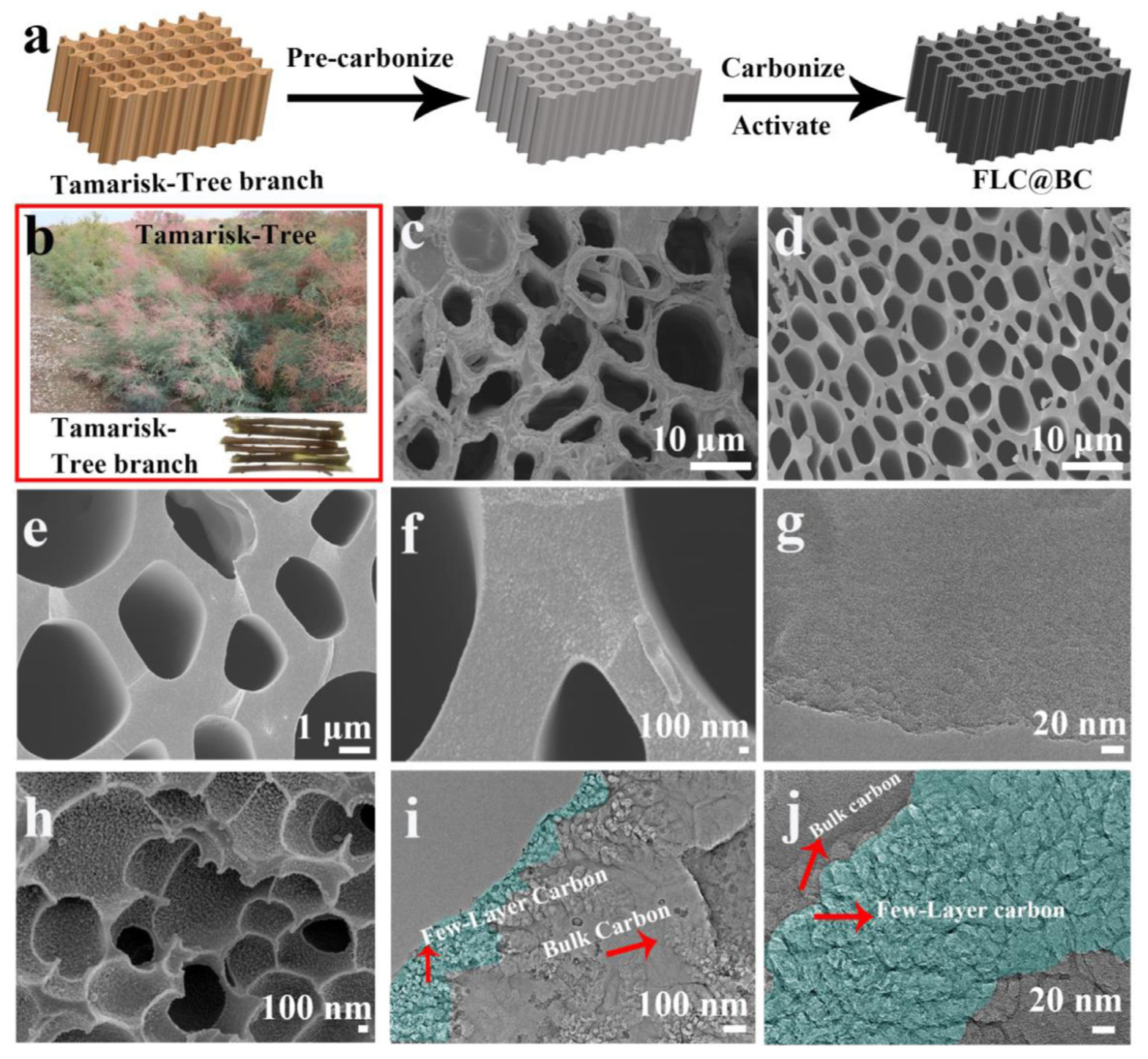
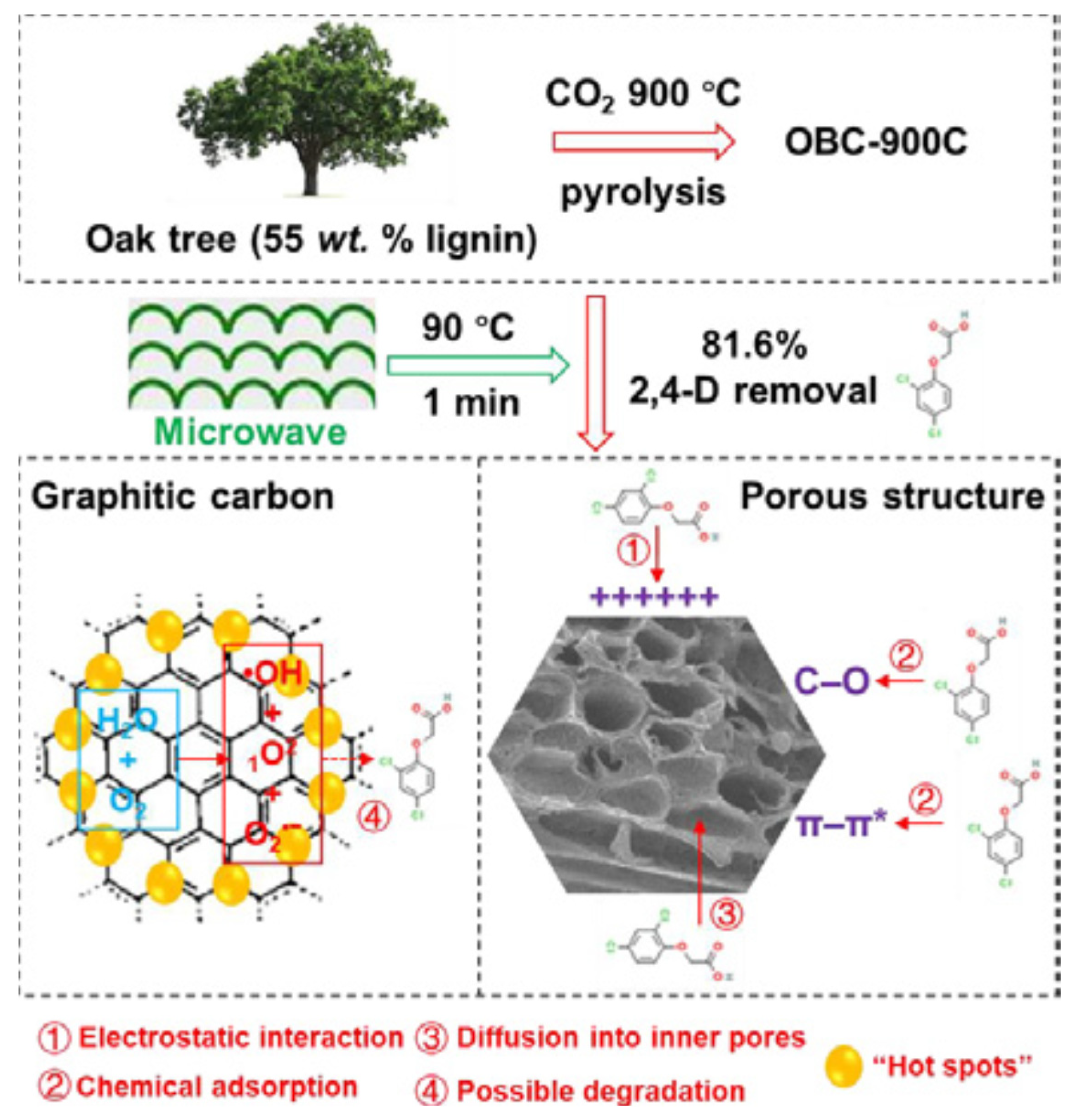
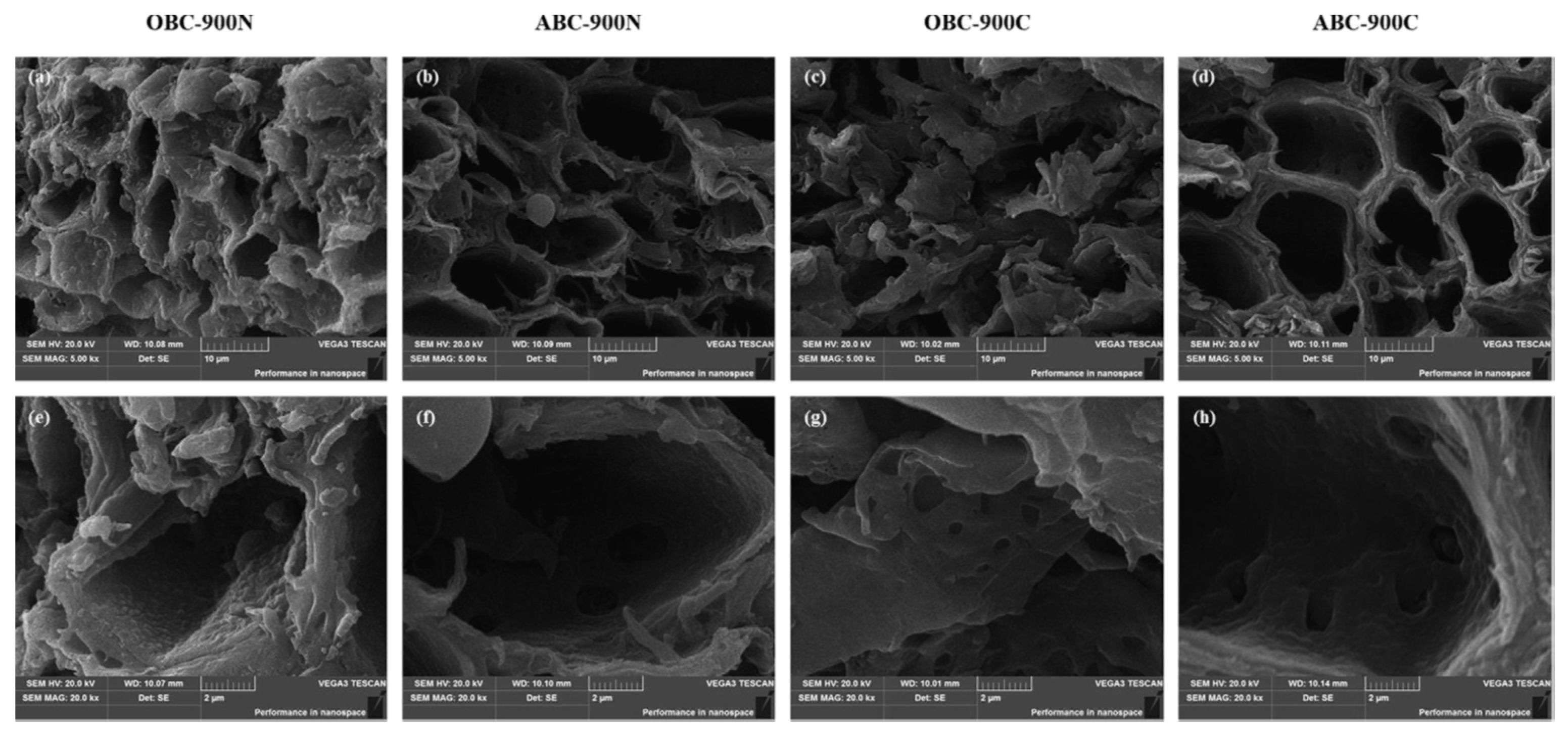
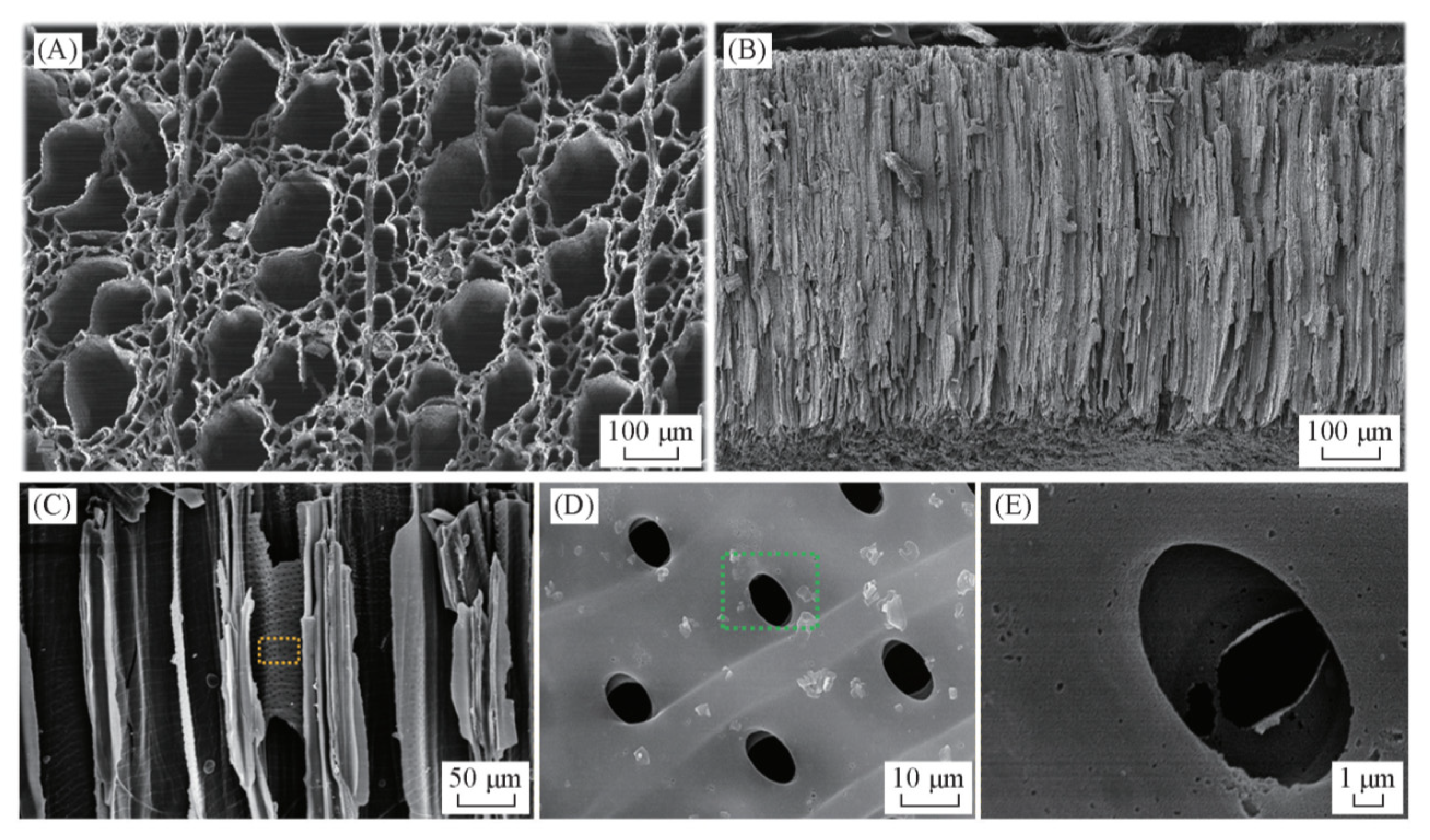
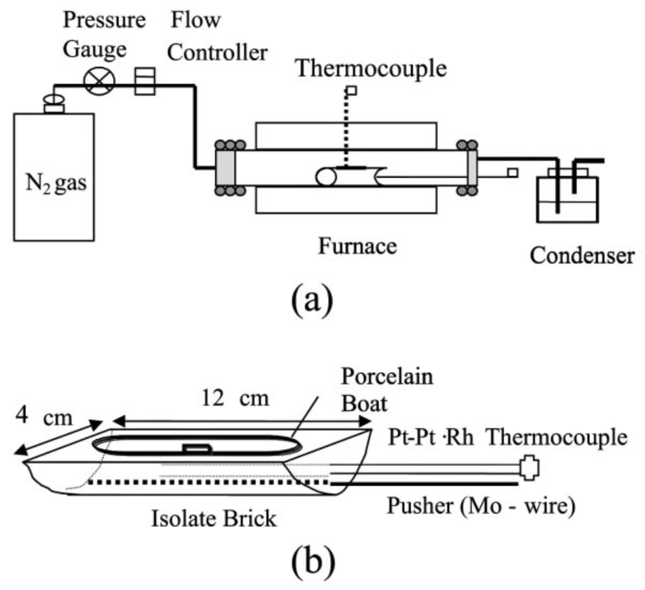
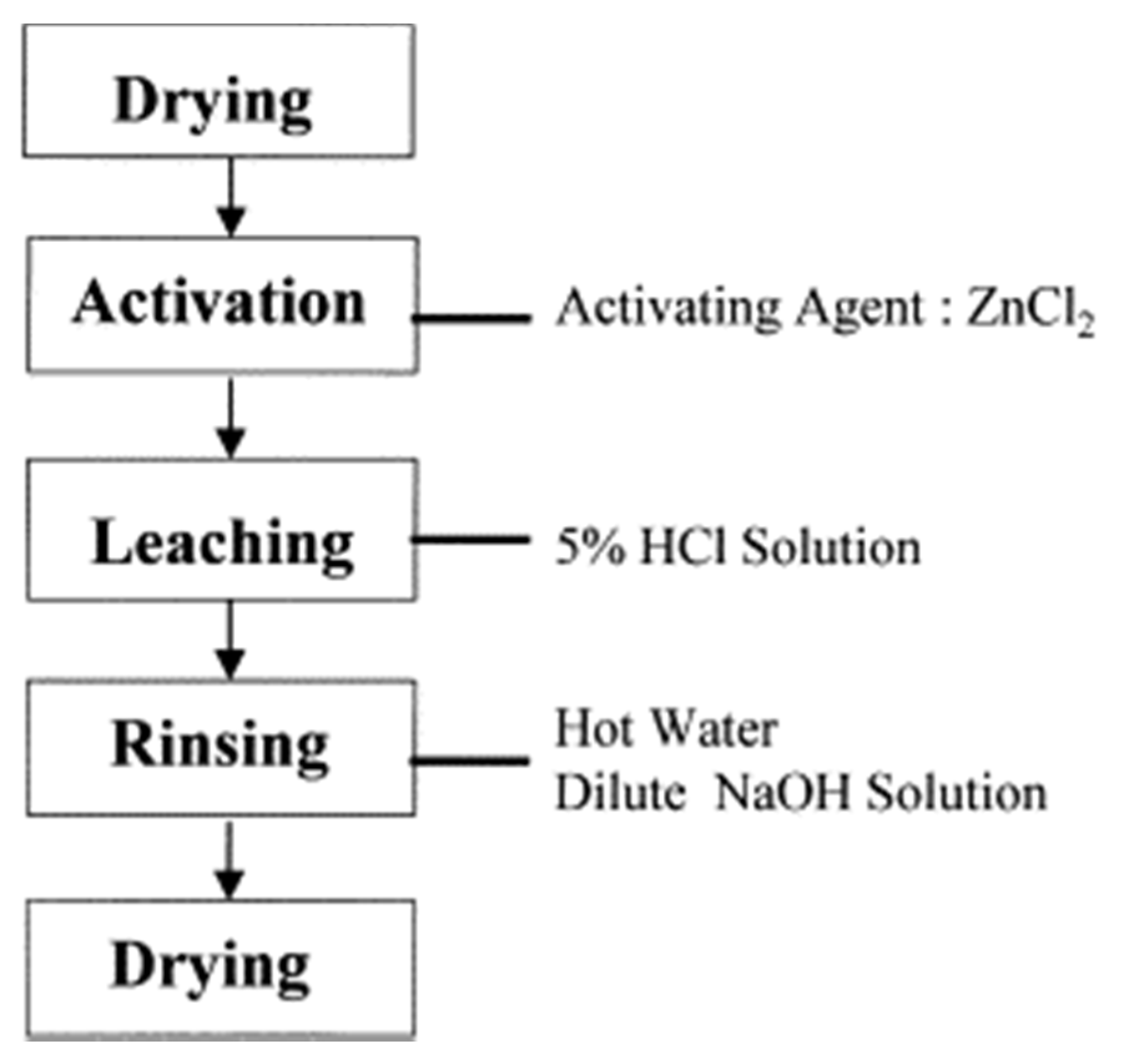
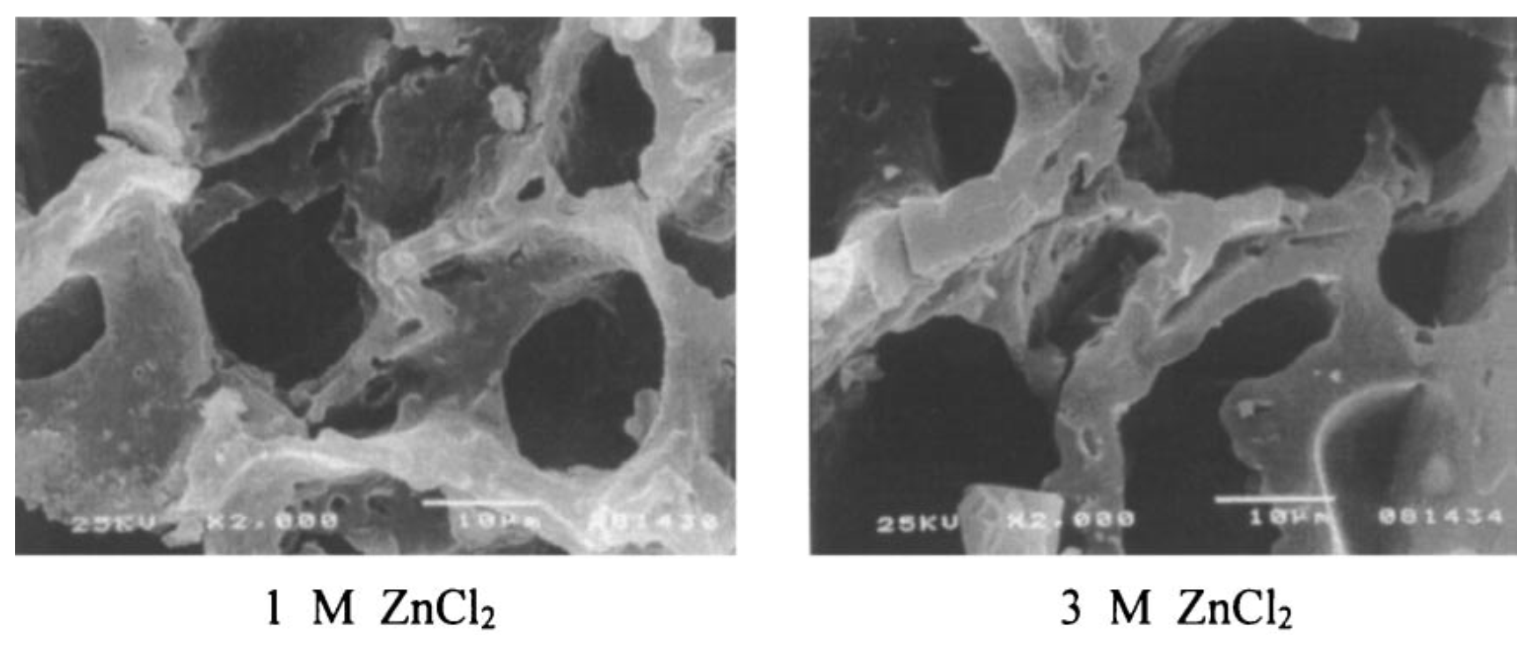
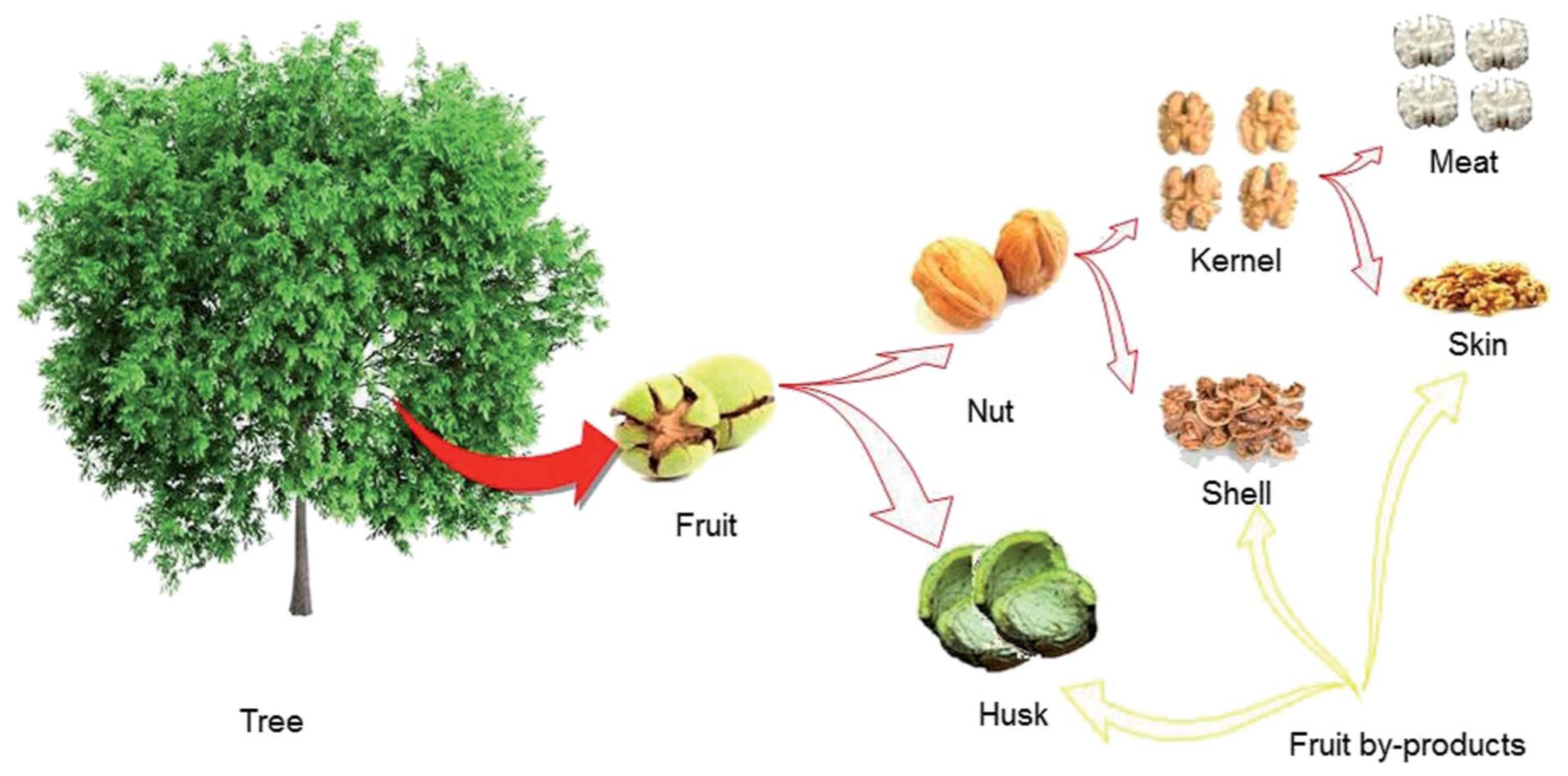
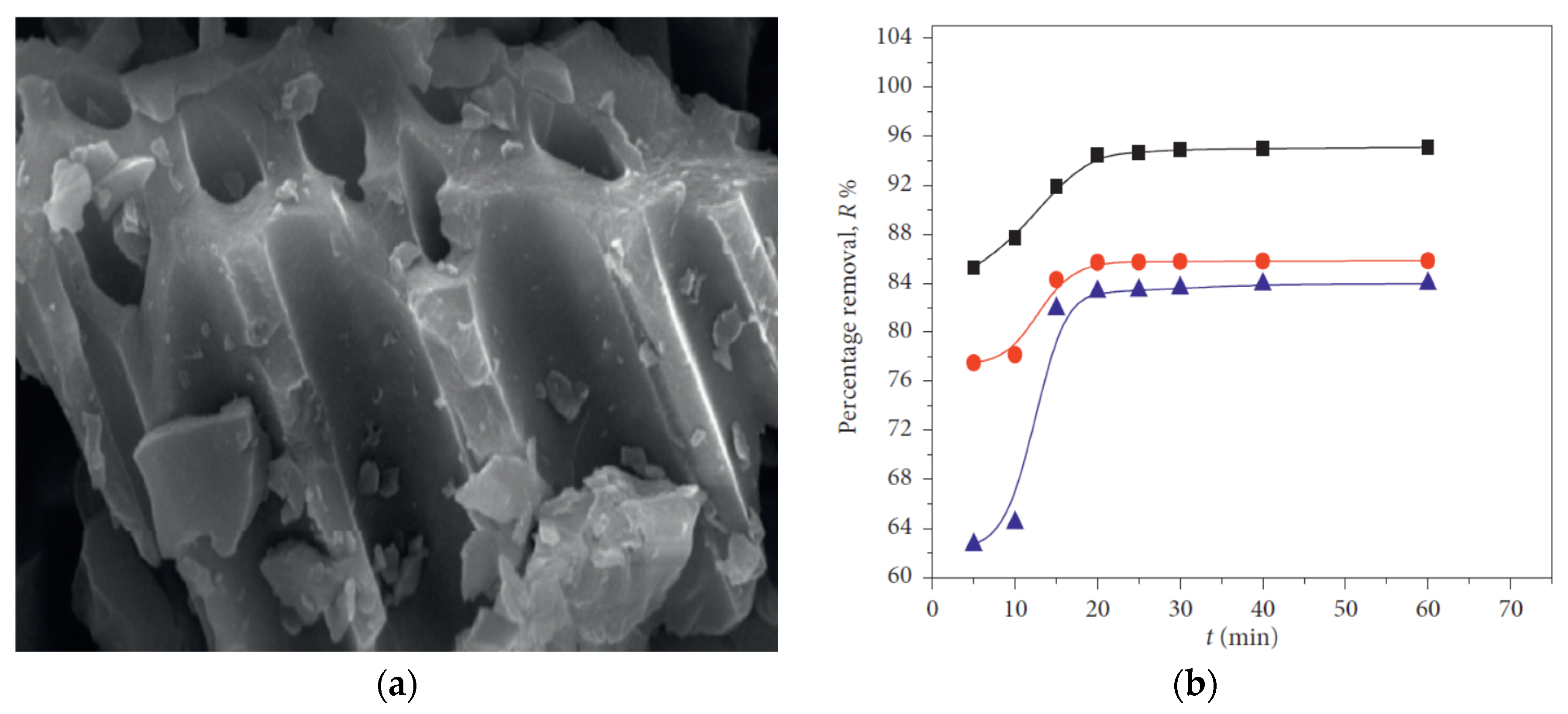
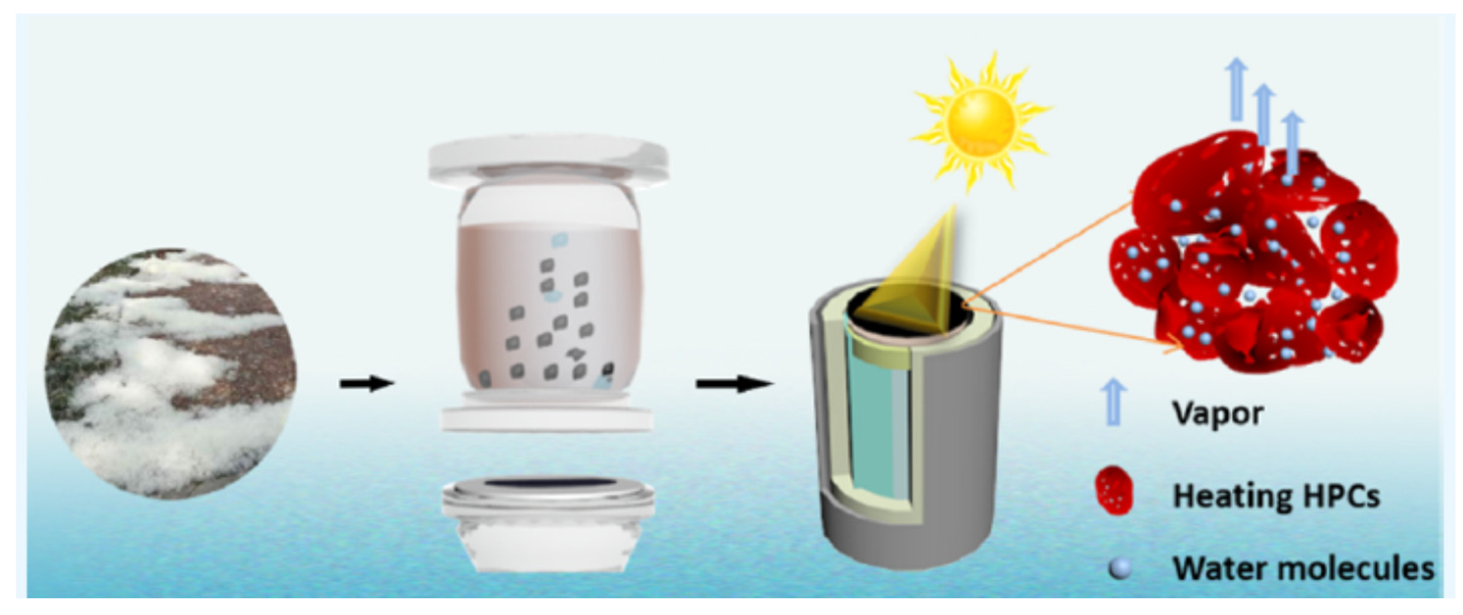
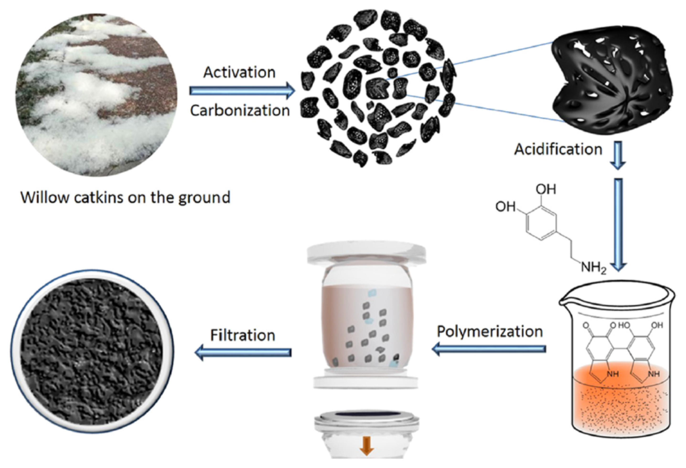
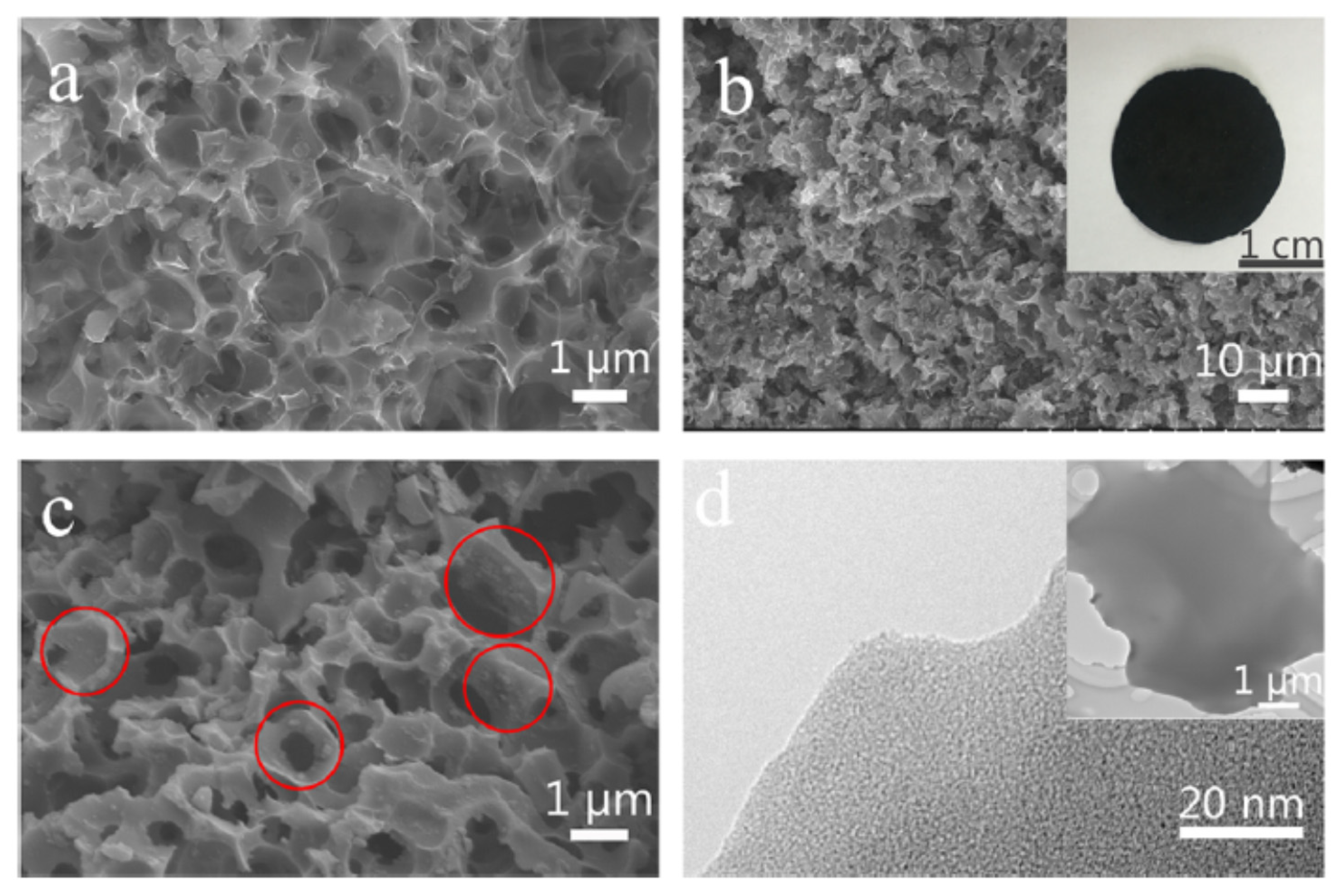
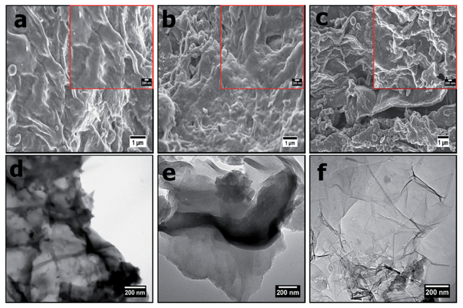
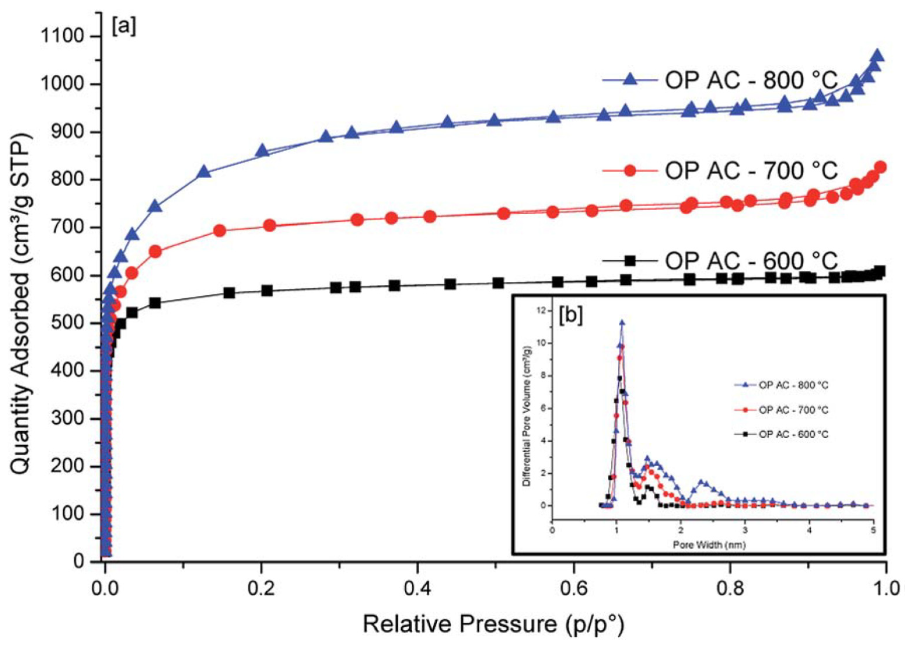
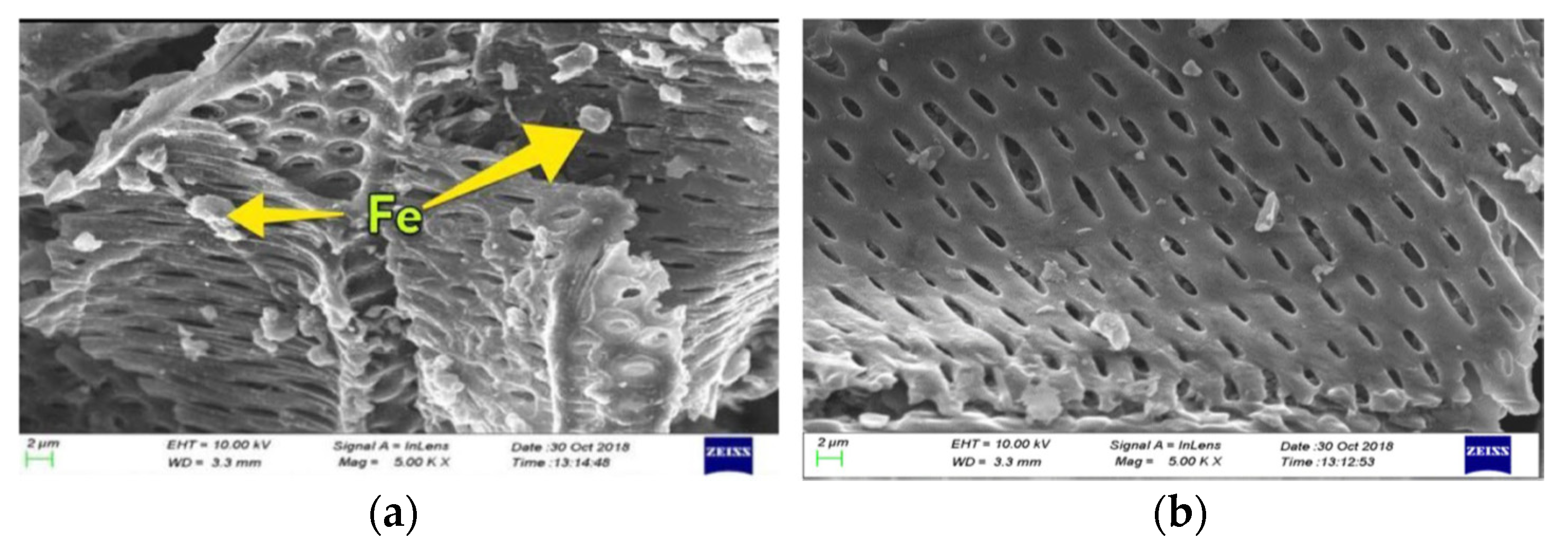
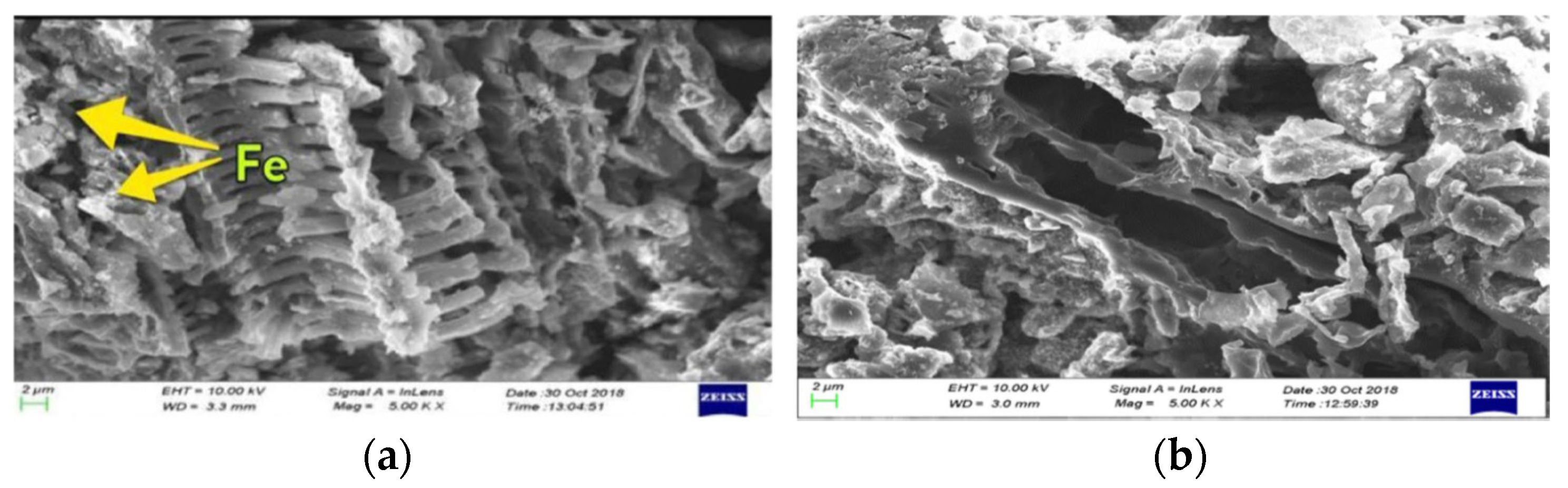
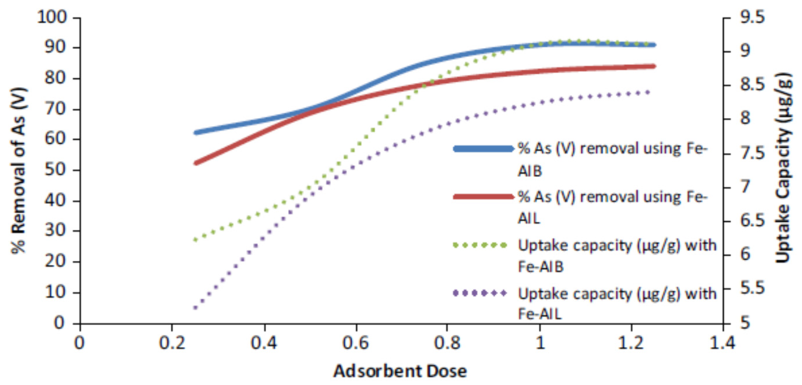
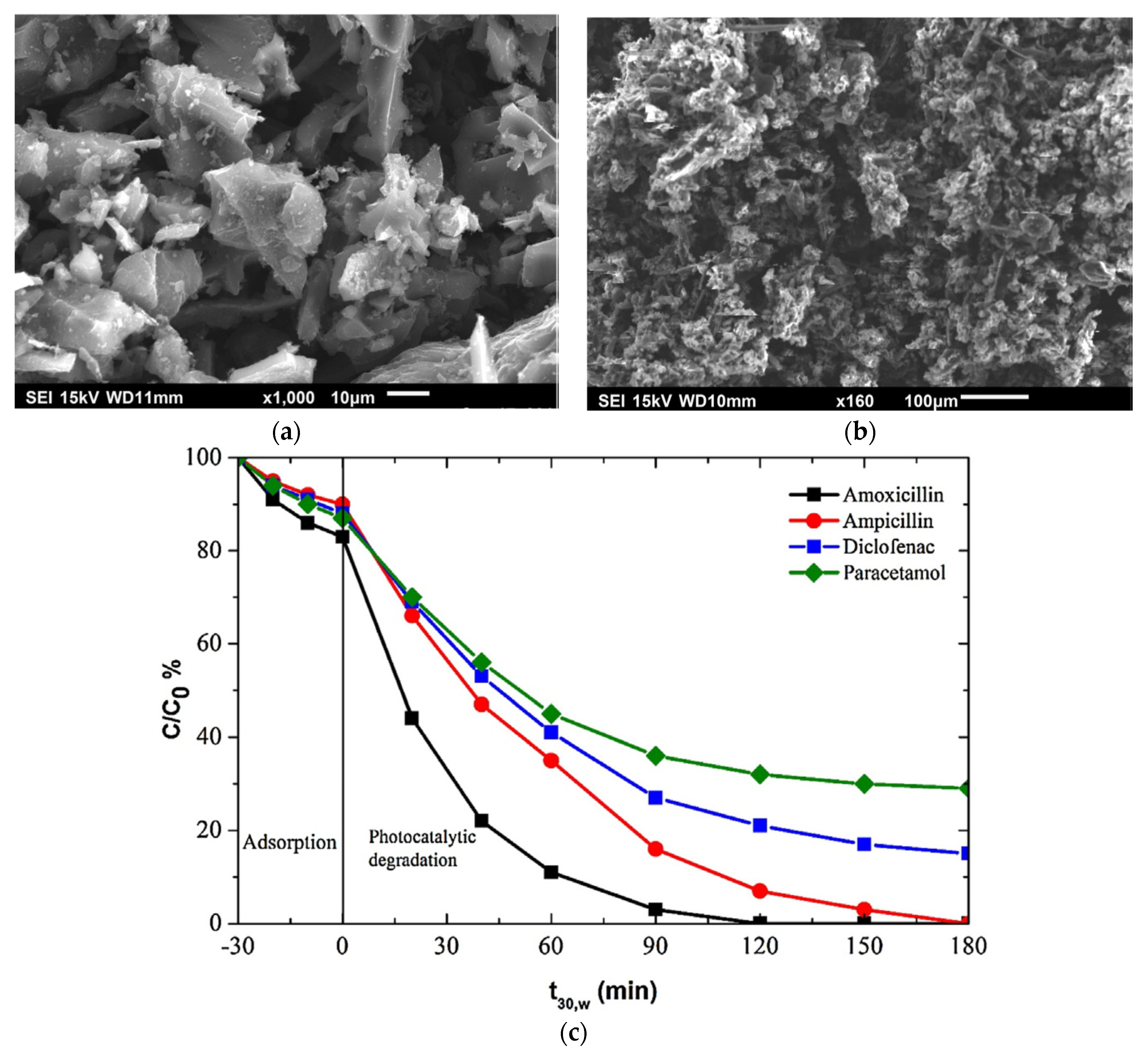
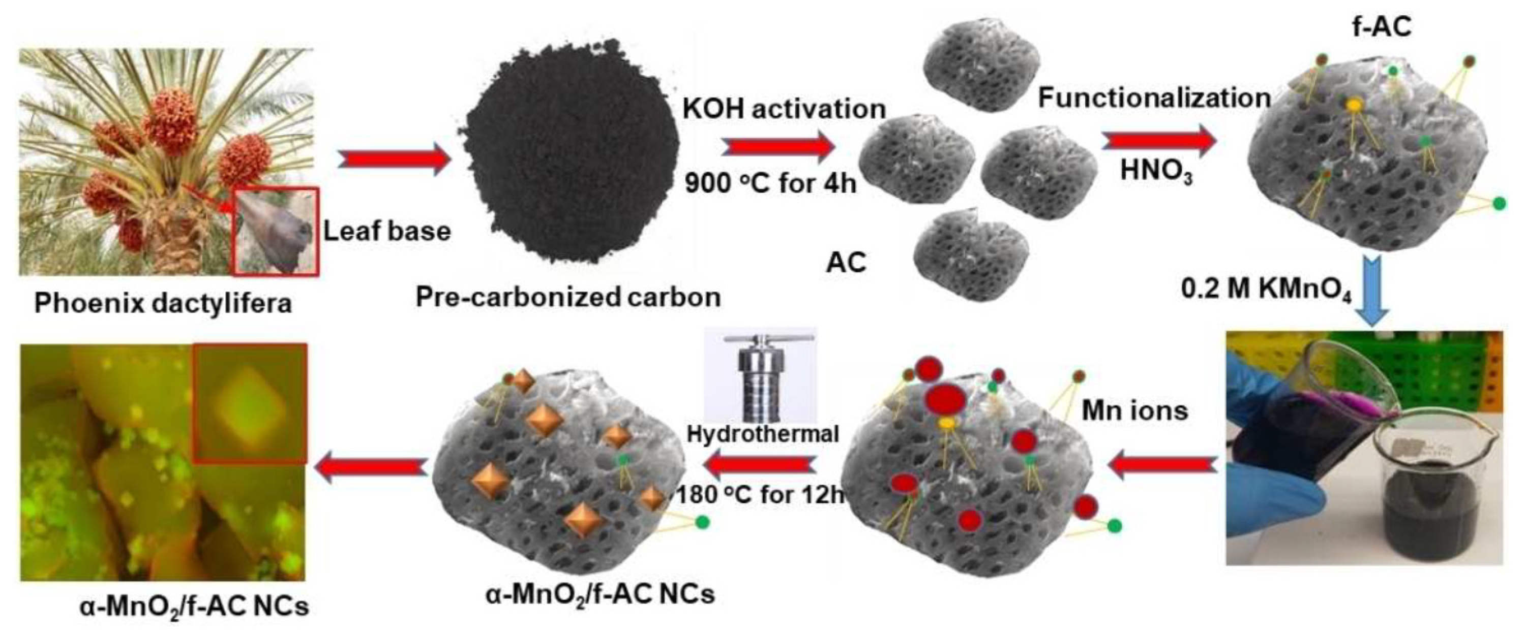
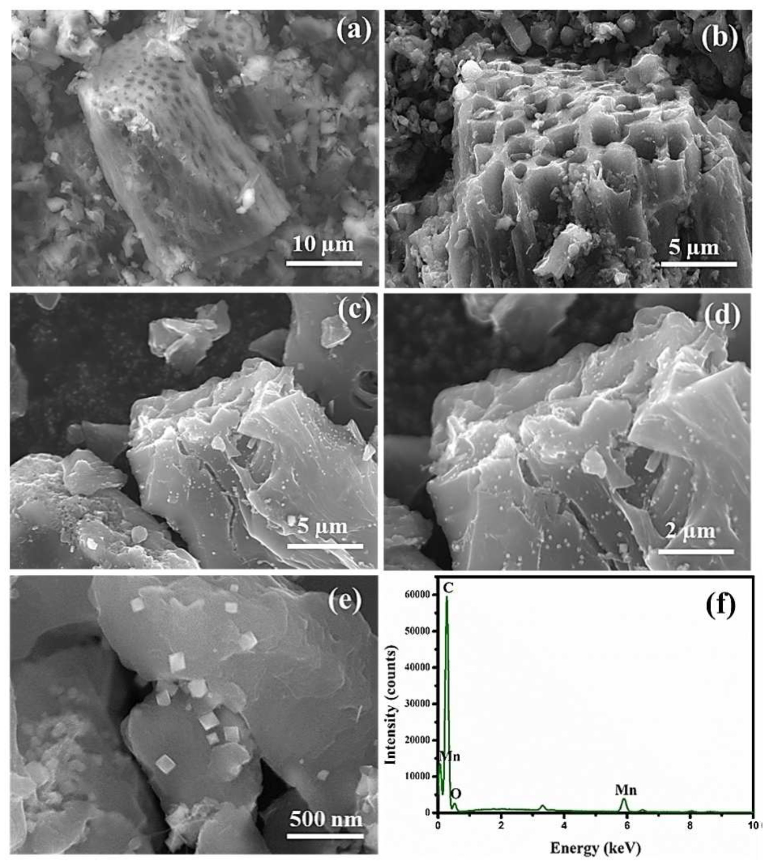
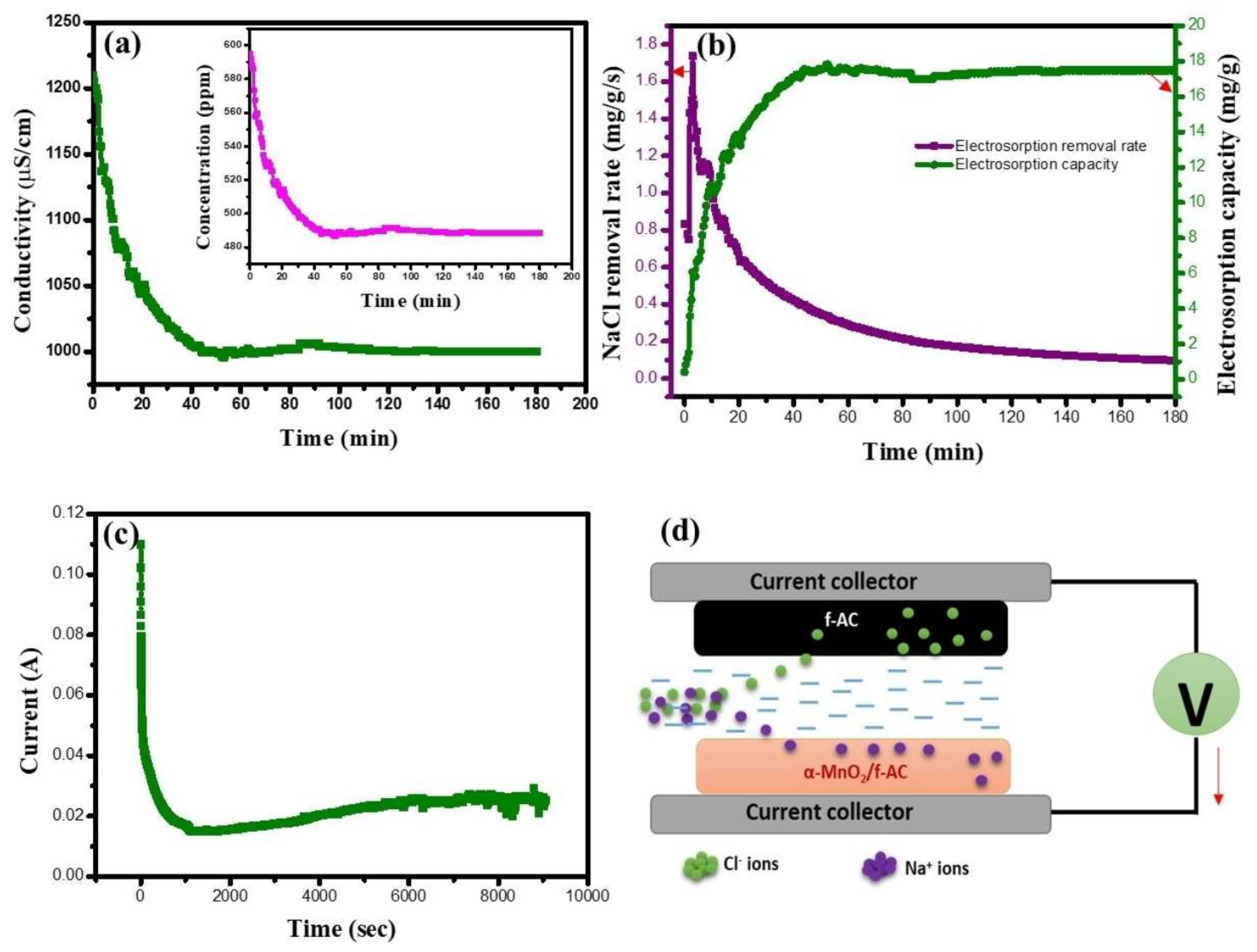
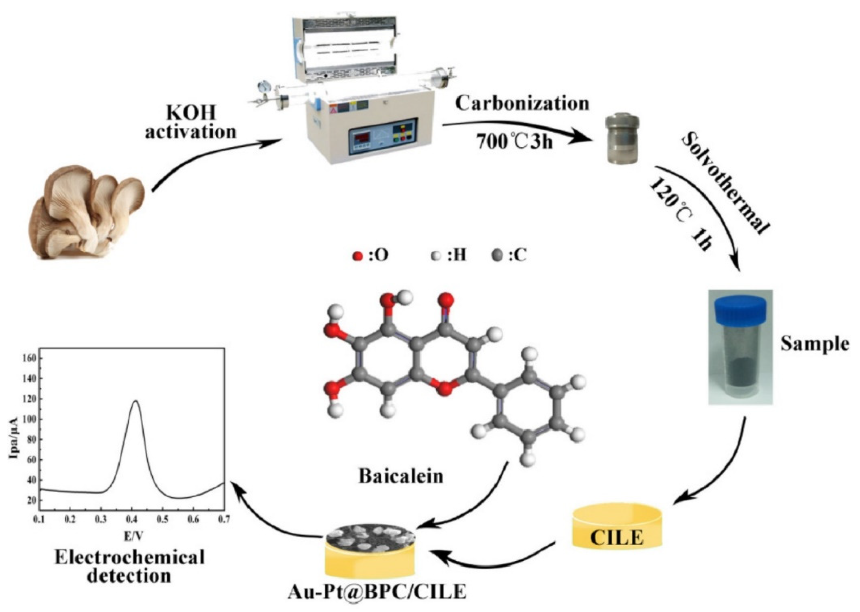
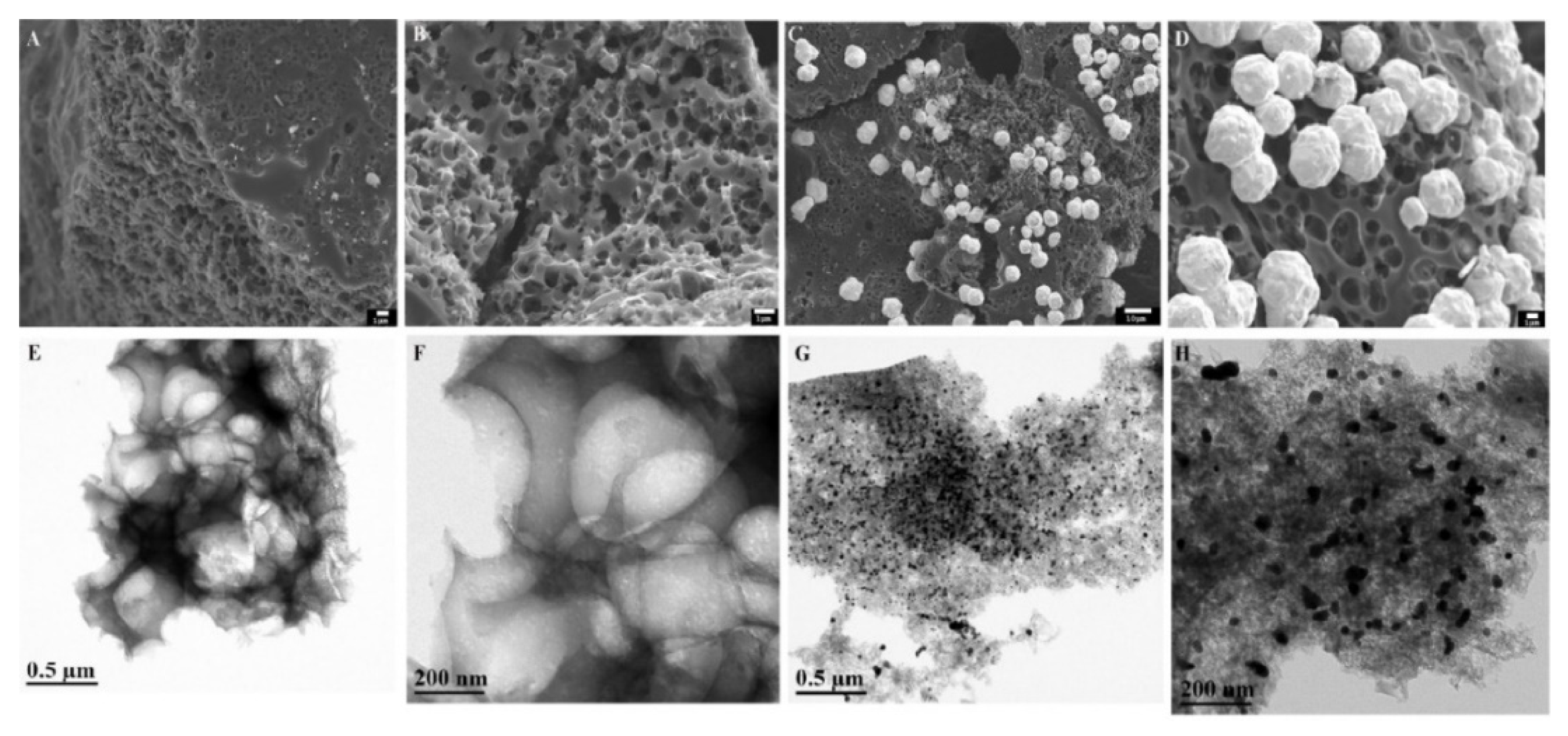
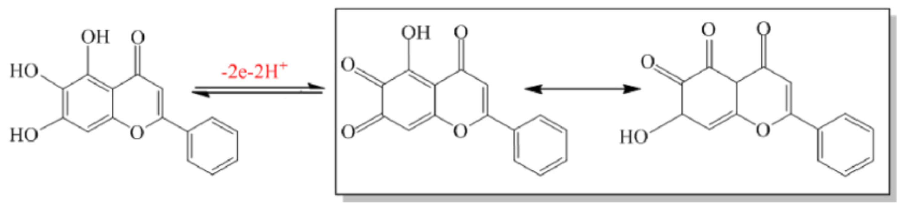
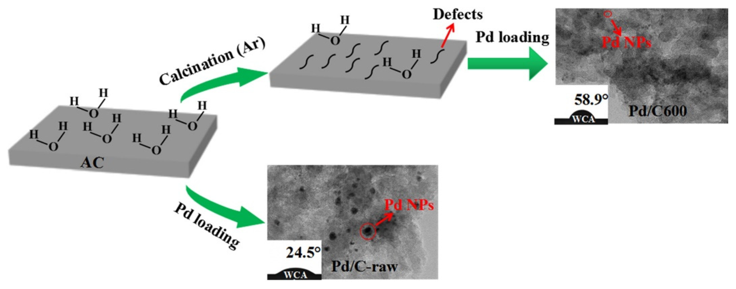
Table 1.
Textural properties of the onion peel-derived activated carbons produced at 600, 700, and 800 °C. Adopted with permission from [23], ©2020 The Authors.
Table 1.
Textural properties of the onion peel-derived activated carbons produced at 600, 700, and 800 °C. Adopted with permission from [23], ©2020 The Authors.
| Sample Name | BET Surface Area (m2/g) | Micropore Area (m2/g) | Total Pore vol. (cm3/g) | Micropore vol. (cm3/g) | H2 Uptake (wt%) |
|---|---|---|---|---|---|
| OP AC-600 °C | 2241 | 2220 | 0.94 | 0.89 | 3.08 |
| OP AC-700 °C | 2706 | 2651 | 1.28 | 1.10 | 3.29 |
| OP AC-800 °C | 3150 | 3080 | 1.64 | 1.39 | 3.67 |
Table 2.
Comparison of the specific capacitance and electrosorption capacity of different CDI electrodes. Adopted with permission from [43], ©2020 The Authors.
Table 2.
Comparison of the specific capacitance and electrosorption capacity of different CDI electrodes. Adopted with permission from [43], ©2020 The Authors.
| Electrodes and Materials | Specific Capacitance (F/g) | Applied Voltage (V) | NaCl Concentration (ppm) | Desalination Capacity (mg/g) | Source |
|---|---|---|---|---|---|
| Anode: α-MnO2/f-AC Cathode: f-AC | 388 | 1.2 | 600 | 17.8 | [43] |
| ZnO/activated carbon | 66 | 1.2 | 500 | 9.4 | [45] |
| N-doped cluster-like porous C | 199 | 1.2 | 100 | 11.98 | [46] |
| Graphene–chitosan–Mn3O4 | 190 | 1.6 | 300 | 12.7 | [47] |
| MnO2-nanorods@graphene | 292 | 1.2 | --- | 5.01 | [48] |
| Sulfonated carbon/TiO2 | 238 | 1.2 | 500 | 10.0 | [49] |
| N-doped porous C | 292 | 1.4 | 500 | 16.63 | [50] |
| rGO–SnO2 nanocomposite | 142 | 1.2 | 400 | 17.62 | [51] |
| TiO2-nanotube array with carbon embedded electrode | 238 | 1.2 | 500 | 13.11 | [52] |
| Nanoporous 3D Graphene | 200 | 1.6 | 500 | 17.1 | [53] |
| GO/ZrO210% | 452 | 1.2 | 50 | 4.76 | [54] |
Publisher’s Note: MDPI stays neutral with regard to jurisdictional claims in published maps and institutional affiliations. |
© 2021 by the author. Licensee MDPI, Basel, Switzerland. This article is an open access article distributed under the terms and conditions of the Creative Commons Attribution (CC BY) license (https://creativecommons.org/licenses/by/4.0/).
Share and Cite
MDPI and ACS Style
Gan, Y.X. Activated Carbon from Biomass Sustainable Sources. C 2021, 7, 39. https://doi.org/10.3390/c7020039
AMA Style
Gan YX. Activated Carbon from Biomass Sustainable Sources. C. 2021; 7(2):39. https://doi.org/10.3390/c7020039
Chicago/Turabian StyleGan, Yong X. 2021. "Activated Carbon from Biomass Sustainable Sources" C 7, no. 2: 39. https://doi.org/10.3390/c7020039
APA StyleGan, Y. X. (2021). Activated Carbon from Biomass Sustainable Sources. C, 7(2), 39. https://doi.org/10.3390/c7020039
Note that from the first issue of 2016, this journal uses article numbers instead of page numbers. See further details here.