Article

An Atomistic Carbide-Derived Carbon Model Generated Using ReaxFF-Based Quenched Molecular Dynamics

1
Department of Chemical and Biomolecular Engineering, Vanderbilt University, Nashville, TN 37235, USA
2
Vanderbilt Multiscale Modeling and Simulation (MuMS) Center, Vanderbilt University, Nashville, TN 37235, USA
3
Department of Materials Science and Engineering and the A.J. Drexel Nanomaterials Institute, Drexel University, Philadelphia, PA 19104, USA
4
Shull Wollan Center, The University of Tennessee/Oak National Laboratory, Oak Ridge, TN 37831, USA
5
Department of Chemical and Biological Engineering, University of Alabama, Tuscaloosa, AL 35487, USA
6
Center for Nanophase Materials Sciences, Oak National Laboratory, Oak Ridge, TN 37831, USA
7
Department of Mechanical and Nuclear Engineering, The Pennsylvania State University, University Park, PA 16802, USA
*
Author to whom correspondence should be addressed.
Submission received: 3 September 2017 / Revised: 6 October 2017 / Accepted: 10 October 2017 / Published: 23 October 2017

Abstract

:
We report a novel atomistic model of carbide-derived carbons (CDCs), which are nanoporous carbons with high specific surface areas, synthesis-dependent degrees of graphitization, and well-ordered, tunable porosities. These properties make CDCs viable substrates in several energy-relevant applications, such as gas storage media, electrochemical capacitors, and catalytic supports. These materials are heterogenous, non-ideal structures and include several important parameters that govern their performance. Therefore, a realistic model of the CDC structure is needed in order to study these systems and their nanoscale and macroscale properties with molecular simulation. We report the use of the ReaxFF reactive force field in a quenched molecular dynamics routine to generate atomistic CDC models. The pair distribution function, pore size distribution, and adsorptive properties of this model are reported and corroborated with experimental data. Simulations demonstrate that compressing the system after quenching changes the pore size distribution to better match the experimental target. Ring size distributions of this model demonstrate the prevalence of non-hexagonal carbon rings in CDCs. These effects may contrast the properties of CDCs against those of activated carbons with similar pore size distributions and explain higher energy densities of CDC-based supercapacitors.

Graphical Abstract

1. Introduction

Carbide-derived carbons (CDCs) are a class of porous carbons with well-ordered porosities and heterogeneous, short-range graphitic ordering [1]. The most common synthesis approach uses halogen gas (typically Cl2) to selectively etch out the metal phase of a metal carbide (e.g., TiC [2], Mo2C, [3] or TiAlC2 [4]) at high temperatures 200 200 C –1200 C [5]. They have high surface areas (typically 1000–2000 m 2 /g) and a tunable pore size distributions in the microporous and mesoporous regimes [2,6,7,8]. These properties, in addition to the chemical, thermal, and electrical stability of carbon, make CDCs an appealing electrode material for electrochemical energy storage [2,9,10,11,12] and substrate for gas [2,13,14,15] and protein [16,17] separation and storage.
Carbide precursor, particle size [18], and synthesis conditions influence the resulting porosities, carbon bonding and graphitic defects, and surface chemistries of CDCs [19]. Low-temperature synthesis typically yields micropores with narrow pore diameter distributions. In particular, 600 C –800 C Cl2 etching of SiC and TiC yield predominantly subnanometer pores [11]; their dimensions match the sizes of electrosorbed ions and yield exceptionally high energy densities as electrochemical capacitors [20]. Different carbide precursors and pore diameters yield slit or cylindrical pore shapes with different curvatures [6]. While most carbon ordering in CDCs is a heterogeneous mixture of short-ranged sp 2 and sp 3 bonding, graphitization (and resulting electron transport properties) directly depends on synthesis temperature [21]. Thermal treatment above 1000 C typically increases the prevalence of graphitic features, such as ribbons, barrels, and nanotubes [7]. These features define concentrations of structural defects (vacancies, Stone–Wales transformations, etc. [22]), pore topography and geometrical roughness [23], and degree of long-range ordering in the [100] and [002] (sheet stacking) directions [24]. In turn, these properties govern the contribution and relative influence of quantum capacitance on total charge storage densities of these materials as electrodes [25]. Finally, post-Cl2 treatment methods (H2 or NH3 600 C annealing) and exposure to air introduces various functional groups on pore surfaces [26]. These moieties also influence electrosorption dynamics [27] and capacitance [28,29]. Many of these properties are convoluted and difficult to quantify in experimental systems. Therefore, subsequent optimization of these materials requires a detailed computational model.
Even though nanoporous carbons have non-uniform structure, they are often modeled as slit pores directly in contact with a bulk fluid or electrolyte. Additional models also consider cylindrical, spherical, and other morphologies [30,31,32,33]. Nonetheless, the slit pore model remains common for the study of porous systems, even for studying advanced properties such as gas adsorption [34,35] and separation [36], capacitance [23], and the structure and dynamics of confined ions [37,38] and molecules [39]. In such model systems, parallel sheets of graphene are separated by the characteristic widths of the nanopores found in experiment, typically defined as the peak in the pore size distribution. These models capture, to a first approximation, the effect of confinement on fluid behavior, but leave out many other effects. CDCs and other nanoporous materials have structural heterogeneities such as surface curvature and a distribution of pore widths, which have qualitative and quantitative effects on the performance of CDCs as electrodes in supercapacitors [40,41] or as adsorbents of gas molecules [42]. Furthermore, direct exposure of a nanopore to a bulk fluid ignores entrance effects and dynamics associated with transport through a complex pore architecture [43]. Therefore, to better understand the fundamentals of gas sorption, electric double layer structure, and electrolyte dynamics in CDCs, a structurally valid model for CDCs that captures these effects is needed.
Reverse Monte Carlo (RMC) [44,45] is one approach that has been used to create structurally relevant nanoporous models [46,47,48,49]. These models are created in an iterative process of fitting simulated radial distribution functions (RDFs) to those obtained from scattering experiments. While CDC structures have been generated that reproduce experimental RDFs, fits of empirical information to an RDF with an RMC routine have inherent limitations. Structural features on the order of a few nanometers, particularly porosity and surface curvature, are not typically well-captured with RDFs, which usually decay to unity in a few angstroms. Additionally, while RMC is capable of producing robust fits to experimental data, many unique three-dimensional models may be generated from a single, one-dimensional RDF. Subsequently, results derived using RMC cannot formally be considered unique [50,51,52]. Furthermore, as with many Monte Carlo-based methods, accessible system size may be limited due to the challenges of deploying algorithms to parallel computing architectures. Small systems on the order of a few hundred or thousand atoms are sufficient for capturing short-range features such as bonding, ring formations, and a small number of structural features and pores. Larger system sizes on the order of tens or hundreds of thousands of atoms are needed to better sample a range of structural heterogeneities and pore size distributions.
As an alternative approach, quenched molecular dynamics (QMD) has viably reproduced atomistic models of amorphous and/or porous carbons [53,54,55], silica [56,57,58], and metals [59,60]. QMD generates metastable structures by lowering the temperature of a system over the course of a simulation. Although this process lacks a direct physical analog (i.e., in practice, CDCs are typically formed via chemical etching), QMD is, nonetheless, capable of generating realistic atomistic models of porous materials. This technique allows quench rate and initial and final temperatures to be modulated in order to control some of the structural properties of the CDC, such as porosities and RDFs. The inherent parallel nature of molecular dynamics simulations allows them to explore large system sizes. Previous QMD results have used force fields such as the Adaptive Intermolecular Reactive Empirical Bond Order (AIREBO) [61], the Environment-Dependent Interatomic Potential (EDIP) [62], the Reactive Summation State (RSS) [53], and the Tersoff potential [63] to generate nanoporous carbon structures for use in molecular simulation. While many impactful studies [49,52,54,55,64,65,66] have been done with these forcefields, the generated structures have often failed to accurately reproduce experimental pore size distributions and always depend, at least in part, on the accuracy of the force field itself. Carbon-based materials, and CDCs in particular, present a unique challenge for these forcefields because of their nanoscale heterogeneity. Individual forcefields can sufficiently describe specific structural moeities, such as short-range graphitization at low density [67], but are often not sufficient to capture the full range of non-ideal features observed in CDCs [68].
One possible way to increase the accuracy of computationally derived CDC structures is to employ sophisticated reactive forcefields, such as ReaxFF [69,70]. ReaxFF uniquely includes three- and four-body, non-bonded van der Waals, and electrostatic interactions in conjunction with a long-range bond order concept, where parameter sets are trained to reproduce a range of first-principles data describing reaction energies as well as reaction barriers. This allows ReaxFF to largely approach the accuracy of first-principles calculations, but at significantly (several orders of magnitude) reduced computational cost, although, we note more costly than other reactive and non-reactive force fields [52]. The use of ReaxFF for the formation of CDC structures is limited, with only a single recent study [71] examining the formation of amorphous carbon structures using QMD. This study examined the carbon hybridization, ring formation, and pore size distribution as a function of density and quench rate, and demonstrated the potential that ReaxFF could be effective in generating model CDCs; however, the study was not explicitly focused on the formation of experimentally relevant CDCs. EDIP, which has been shown to exhibit similar behavior to ReaxFF at low density [67], has been used to generate CDCs via removal of metal atoms from a carbide lattice and subsequent annealing at the target density, showing close agreement with experimental pore size distributions.
Here, we further explore the use of the ReaxFF force field to develop novel, structurally relevant atomistic models of CDCs. Our combined computational and experimental approach directly compares experimentally-derived structural information to properties of models derived from simulation. Here, we examine the effects of quench rate on CDC structure, including a slower rate than was used in prior ReaxFF studies [71]. We also investigate the role of a novel post-quenching compression step as a means to adjust pore size distribution. CDC structure is examined, including pore size distributions, pair distribution functions, and ring sizes. These analyses make comparisons to X-ray scattering, nitrogen sorption, and electron microscopy results. We demonstrate close agreement between experiment and simulation, including pore size distributions, for our approach.

2. Computational Details

2.1. Quenched Molecular Dynamics Simulations

Reactive molecular dynamics simulations were performed using the ReaxFF [69,72,73] force field implemented in the LAMMPS [74] simulation package (Version 27-Jul-2013, Sandia National Laboratory, Albuquerque, NM, USA). ReaxFF is a reactive potential that models the breaking and formation of chemical bonds through bond order, which is calculated from interatomic distances and used in calculating a bond energy. Three- and four-body, non-bonded van der Waals, and electrostatic interactions are also included. Parameter sets are developed by fitting to structural and thermodynamic properties to quantum density functional theory (DFT) data. The specific ReaxFF parameter set used in this study was optimized for modeling carbon materials [70].
Initial configurations were generated by assigning 20,000 carbon atoms to random positions in a periodic simulation cell of length 7.488 nm. This corresponded to a bulk density near 0.95 g/cm 3 , consistent with previous studies [49,55]. In an attempt to mitigate biases arising from an ordered initial state, random positions give the system a fluid-like initial state. Quenched molecular dynamics simulations were performed from an initial temperature of 3500 K to a final temperature of 3000 K . The use of temperature ranges higher than used in experiment is a common approach in ReaxFF studies to bring reaction kinetics into a time scale accessible in molecular simulation [70,75,76]. This temperature range is near the phase transition from liquid carbon to graphite at low pressures reported by experiment [77,78]. While the melting point was not rigorously examined with this force field, the transition appears to occur within the range expected from experiment. In simulations of the lengths considered here, major structural changes do not occur after the system has condensed from a fluid to solid state, so additional quenching below 3000 K was not considered. In order to explore the effects of quench rate, simulations varied from 5 ps to 500 ps in length, giving quench rates between 1 and 100 k/ps. These rates are studied for their effects on the structures and are not to be interpreted physically or compared directly to synthesis parameters. Temperature was controlled using a Nosé–Hoover thermostat with a damping constant of 10 f s . All quenching simulations were performed in the canonical (NVT) ensemble and a 0.5 f s time step was used throughout. This is a larger timestep than what is normally used in ReaxFF studies (0.25 f s ); however, these systems include only carbon atoms and therefore lack any O-H or C-H vibrations, which are much faster than C-C vibrations.
For select samples, an additional compression step was applied after the quenching step using the NPT ensemble. The NPT integrator follows the work of Shinoda et al. [79], combining the work of Martyna et al. [80] and Parrinello and Rahman [81], as implemented in LAMMPS. The ReaxFF force field was again applied with a time step of 0.5 f s . Isothermal temperature control and isobaric pressure control at 3000 K and 20,000 atm were used with damping constants of 10 f s and 100 f s , respectively. Selection of this pressure is discussed in the Supplementary Material, including the relationship between system density and compression pressure in Figure S1. Like the quenching step, there is no direct physical analog to this step, but it was used to drive structural properties toward the experimental target. Effects of the post-quenching compression step are discussed in context below. For both compressed and non-compressed samples, no additional structural relaxation was performed.

2.2. Grand Canonical Monte Carlo Simulations

In order to study the properties of QMD-generated CDC models as adsorbent materials, grand canonical Monte Carlo (GCMC) simulations of nitrogen isotherms were performed with LAMMPS. A single-site nitrogen model was utilized as the fluid and both fluid–fluid and fluid–solid interactions were described with 12–6 Lennard–Jones potentials. A cut-off distance of 15   Å was used with no long-range corrections. Carbon and nitrogen atoms were described using ϵ C = 28.0   K , ϵ N = 95.2   K , σ C = 3.4   Å , and σ N = 3.75   Å . Lorentz–Berthelot mixing rules were used, giving ϵ C / N = 51.6   K and σ C / N = 3.575   Å . The carbon substrate was fixed in position; only moves involving nitrogen sites were considered. Construction of simulated isotherms for each carbon structure involved many short simulations of 2 × 10 6 translation attempts and 2 × 10 6 insertion/deletion attempts. At a fixed temperature of 77 K , a range of 40 pressures ranging from 1 × 10⁻⁶ atm to 1 atm for the bulk fluid were considered. Beginning with a bare carbon structure at the minimum pressure of 1 × 10⁻⁶ atm , the aforementioned short simulations were repeated at the same pressure until changes in the number of nitrogen atoms in the system were sufficiently close to zero to be considered at equilibrium. Subsequent pressure values incremented by a small amount and this process repeated until all pressures in the prescribed range were considered.

3. Experimental Methods

3.1. CDC Synthesis and Annealing

Porous CDC particles were synthesized using a previously described procedure [5]. Silicon carbide (SiC) particles (1.0 μ m –5.0 μ m diameter, 99.1+ % purity, Alfa Aesar, Haverhill, MA, USA) were placed into a quartz boat and loaded into a tube furnace. The furnace ramped up to 900 C under flowing Ar gas. Once the system reached this temperature, pure Cl2 gas flowed over the furnace at a rate of 0.5 L min 1 for 4 h and etched away the metal carbide using the following reaction [82]:
2Cl2(g) + SiC(s) → SiCl4(g) + C(s).
Subsequently, the system cooled down to 600 C and H2 gas annealed the leftover carbon particles for 2 h [26]. Finally, the material cooled down to room temperature under flowing Ar.
The material was placed into a graphite crucible and loaded into a vacuum furnace (Solar Atmospheres, Souderton, PA, USA). The furnace outgassed for 24 h until a high vacuum (1 × 10⁻⁶ torr ) was reached [7]. Under continuously pulled vacuum, the furnace ramped up at a 10 C min 1 rate up to 700 C , held at that isothermal condition for 11 h, and, subsequently, cooled to room temperature [83]. This step removed all non-carbon functional groups, impurities, and moieties (adsorbed from air exposure or byproducts of CDC synthesis) from the CDC surface.

3.2. Gas Sorption and Porosimetry

Gas sorption measurements were carried out using Quadrasorb sorption analyzer (Quantachrome Instruments, Boynton Beach, FL, USA). Samples (0.050 g –0.075 g ) were loaded into glass cells and outgassed at 120 C for 24 h prior to analysis. The instrument collected gas adsorption and desorption isotherms (adsorbed volume vs. relative pressure) using N2 adsorbate gas in the 0.00075 P P 0 –0.9995 P P 0 range ( P 0 = 760 torr). Measurements were collected at a 77 K isothermal condition using a liquid N2 coolant bath. The Brunauer–Emmett–Teller equation (BET) was used to calculate the BET specific surface area (SSA) of the CDCs [84]. The equation was calculated using a linear regression for 0.05–0.30 P P 0 values and normalized by the sample mass to obtain m 2 g 1 values.
Quenched Solid Density Functional Theory (QSDFT) data reduction analysis provided information on a secondary (DFT-derived) SSA value, cumulative pore volume cm 3 g 1 values), and pore size distributions (PSDs, pore diameter vs. d V d r plots) [30]. The data reduction used only the adsorption isotherms and assumed slit pore configurations [85]. Quantachrome’s Quadrawin software (Version 5, Quantachrome Instruments, Boynton Beach, FL, USA) provided all BET calculations and DFT data modeling kernels and computational analysis.

3.3. Ex Situ X-Ray Total Scattering

Synchrotron X-ray total scattering data were collected at the 11-ID-B beamline at the Advanced Photon Source (APS) at Argonne National Laboratory (Lemont, IL, USA). Ground powder samples were loaded into polyimide capillaries (1 m m inner diameter) and measured in transmission mode at ambient conditions (photon energy 58.65 ke V , 0.2114 Å) using an amorphous silicon image plate detector (Perkin Elmer, Fremont, CA, USA). Scattering data of a CDCs annealed at 700 C were collected for a total of 15 min and parasitic scattering from an empty polyimide container (duplicating the assembly without a sample) and an Ni powder standard (99.99%, Sigma Aldrich, Saint Louis, MO, USA) were collected using the same setup. The program Fit2D [86] was used to calibrate the sample to detector distance and detector alignment with data from a CeO2 powder standard. Raw scattering data was integrated into Q-space spectra, applying a mask and polarization correction during integration. The normalized total scattering patterns, S ( Q ) were produced in PDFgetX2[87] (Version 1.0, Michigan State University, East Lansing, MI, USA) by subtracting polyimide container scattering, utilizing the appropriate sample composition, and applying standard corrections for the area detector setup [88]. Pair distribution function patterns, PDF G(r), were calculated via Fourier transformation of the total scattering data utilizing a Q range of 1.0 Å 1 ( Q m i n ) to 26.0 Å 1 ( Q m a x ) for the Ni dataset, and was fit in PDFgui [89] in the range 1 Å–50 Å to calibrate the instrument Q d a m p = 0.038(1) and Q b r o a d = 0.021(1) effects on real-space data. The same Q range was used for sample data. Because the diffractometer is only capable of capturing a small portion of such pore signals with the limitation of Q m i n near 0.5 Å 1 , a Fourier transform with Q m i n of 0.5 Å 1 will thus result in a weak oscillating signal with a wavelength of approximately 13 Å in the real-space domain from the 2 π Q inverse relationship. For the purpose of comparing PDFs to QMD-generated models without complications arising from incomplete measurements of pore structures, a Q m i n value of 1.0 Å was selected.

3.4. Abberation Corrected Scanning Transmission Electron Microscopy

The structure of the CDC was characterized using an abberation corrected Nion UltraSTEM (Nion Company, Kirkland, WA, USA) operating at 60 k V . Scanning transmission electron microscopy (STEM) imaging provides [90,91] atomic resolution characterization of the overall CDC morphology following the chlorine heat treatment and subsequent vacuum annealing.

4. Results and Discussion

A quenched molecular dynamics routine was used to generate atomistic models for CDCs. Images provide qualitative analyses of sample morphology and structural properties, while quantitative characterization includes pair distribution functions, pore size distributions, ring size distributions, and ring neighbor correlations. Comparisons of QMD-generated CDC models to experimental results are made in appropriate corresponding discussions.
A summary of the models is listed in Table 1. Throughout, models generated through simulation named ‘QMD-x’ where ‘x’ is the quench rate used to produce it (in units of 1 K p s 1 −100 K p s 1 ). A ‘c’ is appended to the name if a post-quench compression step was included. The experimental sample is referred to as ‘Expt.’.

4.1. Imaging and Spectroscopy of CDC Structures

Before evaluating QMD-generated CDC structures, we first consider imaging of these structures from experiments. Figure 1 shows representative annular dark-field (ADF) STEM images of the CDC structure. They reveal that the CDC structure is composed primarily of high curvature graphene sheets. The STEM images also show regions where the graphene sheets come together along their edges to form slit-like geometrical configuration. Moreover, due to the atomic-scale chemical sensitivity of ADF STEM imaging, single atoms with an atomic number greater than carbon are clearly visible in the CDC. Shown in Figure S2, Electron Energy Loss Spectroscopy (EELS) measurements from these brighter atoms confirm that these are silicon atoms, likely the result of incomplete chlorine treatment. Raman spectra were also collected on the experimental CDC sample and presented in Figure S3. Prominent D and G bands, characteristic of disordered carbon, are observed.

4.2. QMD-Generated CDC Structures

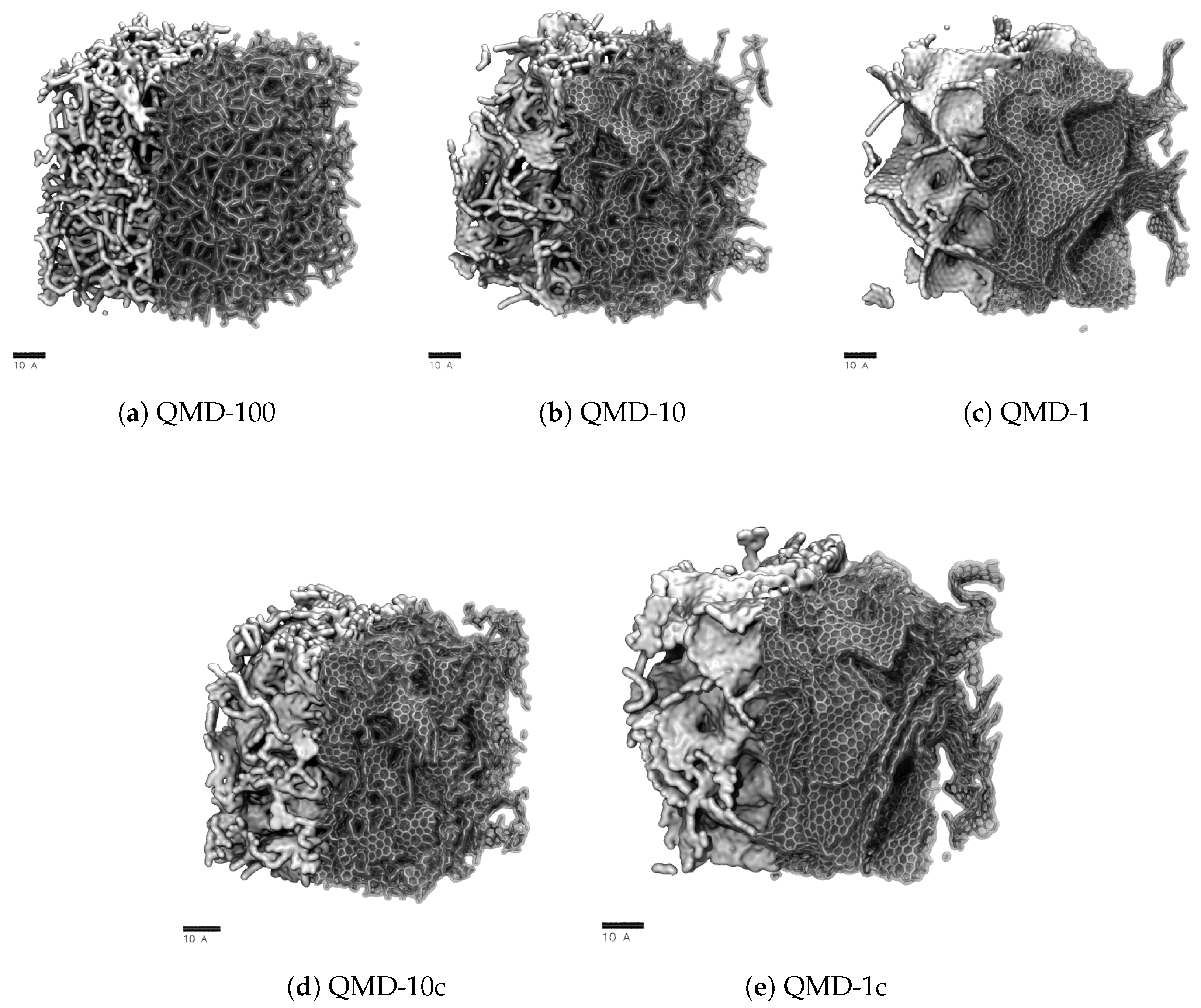
Snapshots of final-state structures produced with QMD are shown in Figure 2 and can be compared to representative STEM images of experimental samples shown in Figure 1. Simulation boxes are cubic with characteristic lengths near 7 n m . Therefore, while mesoscale features cannot be analyzed, properties on the order of few Å can be considered. In particular, we focus on the aggregation of hexagonal and non-hexagonal rings into sheet-like networks and the size distribution of pores. These properties are quantified in Figure 3, Figure 4 and Figure 5.
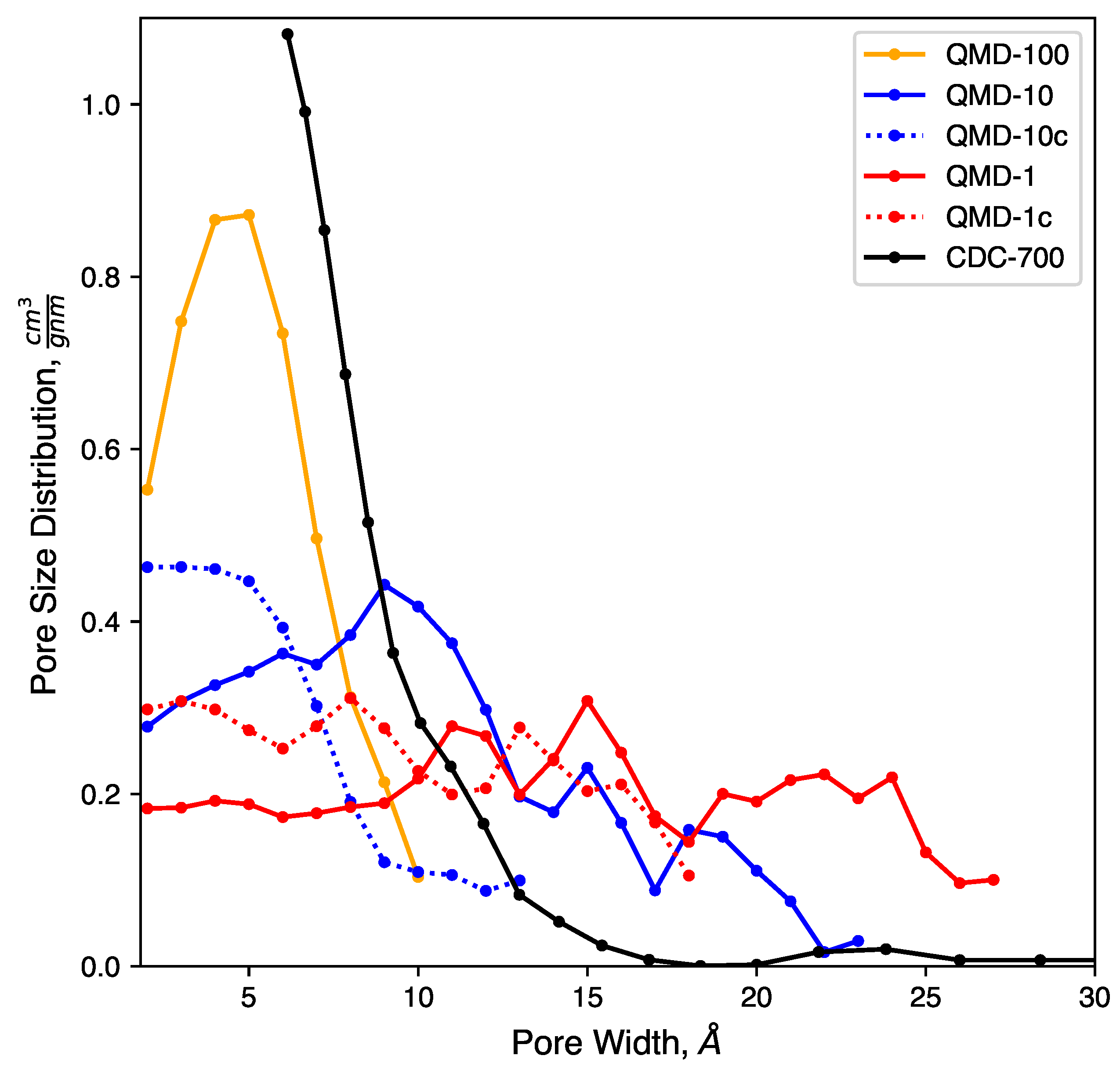
Clear trends with respect to quench rate are observed: faster quenches produce more amorphous structures and slower quenches produce more ordered structures. This is in agreement with prior QMD studies of amorphous carbons [53,55,71]. Shown in Figure 2a, a quench rate of 100 K   p s 1 generates a highly amorphous structure with many stringy domains and few rings. Only a small number of rings are found, as quantified in Figure 4, and no specific ring size dominates the distributions. This low quantity prevents the formation of large sheets with graphitic features, which had been observed in CDCs synthesized at high temperature and that had exhibited prominent graphitic domains. The pore size distribution (Figure 3) shows that all porosity is below 1 n m and most pores are approximately 0.5 n m . Despite this, the observed nature of the carbon bonding indicates that these nanopores are not necessarily directly representative of those found in synthesized CDCs.
Slowing the quench rate gives more time for rings to form, as seen in Figure 2b, and some networks begin to reach the size of several rings and resemble small graphene-like sheets. Rings are mostly hexagonal, but a number of Stone–Wales and similar defects are observed. Stringy domains are not eliminated but appear at notably smaller frequency. The overall structure remains amorphous, but the greater quality of ring networks generates pores of greater definition. These pores are also larger, as seen in Figure 3. Many pores are sub-nanometer, but there is also a broad shoulder between 1 and 2 n m .
As shown in Figure 2c, further reducing the quench rate by a factor of 10 to 1 K   p s 1 generates a more ordered structure. Most carbon atoms assemble into hexagonal rings, which aggregate into large, curved sheets that enclose nanopores. Some sheets collapse onto each other and form domains reminiscent of [ 002 ] stacking in graphite, but most sheets are single-layer and comprise pore walls. These pores exhibit a wider size distribution. While a fraction of pores is in the subnanometer diameter range, Figure 3 shows similar quantities of pores up to 2.5 n m in size. This emergence of larger pores with decreasing quench rate has been observed in previous QMD studies [55,71,92]. It bears repeating that quench rate in simulation lacks a direct physical analog; therefore, this trend cannot directly be attributed to any features of synthesis via halogen etching despite how physically realistic the generated structures may be.
In summary, slower quenches produce structures with physically realistic carbon bonding but larger pores. Because the small pore size of CDCs gives rise to many important physical properties, it is worth attempting to modify the structures generated from slow quenches to have smaller pores. To this end, we applied a post-quench compression step to the QMD-10 and QMD-1 structures via NPT simulations at 20,000 atm and 3000 K , generating structures QMD-10c (Figure 2d) and QMD-1c (Figure 2e).
Comparisons between Figure 2b,d and Figure 2c,e shows that the compression step qualitatively decreases pore sizes, particularly of larger pores. Some rearrangement is observed in Figure 2d, but for the most part, and particularly in Figure 2e, pores are modified without collapsing existing pores and/or forming new ones. Qualitative visual observations do not show any alterations of ring bonding. Thus, the combination of ReaxFF with a post-compression step results in pore size distributions that more closely match experiments as well as a recent study that generated CDCs using the EDIP force field and, rather than QMD, annealing of a system after removal of metal atoms from a carbide lattice [65]. Specifically, this compression step combines properties of QMD-generated models at different quench rates: the local bonding structure is dominated by six-membered rings, but the pore size distribution does not largely extend in the mesoporous regime.

4.2.1. Pore Size Distribution

Pore size distributions of QMD samples are shown in Figure 3. Consistent with previous QMD studies [55,92], the pore size and dispersity increase with slower quench rates. The compression steps (samples QMD-10c and QMD-1c) are shown to quantitatively increase the population of sub-nanometer pores and, to a lesser extent, decrease the dispersity. Although the post-quenching compression step fails to fully reach the monodisperse sub-nanometer target, agreement with the experimental pore size distribution is improved, most notably for QMD-10c.
We note that, while experimental characterization results demonstrate a strong predominance of sub-nanometer pores, a small shoulder at 1–1.5 n m and a small peak between 2.0 and 2.5 n m are observed. As such, the larger pore size distributions observed in some of our or systems may indeed be realistic. However, they may form in higher frequency than in experimentally produced CDCs.

4.2.2. Ring Size Distributions

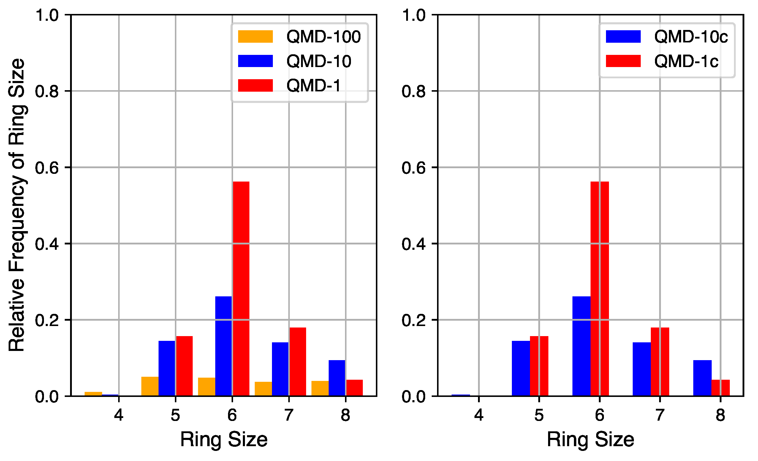
Although a robust quantification of the number of non-hexagonal rings is not currently accessible via empirical characterization of experimental systems, it can be quantified in simulation. The relative quantities of rings of sizes 4 through 8 in QMD-generated structures are shown in Figure 4. Ring counts are normalized to the number of hexagonal rings in a fully graphitic sample of the same size (10,000 rings in these 20,000 atom systems). By comparing compressed and non-compressed samples, the compression step is shown to have a small impact on the number of rings but little impact on the distribution. On the left are ring size distributions from samples produced by QMD alone and on the right are ring size distributions from samples that also underwent a post-quench compression step.
The quench rate is shown to have a significant impact on the quantity of ring formation and type of rings formed. At the fastest quench rate, few rings are formed with no particular size dominating the distribution. At the slowest quench rate, the total number of rings approaches the graphitic limit and hexagonal rings are the most common. The ring size distribution for the samples of medium quench rate mixes properties of the limits: the total number of rings is large and hexagonal rings are the most common, but not by a large margin. For all QMD-generated structures, the number of four-membered rings is negligible and the number of eight-membered rings is non-zero but not significant. For all quench rates, the number of five- and seven-membered rings is similar, indicating that their existence may be structurally coupled.
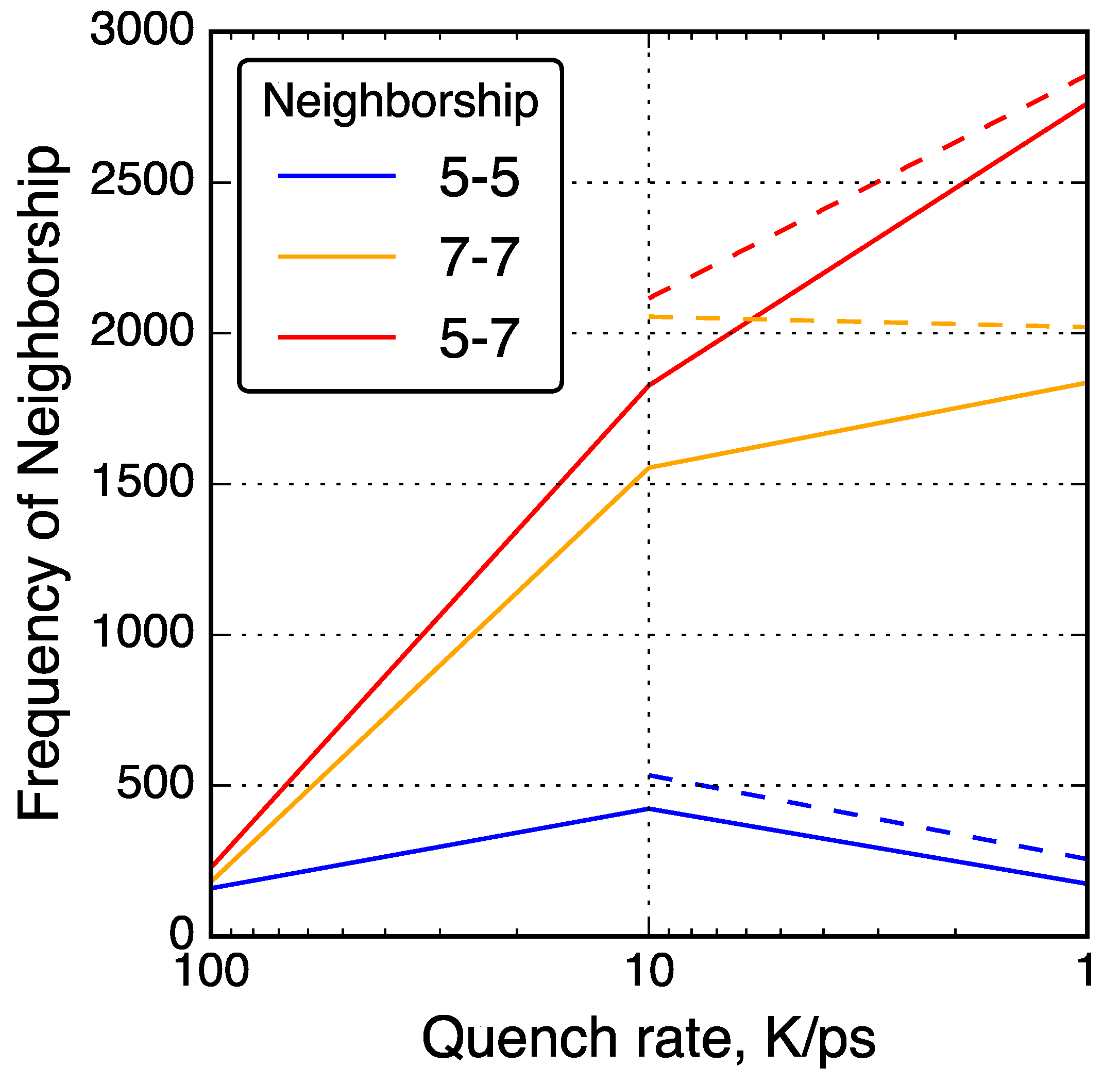
To further investigate the relationships between non-hexagonal rings, neighbor–neighbor correlations of non-hexagonal rings were analyzed and shown in Figure 5. For example, the number of 7-membered rings neighboring a 5-membered rings was counted and shown as a ‘5-7’ neighbor type. With slower quench rate, 5-7 and 7-7 neighbor types increased in quantity while 5-5 neighbor types decreased in quantity. This trend is consistent with common graphene defects such as the Stone–Wales 55-77 defect [93] and the 555-777 divacancy [41]. Other common non-hexagonal defects found in graphene follow a consistent theme of 7-membered rings neighboring each other and 5-membered rings, but rarely 5-membered rings neighboring each other [94].

4.3. Sorptive Loading

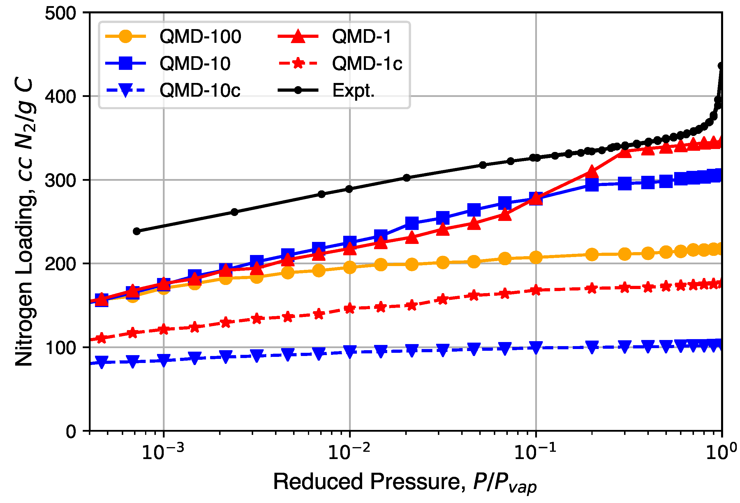
Nitrogen isotherms generated from GCMC simulation are shown in Figure 6 and compared to a representative experimental isotherm. Characteristic Type I isotherms are observed: most loading occurs at low relative pressures and little change in loading occurs at moderate relative pressures. A partial condensation phase transition is only observed in the QMD-1 sample, which is expected to be the result of mesopores. The loading spikes in experimental samples near P = P v a p are the result of larger non-porous features formed from the packing of the CDC nanoparticle and not the result of mesopores found in bulk CDC phases. The lower loadings in compressed samples compared to non-compressed samples is a result of an artificially high density, although the shapes of the isotherms are not noticeably affected.

4.4. X-Ray Total Scattering

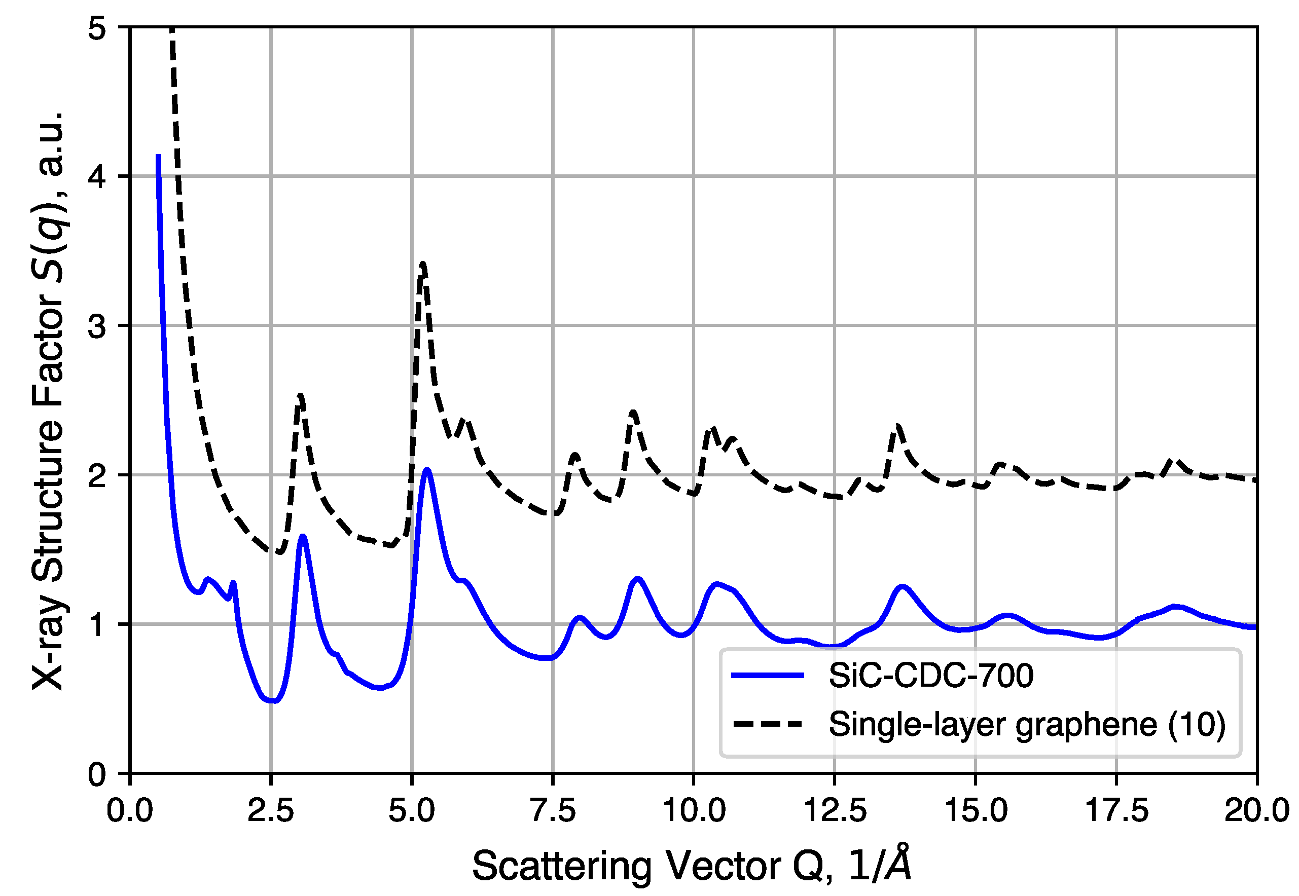
Further structural analysis relies on a synchrotron X-ray source for total scattering/pair distribution function analysis. The S ( Q ) of an annealed CDC sample is shown in Figure 7 and compared to simulated data of an ideal graphene sheet of 10 × 10 unit cells. We note here that the large intensity uptake observed in the low Q region arises from the surface scattering and pore structures present in the CDCs. Comparisons to QMD-generated structures in real space are discussed below. Most of the peaks observed in the experimental sample correspond well to the diffraction pattern of the graphene structure, the exceptions being peaks at 1.4(1) Å 1 and 1.83(2) Å 1 (∼3.43 Å and ∼4.5 Å in real space). The 1.83(2) Å 1 peak corresponds to graphite (002) reflection typically observed at 26   deg   2 θ with Cu-Kα radiation. This peak, however, is not completely resolved and sits alongside a broad diffuse peak centered at 1.4(1) Å 1 . Such features suggest the presence of poorly coordinated graphene sheets, to which this peak is attributed. In addition, as mentioned in the experimental section, the large intensity uptake at Q < 1 Å 1 by surface and/or pore structure scattering is omitted for subsequent PDF analysis.
The PDF G ( r ) is related to the RDF g ( r ) as
G ( r ) = 4 π r ρ ( g ( r ) 1 ) ;
therefore, a PDF, unlike an RDF, may fall below zero for some values of r. The length scale over which PDFs provide strong resolution (a few Å), corresponds to carbon atoms separated by a small number of bonds.
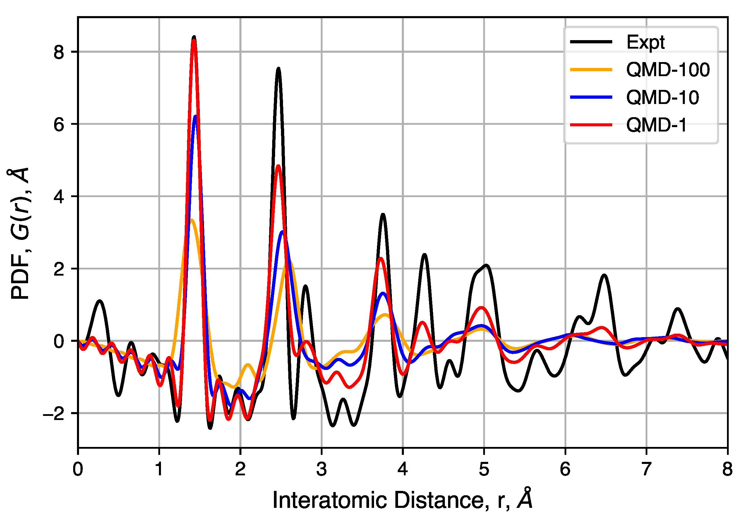
Pair distribution functions from QMD-generated structures are shown in Figure 8. The software package DISCUS [95] (Version 4.2, Michigan State University, East Lansing, MI, USA) used in these calculations in order to include the effects of some biases in the experimental apparatus, including Q m a x , Q d a m p , and Q b r o a d . For the local carbon bonding comparisons, only a small isotropic thermal displacement factor is introduced (B i s o = 0.2 Å 2 , approximately 0.05 Å mean-square displacement) because the QMD-generated structures are large enough to contain the desired static disorder. The overall intensity scale factor is also adjusted to compare with observed PDF. To maintain consistency, all simulated PDFs used the same parameters.
The peaks of these PDFs correspond well to the distances between carbons in an idealized graphene-like structure and follows previous interpretation in which no strong correlation can be observed between different sheets and/or pore walls [96,97]. The first three peaks at 1.43(2), 2.45(2) and 2.83(2) Å correspond to neighbors in a hexagonal ring and peaks at 3.75(5), 4.28(5) and 4.97(8) Å correspond to the location of carbon atoms in neighboring rings. The well-ordered nature of these peaks indicates, as expected, that hexagonal rings are favored. However, significant peak asymmetry and broadening observed at the third and further peaks do indicate the presence of non-hexagonal rings and the resulting sheet curvature effects. Together, these define the extent of structural coherence (approximately 15 Å) in the experimental PDF data. Compared to simulated PDFs, slower quenches provide better agreement with experiment, though QMD-1 is not able to totally capture graphitic ordering at distances greater than ∼5 Å. Consistent in both experimental and simulated PDFs is the general feature in peak broadening and the lack of graphite [ 002 ] correlation near 3.43 Å, the latter indicating a lack of sheet–sheet stacking despite other graphitic properties.

4.5. Effects of Initial Density

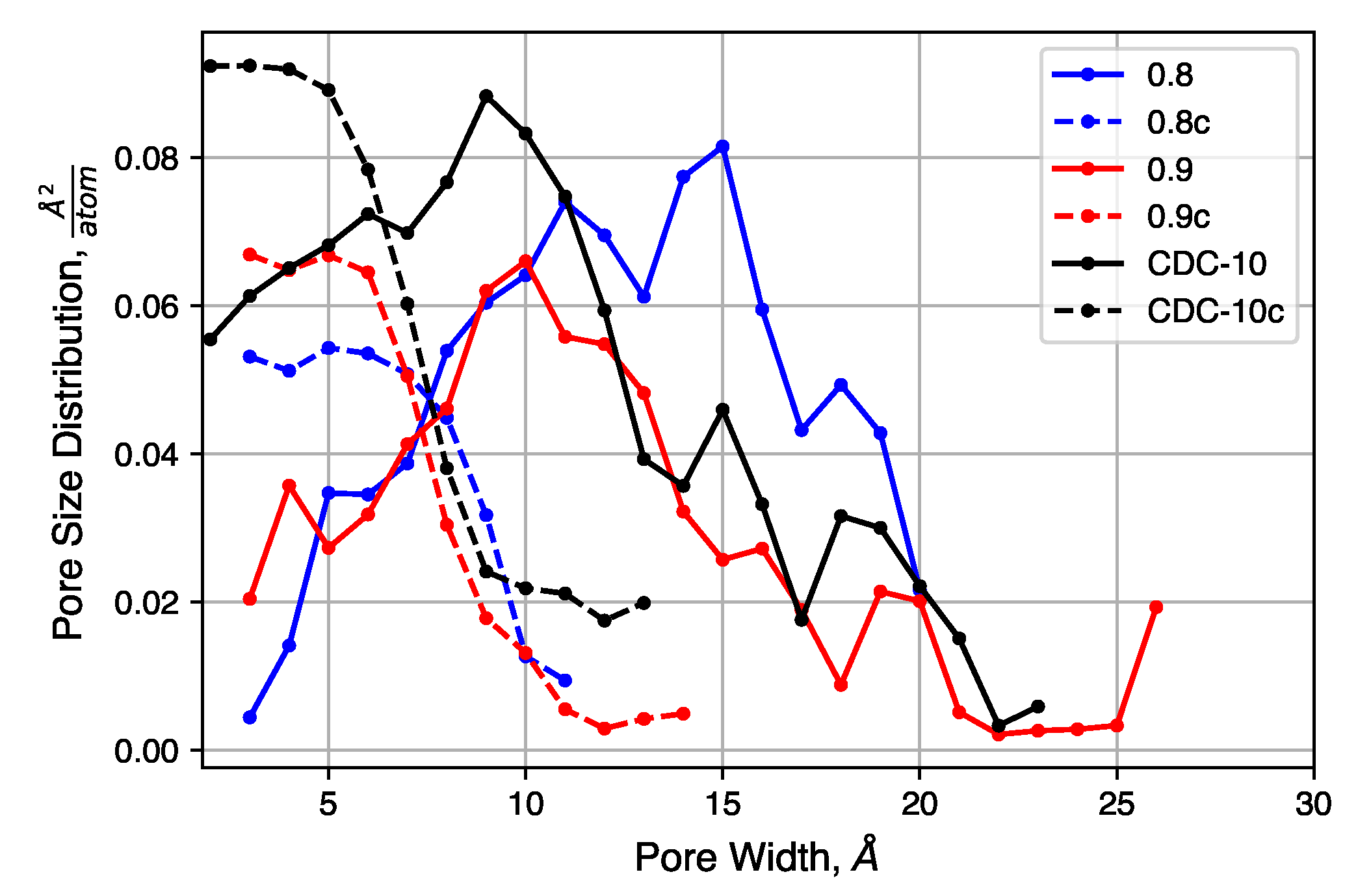
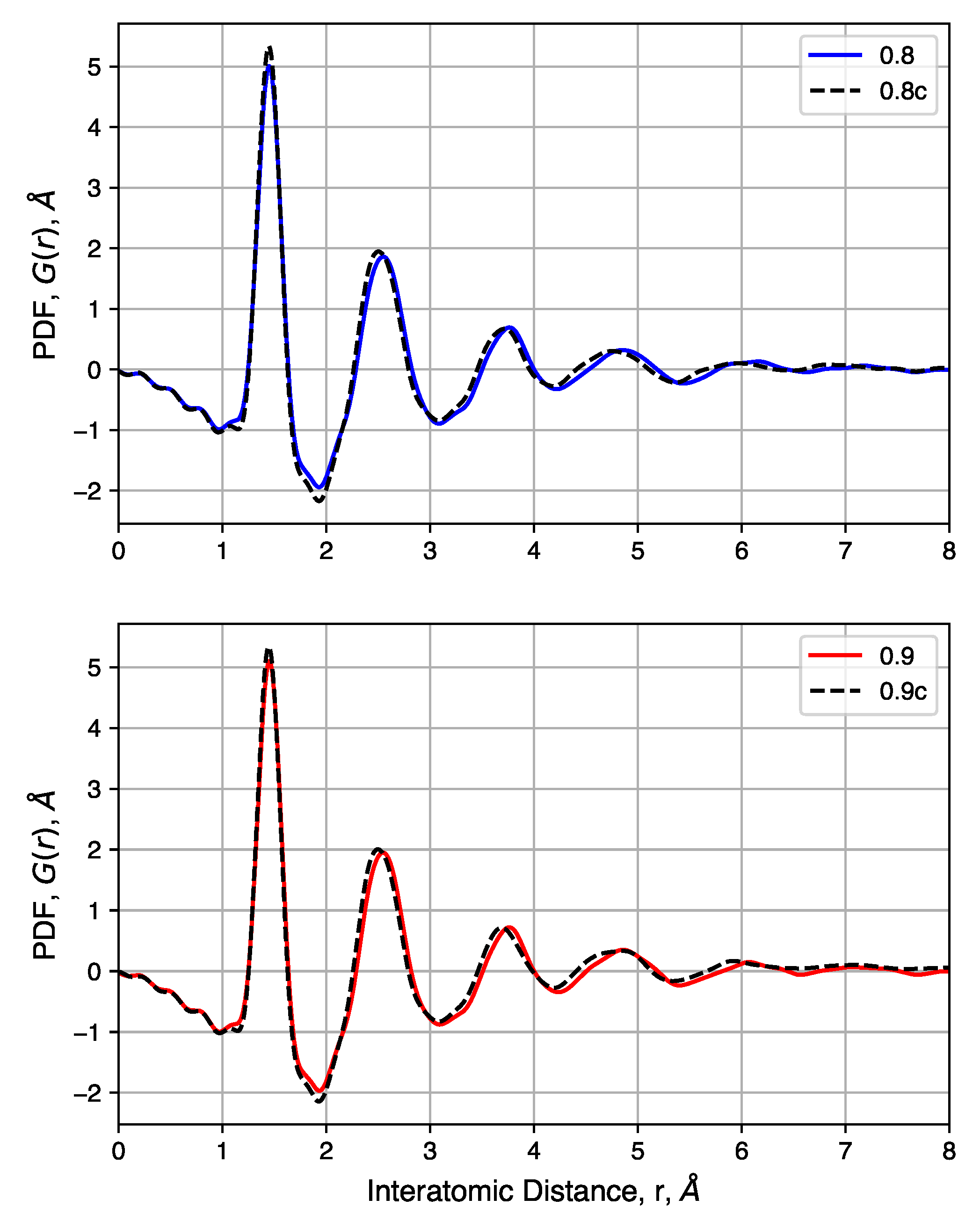
We consider the effects of initial density on the final structure. The QMD-10c sample, which has an initial density of 0.95 g   c m 3 , was considered as a reference. Simulations were performed with identical inputs with the exception of the initial density. Values of 0.8 and 0.9 g   c m 3 were considered. After compression, these two systems reached densities of 1.56 and 1.55 g   c m 3 , respectively, as compared to 1.467 g   c m 3 for the system originally at 0.95 g   c m 3 .
The pore size distributions of each of sample, before and after compression at 20,000 atm, are shown in Figure 9. Pore size distributions of samples compressed at other pressures are shown in Figure S4. For all un-compressed samples, the distribution is broad, covering the range 0.3 n m –2.0 n m . There is also a small increase in the mean pore size as the density decreases. The compressed samples, however, exhibit similar pore size distributions. Each has a peak near 0.5 n m and a shoulder that disappears near 1.0 n m . The uniformity of these distributions suggested that the initial density does not strongly impact the porosity of the structure after compression, for these relatively high density systems, as quench rate is likely to be the dominant factor for structural evolution.
We also consider the pair distribution functions of these samples, shown in Figure 10. For samples with a range of initial densities, compression has a small impact. Peak heights are not noticeably changed, but compression shifts each peak slightly to the left. This is attributed to the high pressure needed to increase the density of each sample and not differences in the nature of the carbon bonds. Comparisons of samples before and after compression show that density has no noticeable impact on the pair distribution functions. In summary, compression is shown to have negligibly small impacts on short-range carbon interactions while driving most of the pore size distribution below 1 n m .
We should note, however, that they are still quite small compared to experiments.
As shown in Figure 1, experimental samples include a variety of highly amorphous domains and features such as graphitic slit pores and single, isolated graphene sheets, in addition to other heterogeneous nanoscale domains. As a result, experimental samples will show localized variation in structure and density. Furthermore, experimental CDC samples could be thought of as a collection of individual structures comprising larger particles. The models generated here represent a separate collection of structures that may overlap with those found in experiments. Thus, prudent studies of the behavior of CDCs should consider the collective behavior of a range of nanoscale structures to better understand the resulting physical properties observed in experiments.

5. Conclusions

The use of the ReaxFF reactive force field in generating an atomistic model for carbide-derived carbons was explored using a quenched molecular dynamics (QMD) scheme. The effects of quench rate and system compression were explored. Comparisons were made to an experimental carbide-derived carbon (CDC) material with similar structural properties. These models that use ReaxFF and employ a post-quenching compression step provide clear improvement upon prior CDC models generated using QMD in terms of local bonding and pore size distribution and also closely match those recently published using a process involving removal of metal atoms from a carbide and subsequent annealing [65].
Slower quench rates and a compression step yield good agreement with experimental pore size distributions (PSDs), pair distribution functions (PDFs), and qualitative morphological features in abberation-corrected scanning transmission electron microscopy (STEM) images. The sorptive behavior closely matches CDCs and typical nanoporous adsorbents. The prevalence of non-hexagonal rings and their neighbor correlations are also explored. System compression, after the quenching step, is shown to decrease average pore size toward a sub-nanometer distribution without disrupting short-range features such as ring size. Overall, QMD-10c and QMD-1c are presented as viable atomistic models for CDCs.
Future approaches may further improve the quality of this model. Specifically, an effort that combines a QMD routine with a reverse Monte Carlo stage could improve fits to PDFs and, if a suitable error norm can be constructed, also generate more realistic PSDs. The development of highly parallelized Monte Carlo software would greatly aid in this, as the computational cost of ReaxFF or other complex potentials necessitates parallelization. If future experimental probes more accurately quantify the distribution of ring sizes, they will provide another set of target data to which a simulation routine could be tuned.
This work provides the framework for use of these structures as model adsorbents and electrodes in molecular simulation of adsorption and electrochemical capacitors, respectively. Specifically, use of these models introduces non-idealities such as pore size dispersity, surface curvature, and non-hexagonal rings.

Supplementary Materials

The following are available online at https://www.mdpi.com/2311-5629/3/4/32/s1. Figure S1: System densities over the length of compression simulations with different reference pressures; Figure S2: ADF STEM image and EEL spectra collected on a SiC-CDC sample after vacuum annealing at 700 C ; Figure S3: Raman spectrum of experimental sample; Figure S4: Pore size distributions resulting from the use of barostats with high reference pressure.

Acknowledgments

The authors thank Jeremy Palmer of The University of Houston for helpful discussions. The authors thank Katharine Page of Oak Ridge National Laboratory for aid in X-Ray scattering experiments. This research is sponsored by the Fluid Interface Reactions, Structures, and Transport (FIRST) Center, an Energy Frontier Research Center funded by the U.S. Department of Energy (DOE), Office of Science, Office of Basic Energy Sciences. This research used resources of the National Energy Research Scientific Computing Center, a DOE Office of Science User Facility supported by the Office of Science of the U.S. Department of Energy under Contract No. DE-AC02-05CH11231. Use of the Advanced Photon Source (APS) at Argonne National Laboratory (ANL) was supported through a reciprocal agreement between ORNL/SNS and the APS synchrotron facility.

Author Contributions

The design of the QMD simulations was conceived by Peter T. Cummings, Adri C. T. van Duin, and C. Heath Turner. Matthew W. Thompson carried out the QMD and GCMC simulations. Adri C. T. van Duin provided ReaxFF force field parameters. Matthew W. Thompson, C. Heath Turner, and Christopher R. Iacovella analyzed the simulations. The experimental design was conceived by Hsiu-Wen Wang, Boris Dyatkin, and Yury Gogotsi. Boris Dyatkin synthesized CDC samples and carried out nitrogen sorption experiments. Hsiu-Wen Wang and Boris Dyatkin carried out X-Ray scattering experiments. Raymond R. Unocic and Xiahan Sang carried out from ADF-STEM and EELS studies. Matthew W. Thompson, Christopher R. Iacovella, Boris Dyatkin, and Hsiu-Wen Wang wrote the manuscript. All authors reviewed the manuscript prior to submission.

Conflicts of Interest

The authors declare no conflict of interest.

References

  1. Presser, V.; Heon, M.; Gogotsi, Y. Carbide-Derived Carbons—From Porous Networks to Nanotubes and Graphene. Adv. Funct. Mater. 2011, 21, 810–833. [Google Scholar] [CrossRef]
  2. Dash, R.; Chmiola, J.; Yushin, G.; Gogotsi, Y.; Laudisio, G.; Singer, J.; Fischer, J.; Kucheyev, S.O. Titanium carbide derived nanoporous carbon for energy-related applications. Carbon 2006, 44, 2489–2497. [Google Scholar] [CrossRef]
  3. Jänes, A.; Thomberg, T.; Kurig, H.; Lust, E. Nanoscale fine-tuning of porosity of carbide-derived carbon prepared from molybdenum carbide. Carbon 2009, 47, 23–29. [Google Scholar] [CrossRef]
  4. Hoffman, E.N.; Yushin, G.; El-Raghy, T.; Gogotsi, Y.; Barsoum, M.W. Micro and mesoporosity of carbon derived from ternary and binary metal carbides. Microporous Mesoporous Mater. 2008, 112, 526–532. [Google Scholar] [CrossRef]
  5. Gogotsi, Y.; Nikitin, A.; Ye, H.; Zhou, W.; Fischer, J.E.; Yi, B.; Foley, H.C.; Barsoum, M.W. Nanoporous carbide-derived carbon with tunable pore size. Nat. Mater. 2003, 2, 591–594. [Google Scholar] [CrossRef] [PubMed]
  6. Laudisio, G.; Dash, R.K.; Singer, J.P.; Yushin, G.; Gogotsi, Y.; Fischer, J.E. Carbide-derived carbons: A comparative study of porosity based on small-angle scattering and adsorption isotherms. Langmuir 2006, 22, 8945–8950. [Google Scholar] [CrossRef] [PubMed]
  7. Osswald, S.; Chmiola, J.; Gogotsi, Y. Structural evolution of carbide-derived carbons upon vacuum annealing. Carbon 2012, 50, 4880–4886. [Google Scholar] [CrossRef]
  8. Nič, M.; Jirát, J.; Košata, B.; Jenkins, A.; McNaught, A. IUPAC Compendium of Chemical Terminology; IUPAC: Research Triagle Park, NC, USA, 2009. [Google Scholar]
  9. Chmiola, J.; Yushin, G.; Gogotsi, Y.; Portet, C.; Simon, P.; Taberna, P.L. Anomalous increase in carbon capacitance at pore sizes less than 1 nanometer. Science 2006, 313, 1760–1763. [Google Scholar] [CrossRef] [PubMed] [Green Version]
  10. Chmiola, J.; Yushin, G.; Dash, R.; Gogotsi, Y. Effect of pore size and surface area of carbide derived carbons on specific capacitance. J. Power Sources 2006, 158, 765–772. [Google Scholar] [CrossRef]
  11. Chmiola, J.; Largeot, C.; Taberna, P.L.; Simon, P.; Gogotsi, Y. Monolithic Carbide-Derived Carbon Films for Micro-Supercapacitors. Science 2010, 328, 480–483. [Google Scholar] [CrossRef] [PubMed] [Green Version]
  12. Lin, R.; Huang, P.; Ségalini, J.; Largeot, C.; Taberna, P.L.; Chmiola, J.; Gogotsi, Y.; Simon, P. Solvent effect on the ion adsorption from ionic liquid electrolyte into sub-nanometer carbon pores. Electrochim. Acta 2009, 54, 7025–7032. [Google Scholar] [CrossRef] [Green Version]
  13. Nguyen, T.X.; Bae, J.S.S.; Bhatia, S.K. Characterization and adsorption modeling of silicon carbide-derived carbons. Langmuir 2009, 25, 2121–2132. [Google Scholar] [CrossRef] [PubMed]
  14. Presser, V.; McDonough, J.; Yeon, S.H.; Gogotsi, Y. Effect of pore size on carbon dioxide sorption by carbide derived carbon. Energy Environ. Sci. 2011, 4, 3059. [Google Scholar] [CrossRef]
  15. Vakifahmetoglu, C.; Presser, V.; Yeon, S.H.; Colombo, P.; Gogotsi, Y. Enhanced hydrogen and methane gas storage of silicon oxycarbide derived carbon. Microporous Mesoporous Mater. 2011, 144, 105–112. [Google Scholar] [CrossRef]
  16. Yushin, G.; Hoffman, E.N.; Barsoum, M.W.; Gogotsi, Y.; Howell, C.A.; Sandeman, S.R.; Phillips, G.J.; Lloyd, A.W.; Mikhalovsky, S.V. Mesoporous carbide-derived carbon with porosity tuned for efficient adsorption of cytokines. Biomaterials 2006, 27, 5755–5762. [Google Scholar] [CrossRef] [PubMed]
  17. Yachamaneni, S.; Yushin, G.; Yeon, S.H.; Gogotsi, Y.; Howell, C.; Sandeman, S.; Phillips, G.; Mikhalovsky, S. Mesoporous carbide-derived carbon for cytokine removal from blood plasma. Biomaterials 2010, 31, 4789–4794. [Google Scholar] [CrossRef] [PubMed]
  18. Portet, C.; Taberna, P.L.; Simon, P.; Flahaut, E.; Laberty-Robert, C. High power density electrodes for Carbon supercapacitor applications. Electrochim. Acta 2005, 50, 4174–4181. [Google Scholar] [CrossRef] [Green Version]
  19. Gogotsi, Y.; Presser, V. Carbon Nanomaterials, 2nd ed.; CRC Press: Boca Raton, FL, USA, 2013. [Google Scholar]
  20. Simon, P.; Gogotsi, Y. Capacitive Energy Storage in Nanostructured Carbon—Electrolyte Systems. Acc. Chem. Res. 2013, 46, 1094–1103. [Google Scholar] [CrossRef] [PubMed]
  21. Vora, P.M.; Gopu, P.; Rosario-Canales, M.; Pérez, C.R.; Gogotsi, Y.; Santiago-Avilés, J.J.; Kikkawa, J.M. Correlating magnetotransport and diamagnetism of sp2-bonded carbon networks through the metal-insulator transition. Phys. Rev. B 2011, 84, 155114. [Google Scholar] [CrossRef]
  22. Pak, A.J.; Paek, E.; Hwang, G.S. Tailoring the performance of graphene-based supercapacitors using topological defects: A theoretical assessment. Carbon 2014, 68, 734–741. [Google Scholar] [CrossRef]
  23. Xing, L.; Vatamanu, J.; Borodin, O.; Bedrov, D. On the atomistic nature of capacitance enhancement generated by ionic liquid electrolyte confined in subnanometer pores. J. Phys. Chem. Lett. 2013, 4, 132–140. [Google Scholar] [CrossRef] [PubMed]
  24. Faber, K.; Badaczewski, F.; Oschatz, M.; Mondin, G.; Nickel, W.; Kaskel, S.; Smarsly, B.M. In-depth investigation of the carbon microstructure of silicon carbide-derived carbons by wide-angle X-ray scattering. J. Phys. Chem. C 2014, 118, 15705–15715. [Google Scholar] [CrossRef]
  25. Zhan, C.; Neal, J.N.; Wu, J.; Jiang, D.E. Quantum Effects on the Capacitance of Graphene-Based Electrodes. J. Phys. Chem. C 2015, 119, 22297–22303. [Google Scholar] [CrossRef]
  26. Portet, C.; Kazachkin, D.; Osswald, S.; Gogotsi, Y.; Borguet, E. Impact of synthesis conditions on surface chemistry and structure of carbide-derived carbons. Thermochim. Acta 2010, 497, 137–142. [Google Scholar] [CrossRef]
  27. Dyatkin, B.; Mamontov, E.; Cook, K.M.; Gogotsi, Y. Capacitance, charge dynamics, and electrolyte-surface interactions in functionalized carbide-derived carbon electrodes. Prog. Nat. Sci. Mater. Int. 2015, 25, 631–641. [Google Scholar] [CrossRef]
  28. Ewert, J.K.; Weingarth, D.; Denner, C.; Friedrich, M.; Zeiger, M.; Schreiber, A.; Jäckel, N.; Presser, V.; Kempe, R. Enhanced capacitance of nitrogen-doped hierarchically porous carbide-derived carbon in matched ionic liquids. J. Mater. Chem. A 2015, 3, 18906–18912. [Google Scholar] [CrossRef]
  29. Pinkert, K.; Oschatz, M.; Borchardt, L.; Klose, M.; Zier, M.; Nickel, W.; Giebeler, L.; Oswald, S.; Kaskel, S.; Eckert, J. Role of Surface Functional Groups in Ordered Mesoporous Carbide-Derived Carbon/Ionic Liquid Electrolyte Double-Layer Capacitor Interfaces. ACS Appl. Mater. Interfaces 2014, 6, 2922–2928. [Google Scholar] [CrossRef] [PubMed]
  30. Gor, G.Y.; Thommes, M.; Cychosz, K.A.; Neimark, A.V. Quenched solid density functional theory method for characterization of mesoporous carbons by nitrogen adsorption. Carbon 2012, 50, 1583–1590. [Google Scholar] [CrossRef]
  31. Kurig, H.; Russina, M.; Tallo, I.; Siebenbürger, M.; Romann, T.; Lust, E. The suitability of infinite slit-shaped pore model to describe the pores in highly porous carbon materials. Carbon 2016, 100, 617–624. [Google Scholar] [CrossRef]
  32. Kondrat, S.; Kornyshev, A.A. Pressing a spring: What does it take to maximize the energy storage in nanoporous supercapacitors? Nanoscale Horiz. 2016, 1, 45–52. [Google Scholar] [CrossRef]
  33. Pak, A.J.; Hwang, G.S. Molecular Insights into the Complex Relationship between Capacitance and Pore Morphology in Nanoporous Carbon-based Supercapacitors. ACS Appl. Mater. Interfaces 2016, 8, 34659–34667. [Google Scholar] [CrossRef] [PubMed]
  34. Striolo, A.; Chialvo, A.A.; Cummings, P.T.; Gubbins, K.E. Water Adsorption in Carbon-Slit Nanopores. Langmuir 2003, 19, 8583–8591. [Google Scholar] [CrossRef]
  35. Wang, Q.; Johnson, J.K. Molecular simulation of hydrogen adsorption in single-walled carbon nanotubes and idealized carbon slit pores. J. Chem. Phys. 1999, 110, 577–586. [Google Scholar] [CrossRef]
  36. Cracknell, R.F.; Nicholson, D.; Quirke, N. A grand canonical Monte Carlo study of Lennard-Jones mixtures in slit shaped pores. Mol. Phys. 1993, 80, 885–897. [Google Scholar] [CrossRef]
  37. He, Y.; Huang, J.; Sumpter, B.G.; Kornyshev, A.A.; Qiao, R. Dynamic Charge Storage in Ionic Liquids-filled Nanopores: Insight from a Computational Cyclic Voltammetry Study. J. Phys. Chem. Lett. 2015, 6, 22–30. [Google Scholar] [CrossRef] [PubMed]
  38. Kondrat, S.; Wu, P.; Qiao, R.; Kornyshev, A.A. Accelerating charging dynamics in subnanometre pores. Nat. Mater. 2014, 13, 387–393. [Google Scholar] [CrossRef] [PubMed]
  39. Miyahara, M.; Gubbins, K.E. Freezing/melting phenomena for Lennard-Jones methane in slit pores: A Monte Carlo study. J. Chem. Phys. 1997, 106, 2865–2880. [Google Scholar] [CrossRef]
  40. Feng, G.; Qiao, R.; Huang, J.; Dai, S.; Sumpter, B.G.; Meunier, V. The importance of ion size and electrode curvature on electrical double layers in ionic liquids. Phys. Chem. Chem. Phys. 2011, 13, 1152–1161. [Google Scholar] [CrossRef] [PubMed]
  41. Wood, B.C.; Ogitsu, T.; Otani, M.; Biener, J. First-Principles-Inspired Design Strategies for Graphene-Based Supercapacitor Electrodes. J. Phys. Chem. C 2014, 118, 4–15. [Google Scholar] [CrossRef]
  42. Palmer, J.C.; Moore, J.D.; Brennan, J.K.; Gubbins, K.E. Simulating local adsorption isotherms in structurally complex porous materials: A direct assessment of the slit pore model. J. Phys. Chem. Lett. 2011, 2, 165–169. [Google Scholar] [CrossRef]
  43. Bandaru, P.; Yamada, H.; Narayanan, R.; Hoefer, M. Charge transfer and storage in nanostructures. Mater. Sci. Eng. R Rep. 2015, 96, 1–69. [Google Scholar] [CrossRef]
  44. McGreevy, R.L.; Pusztai, L. Reverse Monte Carlo Simulation: A New Technique for the Determination of Disordered Structures. Mol. Simul. 1988, 1, 359–367. [Google Scholar] [CrossRef]
  45. Duane, S.; Kennedy, A.; Pendleton, B.J.; Roweth, D. Hybrid Monte Carlo. Phys. Lett. B 1987, 195, 216–222. [Google Scholar] [CrossRef]
  46. Pikunic, J.; Clinard, C.; Cohaut, N.; Gubbins, K.E.; Guet, J.M.; Pellenq, R.J.M.; Rannou, I.; Rouzaud, J.N. Structural Modeling of Porous Carbons: Constrained Reverse Monte Carlo Method. Langmuir 2003, 19, 8565–8582. [Google Scholar] [CrossRef]
  47. Zetterström, P.; Urbonaite, S.; Lindberg, F.; Delaplane, R.G.; Leis, J.; Svensson, G. Reverse Monte Carlo studies of nanoporous carbon from TiC. J. Phys. Condens. Matter 2005, 17, 3509–3524. [Google Scholar] [CrossRef]
  48. Palmer, J.C.; Brennan, J.K.; Hurley, M.; Balboa, A.; Gubbins, K.E. Detailed structural models for activated carbons from molecular simulation. Carbon 2009, 47, 2904–2913. [Google Scholar] [CrossRef]
  49. Farmahini, A.H.; Opletal, G.; Bhatia, S.K. Structural Modelling of Silicon Carbide-Derived Nanoporous Carbon by Hybrid Reverse Monte Carlo Simulation. J. Phys. Chem. C 2013, 117, 14081–14094. [Google Scholar] [CrossRef]
  50. Jedlovszky, P.; Bakó, I.; Pálinkás, G.; Radnai, T.; Soper, A.K. Investigation of the uniqueness of the reverse Monte Carlo method: Studies on liquid water. J. Chem. Phys. 1996, 105, 245–254. [Google Scholar] [CrossRef]
  51. Soper, A. Empirical potential Monte Carlo simulation of fluid structure. Chem. Phys. 1996, 202, 295–306. [Google Scholar] [CrossRef]
  52. Palmer, J.C.; Gubbins, K.E. Atomistic models for disordered nanoporous carbons using reactive force fields. Microporous Mesoporous Mater. 2012, 154, 24–37. [Google Scholar] [CrossRef]
  53. Shi, Y. A mimetic porous carbon model by quench molecular dynamics simulation. J. Chem. Phys. 2008, 128, 234707. [Google Scholar]
  54. Powles, R.; Marks, N.; Lau, D. Self-assembly of 2-bonded carbon nanostructures from amorphous precursors. Phys. Rev. B 2009, 79, 1–11. [Google Scholar] [CrossRef]
  55. Palmer, J.C.; Llobet, A.; Yeon, S.H.H.; Fischer, J.E.; Shi, Y.; Gogotsi, Y.; Gubbins, K.E. Modeling the structural evolution of carbide-derived carbons using quenched molecular dynamics. Carbon 2010, 48, 1116–1123. [Google Scholar] [CrossRef]
  56. Garofalini, S.H. Molecular dynamics simulation of the frequency spectrum of amorphous silica. J. Chem. Phys. 1982, 76, 3189. [Google Scholar] [CrossRef]
  57. Gelb, L.D.; Gubbins, K.E. Pore Size Distributions in Porous Glasses: A Computer Simulation Study. Langmuir 1999, 15, 305–308. [Google Scholar] [CrossRef]
  58. Litton, D.A.; Garofalini, S.H. Modeling of hydrophilic wafer bonding by molecular dynamics simulations. J. Appl. Phys. 2001, 89, 6013–6023. [Google Scholar] [CrossRef]
  59. Kluge, M.D.; Ray, J.R.; Rahman, A. Amorphous-silicon formation by rapid quenching: A molecular-dynamics study. Phys. Rev. B 1987, 36, 4234–4237. [Google Scholar] [CrossRef]
  60. Ding, K.; Andersen, H.C. Molecular-dynamics simulation of amorphous germanium. Phys. Rev. B 1986, 34, 6987–6991. [Google Scholar] [CrossRef]
  61. Stuart, S.J.; Tutein, A.B.; Harrison, J.A. A reactive potential for hydrocarbons with intermolecular interactions. J. Chem. Phys. 2000, 112, 6472–6486. [Google Scholar] [CrossRef]
  62. Marks, N.A. Generalizing the environment-dependent interaction potential for carbon. Phys. Rev. B 2000, 63, 035401. [Google Scholar] [CrossRef]
  63. Tersoff, J. Modeling solid-state chemistry: Interatomic potentials for multicomponent systems. Phys. Rev. B 1989, 39, 5566–5568. [Google Scholar] [CrossRef]
  64. Mi, X.; Shi, Y. Topological defects in nanoporous carbon. Carbon 2013, 60, 202–214. [Google Scholar] [CrossRef]
  65. De Tomas, C.; Suarez-Martinez, I.; Vallejos-Burgos, F.; López, M.J.; Kaneko, K.; Marks, N.A. Structural prediction of graphitization and porosity in carbide-derived carbons. Carbon 2017, 119, 1–9. [Google Scholar] [CrossRef]
  66. Schweizer, S.; Meissner, R.; Amkreutz, M.; Thiel, K.; Schiffels, P.; Landwehr, J.; Etzold, B.J.; Hill, J.R. Molecular Modeling of Microporous Structures of Carbide-Derived Carbon Based Supercapacitors. J. Phys. Chem. C 2017, 121, 7221–7231. [Google Scholar] [CrossRef]
  67. De Tomas, C.; Suarez-Martinez, I.; Marks, N.A. Graphitization of amorphous carbons: A comparative study of interatomic potentials. Carbon 2016, 109, 681–693. [Google Scholar] [CrossRef]
  68. Welz, S.; McNallan, M.J.; Gogotsi, Y. Carbon structures in silicon carbide derived carbon. J. Mater. Process. Technol. 2006, 179, 11–22. [Google Scholar] [CrossRef]
  69. Van Duin, A.C.T.; Dasgupta, S.; Lorant, F.; Goddard, W.A. ReaxFF: A Reactive Force Field for Hydrocarbons. J. Phys. Chem. A 2001, 105, 9396–9409. [Google Scholar] [CrossRef]
  70. Srinivasan, S.G.; van Duin, A.C.T.; Ganesh, P. Development of a ReaxFF Potential for Carbon Condensed Phases and Its Application to the Thermal Fragmentation of a Large Fullerene. J. Phys. Chem. A 2015, 119, 571–580. [Google Scholar] [CrossRef] [PubMed]
  71. Ranganathan, R.; Rokkam, S.; Desai, T.; Keblinski, P. Generation of amorphous carbon models using liquid quench method: A reactive molecular dynamics study. Carbon 2017, 113, 87–99. [Google Scholar] [CrossRef]
  72. Aktulga, H.M.; Fogarty, J.C.; Pandit, S.A.; Grama, A.Y. Parallel reactive molecular dynamics: Numerical methods and algorithmic techniques. Parallel Comput. 2012, 38, 245–259. [Google Scholar] [CrossRef]
  73. Chenoweth, K.; van Duin, A.C.T.; Goddard, W.A. ReaxFF Reactive Force Field for Molecular Dynamics Simulations of Hydrocarbon Oxidation. J. Phys. Chem. A 2008, 112, 1040–1053. [Google Scholar] [CrossRef] [PubMed]
  74. Plimpton, S. Fast Parallel Algorithms for Short-Range Molecular Dynamics. J. Comput. Phys. 1995, 117, 1–19. [Google Scholar] [CrossRef]
  75. Chenoweth, K.; van Duin, A.C.T.; Dasgupta, S.; Goddard, W.A., III. Initiation Mechanisms and Kinetics of Pyrolysis and Combustion of JP-10 Hydrocarbon Jet Fuel. J. Phys. Chem. A 2009, 113, 1740–1746. [Google Scholar] [CrossRef] [PubMed]
  76. Castro-Marcano, F.; Kamat, A.M.; Russo, M.F.; van Duin, A.C.T.; Mathews, J.P. Combustion of an Illinois No. 6 coal char simulated using an atomistic char representation and the ReaxFF reactive force field. Combust. Flame 2012, 159, 1272–1285. [Google Scholar] [CrossRef]
  77. Bundy, F. Pressure-temperature phase diagram of elemental carbon. Phys. A Stat. Mech. Appl. 1989, 156, 169–178. [Google Scholar]
  78. Bundy, F.; Bassett, W.; Weathers, M.; Hemley, R.; Mao, H.; Goncharov, A. The pressure-temperature phase and transformation diagram for carbon. updated through 1994. Carbon 1996, 34, 141–153. [Google Scholar] [CrossRef]
  79. Shinoda, W.; Shiga, M.; Mikami, M. Rapid estimation of elastic constants by molecular dynamics simulation under constant stress. Phys. Rev. B Condens. Matter Mater. Phys. 2004, 69, 16–18. [Google Scholar] [CrossRef]
  80. Martyna, G.J.; Tobias, D.J.; Klein, M.L. Constant pressure molecular dynamics algorithms. J. Chem. Phys. 1994, 101, 4177–4189. [Google Scholar] [CrossRef]
  81. Parrinello, M.; Rahman, A. Polymorphic transitions in single crystals: A new molecular dynamics method. J. Appl. Phys. 1981, 52, 7182–7190. [Google Scholar] [CrossRef]
  82. Tsai, W.Y.; Gao, P.C.; Daffos, B.; Taberna, P.L.; Perez, C.R.; Gogotsi, Y.; Favier, F.; Simon, P. Ordered mesoporous silicon carbide-derived carbon for high-power supercapacitors. Electrochem. Commun. 2013, 34, 109–112. [Google Scholar] [CrossRef] [Green Version]
  83. Dyatkin, B.; Gogotsi, Y. Effects of structural disorder and surface chemistry on electric conductivity and capacitance of porous carbon electrodes. Faraday Discuss. 2014, 172, 139–162. [Google Scholar] [CrossRef] [PubMed]
  84. Brunauer, S.; Emmett, P.H.; Teller, E. Adsorption of Gases in Multimolecular Layers. J. Am. Chem. Soc. 1938, 60, 309–319. [Google Scholar] [CrossRef]
  85. Caguiat, J.N.; Kirk, D.W.; Jia, C.Q. Uncertainties in characterization of nanoporous carbons using density functional theory-based gas physisorption. Carbon 2014, 72, 47–56. [Google Scholar] [CrossRef]
  86. Hammersley, A.P.; Svensson, S.O.; Hanfland, M.; Fitch, A.N.; Hausermann, D. Two-dimensional detector software: From real detector to idealised image or two-theta scan. High Press. Res. 1996, 14, 235–248. [Google Scholar] [CrossRef]
  87. Qiu, X.; Thompson, J.W.; Billinge, S.J.L. PDFgetX2: A GUI-driven program to obtain the pair distribution function from X-ray powder diffraction data. J. Appl. Crystallogr. 2004, 37, 678. [Google Scholar] [CrossRef]
  88. Chupas, P.J.; Qiu, X.; Hanson, J.C.; Lee, P.L.; Grey, C.P.; Billinge, S.J.L. Rapid-acquisition pair distribution function (RA-PDF) analysis. J. Appl. Crystallogr. 2003, 36, 1342–1347. [Google Scholar] [CrossRef]
  89. Farrow, C.L.; Juhas, P.; Liu, J.W.; Bryndin, D.; Božin, E.S.; Bloch, J.; Proffen, T.; Billinge, S.J.L. PDFfit2 and PDFgui: computer programs for studying nanostructure in crystals. J. Phys. Condens. Matter 2007, 19, 335219. [Google Scholar] [CrossRef] [PubMed]
  90. Krivanek, O.L.; Chisholm, M.F.; Nicolosi, V.; Pennycook, T.J.; Corbin, G.J.; Dellby, N.; Murfitt, M.F.; Own, C.S.; Szilagyi, Z.S.; Oxley, M.P.; et al. Atom-by-atom structural and chemical analysis by annular dark-field electron microscopy. Nature 2010, 464, 571–574. [Google Scholar] [CrossRef] [PubMed]
  91. Voyles, P.M.; Muller, D.A.; Grazul, J.L.; Citrin, P.H.; Gossmann, H.J.L. Atomic-scale imaging of individual dopant atoms and clusters in highly n-type bulk Si. Nature 2002, 416, 826–829. [Google Scholar] [CrossRef] [PubMed]
  92. Gelb, L.D.; Gubbins, K.E. Characterization of Porous Glasses: Simulation Models, Adsorption Isotherms, and the Brunauer-Emmett-Teller Analysis Method. Langmuir 1998, 14, 2097–2111. [Google Scholar] [CrossRef]
  93. Stone, A.J.; Wales, D.J. Theoretical studies of icosahedral C60 and some related species. Chem. Phys. Lett. 1986, 128, 501–503. [Google Scholar] [CrossRef]
  94. Meyer, J.C.; Kisielowski, C.; Erni, R.; Rossell, M.D.; Crommie, M.F.; Zettl, A. Direct imaging of lattice atoms and topological defects in graphene membranes. Nano Lett. 2008, 8, 3582–3586. [Google Scholar] [CrossRef] [PubMed]
  95. Proffen, T.; Neder, R.B. DISCUS: A program for diffuse scattering and defect-structure simulation. J. Appl. Crystallogr. 1997, 30, 171–175. [Google Scholar] [CrossRef]
  96. Petkov, R.G.; Difrancesco, S.J.L.V. Local structure of nanoporous carbons. Philos. Mag. B 1999, 79, 1519–1530. [Google Scholar] [CrossRef]
  97. Forse, A.C.; Merlet, C.; Allan, P.K.; Humphreys, E.K.; Griffin, J.M.; Aslan, M.; Zeiger, M.; Presser, V.; Gogotsi, Y.; Grey, C.P. New Insights into the Structure of Nanoporous Carbons from NMR, Raman, and Pair Distribution Function Analysis. Chem. Mater. 2015, 27, 6848–6857. [Google Scholar] [CrossRef]
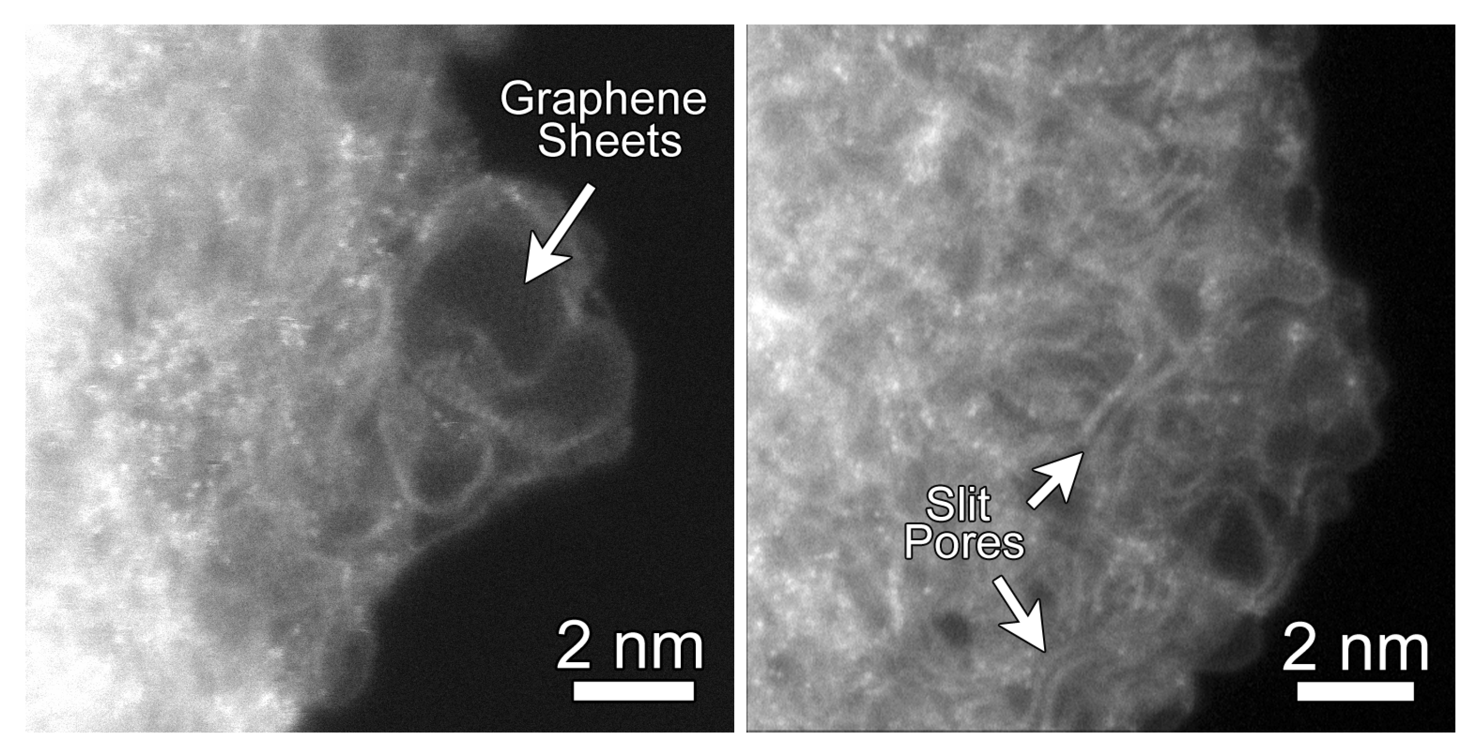
Figure 1. Representative Annular Dark-Field (ADF) Abberation-Corrected Scanning Transmission Electron Microscopy (STEM) images of carbide-derived carbons (CDCs) from experiment. CDC samples were subjected to heat treatment at 700 C for 11 h. (Left) regions of highly-curved graphene sheets; (Right) regions where the graphene sheets form slit-like configurations. The bright atoms with the CDC structure are residual silicon atoms as confirmed through Electron Energy Loss Spectroscopy (EELS).
Carbon 03 00032 g001
Figure 2. Sample structures produced via quenched molecular dynamics (QMD) at quench rates and comparison to STEM of Si-CDC from experiment. Simulation boxes are between 6.5 and 7.5 n m in length and include 20,000 atoms. Each scale bar is 10 Å or 1 n m long.
Carbon 03 00032 g002
Figure 3. Pore size distributions of model samples compared to experiments.
Carbon 03 00032 g003
Figure 4. Ring size distributions of QMD-generated models.
Carbon 03 00032 g004
Figure 5. Neighbor–neighbor relationships between 5- and 7-membered rings in QMD-generated models. Solid lines connect data from simulations without post-quenching compression and dashed lines connect data from simulations with post-quenching compression.
Carbon 03 00032 g005
Figure 6. Nitrogen isotherms generated from grand canonical Monte Carlo (GCMC) simulation in comparison to experimental isotherms.
Carbon 03 00032 g006
Figure 7. Comparison between experimental structure factor of CDC and simulated data of single graphene layer (10 × 10 unit cells).
Carbon 03 00032 g007
Figure 8. Experimental and simulated pair distributed functions (PDFs) for three QMD-generated structures. Corrections used in the DISCUS software result in some noise in the region of r < 1 nm, whereas a corresponding radial distribution function (RDF) would have only zero values.
Carbon 03 00032 g008
Figure 9. Pore size distributions of samples with decreased initial density, before and after compression.
Carbon 03 00032 g009
Figure 10. Pair distribution functions of samples with decreased initial density, before and after compression.
Carbon 03 00032 g010
Table 1. Summary of sample structures. Models are named ‘QMD-x’ where ‘x’ is the quench rate used to produce it (in units of 1 K p s 1 −100 K p s 1 ). A ‘c’ is appended to the name if a post-quench compression step was included. Q: Quench rate, K   p s 1 ; p ¯ : mean pore size, n m ; L: Box length, n m ; ρ : Particle density, g   c m 3 .
SampleQ, Kps 1 p ¯ , nmL, nm ρ , gcm 3 Compression
QMD-1001000.507.4880.950No
QMD-10100.977.4880.950No
QMD-10c100.566.4891.467Yes
QMD-111.407.4880.950No
QMD-1c10.916.7331.311Yes