
Article

Modeling of CO2-Based Fischer–Tropsch Synthesis over a Cu/Zn/K-Promoted Fe Catalyst: Influence of Reaction Kinetics and Multi-Fixed-Bed Reactor Design

Chair of Chemical Engineering, Center of Energy Technology, Faculty of Engineering, University of Bayreuth, Universitätsstraße 30, 95447 Bayreuth, Germany
*
Author to whom correspondence should be addressed.
Submission received: 7 August 2026 / Revised: 2 September 2026 / Accepted: 4 September 2026 / Published: 9 September 2026
(This article belongs to the Special Issue Advanced Catalysis for CO2 Conversion and Utilization)

Abstract

CO2 hydrogenation by reverse water–gas shift (RWGS) directly combined with subsequent Fischer–Tropsch synthesis (FTS) in a single fixed-bed reactor represents a promising route for converting renewable hydrogen and captured carbon dioxide into hydrocarbons. However, the attainable CO2 conversion is limited by thermodynamic constraints of the RWGS, product inhibition of FTS, and intraparticle diffusion limitations. In the present work, intrinsic and effective reaction models were developed for a potassium-promoted FeCuZnK catalyst to investigate the interaction between intrinsic catalyst kinetics and internal diffusion phenomena. An intrinsic Langmuir–Hinshelwood–Hougen–Watson (LHHW) model was established using fine catalyst particles (dp ≤ 150 µm) and subsequently extended to coarse catalyst particles (dp ≈ 2 mm) by introducing an effectiveness factor. The intrinsic model identified water as the dominant inhibiting species, whereas the already high RWGS activity of the FeCuZnK catalyst leads to a rapid approach of the thermodynamic equilibrium, indicating that an increase in activity would only provide limited improvements. The effective model accurately reproduced the behavior of technical catalyst particles and was subsequently applied to multi-reactor concepts with intermediate water removal. A five-stage reactor cascade increased the attainable CO2 conversion from approximately 55% to 85% under otherwise identical operating conditions. The results demonstrate that reactor design and water management provide greater potential for process intensification than further increases in intrinsic catalyst activity alone.

1. Introduction

The catalytic hydrogenation of CO2 to hydrocarbons is considered as a promising route for storing renewable hydrogen in chemical energy carriers and for reducing fossil carbon emissions. In particular, Fe-based catalysts are attractive for “direct” CO2 conversion to higher hydrocarbons (HCs) because they can combine the reverse water-gas shift (RWGS) reaction and Fischer–Tropsch synthesis (FTS) to higher hydrocarbons within one catalytic system and reactor, respectively, enabling the conversion of CO2 and H2 first to CO and subsequently directly to HCs [1,2,3]. This could be a clear advantage to a sequential conversion of CO2 and H2 to CO (and H2O) by RWGS at a high temperature of, e.g., 800 °C in a first reactor followed by CO-based FTS at around 250 °C in a subsequent reactor, as, e.g., discussed in [4,5] and implemented industrially by INERATEC [6].
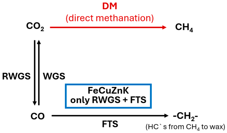
Potassium-promoted Fe catalysts are of special interest, since K suppresses the unwanted direct methanation of CO2 [7,8,9] and shifts product formation towards the RWGS–FTS pathway [10]; see Figure 1. Previous experimental investigations of promoted Fe catalysts showed that K addition decreases methane selectivity and increases the formation of CO and higher hydrocarbons (C5+) under both H2/CO and H2/CO2 conditions [11,12].
Despite this potential, the performance of Fe-based catalysts in CO2 hydrogenation is strongly limited by equilibrium constraints and by the complex interaction of parallel and consecutive reactions. In addition, the role of reaction products such as H2O and CO remains highly relevant, as both species can affect catalyst performance by shifting equilibrium and by inhibiting the reaction network. While the promoting effects of Cu, Zn, and K on activity and selectivity have been widely discussed in the literature [13,14,15], the quantitative impact of H2O and CO on the attainable CO2 conversion, as well as the consequences for reactor and process design, are still insufficiently understood, especially for Fe catalysts operating in the RWGS–FTS regime.
The present study focuses on the kinetic and transport limitations governing CO2 conversion in the coupled RWGS–FTS reaction network rather than on the detailed hydrocarbon product distribution. Accordingly, FTS is treated as a lumped reaction in the kinetic model without distinguishing between CH4, C2–C4, and C5+ hydrocarbons. To gain a deeper understanding of these effects, the present work discusses the hydrogenation of CO2 to hydrocarbons over an FeCuZnK catalyst, which was experimentally investigated with regard to the reaction kinetics of RWGS and FTS in detail in previous studies [11,12], by combining intrinsic and effective reaction modeling. It should be mentioned that the FeCuZnK sinter catalyst used in this work turned out to be the best of different investigated promoted and unpromoted Fe catalysts (including the classical commercial ARGE FeK catalyst), as only then the direct methanation of CO2 is completely suppressed [11,12]. Intrinsic simulations based on fine catalyst particles (dp < 150 µm) are used to analyze the theoretical influence of H2O and CO on CO2 conversion and CO yield and to assess the sensitivity of the system to variations in the RWGS rate constant kRWGS. The model is therefore used to quantify the factors controlling CO2 conversion within the coupled RWGS–FTS network rather than to predict the distribution or yield of individual hydrocarbon products. In particular, the effect of increasing or decreasing the intrinsic RWGS activity and the influence of inhibition by steam (inevitably formed by RWGS and FTS) on the attainable CO2 conversion is evaluated. In a second step, effective modeling is applied to coarse catalyst particles (dp = 1.6–2.0 mm) to evaluate reactor-scale behavior in a multi-reactor concept, with particular focus on the effect of targeted interstage water removal and reactor residence time on the achievable CO2 conversion.

2. Materials and Methods

2.1. Catalyst and Experimental Basis

The FeCuZnK catalyst investigated in this study is a sintered iron-based catalyst whose preparation was adapted from the procedure reported in our previous work [11]. The weight ratio of the catalyst in relation to iron is 100Fe16Cu5Zn5K and the BET surface area is about 4 m2/g.
The modified synthesis was used to produce coarse catalyst particles with a particle size of 1.6 to 2.0 mm, which served as the basis for the effective reactor-scale investigations. A detailed description of the modified preparation procedure is provided in the Supporting Information. The fine catalyst fraction used for the intrinsic kinetic experiments was obtained by crushing the coarse catalyst particles and subsequently sieving the resulting material to particle sizes below 150 µm in order to minimize internal mass-transfer limitations.
The experimental data used for model development and validation were obtained in a fixed-bed reactor operated for CO2 hydrogenation at 20 bar over a wide range of temperatures and modified residence times. In each case, the molar ratio of H2 to COx (x = 1 or 2) was three. Further details on the original catalyst preparation approach, catalyst characterization, reactor setup, analytical methods, and experimental procedures are available in [11], while the modifications applied in the present work are described in the Supplementary Material.

2.2. Reaction Network and General Modeling Assumptions

The kinetic description of CO2 hydrogenation over FeCuZnK is based on the assumption that hydrocarbons are formed via the RWGS–FTS route, i.e., CO2 is first converted to CO by the RWGS, followed by the FTS of the intermediate CO. Direct CO2 methanation was not included in the model, as methane formation via this pathway is strongly suppressed for the K-promoted FeCuZnK catalyst [11,12]. The resulting reaction network is illustrated schematically in Figure 1.
One of the first kinetic descriptions of CO2-based FTS over iron catalysts was proposed by Riedel et al. [16], who developed empirical Langmuir–Hinshelwood–Hougen–Watson (LHHW) rate expressions for the RWGS reaction, FTS and direct CO2 hydrogenation. Their RWGS model was adapted from the CO-shift kinetics originally proposed by Moe [17] and Zimmermann and Bukur [18], while the Fischer–Tropsch rate expression represents an extension of the classical LHHW formulations proposed by Anderson [19] and Dry [20]. Similar approaches have subsequently been applied by Iglesias et al. [21] and Saeidi et al. [22] for CO2 hydrogenation over potassium-promoted iron catalysts.
In the present work, a similar intrinsic kinetic model consisting of one rate expression for the RWGS reaction and one for FTS was used. The general LHHW structure proposed by Riedel et al. [16] was adopted as the basis of both equations and modified for the FeCuZnK catalyst investigated here. In contrast to the original formulation, an additional inhibition term for CO was introduced into both rate equations to account for the experimentally observed influence of CO on the coupled reaction network.
The intrinsic RWGS rate is described by
r R W G S = k R W G S c C O 2 c H 2 ( c C O   c H 2 O K e q ) 1 + a 1 , H 2 O   c H 2 O + b 1 , C O 2   c C O 2 + c 1 , C O   c C O
whereas the FTS rate is represented by
r F T S = k F T S c C O   c H 2 1 + a 2 , H 2 O   c H 2 O + b 2 , C O 2   c C O 2 + c 2 , C O   c C O
The equilibrium constant of the RWGS reaction was calculated according to Graaf et al. [23]:
K e q , R W G S = 10 ( 2073 T ( K ) + 2029 )
The inhibition parameters a n , H 2 O , b n , C O 2 and cn,CO (n = 1 or 2), together with the kinetic constants, were obtained by fitting the model to experimental data measured with fine catalyst particles (dp < 150 µm), for which internal diffusion limitations are negligible. Parameter estimation was carried out by minimizing the deviation between experimental and calculated CO2 conversion and CO yield/selectivity over the investigated temperature and residence time range. Since the catalyst preparation applied in the present study differs from that reported in our previous work, as described in Section 2.1, the kinetic parameters were determined again for the modified FeCuZnK catalyst and therefore do not correspond exactly to the values reported previously [11]. The resulting current kinetic parameters are summarized in Table 1.
Based on the validated intrinsic model, additional (theoretical) model-based studies were performed to investigate the influence of individual kinetic limitations (RWGS activity, inhibition of the rates of RWGS and FTS by steam and CO; see denominator of Equations (1) and (2)). By this means, potential directions to improve the catalyst (e.g., less inhibition by steam or more active with respect to RWGS) could be analyzed. The inhibition by H2O was analyzed by selectively varying the corresponding inhibition terms in order to quantify its influence on the attainable CO2 conversion. Furthermore, the sensitivity of the reaction network towards the RWGS kinetics was analyzed by systematically varying the RWGS rate constant kRWGS, allowing the effect of enhanced or reduced CO2 activation on the overall reactor performance to be evaluated independently of experimental constraints. Complementary model calculations addressing the influence of CO inhibition are included in the Supporting Information.
To transfer the intrinsic kinetics to technically relevant catalyst particles, an effective model was developed for FeCuZnK coarse particles with diameters of 1.6 to 2.0 mm. In contrast to the fine particles used for intrinsic parameter estimation, the coarse particles are affected by internal mass-transfer limitations due to diffusion through wax-filled pores.
The effective reaction rate of component i was therefore calculated according to
r i , e f f = η i r i , i n t
where ri,int is the intrinsic reaction rate and ηi is the reaction-specific pore utilization factor. Separate utilization factors were introduced for the CO2 reaction rate and the CO reaction rate, because both reactions contribute to the overall effective kinetics and exhibit markedly different intrinsic rate profiles along the reactor.
The pore utilization factor was expressed as a function of the Thiele modulus for spherical particles:
η = 1 Φ ( 1 t a n h ( 3 Φ ) 1 3 Φ )
The Thiele modulus was formulated separately for each reaction as a function of the corresponding intrinsic local reaction rate:
Φ = d P 6 r i , i n t   ρ P D e f f , i , W a x   R T H i   c i , g = r i , i n t   F T
with
F T = d P 6 ρ P D e f f , i , W a x   R T H i   c i , g
Here, dP is the catalyst particle diameter, ρP is the particle density, Deff,i,wax is the effective diffusion coefficient of component i in the wax-filled pore system, Hi is the Henry coefficient, and ci,g is the gas-phase concentration of species i. The effective diffusion coefficient accounts for the influence of the pore structure and was calculated from the molecular diffusion coefficient of component i in Fischer–Tropsch wax, Di,wax, according to
D e f f , i , W a x = ε P τ P   D i , W a x
where εP and τP denote the particle porosity and tortuosity, respectively. The temperature dependence of the molecular diffusion coefficient was described using an Arrhenius-type correlation:
D i , W a x = D i , W a x , 0   e E D , i R T
where Di,wax,0 is the corresponding pre-exponential factor and ED,i is the activation energy of diffusion. The molecular diffusion coefficients were calculated using the correlation proposed by Wang et al. [24]. The concentration of component i dissolved in the liquid wax phase, ci,fl, was related to its gas-phase concentration ci,g using the Henry coefficient Hi:
c i , f l = R T H i   c i , g
The parameter FT therefore combines the relevant particle and transport properties, including particle size, particle density, effective diffusion, gas solubility, and temperature. In the present model, FT was treated as a temperature-dependent fitting parameter for the coarse catalyst particles. This formulation explicitly links the reaction-specific pore utilization factor to the local intrinsic reaction rate and therefore allows the effective RWGS and FTS rates to vary along the reactor as a function of modified residence time. The particle properties and transport parameters used in the effective model are summarized in Table 2.
The intrinsic LHHW model was extended to the coarse catalyst particles by coupling both reaction rates with the corresponding residence-time-dependent pore utilization factors according to Equations (4)–(10). The transport-related parameter FT was determined separately for each temperature by solver-based fitting of the effective model to the experimental CO2 conversion and CO selectivity data. The fitting procedure and convergence criterion are described in detail in the Supporting Information. Separate FT values were determined for 220, 250, 280, and 300 °C in order to account for the temperature dependence of diffusion-related transport properties. The resulting temperature-dependent FT values used in the effective model are summarized in Table 3. For comparison, the “exact” values based on Equation (7) are also listed (FT,CO, FT,CO2), which are very near to the used “fitted” FT values, which lead to the best match with the experimental kinetic data; the decline of FT with increasing temperature is also similar. It should also be noted that the material data (Hi, Di,wax, εP, and τP)—and thus the FT values calculated by Equation (7)—are subject to uncertainties; in addition, Equation (7) also assumes that the pores are completely filled with liquid wax, which has to be proven by future measurements.
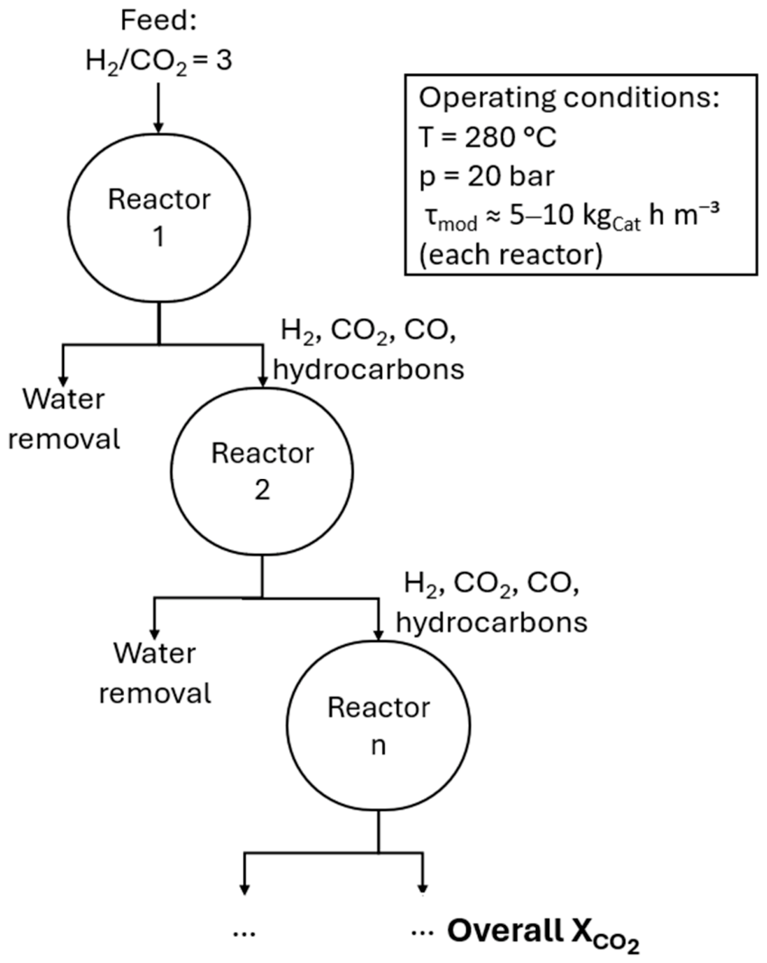
The effective kinetic model of the FeCuZnK coarse catalyst was subsequently applied in a multi-reactor concept to evaluate the effect of staged reactor operation on the achievable CO2 conversion. The process configuration considered in this study is shown schematically in Figure 2.
The process configuration consists of a series of fixed-bed reactor stages operated at constant temperature and pressure. The feed to the first reactor was H2/CO2 = 3, and the outlet stream of each stage was subjected to interstage water removal before entering the subsequent reactor. The remaining components, i.e., H2, CO2, CO, and hydrocarbons, were passed to the next stage. This procedure was introduced to reduce both the thermodynamic limitation of the RWGS reaction and the kinetic inhibition caused by H2O. The simulations of the multi-reactor concept were carried out at 280 °C and 20 bar with a modified residence time of 5 to 10 kgcat h m−3 per reactor stage. The overall CO2 conversion was calculated from the cumulative conversion over all reactor stages. In addition, the influence of the residence time per reactor stage was analyzed to assess its impact on the attainable overall CO2 conversion and the benefit of staged water removal.

2.3. Data Availability and Reproducibility

All equations, model parameters, and simulation settings required to reproduce the intrinsic and effective model calculations are provided in the manuscript and the Supporting Information. Additional simulation results generated in this work are available from the authors upon reasonable request and are provided in the Supporting Information.
No generative artificial intelligence was used to generate experimental data, perform simulations, or derive scientific conclusions in this study. If AI-based tools were used at all, they were limited to linguistic revision of the manuscript without influencing the scientific content.

3. Results

3.1. Intrinsic Reaction Modeling

3.1.1. Validation of the Intrinsic Kinetic Model

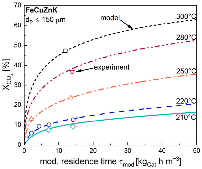
Figure 3 compares the experimentally determined CO2 conversions with the predictions of the intrinsic kinetic model for reaction temperatures between 210 and 300 °C. The model accurately reproduces the experimentally observed increase in CO2 conversion with increasing modified residence time over the investigated temperature range. At all temperatures, CO2 conversion rises rapidly at short residence times before gradually approaching a plateau at longer contact times.
For 210, 220 and 250 °C, several experimental data points are available over a broad residence time range, allowing a detailed validation of the intrinsic LHHW-model. The calculated conversion curves closely follow the experimental data, demonstrating that the model successfully captures both the initial kinetically controlled regime and the gradual decrease in conversion rate at increasing residence times. At 280 and 300 °C only single experimental points are available; nevertheless, these agree well with the predicted trends, supporting the applicability of the kinetic model over the investigated temperature range.
As expected, increasing the reaction temperature significantly enhances the intrinsic reaction rates and therefore shifts the conversion curves towards higher CO2 conversions. However, the diminishing slope of all curves at longer residence times indicates that progressively larger catalyst inventories or reactor volumes would be required to obtain only moderate additional conversion. This behavior already suggests that process intensification should primarily rely on optimized reactor concepts rather than simply increasing residence time.

3.1.2. Influence of the RWGS Activity

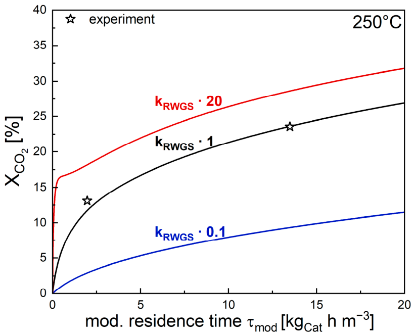
To further investigate the reaction network and the impact of different kinetic parameters, the intrinsic RWGS rate constant kRWGS was initially systematically varied while maintaining the Fischer–Tropsch kinetics unchanged. The investigated scaling factors of 0.1, 1 and 20 represent a strongly reduced (0.1), the experimentally determined (1) and a significantly increased RWGS activity (20), respectively.
As illustrated in Figure 4, decreasing the RWGS activity markedly by a factor of 10 (compared to the actual investigated catalyst) lowers the attainable CO2 conversion over the entire residence time range, confirming the central role of the RWGS reaction as the activation step for CO2 hydrogenation.
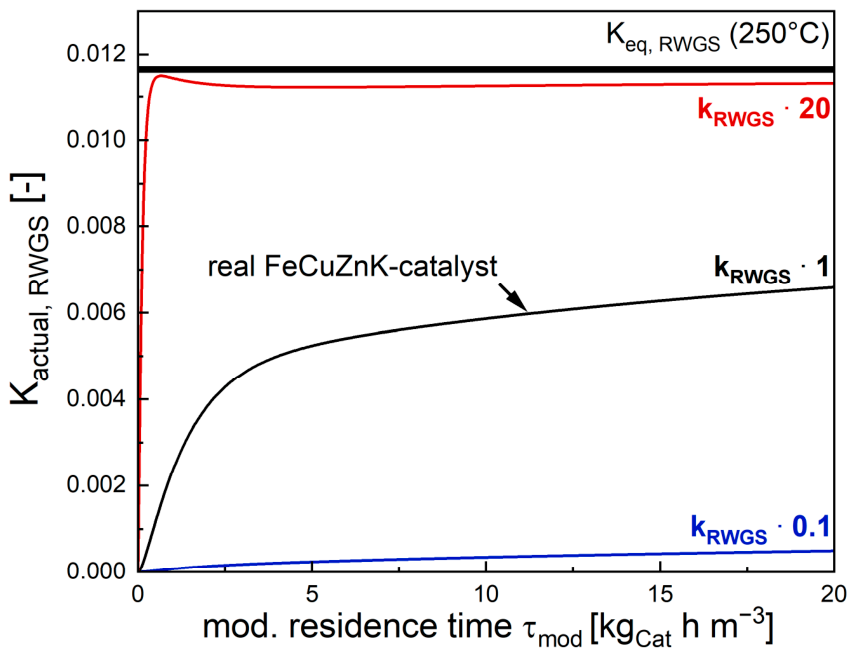
Conversely, increasing the intrinsic RWGS activity (kRWGS) by a factor of 20 (compared to the investigated catalyst) results in a consistently higher CO2 conversion, very pronounced in the front part of a fixed-bed reactor, i.e., for a very low residence time τmod below 1 kgcat h m−3. However, thereafter the improvement remains moderate despite the twenty-fold increase in kRWGS, suggesting that factors other than intrinsic kinetics increasingly govern the attainable conversion. To clarify this behavior, the calculated approach towards the thermodynamic equilibrium of the RWGS reaction, i.e., the influence of the residence time on the actual value of the reaction quotient of RWGS (Kactual,RWGS = pCO pH2O/(pCO2 pH2) is shown in comparison to the equilibrium constant (Keq,RWGS), calculated by Equation (3) for 250 °C, as shown in Figure 5.
Figure 5 demonstrates that increasing the RWGS rate constant primarily accelerates the approach to thermodynamic equilibrium rather than continuously increasing the attainable CO2 conversion. For the highest RWGS activity (kRWGS  20), the equilibrium is reached almost immediately after entering the reactor, whereas the actual reference catalyst approaches equilibrium only gradually with increasing residence time. Consequently, a further increase in intrinsic RWGS activity cannot substantially enhance the overall CO2 conversion because the reaction rapidly becomes thermodynamically limited instead of kinetically controlled, as also discussed for the indirect RWGS–FTS pathway by Featherstone and van Steen [27]. Additional simulations at 280 and 300 °C showed qualitatively similar behavior, indicating that this limitation persists within the investigated temperature range. Temperature and pressure may nevertheless influence the equilibrium position and therefore the benefit of increased RWGS activity; however, these parameters were kept constant in the present sensitivity analysis to isolate the effect of kRWGS.
These results indicate that catalyst optimization by solely increasing RWGS activity has limited potential once equilibrium is approached. A combined optimization of RWGS activity, temperature, and pressure may offer further improvements, but was beyond the scope of the present study. Instead, the results suggest that further gains require either modified thermodynamic conditions or reduced inhibition by reaction products.

3.1.3. Influence of Water Inhibition

Besides the intrinsic RWGS activity, product inhibition represents another important factor limiting the attainable CO2 conversion. According to the fitted LHHW parameters summarized in Table 1, water exhibits the strongest inhibitory effect on both the RWGS and FTS. In contrast, the inhibition by CO is comparatively weak, particularly for the RWGS. Therefore, the main manuscript focuses on the influence of water inhibition, whereas complementary model calculations regarding CO inhibition are provided in the Supporting Information. To evaluate the significance of water inhibition, a theoretical sensitivity analysis was performed while keeping all other kinetic parameters unchanged.
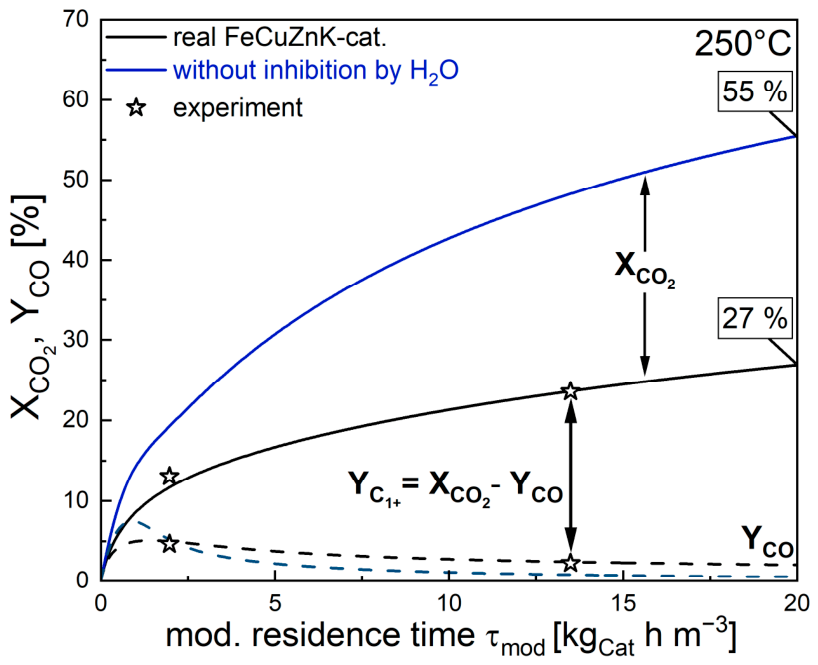
For this purpose, the H2O inhibition terms in both the RWGS and FTS rate expressions were set to zero (aH2O = 0 for both RWGS and FTS), representing a hypothetical catalyst that is completely insensitive to steam while otherwise retaining the same intrinsic catalytic activity. As shown in Figure 6, “eliminating” water inhibition considerably increases the attainable CO2 conversion over the complete residence time range. At a modified residence time of approximately 20 kgcat h m−3, the predicted CO2 conversion increases from approximately 27% for the real catalyst to about 55% for the hypothetical catalyst without steam inhibition. The effect becomes increasingly pronounced with increasing residence time as water continuously accumulates within the reactor.
The calculated CO yield initially increases in the absence of water inhibition but subsequently decreases below the level of the real catalyst at longer residence times. This behavior suggests that the elimination of steam inhibition affects not only the RWGS reaction but also the subsequent FTS and therefore changes the interaction between both reactions.
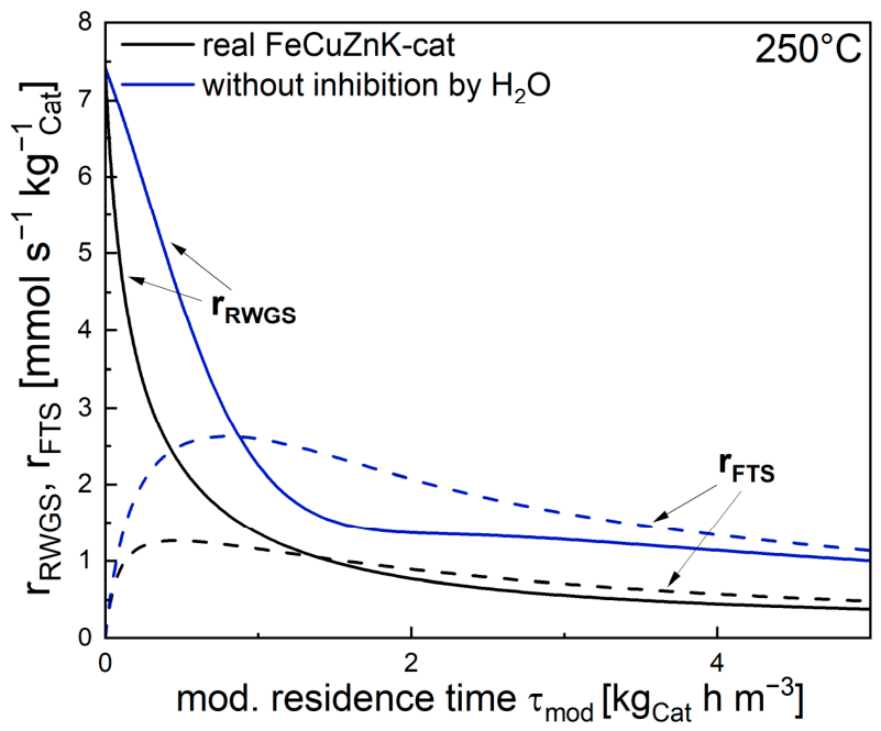
To explain the origin of this behavior, the calculated intrinsic reaction rates of both elementary reactions are compared in Figure 7. Without water inhibition, both the RWGS and FTS rate are significantly enhanced throughout the reactor. Near the reactor inlet, the RWGS reaction dominates due to the high CO2 concentration and exhibits the largest increase in activity. Consequently, substantially larger amounts of CO are initially formed. As residence time increases, however, the Fischer–Tropsch reaction also proceeds at considerably higher rates and increasingly consumes the additional CO produced by RWGS.
The combination of accelerated RWGS and accelerated FTS therefore explains the behavior observed in Figure 6. At short residence times, the faster RWGS reaction dominates and leads to higher CO formation. At longer residence times, the enhanced Fischer–Tropsch reaction converts the intermediate CO more rapidly into hydrocarbons, resulting in decreasing CO concentrations despite the overall increase in catalytic activity. The simulations shown in Figure 6 and Figure 7 clearly identify water as the dominant inhibiting species within the investigated reaction network. A pronounced inhibition of the reaction rate by in situ formed water during CO2 hydrogenation over an iron-based catalyst has also recently been reported by Featherstone and van Steen [28]. The strong influence of steam originates from its continuous formation by both the RWGS and Fischer–Tropsch reactions, leading to steadily increasing H2O concentrations along the reactor.
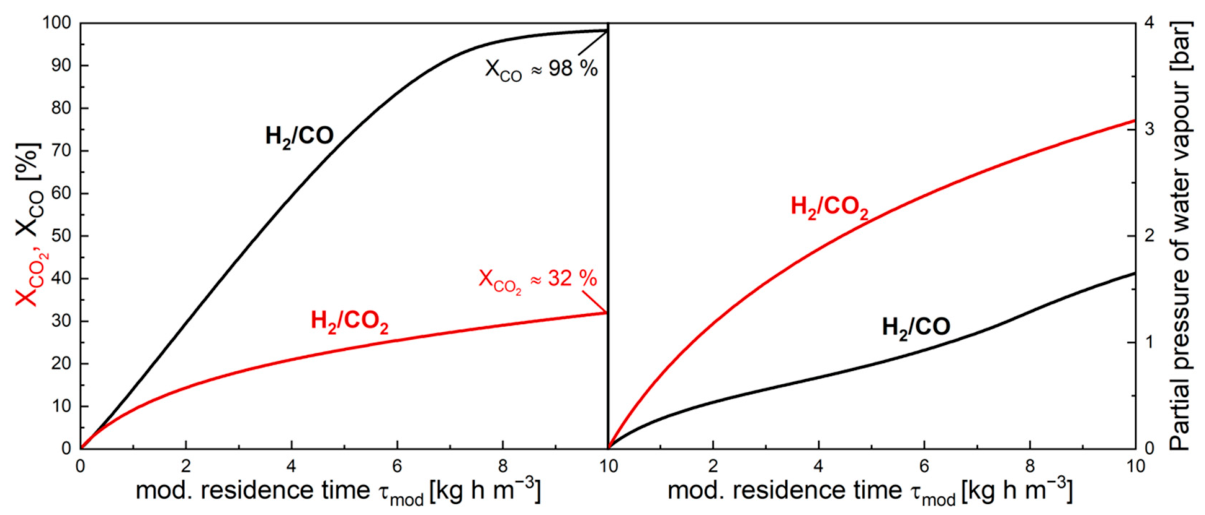
To further investigate this hypothesis, the intrinsic model was subsequently applied to both H2/CO and H2/CO2 feed compositions under otherwise identical operating conditions. This comparison allows the influence of steam accumulation to be separated from the effects associated with the different carbon sources. Figure 8 compares the behavior of the original FeCuZnK catalyst for both feed compositions while retaining the experimentally determined H2O inhibition parameters.
The left-hand side of Figure 8 reveals substantial differences between both operating modes despite the identical catalyst and reaction temperature. Under H2/CO conditions, almost complete CO conversion is achieved already at moderate residence times, reaching approximately 98% at a value of 10 kgcat h m−3. In contrast, the corresponding CO2 conversion during H2/CO2 operation reaches only approximately 32% under identical conditions.
The origin of this discrepancy becomes apparent when considering the corresponding steam partial pressures shown on the right-hand side of Figure 8. During CO2 hydrogenation, water is continuously generated by both the RWGS and FTS, leading to a strong accumulation of steam within the reactor and resulting in H2O partial pressures approaching approximately 3 bar at τmod = 10 kgcat h m−3. In contrast, substantially lower steam partial pressures are observed during CO hydrogenation, where only the Fischer–Tropsch reaction contributes to water formation and steam partial pressures remain below approximately 1.6 bar over the investigated residence time range.
The significantly higher steam concentration during CO2 hydrogenation therefore provides strong evidence that the lower CO2 conversion is primarily caused by the stronger inhibition of the coupled RWGS–FTS reaction network by water. To isolate the contribution of steam inhibition from all remaining kinetic effects, the H2O inhibition terms were subsequently “removed” while retaining the CO inhibition terms unchanged.
Figure 9 shows the corresponding comparison for the hypothetical catalyst without water inhibition.
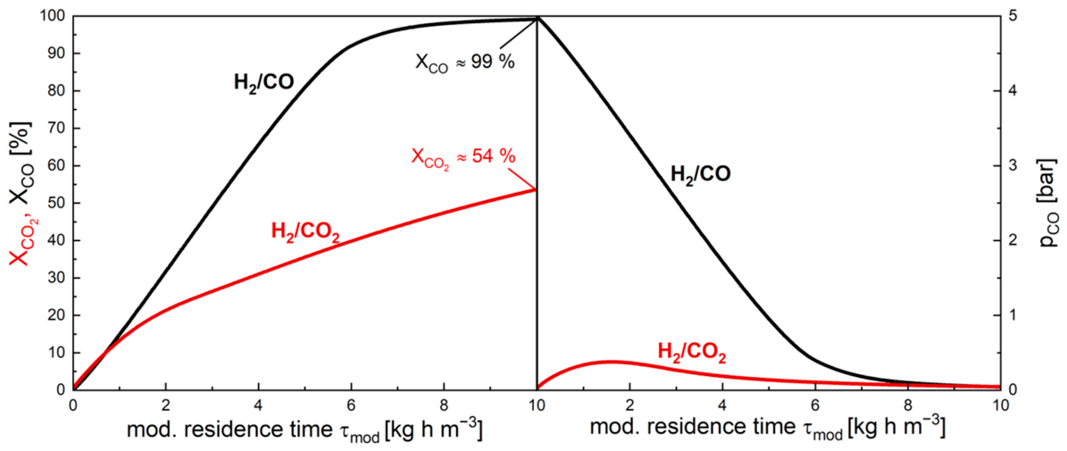
As shown on the left-hand side of Figure 9, eliminating water inhibition results in a substantial increase in the attainable CO2 conversion, which rises from approximately 32% to approximately 54% at τmod = 10 kgcat h m−3. In contrast, the CO conversion during H2/CO operation remains almost unaffected and still approaches complete conversion of approximately 99%.
Since water inhibition was intentionally “removed” in this theoretical analysis, the corresponding CO partial pressures are shown on the right-hand side of Figure 9 to evaluate the potential contribution of CO inhibition. During H2/CO operation, the initial CO partial pressure of approximately 5 bar decreases continuously as CO is consumed by FTS and approaches nearly zero at high residence times. In contrast, CO2 hydrogenation initially generates CO as an intermediate via the RWGS reaction, resulting in a gradual increase in CO partial pressure and a maximum value of approximately 0.4 bar at τmod = 1.5 kgcat h m−3. At longer residence times, the CO partial pressure decreases again as the Fischer–Tropsch reaction increasingly consumes the intermediate CO.
The large difference between the steam and CO partial pressures explains why water inhibition dominates the reactor behavior despite the explicit inclusion of CO inhibition in the LHHW model. Even under conditions without water inhibition, the CO partial pressure during CO2 hydrogenation remains comparatively low and therefore cannot exert an inhibitory effect comparable to that of steam.
Taken together, the intrinsic simulations identify water accumulation and thus inhibition as the dominant limitation of CO2 hydrogenation over the FeCuZnK catalyst. While moderate improvements may be achieved by increasing RWGS activity, the model calculations clearly demonstrate that reducing the steam concentration offers substantially greater potential for enhancing CO2 conversion than further optimization of the intrinsic catalyst kinetics. Iron-based FTS catalysts are—to our best knowledge—in general strongly sensitive to steam inhibition, and it is difficult to conceive that one will succeed in developing a superior catalyst in this respect.
From a process engineering perspective, these findings suggest that reactor design and reaction management may become more important than additional improvements in intrinsic catalytic activity once the RWGS kinetics and thermodynamic limitations have been largely optimized. In particular, the results indicate that the targeted removal of water during reaction could represent an effective strategy to suppress product inhibition and shift the coupled RWGS–FTS reaction network towards higher overall CO2 conversions.
Therefore, the following section extends the intrinsic kinetic model to coarse catalyst particles by incorporating intraparticle diffusion effects using reaction-specific effectiveness factors derived from the Thiele modulus approach. Based on this effective model, the potential of staged reactor operation with intermediate water removal is subsequently investigated using a multi-reactor cascade concept.

3.2. Effective Reaction Modeling

3.2.1. Validation of the Effective Model

The intrinsic kinetic model developed in Section 3.1 demonstrated that water accumulation represents the dominant limitation of CO2 hydrogenation over FeCuZnK. However, industrial Fischer–Tropsch catalysts are typically applied as millimeter-sized pellets rather than as fine catalyst powders, resulting in additional intraparticle mass transport limitations. To account for these effects, the intrinsic LHHW model was extended by incorporating reaction-specific effectiveness factors derived from the Thiele modulus approach described in Section 2.2.
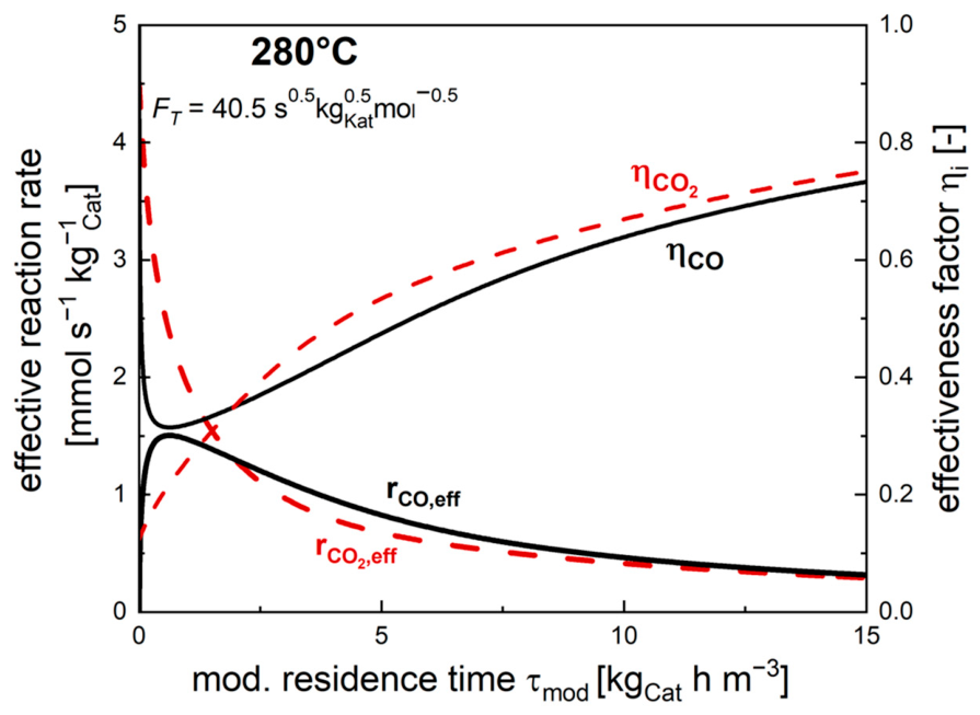
Figure 10 illustrates the resulting effectiveness factors and effective reaction rates for both reactions exemplarily at 280 °C.
At the reactor inlet, pronounced differences between both effectiveness factors are observed. The effectiveness factor of the RWGS reaction initially reaches only approximately 0.12 due to the high intrinsic CO2 reaction rate and the resulting strong intraparticle concentration gradients. In contrast, the effectiveness factor of the Fischer–Tropsch reaction is initially close to unity because CO is not present in the feed and therefore only negligible diffusion limitations occur for the initially low CO reaction rates.As residence time increases, the intrinsic RWGS reaction rate decreases due to both CO2 depletion and increasing inhibition by steam, resulting in a continuous increase in the corresponding effectiveness factor. Simultaneously, the formation of CO via RWGS causes the Fischer–Tropsch reaction rate to increase initially, leading to stronger diffusion limitations and a temporary decrease in the effectiveness factor of the FTS reaction. At longer residence times, however, the CO concentration decreases again as FTS increasingly consumes the intermediate CO, causing the effectiveness factor to recover and gradually approach that of the RWGS reaction.
The effective reaction rates reflect this behavior. The effective CO2 consumption rate reaches its maximum directly at the reactor inlet and subsequently decreases continuously along the reactor. In contrast, the effective CO consumption rate initially increases, reaches a maximum at approximately τmod = 0.5 kgcat h m−3, and decreases afterwards. Interestingly, the maximum CO reaction rate coincides with the minimum effectiveness factor of the FTS reaction, indicating that diffusion limitations are most pronounced in this region.
At long residence times, both effectiveness factors converge towards similar values of 0.7 to 0.75 due to the gradual convergence of the intrinsic RWGS and FTS reaction rates. These results clearly demonstrate that a realistic description of the effective kinetics requires separate effectiveness factors for both reactions rather than a single global pore utilization factor.
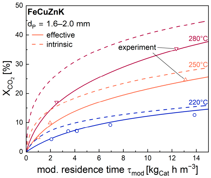
To evaluate the predictive capability of this approach, the effective model was subsequently compared with experimental conversion data obtained using coarse catalyst particles. Figure 11 demonstrates an excellent agreement between the effective model and the experimentally determined CO2 conversions over the investigated temperature range. In particular, the model accurately reproduces both the low-conversion region at short residence times and the gradual increase in conversion at longer contact times.
The comparison between intrinsic and effective modeling highlights the significance of intraparticle diffusion limitations for technical catalyst particles. For all temperatures, the intrinsic model systematically overestimates the attainable CO2 conversion because internal diffusion resistances are neglected. The deviation becomes increasingly pronounced with increasing temperature due to the higher intrinsic reaction rates and the resulting stronger concentration gradients within the catalyst particle.
The introduction of residence-time-dependent and reaction-specific effectiveness factors substantially reduces this discrepancy and allows the experimentally observed behavior of the coarse catalyst particles to be reproduced with high accuracy. The results therefore confirm that the explicit consideration of intraparticle diffusion effects represents a necessary extension of the intrinsic kinetic model for reactor-scale applications.
The validated effective model therefore provides the basis for investigating process concepts beyond catalyst-scale optimization. Since the intrinsic simulations identified steam accumulation as the dominant limitation of CO2 hydrogenation, the following section evaluates whether intermediate water removal in a staged reactor configuration can significantly enhance the attainable overall CO2 conversion.

3.2.2. Multi-Reactor Concept with Intermediate Water Removal

Following the successful validation of the effective model, the approach was subsequently applied to reactor-scale process optimization studies. In particular, the model was used to investigate the influence of reactor staging and intermediate water removal on the attainable overall CO2 conversion.
Industrial Fischer–Tropsch fixed-bed reactors are typically operated as cooled multitubular reactors, where significant radial and axial temperature gradients may occur due to the strongly exothermic reaction and heat-transfer limitations [29,30]. In the present work, however, an isothermal reactor operation was assumed for the sake of simplicity by representing the process as a series of ideal isothermal fixed-bed reactors. This assumption neglects local temperature variations arising from the RWGS and FTS reactions and therefore does not capture the resulting spatial changes in reaction rates, equilibrium, and inhibition. The calculated conversions should consequently be interpreted as an idealized assessment of the effect of interstage water removal rather than as a direct prediction of the performance of a specific industrial reactor. Between consecutive reactor stages, the product stream was cooled and the formed water was completely removed before entering the subsequent reactor stage. (The remaining very low partial pressure of water after cooling—e.g., to 20 °C—was neglected.)
This reactor concept directly addresses the dominant kinetic limitation identified in the previous sections, namely the inhibitory effect of water on both RWGS and FTS. By removing steam between reactor stages, the inhibition of the subsequent reactor is substantially reduced, thereby restoring higher effective reaction rates. Staged Fischer–Tropsch reactor concepts with intermediate product and water removal have previously been investigated as a strategy for achieving high overall conversion [31].
The simulations presented in this section are exclusively based on the validated effective model of the coarse FeCuZnK catalyst particles (dp = 1.6–2.0 mm) and do not represent experimental measurements. The following assumptions were applied throughout the calculations:
  • five identical isothermal fixed-bed reactors connected in series;
  • FeCuZnK coarse catalyst particles in each reactor stage;
  • initial feed composition of H2/CO2 = 3;
  • complete removal of water between reactor stages;
  • hydrocarbons were not considered as additional inhibiting species.
The concentrations entering each subsequent reactor stage were calculated from the outlet composition of the previous reactor after water removal.
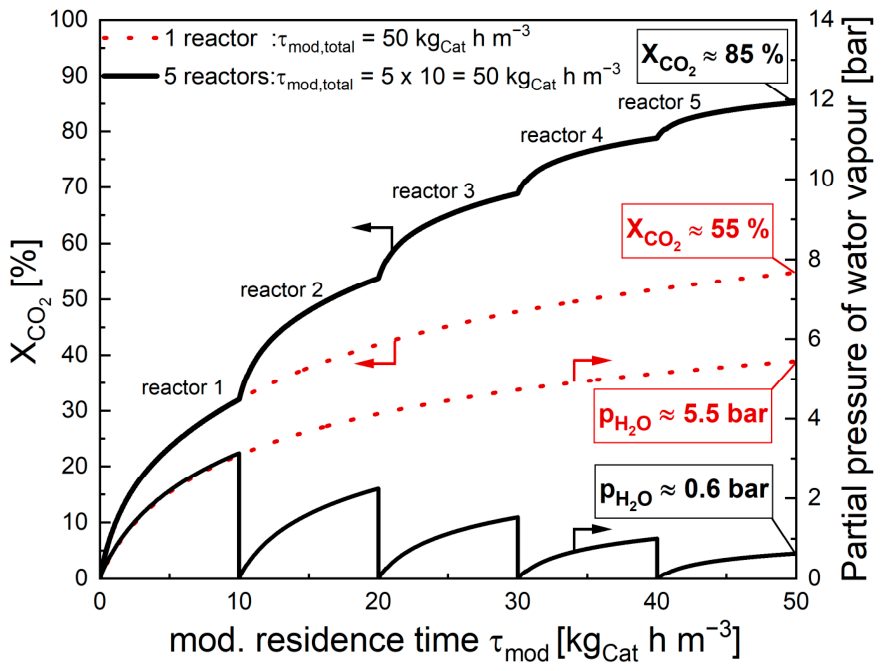
The first step was to compare the performance of a conventional single-reactor system with a five-stage reactor cascade with intermediate water removal (see Figure 12). The overall residence and thus the overall size and thus amount of catalyst, respectively, of each system (single reactor or five reactors in series) was kept constant.
As expected, both reactor concepts exhibit identical behavior within the first reactor stage since no water removal has yet occurred. Consequently, both the CO2 conversion and the steam partial pressure are identical up to a residence time of 10 kgcat h m−3.
However, immediately after the first intermediate water removal step, substantial differences between both reactor concepts become apparent. At the end of the second reactor stage, corresponding to a cumulative residence time of 20 kgcat h m−3, the reactor cascade already reaches a CO2 conversion of 54%, whereas the corresponding single-reactor configuration achieves only 42% under identical operating conditions.
The advantage of staged operation becomes even more pronounced at longer residence times. While the conventional reactor reaches only 55% CO2 conversion after a cumulative residence time of 50 kgcat h m−3, the five-stage cascade achieves an overall conversion of 85%. Interestingly, the conversion level obtained in the single-reactor configuration after 50 kgcat h m−3 is already reached after only two reactor stages in the cascade configuration.
Similar calculations were also done for even more stages, even though this is unrealistic in an industrial setting: For 10 stages (τmod = 5 kgcat h m−3 per reactor), the final CO2 conversion would then be 92%, and for the theoretical boarder case of an infinite number of stages (hence an instantaneous and complete removal of all water/steam formed by RWGS and FTS) the final conversion reached after a total residence time of 50 kgcat h m−3 would be even 95%.
The corresponding water vapour partial pressures strongly support this interpretation. In the single-reactor configuration, steam continuously accumulates and reaches 5.5 bar at the reactor outlet. In contrast, the repeated removal of water maintains substantially lower local steam concentrations within each reactor stage.
These results clearly demonstrate that intermediate water removal represents a highly effective strategy for increasing the attainable CO2 conversion and that process design can provide significantly larger improvements than catalyst optimization alone once the intrinsic kinetics have been optimized. To further investigate the interaction between reactor staging and local steam accumulation, the influence of the residence time per reactor stage, i.e., before water is removed, was subsequently analyzed (see Figure 13).
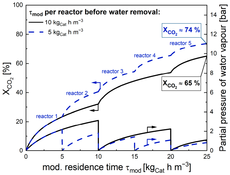
Reducing the residence time per reactor stage while maintaining intermediate water removal results in a further improvement of the reactor performance at equal cumulative residence times. The reactor cascade operated with τmod = 5 kgcat h m−3 per reactor already reaches approximately 74% CO2 conversion after a cumulative residence time of only 25 kgcat h m−3. Under identical overall residence time conditions, the configuration with τmod = 10 kgcat h m−3 per reactor (i.e., only two times an interstage water removal and thus formally 2.5 stages) achieves only approximately 65% conversion.
It should be noted that the multi-reactor simulations represent an idealized isothermal reactor configuration. In practical fixed-bed FTS reactors, axial and radial temperature gradients may occur due to the exothermic nature of the reactions and heat-transfer limitations. Such temperature variations would locally affect the RWGS and FTS rates, the RWGS equilibrium, and the strength of product inhibition and could therefore alter the absolute CO2 conversion predicted for a real reactor. Nevertheless, the modeled trend of improved conversion through intermediate water removal is expected to remain relevant, as the underlying mechanism is the reduction of H2O inhibition. A detailed assessment of these effects would require a coupled mass and energy balance for non-isothermal reactor operation and is beyond the scope of the present study.
The superior performance of smaller individual reactor stages originates from the lower steam concentrations that develop within each reactor. Since water accumulation is interrupted more frequently, the inhibitory effect acts over shorter reactor lengths and therefore limits the reaction to a smaller extent. This behavior is also reflected by the lower maximum steam partial pressures observed for the shorter reactor stages.
Nevertheless, shorter residence times per reactor stage require a larger number of reactors to achieve very high overall conversions. Consequently, a clear process engineering trade-off emerges between reactor performance and plant complexity. Increasing the number of reactor stages improves conversion through more frequent water removal but simultaneously increases capital costs and process complexity. Conversely, larger reactor volumes reduce the number of required process units but suffer from stronger steam inhibition and therefore lower overall conversion efficiencies.
Overall, the results demonstrate that high CO2 conversions in CO2-based Fischer–Tropsch synthesis can only be achieved by simultaneously considering intrinsic kinetics, intraparticle diffusion and reactor design. The validated effective model therefore provides not only an improved description of catalyst behavior but also a powerful tool for the quantitative evaluation and optimization of industrial reactor concepts.

4. Conclusions

The present work provides mechanistic insights into the intrinsic and effective kinetics of CO2 hydrogenation over a potassium-promoted FeCuZnK Fischer–Tropsch catalyst. The intrinsic LHHW-model successfully reproduced the experimentally observed conversion behavior and revealed that increasing the RWGS activity only moderately improves the attainable CO2 conversion because the reaction rapidly approaches thermodynamic equilibrium.
The model calculations identified water as the dominant inhibiting species within the coupled RWGS–FTS reaction network, whereas the influence of CO inhibition remained comparatively small. The significantly higher steam partial pressures during CO2 hydrogenation compared to CO hydrogenation explain a large part of the limited CO2 conversion typically observed in CO2-based Fischer–Tropsch synthesis.
By introducing reaction-specific effectiveness factors based on the Thiele modulus approach, the intrinsic model was successfully extended to technical catalyst particles. The effective model accurately reproduced the experimentally observed behavior of coarse FeCuZnK catalyst particles and demonstrated the importance of considering residence-time-dependent intraparticle diffusion limitations for both RWGS and FTS.
Finally, the validated effective model was applied to reactor-scale optimization studies. Multi-reactor cascade concepts with intermediate water removal significantly outperformed conventional single-reactor operation. A five-stage reactor cascade increased the attainable CO2 conversion from approximately 55% to about 85% under otherwise identical operating conditions, highlighting the strong influence of local steam concentrations on catalyst performance. The multi-reactor simulations assume idealized isothermal reactor stages; therefore, the reported absolute conversions should not be interpreted as direct predictions for industrial non-isothermal FTS reactors. A coupled mass and energy balance would be required to quantify the impact of temperature gradients on the reactor performance.
Overall, the results demonstrate that high CO2 conversions in CO2-based FTS can only be achieved by an integrated consideration of intrinsic kinetics, diffusion phenomena, and reactor design. It should be noted that the lumped FTS description does not resolve the detailed hydrocarbon product distribution; consequently, the predicted CO2 conversion cannot be directly interpreted in terms of C5+ or liquid hydrocarbon yield. The developed modeling framework therefore provides a valuable tool for the design and optimization of reactor concepts for CO2 hydrogenation to hydrocarbons based on renewable hydrogen and carbon dioxide.

Supplementary Materials

The following supporting information can be downloaded at: https://www.mdpi.com/article/10.3390/c12030070/s1, Figure S1. Schematic preparation procedure for the granulated FeCuZnK catalyst, including mixing, drying, crushing, sieving, thermal treatment, granulation, and final calcination; Figure S2. Modeled CO2 conversion and CO yield as a function of modified residence time for the original FeCuZnK catalyst and the hypothetical case without CO inhibition at 250 °C, 20 bar, and H2/CO2 = 3. The parameters c1,CO and c2,CO were set to zero, while all other kinetic parameters were kept unchanged; Figure S3. Calculated intrinsic RWGS and FTS reaction rates as a function of modified residence time for the original FeCuZnK catalyst and the hypothetical case without CO inhibition. Simulations were performed at 250 °C and 20 bar using a H2/CO2 feed ratio of 3 and the intrinsic kinetic model.

Author Contributions

Conceptualization, F.M. and A.J.; methodology, F.M.; software, F.M.; validation, F.M.; formal analysis, F.M.; investigation, F.M.; resources, A.J.; data curation, F.M.; writing—original draft preparation, F.M.; writing—review and editing, F.M. and A.J.; visualization, F.M.; supervision, A.J.; project administration, A.J.; funding acquisition, A.J. All authors have read and agreed to the published version of the manuscript.

Funding

This research received no external funding.

Data Availability Statement

The data supporting the findings of this study are available from the corresponding author upon reasonable request.

Acknowledgments

During the preparation of this manuscript, the author used ChatGPT (OpenAI, GPT-5.5) for language editing, text refinement, and improvement of the manuscript structure. The authors reviewed and edited all generated content and take full responsibility for the content of this publication.

Conflicts of Interest

The authors declare no conflicts of interest.

Abbreviations

The following abbreviations are used in this manuscript:
BETBrunauer–Emmett–Teller
DMDirect Methanation
FTSFischer–Tropsch Synthesis
RWGSReverse Water–Gas Shift
WGSWater–Gas Shift
LHHWLangmuir–Hinshelwood–Hougen–Watson
HCsHydrocarbons

Nomenclature

SymbolDescriptionUnit
an,H2O, bn,CO2, cn,COInhibition parameterm3 mol−1
c i , f l Concentration of component i in the liquid phasemol m−3
c i , g Concentration of component i in the gas phasemol m−3
d P Particle diameterm
D e f f Effective diffusion coefficientm2 s−1
D i , W a x Diffusion coefficient of component i in waxm2 s−1
E A Activation energyJ mol−1
E D , i Activation energy for diffusionJ mol−1
FTTemperature-dependent fitting parameters0.5 kgCat0.5 mol−0.5
H i Henry coefficientPa m3 mol−1
k i Rate constant for reaction im6 mol−1 s−1 kgCat−1
k 0 , i Pre-exponential factor of reaction im6 mol−1 s−1 kgCat−1
K e q , R W G S Equilibrium constant of RWGS-
K a c t u a l , R W G S Reaction quotient of RWGS = pCO pH2O/(pCO2 pH2)-
p i Partial pressure of component iPa
r i Reaction rate of component imol kgCat−1 s−1
r e f f Effective reaction ratemol kgCat−1 s−1
r i n t Intrinsic reaction ratemol kgCat−1 s−1
R Universal gas constant (8.314)J mol−1 K−1
T Temperature°C/K
Y C O Yield of CO-
X C O 2 Conversion of CO2-
ε P Particle porosity-
η Pore utilization factor-
ρ P Particle densitykg m−3
τ Tortuosity-
τ m o d Modified residence timekgCat s m−3
ϕ Thiele modulus-

References

  1. Marinho, A.L.; Panzone, C.; Chidraoui, A.M.; Roussey, A.; Chappaz, A.; Chatelier, C.; Vachaud, J.; Faucheux, V. State-of-the-art direct CO2 hydrogenation to liquid hydrocarbons: Analysis of Fischer–Tropsch and methanol-mediated routes. J. CO2 Util. 2025, 101, 103189. [Google Scholar] [CrossRef] [Scilit]
  2. Daza, Y.A.; Kuhn, J.N. CO2 conversion by reverse water gas shift catalysis: Comparison of catalysts, mechanisms and their consequences for CO2 conversion to liquid fuels. RSC Adv. 2016, 6, 49675–49691. [Google Scholar] [CrossRef] [Scilit]
  3. Landau, M.V.; Meiri, N.; Utsis, N.; Vidruk Nehemya, R.; Herskowitz, M. Conversion of CO2, CO, and H2 in CO2 Hydrogenation to Fungible Liquid Fuels on Fe-Based Catalysts. Ind. Eng. Chem. Res. 2017, 56, 13334–13355. [Google Scholar] [CrossRef] [Scilit]
  4. Gao, R.; Wang, L.; Zhang, L.; Zhang, C.; Jun, K.-W.; Ki Kim, S.; Park, H.-G.; Zhao, T.; Gao, Y.; Zhu, Y.; et al. Upcycling of CO2 into sustainable hydrocarbon fuels via the integration of Fe-based Fischer-Tropsch synthesis and olefin oligomerization: A comparative case study. Fuel 2022, 325, 124855. [Google Scholar] [CrossRef] [Scilit]
  5. Kaiser, P.; Unde, R.B.; Kern, C.; Jess, A. Production of Liquid Hydrocarbons with CO2 as Carbon Source based on Reverse Water-Gas Shift and Fischer-Tropsch Synthesis. Chem. Ing. Tech. 2013, 85, 489–499. [Google Scholar] [CrossRef] [Scilit]
  6. Bayer, T. R&D&I and Industry Examples: Ineratec’s ICO2CHEM Project to Utilize CO2. In CO2 and CO as Feedstock; Kircher, M., Schwarz, T., Eds.; Springer International Publishing: Cham, Switzerland, 2023; pp. 381–385. [Google Scholar]
  7. Han, Y.; Fang, C.; Ji, X.; Wei, J.; Ge, Q.; Sun, J. Interfacing with Carbonaceous Potassium Promoters Boosts Catalytic CO2 Hydrogenation of Iron. ACS Catal. 2020, 10, 12098–12108. [Google Scholar] [CrossRef] [Scilit]
  8. Han, J.; Liu, W.; Zhang, L.; Ren, H.; Wu, C.; Zhang, J.; Gong, C.; Yang, G.; Yang, H.; Zhang, S.; et al. Highly Efficient CO2 Hydrogenation to Linear α-Olefins on FeZnK Catalysts with Balanced Zn–O–Fe Interfaces and Fe5C2 Species. ACS Catal. 2025, 15, 3940–3954. [Google Scholar] [CrossRef] [Scilit]
  9. Panzone, C.; Philippe, R.; Nikitine, C.; Vanoye, L.; Bengaouer, A.; Chappaz, A.; Fongarland, P. Catalytic and Kinetic Study of the CO2 Hydrogenation Reaction over a Fe–K/Al2O3 Catalyst toward Liquid and Gaseous Hydrocarbon Production. Ind. Eng. Chem. Res. 2021, 60, 16635–16652. [Google Scholar] [CrossRef] [Scilit]
  10. Meng, W.; Rocks, R.; Dugulan, A.I.; Xie, J. Role of potassium on reaction pathways in CO2 hydrogenation: Insights from reverse water gas shift and Fischer-Tropsch synthesis over the carbon-supported iron-based catalysts. J. CO2 Util. 2026, 111, 103543. [Google Scholar] [CrossRef] [Scilit]
  11. Mai, F.; Jess, A. CO2 Conversion to Higher Hydrocarbons on Iron-Based Catalysts: Promoter Impact and Kinetic Studies. Chem. Eng. Technol. 2025, 48, e12010. [Google Scholar] [CrossRef] [Scilit]
  12. Mai, F. CO2-Basierte Fischer-Tropsch-Synthese an Promotierten Eisensinterkatalysatoren zur Erzeugung Höherer Kohlenwasserstoffe aus Regenerativem Wasserstoff und CO2. Ph.D. Thesis, University Bayreuth, Bayreuth, Germany, 2026. Submitted/Publication expected end of 2026. [Google Scholar]
  13. Capo Pérez, C.; Blanco, E. Production of hydrocarbon from CO2-FT reaction over Fe-based catalysts: Effect of the promoter and bimetallic Fe-Metal carbide. Appl. Catal. A Gen. 2025, 705, 120459. [Google Scholar] [CrossRef] [Scilit]
  14. Satthawong, R.; Koizumi, N.; Song, C.; Prasassarakich, P. Comparative Study on CO2 Hydrogenation to Higher Hydrocarbons over Fe-Based Bimetallic Catalysts. Top. Catal. 2014, 57, 588–594. [Google Scholar] [CrossRef] [Scilit]
  15. Rodemerck, U.; Holeňa, M.; Wagner, E.; Smejkal, Q.; Barkschat, A.; Baerns, M. Catalyst Development for CO2 Hydrogenation to Fuels. ChemCatChem 2013, 5, 1948–1955. [Google Scholar] [CrossRef] [Scilit]
  16. Riedel, T.; Schaub, G.; Jun, K.-W.; Lee, K.-W. Kinetics of CO2 Hydrogenation on a K-Promoted Fe Catalyst. Ind. Eng. Chem. Res. 2001, 40, 1355–1363. [Google Scholar] [CrossRef] [Scilit]
  17. Moe, J.M. Design of water-gas shift reactors. Chem. Eng. Prog. 1961, 58, 33–36. [Google Scholar]
  18. Zimmerman, W.H.; Bukur, D.B. Reaction kinetics over iron catalysts used for the fischer-tropsch synthesis. Can. J. Chem. Eng. 1990, 68, 292–301. [Google Scholar] [CrossRef] [Scilit]
  19. Anderson, R.B. Catalysts for the Fischer-Tropsch Synthesis. In Catalysis; Reinhold Publishing Corporation: New York, NY, USA, 1956; pp. 29–255. [Google Scholar]
  20. Dry, M.E. Advances in Fishcher-Tropsch Chemistry. Prod. R&D 1976, 15, 282–286. [Google Scholar] [CrossRef] [Scilit]
  21. Iglesias, M.; Edzang, R.; Schaub, G. Combinations of CO/CO2 reactions with Fischer–Tropsch synthesis. Catal. Today 2013, 215, 194–200. [Google Scholar] [CrossRef] [Scilit]
  22. Saeidi, S.; Najari, S.; Fazlollahi, F.; Nikoo, M.K.; Sefidkon, F.; Klemeš, J.J.; Baxter, L.L. Mechanisms and kinetics of CO2 hydrogenation to value-added products: A detailed review on current status and future trends. Renew. Sustain. Energy Rev. 2017, 80, 1292–1311. [Google Scholar] [CrossRef] [Scilit]
  23. Graaf, G.H.; Sijtsema, P.; Stamhuis, E.J.; Joosten, G. Chemical equilibria in methanol synthesis. Chem. Eng. Sci. 1986, 41, 2883–2890. [Google Scholar] [CrossRef] [Scilit]
  24. Wang, Y.-N.; Xu, Y.-Y.; Xiang, H.-W.; Li, Y.-W.; Zhang, B.-J. Modeling of Catalyst Pellets for Fischer−Tropsch Synthesis. Ind. Eng. Chem. Res. 2001, 40, 4324–4335. [Google Scholar] [CrossRef] [Scilit]
  25. Chou, J.S.; Chao, K.C. Solubility of synthesis and product gases in a Fischer-Tropsch SASOL wax. Ind. Eng. Chem. Res. 1992, 31, 621–623. [Google Scholar] [CrossRef] [Scilit]
  26. Pöhlmann, F. Zusammenspiel von Chemischer Reaktion und Porendiffusion bei der Kobaltkatalysierten Fischer-Tropsch-Synthese Unter Einsatz von CO2-Haltigem Synthesegas. Ph.D. Thesis, University Bayreuth, Bayreuth, Germany, 2017. [Google Scholar]
  27. Featherstone, N.S.; van Steen, E. Meta-analysis of the thermo-catalytic hydrogenation of CO2. Catal. Today 2023, 423, 113951. [Google Scholar] [CrossRef] [Scilit]
  28. Featherstone, N.S.; van Steen, E. The effect of altering CO2-conversion on iron-based direct CO2-hydrogenation. Catal. Today 2025, 452, 115240. [Google Scholar] [CrossRef] [Scilit]
  29. Kern, C.; Jess, A. Pore Diffusion in the Fischer–Tropsch Synthesis: Limitation or Advantage in Multi-Tubular Reactors? Chem. Eng. Technol. 2025, 48, e70049. [Google Scholar] [CrossRef] [Scilit]
  30. Terziotti Neto, E.; Da Silva, L.A.; Bortolini, H.R.; Alves, R.M.B.; Giudici, R. Current Trends and Innovations in CO2 Hydrogenation Processes. Processes 2026, 14, 293. [Google Scholar] [CrossRef] [Scilit]
  31. van Steen, E.; Claeys, M.; Möller, K.P.; Nabaho, D. Comparing a cobalt-based catalyst with iron-based catalysts for the Fischer-Tropsch XTL-process operating at high conversion. Appl. Catal. A Gen. 2018, 549, 51–59. [Google Scholar] [CrossRef] [Scilit]
Figure 1. Schematic reaction network of CO2 hydrogenation over FeCuZnK. Hydrocarbons are formed via the RWGS–FTS pathway, i.e., CO2 is first converted to CO by reverse water–gas shift and CO is subsequently converted to hydrocarbons by Fischer–Tropsch synthesis. Direct CO2 methanation is suppressed for the K-promoted FeCuZnK catalyst and was therefore not considered in the kinetic model used in this work; for details see [11,12].
Carbon 12 00070 g001
Figure 2. Schematic representation of the multi-reactor concept used for effective reactor-scale modeling of CO2 hydrogenation over FeCuZnK. The feed to the first reactor consists of H2 and CO2 at a molar ratio of H2/CO2 = 3. Between successive reactor stages, H2O is selectively removed, while the remaining components (H2, CO2, CO, and hydrocarbons) are passed to the next reactor. The simulations were carried out at 280 °C and 20 bar with a modified residence time of 5 to 10 kgcat h m−3 per stage. The overall CO2 conversion results from the cumulative conversion over all reactor stages.
Carbon 12 00070 g002
Figure 3. Experimental validation of the intrinsic LHHW-model. CO2 conversion as a function of the modified residence time (τmod) at reaction temperatures of 210, 220, 250, 280 and 300 °C and a total pressure of 20 bar over the FeCuZnK fine-grain catalyst (dp < 150 µm). Symbols represent experimental data and lines the corresponding model predictions.
Carbon 12 00070 g003
Figure 4. Effect of varying the intrinsic RWGS rate constant on the calculated CO2 conversion as a function of the modified residence time at 250 °C (total pressure of 20 bar). The intrinsic Fischer–Tropsch kinetics remained unchanged, while the RWGS rate constant was multiplied by factors of 0.1, 1 (reference case of catalyst used in this work) and 20 to evaluate the sensitivity of the coupled reaction network.
Carbon 12 00070 g004
Figure 5. Calculated approach of the RWGS reaction towards thermodynamic equilibrium at 250 °C for different intrinsic RWGS activities (total pressure of 20 bar). The black horizontal line represents the thermodynamic equilibrium constant, while the colored curves correspond to RWGS rate constants scaled by factors of 0.1, 1 (actual investigated catalyst) and 20.
Carbon 12 00070 g005
Figure 6. Theoretical influence of water inhibition on the intrinsic reaction network at 250 °C and 20 bar for an H2/CO2 feed ratio of 3. Comparison between the original FeCuZnK (black) catalyst and a hypothetical catalyst without H2O inhibition (aH2O = 0 for both RWGS and FTS; blue). Solid lines represent CO2 conversion and dashed lines CO yield.
Carbon 12 00070 g006
Figure 7. Calculated intrinsic RWGS and FTS reaction rates as a function of residence time for the original FeCuZnK catalyst (black) and for the hypothetical case without water inhibition (blue). Solid lines represent RWGS rates and dashed lines FTS rates. Simulations were performed at 250 °C and 20 bar using a H2/CO2 feed ratio of 3 and the intrinsic kinetic model.
Carbon 12 00070 g007
Figure 8. Comparison of the modeled behavior of the intrinsic FeCuZnK catalyst during CO and CO2 hydrogenation at 250 °C and 20 bar using feed ratios of H2/CO = 3 and H2/CO2 = 3, respectively. (Left): CO conversion during H2/CO operation and CO2 conversion during H2/CO2 operation as a function of modified residence time. (Right): Corresponding partial pressure of water vapor formed during reaction. All results originate exclusively from model calculations.
Carbon 12 00070 g008
Figure 9. Comparison of the modeled behavior of the intrinsic FeCuZnK catalyst during CO and CO2 hydrogenation after removing H2O inhibition from the kinetic model (aH2O = 0 for both RWGS and FTS). Simulations were performed at 250 °C and 20 bar using feed ratios of H2/CO = 3 and H2/CO2 = 3. (Left): CO conversion during H2/CO operation and CO2 conversion during H2/CO2 operation as a function of modified residence time. (Right): Corresponding CO partial pressures within the reactor. All results are purely model-based and do not represent experimental measurements.
Carbon 12 00070 g009
Figure 10. Residence-time-dependent effectiveness factors ηi (dashed lines, right axis) and effective reaction rates (solid lines, left axis) for the RWGS and FTS reactions calculated for FeCuZnK coarse catalyst particles (dp = 1.6–2.0 mm) at 280 °C, 20 bar and H2/CO2 = 3. The transport-related scaling parameter obtained for this temperature was FT = 40.5 s0.5 kgcat0.5 m−0.5.
Carbon 12 00070 g010
Figure 11. Comparison of experimentally measured CO2 conversions with the predictions of the effective kinetic model for FeCuZnK coarse catalyst particles (dp = 1.6–2.0 mm) at 220, 250 and 280 °C and 20 bar using H2/CO2 = 3. Solid lines represent the effective model, symbols the experimental data and dashed lines the corresponding intrinsic model predictions.
Carbon 12 00070 g011
Figure 12. Comparison of the modeled overall CO2 conversion (left axis) and local water vapour partial pressure (right axis) as a function of cumulative modified residence time for a conventional single-reactor system (red dotted lines) and a five-stage reactor cascade with complete intermediate water removal (black solid lines). Each reactor stage of the cascade was operated at a constant modified residence time τmod of 10 kgcat h m−3. Simulations were performed at 280 °C, 20 bar and an initial feed ratio of H2/CO2 = 3 using the effective model of the FeCuZnK coarse catalyst (dp = 1.6–2.0 mm).
Carbon 12 00070 g012
Figure 13. Comparison of two reactor cascades with two different modified residence times per reactor stage before water is removed. The total residence time was kept constant (τmod,total = 25 kgcat h m−3). Solid black lines represent τmod = 10 kgcat h m−3 per reactor (2.5 stages), whereas dashed blue lines correspond to τmod = 5 kgcat h m−3 per reactor (i.e., 5 stages). The left axis shows the overall CO2 conversion and the right axis the local water vapour partial pressure as a function of cumulative modified residence time. Simulations were performed at 280 °C, 20 bar and H2/CO2 = 3 using the effective FeCuZnK coarse-particle model.
Carbon 12 00070 g013
Table 1. Kinetic parameters—see Equations (1) and (2)—of the intrinsic LHHW model for CO2 hydrogenation over the FeCuZnK catalyst [12].
RWGSFTS
EA ak0 b a 1 , H 2 O  c b 1 , C O 2  cc1,CO cEA ak0 b a 2 , H 2 O  c b 2 , C O 2  cc2,CO c
1044.91.190.060.2810125.20.640.051.25
Units: (a): kJ mol−1; (b): ∙104 m6 mol−1 s−1 kgCat−1; (c): m3 mol−1.
Table 2. Particle properties and transport parameters (240 °C) used for the effective modeling of the FeCuZnK coarse catalyst particles; in Equation (7) a mean value for dP of 1.8 mm was used.
dP [mm]ρP [g cm−3]εP [−]τP [−]Hi [103 Pa m3 mol−1]
[25]
Di,wax,0 [10−7 m2 s−1]
[26]
ED,i [kJ mol−1]
[26]
CO2COCO2COCO2CO
1.6–2.03.40.312.110213.55.613.414.9
Table 3. Temperature-dependent transport-related parameter FT used for the effective modeling of the FeCuZnK coarse catalyst particles; for comparison, the values based on Equation (7) are also listed.
Temperature
[°C]
FT
[s0.5 kgCat0.5 mol−0.5]
FT,CO, Equation (7)
[s0.5 kgCat0.5 mol−0.5]
FTCO2, Equation (7)
[s0.5 kgCat0.5 mol−0.5]
220487756
250456951
28040.56347
300406044
Disclaimer/Publisher’s Note: The statements, opinions and data contained in all publications are solely those of the individual author(s) and contributor(s) and not of MDPI and/or the editor(s). MDPI and/or the editor(s) disclaim responsibility for any injury to people or property resulting from any ideas, methods, instructions or products referred to in the content.