Article

Effect of Carbon Fixation Time on the Properties of Gangue–Fly Ash Composite Filling Materials: Carbon Fixation Amount and Rheological Properties

1
Yankuang Energy Group Company Limited, Zoucheng 273500, China
2
State Key Laboratory for Fine Exploration and Intelligent Development of Coal Resources, School of Mines, China University of Mining and Technology, Xuzhou 221116, China
*
Author to whom correspondence should be addressed.
C 2025, 11(3), 71; https://doi.org/10.3390/c11030071 (registering DOI)
Submission received: 2 August 2025 / Revised: 31 August 2025 / Accepted: 6 September 2025 / Published: 8 September 2025

Abstract

Coal-based solid wastes are used for carbon fixation, which can achieve the dual purpose of resource utilization of coal-based solid wastes and CO2 storage, but carbon fixation has a negative impact on the rheological properties of filling slurry. This paper explores the effect of carbon fixation time on the carbon fixation performance and rheological properties of coal gangue (CG)–fly ash (FA) composite filling materials (CFS) through rheometer, X-ray diffraction, Fourier transform infrared spectroscopy, scanning electron microscopy, and other testing methods. The results show that, with an increase in the carbon fixation time, the carbon fixation amount of the CFS shows a trend of increasing first and then stabilizing. Considering the carbon fixation amount and rheological properties of the CFS together, the optimal carbon fixation time is 2 h. At this time, the carbon fixation amount of the CFS is 1.18%, and the yield stress and plastic viscosity are 155.93 Pa and 0.17 Pa·s, respectively. However, with a further increase in the carbon fixation time, the carbon fixation amount basically tends to be stable, mainly because the calcium ions in the CFS are gradually consumed by the reaction as the carbon fixation time increases. The research results are of great significance for improving the utilization of coal-based solid waste and CO2 storage.

1. Introduction

A large amount of solid waste is discharged during the development and utilization of coal resources, mainly including CG and FA. The large amount of coal-based solid waste discharged and the low utilization rate pose the risks of resource waste and environmental pollution [1,2,3]. Globally, coal mining generates approximately 800 million tonnes of CG annually, representing 15% to 20% of the total coal output. Concurrently, annual FA production has surpassed 600 million tonnes [4,5]. At present, the amount of coal-based solid waste is large, and the discharge occupies a large area, which not only brings safety problems such as landslides but also causes a series of ecological and environmental problems such as air pollution and water environment damage [6,7,8]. At the same time, the development and utilization of coal also emit a large amount of CO2. In 2023, emissions from energy consumption reached 37.4 billion tons of CO2, an increase of 410 million tons compared to the previous year [9]. CO2 emissions can lead to global warming and trigger a series of environmental problems, such as melting glaciers, rising sea levels, and more extreme weather events [10,11,12]. Therefore, in the face of ecological and environmental pressure, how to safely, efficiently, and greenly dispose of bulk solid waste and mineralize and store CO2 are some of the urgent problems that need to be solved at present.
Developing a functional carbon-fixing slurry from CG and injecting it into goafs offers a dual benefit: it controls rock strata movement and mitigates surface subsidence while simultaneously addressing solid waste disposal and enabling large-scale CO2 sequestration [13,14,15]. However, extensive research indicates that CO2 absorption significantly degrades the rheological performance of filling slurry [16,17,18,19]. Guo et al. [20] investigated the influence mechanism of carbonization temperature on the rheological properties and CO2 storage performance of filling slurry. The research results showed that the rheological properties of fresh AGS conformed to the Herschel–Bulkley model. When the temperature rose, its yield stress, plastic viscosity, and thixotropy increased first and then decreased. At 50 °C, the CO2 sealing amount reached the maximum of 2.55%. Bo et al. [21] proposed a new method to prepare cementitious materials for filling goaf using CO2 from coal-based solid waste. The results showed that the mechanical properties of the mineralized filling material met the requirements for filling goaf, the maximum compressive strength was 32.2% higher than that of the unmineralized material, and the flowability decreased. Zhu et al. [22] investigated how carbonation pressure influences CO2 sequestration efficiency and rheological behavior in backfill slurries. Their research demonstrated that elevated carbonation pressures enhanced the slurry’s CO2 uptake capacity but concurrently degraded its flow characteristics. An optimal pressure of 0.7 MPa was identified, where the CSBS exhibited a yield stress of 171.66 Pa, plastic viscosity of 0.0998 Pa·s, and hysteresis loop area measuring 1376 Pa/s. Liu et al. [23] examined how agitation speed and gas injection rate influence the fluid behavior of CO2-activated cemented backfill (CO2-MCSB). Their findings revealed that calcium carbonate formed during carbonation occupied interstitial spaces within the mixture. This pore-filling effect enhanced interparticle contacts, consequently elevating the slurry’s yield stress. Current investigations into the rheological behavior of carbonated backfill primarily address variables such as mixture composition, carbonation pressure levels, and CO2 introduction rates. However, research examining the impact of carbonation duration on CFS rheology remains limited, and the fundamental mechanisms governing its temporal evolution are not yet fully understood.
Based on the above analysis, this paper studies the effect of carbon fixation time on the carbon fixation amount and rheological properties of CFS, and it characterizes it through X-ray diffraction (XRD), Fourier transform infrared spectroscopy (FTIR), scanning electron microscopy (SEM), and other means to reveal its carbon fixation and rheological change mechanism. These findings establish a theoretical and experimental basis for utilizing gangue-derived backfill materials to achieve efficient CO2 mineralization and valorize the resulting products. This advancement holds significant implications for advancing carbon neutrality objectives and promoting the sustainable management of solid waste streams.

2. Materials and Methods

2.1. Raw Materials

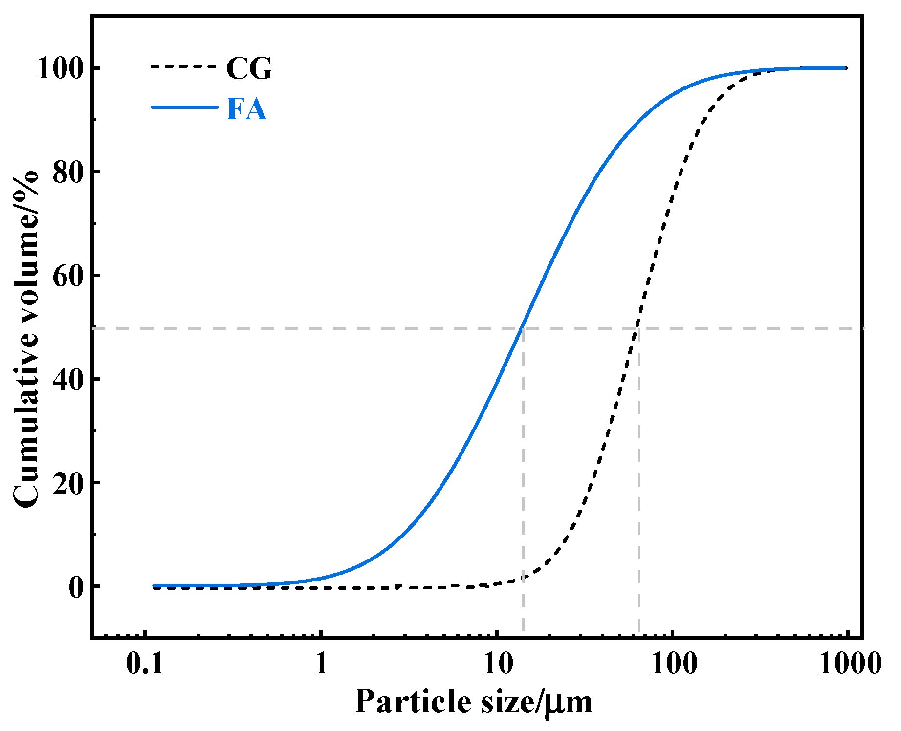
The raw materials used are coal gangue (CG) and fly ash (FA). Among them, the CG is provided by Northwest Mining Co., Ltd., Xi’an, China. The original CG has a large particle size and low activity, and it needs to be crushed and milled by a crusher and a ball mill. The FA is used conventional low-calcium FA (the CaO mass fraction is less than 10%), and the particle size distribution of the CG and FA is tested by a laser particle size instrument (Figure 1). The D50 of the CG and FA is 62.54 μm and 13.95 μm, respectively, and the D90 is 151.86 μm and 65.79 μm, respectively. The micromorphology of the CG and FA is analyzed by a scanning electron microscope analyzer (Figure 2). The surface of the CG is relatively rough, and the distribution of large and small particles is uneven. The FA contains more spherical glass beads. The chemical composition of the CG and FA is analyzed by an X-ray fluorescence spectrometer (XRF) (Table 1). The CG and FA mainly contain SiO2, Al2O3, CaO, and K2O. CO2 gas is provided by Qingdao Antaike Gas Co., Ltd., Qingdao, China, with a concentration greater than 99%, and it is food grade.

2.2. Test Methods

2.2.1. Slurry Preparation and Carbon Fixation Process

According to the ratio in Table 2, the CG and FA were first mixed evenly, and then tap water was added and stirred for 5 min. After the slurry was prepared, it was poured into a carbon fixation reactor. The operation process of the carbon fixation reactor is detailed in the literature [20]. The reactor conditions were maintained at 25 °C with 500 r/min agitation under 0.1 MPa gas pressure [24]. Following mixing, one slurry aliquot was transferred to a 500 mL beaker for rheological characterization, while another portion was cast into 30 mm cubical molds for subsequent microstructural analysis.

2.2.2. Carbon Sequestration Calculation

Thermogravimetric analysis of samples after curing for 3 days was performed using a TG 209 F3 Tarsus thermal analyzer from Netzsch, Germany. About 10 mg of the sample was placed in a crucible clamp for testing, with a sensitivity of 0.1 μg, an accuracy of 0.01%, a heating rate of 10 °C/min, and a temperature range of 30–1000 °C. CO2 absorption was calculated as follows:
W CO 2 ( % ) = W CaCO 3 , f W CaCO 3 , i M CaCO 3 × M CO 2 W solid × 100 %
where W CO 2 is the amount of carbon fixed in the CFS; W CaCO 3 , f is the amount of CaCO3 in the CFS; W CaCO 3 , i is the initial content of CaCO3 in the unfixed carbon sample; M CO 2 and M CaCO 3 are the molar masses of CO2 and CaCO3, respectively; and W solid is the mass of the sample.

2.2.3. Rheological Test

A rheometer (Anton Paar 92, Graz, Austria) was used to perform rheological tests on the CFS. The rheological test scheme was based on that in [25].

2.2.4. XRD Test

Some samples were taken and soaked in anhydrous ethanol for 24 h, and the anhydrous ethanol was changed every 12 h. Then, the samples were dried in a vacuum oven at 45 °C for 24 h and broken to 200 mesh. A D2 Phaser X-ray diffractometer from Bruker Company in Germany was used for the test, with a scanning speed of 5°/min and a scanning range of 5°~70°.

2.2.5. FTIR Test

The same hydration and crushing methods as in Section 2.2.4 were used for sample testing. A Nicolet iS20 spectrometer, produced by Thermo Scientific, Waltham, MA, USA, was used for sample testing. The sample was mixed and ground with KBr at a mass fraction of 1:100–1:200 and pressed at 30 MPa, and the scanning wavelength range was 400–4000 cm−1.

2.2.6. SEM Test

Sample morphology was examined using a ZEISS GeminiSEM 300 field-emission environmental scanning electron microscope (Oberkochen, Germany). The analysis was conducted at an accelerating voltage of 20 kV, with specimens prepared by gold sputter coating prior to imaging.

3. Results and Analysis

3.1. Effect of Carbon Fixation Time on Carbon Fixation Amount and Rheological Properties of CFS

3.1.1. Effect of Carbon Fixation Time on Carbon Fixation Amount of CFS

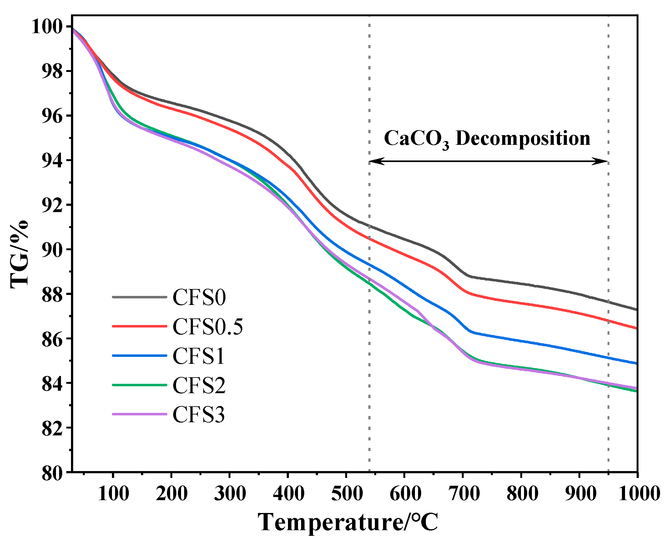
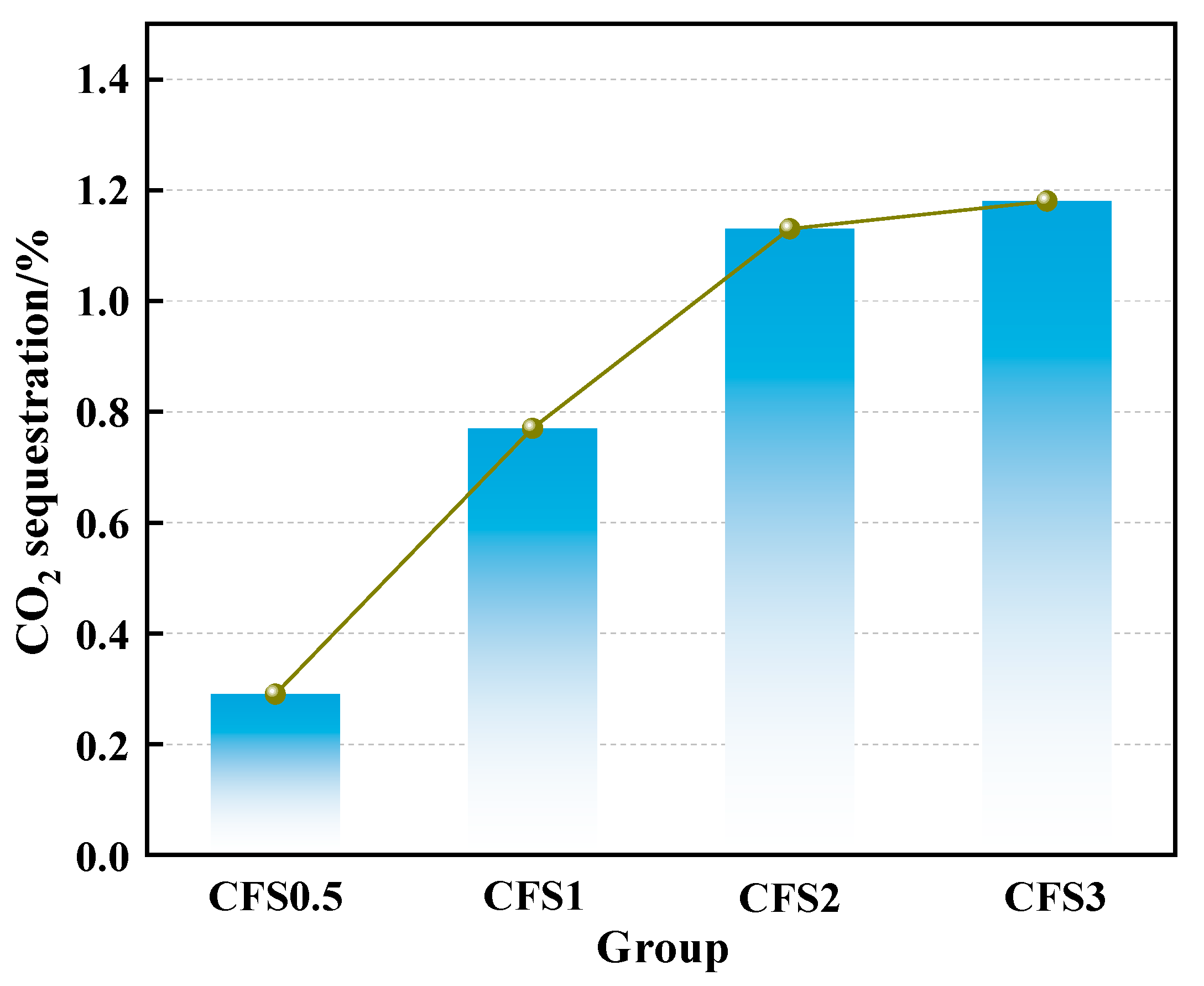
A TG curve of the CFS sample is shown in Figure 3. The mass loss from ambient temperature to 100 °C corresponds to the mass loss of water and hydrated gel (C-S-H) in the sample [26]. Under high-temperature conditions of 300~540 °C, the mass loss is due to the decomposition of calcium hydroxide [27]. The mass loss at 540~950 °C is due to the decomposition of calcium carbonate [28]. According to the calculation method of carbon fixation in Section 2.2.2, the carbon fixation amount of the CFS samples at different carbon fixation times is obtained, as shown in Figure 4. With an increase in the carbon fixation time, the CO2 storage capacity of the CFS samples shows a trend of increasing first and then tending to be flat. When the carbon fixation time is 2 h, the carbon fixation amount is 1.13%, and 1 ton of CFS can achieve a CO2 reduction of 11.3 kg compared to traditional filling after carbon fixation. When the carbon fixation time is greater than 2 h, the CO2 storage capacity remains basically unchanged. There are two main reasons for this: ① As the reaction proceeds, the active calcium ions in the filling slurry are gradually consumed, and the concentration of the reactants decreases. ② The calcium carbonate generated by the reaction is deposited on the surface of the particles to form a dense calcification layer, which hinders the diffusion of CO2 into the interior of the particles and inhibits the migration of internal calcium and magnesium ions to the outside [29].

3.1.2. Effect of Carbon Fixation Time on CFS Rheological Parameters

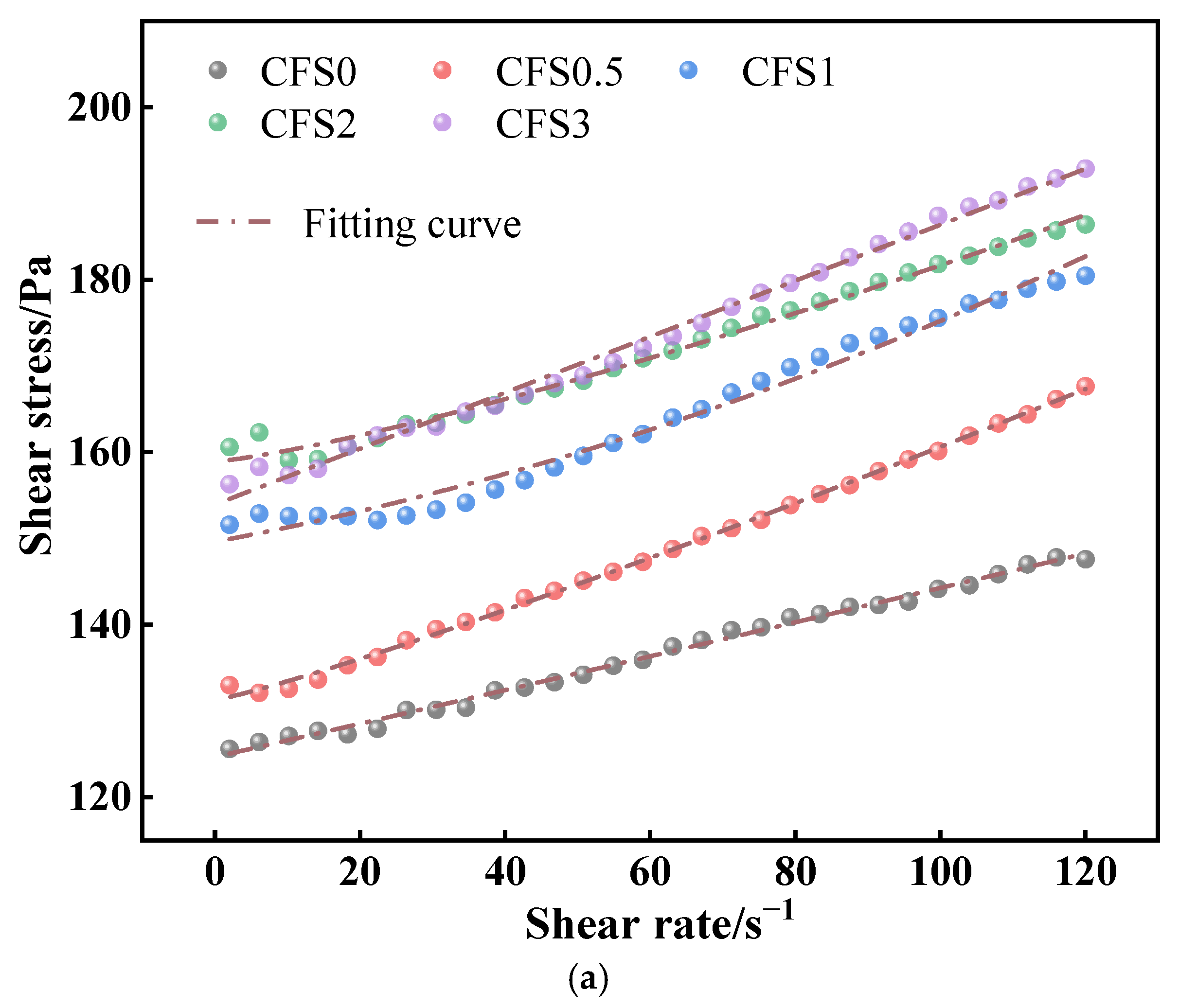
Figure 5a shows the relationship between the shear rate and shear stress of the CFS. As can be seen in the figure, the shear stress of the slurry increases with the increase in the carbon fixation time. This is mainly because, after the introduction of CO2, it will react chemically with the alkali metal ions (Ca2+ and Mg2+) in the slurry to generate carbonates, making the flocculation network structure inside the slurry complex, resulting in poor flow properties of the slurry. When the carbon fixation time is greater than 1 h, the shear stress increasing trend gradually slows down at the same shear rate. This is mainly because, as the carbon fixation time increases, the carbonates produced adhere to the surface of the particles, hindering their further reaction [30]. As shown in Figure 5b, at the same shear rate, the apparent viscosity change trend is the same as the shear stress change trend, but the reasons for the change are not introduced here [31].
By using the H-B model to fit the shear stress–shear rate curve, the plastic viscosity and yield stress of the slurry can be obtained, and the rheological equation is as follows [20]:
τ = τ0 + ηγn
When n = 1 and τ0 = 0, it is a Newtonian fluid; when n = 1 and τ0 > 0, it is a Bingham fluid; when n > 1, it is an expansion fluid; and when n < 1, it is a pseudoplastic fluid. The fitting results are shown in Table 3, and R2 is greater than 0.99, which has a good fitting effect.
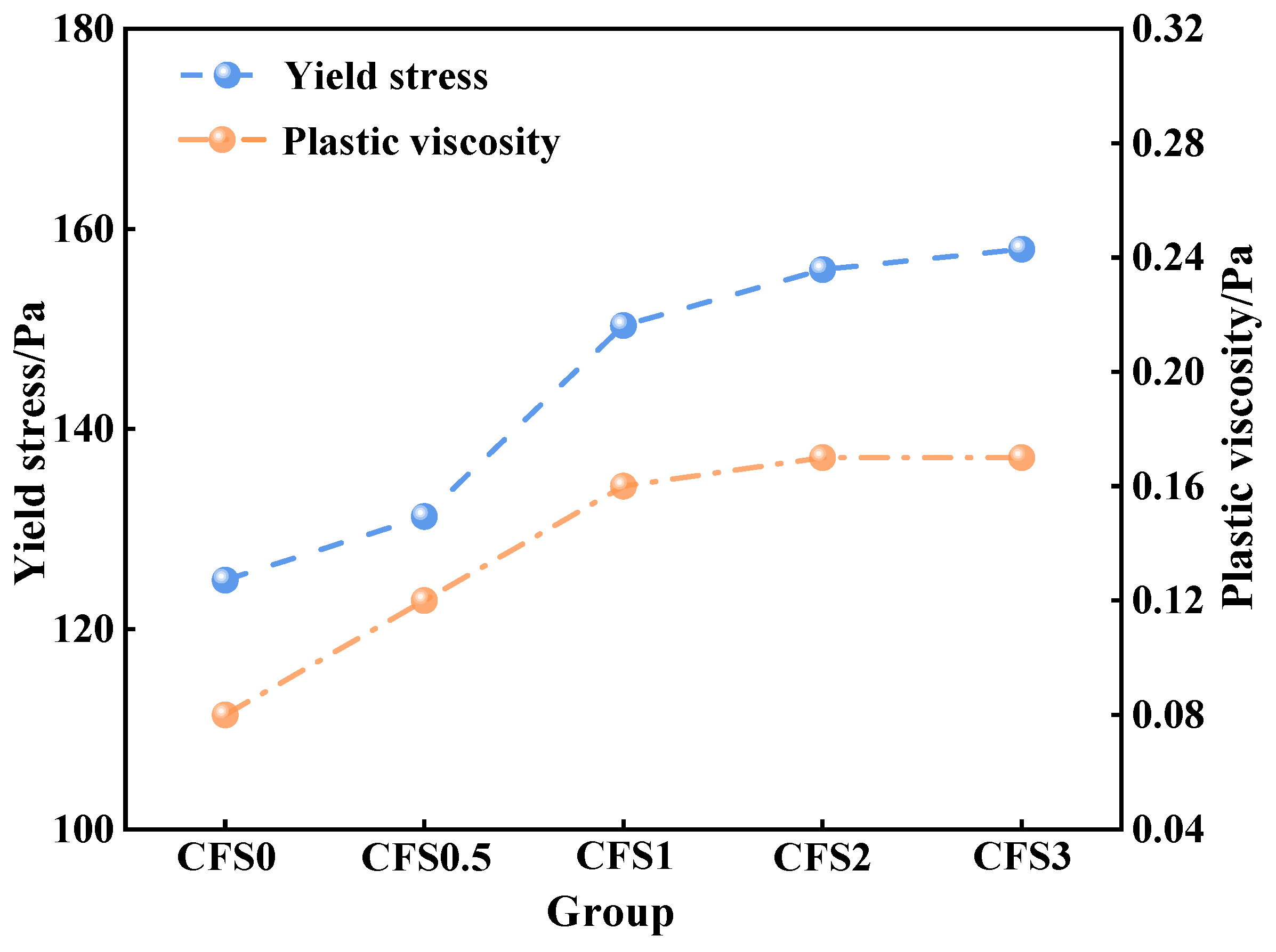
Figure 6 illustrates the dependence of the CFS yield stress and plastic viscosity on carbonation duration. The data indicate that both rheological parameters increased progressively with longer carbonation times. Specifically, yield stress rose from 124.89 Pa to 157.97 Pa (representing a 26% increase), while plastic viscosity increased from 0.08 Pa·s to 0.17 Pa·s (a 113% increase). Furthermore, the figure demonstrates that, beyond 1 h of carbonation, both yield stress and plastic viscosity stabilized, a phenomenon whose underlying mechanism was addressed in the preceding discussion.
Under the action of shear force, the upward and downward lines of the rheological curve of the slurry do not coincide, forming a hysteresis loop whose integral area can represent the thixotropic characteristics of the slurry. The hysteresis loop area is shown in Figure 7. As the carbon fixation time increases, the hysteresis loop area of the CFS gradually increases and then tends to stabilize, which is consistent with the trend of yield stress and plastic viscosity.

3.2. Effect of Carbon Fixation Time on the Composition and Microstructure of CFS

3.2.1. Morphology and Microstructure

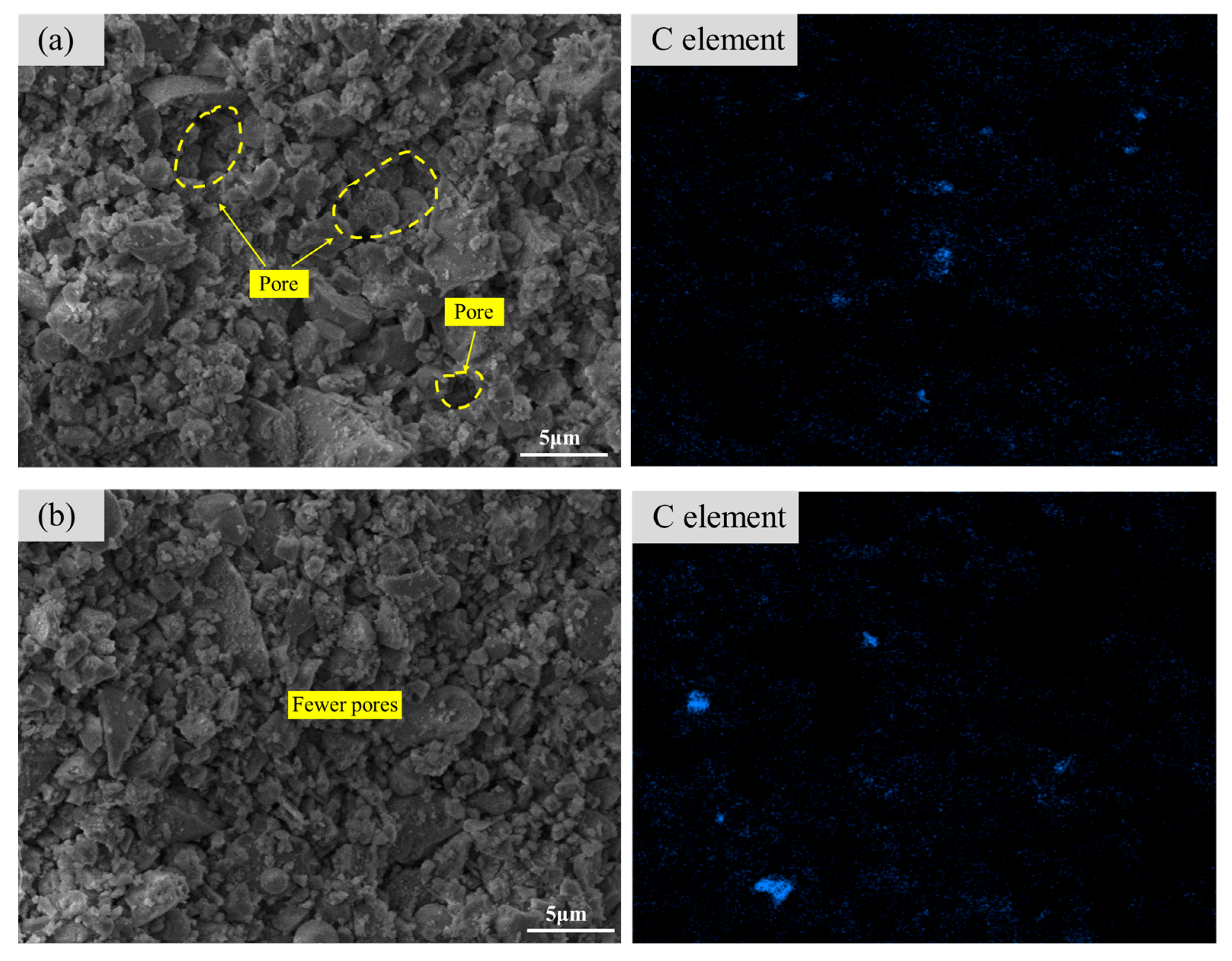
Figure 8 shows the SEM-EDS images of the CFS at different carbon fixation times. When carbon is not fixed, it can be observed that there are a large number of pores in the CFS, the particle distribution is relatively loose, and only a small amount of flocculent substances are observed on the particle surface. The friction between the particles is small, which helps the flow of the slurry. After carbon fixation for 3 h, it can be seen that the microstructure of the CFS sample becomes denser, and the pore structure decreases. This is because the accumulation of carbonation products fills the sample pores, resulting in the deterioration of the rheological properties of the slurry. Through the EDS elemental analysis, it can be seen that, compared with the unfixed carbon, the distribution of C elements in the CFS after carbon fixation increases, mainly from CO2, which further verifies that CO2 reacts with Ca ions to generate calcium carbonate.

3.2.2. XRD

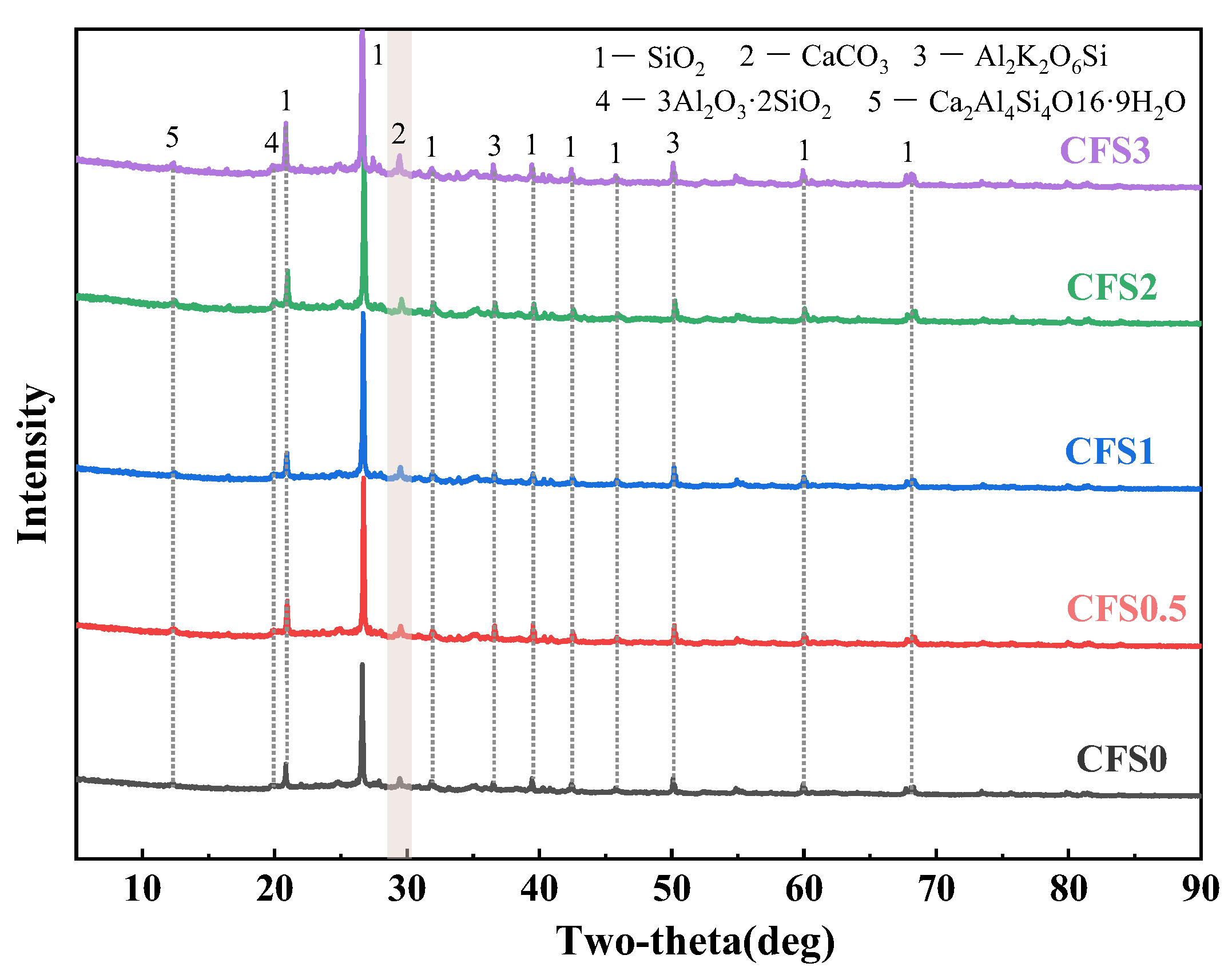
Figure 9 presents the XRD patterns of the CFS under varying carbonation conditions. These patterns reveal the emergence of a calcium carbonate (CaCO3) diffraction peak at 2θ ≈ 29.5° following carbonation treatment. This characteristic peak intensifies progressively with an extended carbonation duration, initially increasing before stabilizing—a trend aligning with the rheological observations detailed in Section 3.1. This is mainly because, as the carbon fixation time increases, the calcium ions in the filling slurry are gradually consumed by the reaction to generate carbonate products, which deteriorate the rheological properties of the slurry. After further increasing the carbon fixation time, the amount of calcium carbonate generated remains basically unchanged, and the yield stress and plastic viscosity of the slurry also tend to stabilize [32].

3.2.3. FTIR

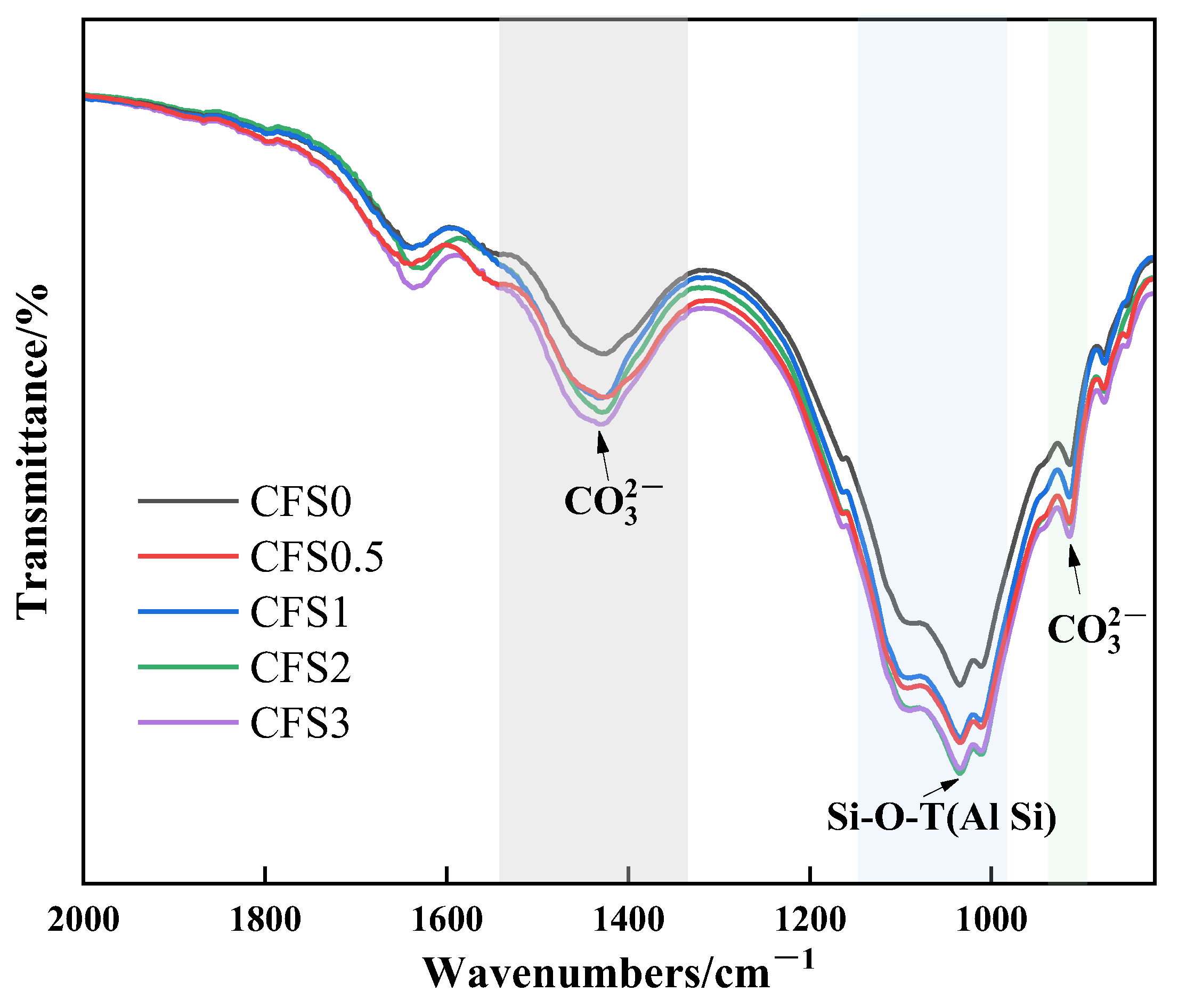
Figure 10 shows the FTIR spectra of the CFS at different carbon fixation times. The main infrared characteristic peaks of the CFS are as follows: (1) The stretching vibration peak at 1420 cm−1 and the bending vibration peak at 875 cm−1 correspond to the CO32− in carbonates such as CaCO3 in the sample. (2) The asymmetric stretching vibration peak at 1030~1050 cm−1 and the bending vibration peak at 460~465 cm−1 correspond to Si-O-T(Al Si) in CaO·Al2O3·2SiO2 [33,34]. By comparing the vibration peaks of CO32−, it can be seen that more CO32− is generated after CO2 is sealed compared with that before carbon fixation, resulting in an increase in the peak intensity, yield stress, and plastic viscosity of the slurry. As the carbon fixation time increases, the peak intensity variation decreases, which is consistent with the results of the XRD and thermogravimetric tests.

4. Conclusions

(1)
The carbon fixation amount of the CFS increases first and then tends to be stable with an increase in the carbonization time. When the carbon fixation time is 2 h, the carbon fixation amount is 1.13%.
(2)
After further increasing the carbon fixation time, the carbon fixation amount gradually tends to be stable. On the one hand, this is because the calcium ions in the solution are gradually consumed, and, on the other hand, it is because the generated calcium carbonate is deposited on the surface of the particles, thereby forming a calcification layer, which hinders the diffusion of CO2 into the particles.
(3)
Prolonged carbonation promotes calcium carbonate formation, which increases the packing density within the slurry microstructure. This microstructural evolution adversely impacts the rheological performance of the CFS. Combined with the CO2 storage capacity, 2 h can be used as the optimal carbonization time. At this time, the yield stress and plastic viscosity of the CFS are 155.93 Pa and 0.17 Pa·s, respectively.
(4)
After the CFS fixes carbon, the generated calcium carbonate and hydration products fill the pores of the sample, making the microstructure of the CFS denser and the pore structure reduced.
This study delves into the influence of carbon fixation time on the carbon sequestration amount and rheological properties of CFS, providing valuable guidance for improving the carbon reduction and processability of CFS in practical engineering applications. However, the economy, carbon sequestration effect, and feasibility of CFS in practical engineering applications are also crucial and worthy of further research.

Author Contributions

H.L., writing—review and editing, resources, and funding acquisition; Q.G., writing—review and editing, writing—original draft, software, and data curation; Y.C., writing—original draft and visualization; Y.Z., data curation and supervision; B.H., writing—review and editing, project administration, and funding acquisition; M.L., data curation. All authors have read and agreed to the published version of the manuscript.

Funding

This work was supported by the National Key R&D Program of China [2023YFC3904300] and the National Natural Science Foundation of China [52304160].

Data Availability Statement

The original contributions presented in this study are included in the article. Further inquiries can be directed to the corresponding author.

Conflicts of Interest

Authors Haiquan Liu and Yong Chen are employed by Yankuang Energy Group Company Limited, and the remaining authors declare that the research was conducted in the absence of any commercial or financial relationships that could be construed as a potential conflict of interest.

References

  1. Zhang, X.Y.; Li, C.Q.; Zheng, S.L.; Di, Y.H.; Sun, Z. A review of the synthesis and application of zeolites from coal-based solid wastes. Int. J. Miner. Metall. Mater. 2022, 29, 1–21. [Google Scholar] [CrossRef]
  2. Shahmansouri, A.A.; Zhang, Z.G.; AzariJafari, H.; Shi, X.M. Biochar-amended high-strength engineered cementitious composites. Cem. Concr. Compos. 2025, 164, 106219. [Google Scholar] [CrossRef]
  3. Long, H.; Gu, Z.D.; Qin, Y.; Xing, A.X.; Cheng, R.D. Synergistic preparation of cemented backfill from multiple coal-based solid wastes and investigation of its properties. Mater. Today Commun. 2025, 47, 113025. [Google Scholar] [CrossRef]
  4. Ren, S.H.; Jiao, X.M.; Zheng, D.Z.; Zhang, Y.N.; Xie, H.P.; Guo, Z.Q. Demand and fluctuation range of China’s coal production under the dual carbon target. Energy Rep. 2024, 11, 3267–3282. [Google Scholar]
  5. Tang, T.; Wang, Z.; Chen, L.Z.; Wu, S.; Liu, Y.S. Opportunities, challenges and modification methods of coal gangue as a sustainable soil conditioner—A review. Environ. Sci. Pollut. Res. 2024, 31, 58231–58251. [Google Scholar] [CrossRef] [PubMed]
  6. Xue, L.M.; Li, M.J.; Zheng, Z.X.; Xi, S.Y.; Yang, Y.H.; Yang, W.L. Assessing the progress of the mining industry towards green growth in China: A three-stage dynamic network slacks-based measure approach. J. Clean. Prod. 2024, 435, 140478. [Google Scholar] [CrossRef]
  7. Mora-Herrera, D.; Pal, M. Effect of Ge content on diode parameters of superstrate type Cu2ZnSn1−xGexS4/CdS heterostructures prepared by all-solution process. J. Mater. Sci. 2024, 59, 2416–2436. [Google Scholar] [CrossRef]
  8. Xiong, Y.; Kong, D.Z.; Song, G.F. Research hotspots and development trends of green coal mining: Exploring the path to sustainable development of coal mines. Resour. Policy 2024, 92, 105039. [Google Scholar] [CrossRef]
  9. Xu, H.X.; Wu, W.; Shi, B.; Liu, L.B.; Cao, Y.J.; Deng, J.S.; Cui, J.S.; Cui, J.H.; Wang, J.Z.; Kang, Y.T.; et al. Research on carbon emission accounting and carbon emission reduction path of coal preparation plant. Miner. Eng. 2024, 217, 108955. [Google Scholar] [CrossRef]
  10. Gao, P.; Yue, S.J.; Chen, H.T. Carbon emission efficiency of China’s industry sectors: From the perspective of embodied carbon emissions. J. Clean. Prod. 2021, 283, 124655. [Google Scholar] [CrossRef]
  11. Tan, B.Y.; Xu, F.Y.; Guo, Y.Z.; Ramsey, T. Analysis of the characteristics and robustness of China’s inter-industry carbon transfer complex network based on hypergraph. J. Clean. Prod. 2025, 523, 146424. [Google Scholar] [CrossRef]
  12. Wang, H.Q.; Shang, L.; Tang, D.C.; Li, Z.J. Research Themes, Evolution Trends, and Future Challenges in China’s Carbon Emission Studies. Sustainability 2024, 16, 2080. [Google Scholar] [CrossRef]
  13. Huang, J.Y.; Li, H.Z.; Tang, C.; Guo, G.L.; Yuan, Y.F. Carbon sequestration in coal mine goafs: Innovations in high-water material solidification with supercritical carbon dioxide for global carbon neutrality initiatives. Clean Technol. Environ. Policy 2025, 1–15. [Google Scholar] [CrossRef]
  14. Qian, S.; Xu, J.Z.; Wei, Z.H.; Liu, H.C.; Sun, P.Q.; Zhai, C.; Liu, T.; Wang, Y.; Xu, H.X. Study on the influence of carbide slag incorporation on the carbon sequestration efficiency and material properties of fly ash-based carbon-negative filling materials. Constr. Build. Mater. 2025, 489, 142381. [Google Scholar] [CrossRef]
  15. Edwards, R.W.J.; Celia, M.A.; Bandilla, K.W.; Doster, F.; Kann, C.M. A Model To Estimate Carbon Dioxide Injectivity and Storage Capacity for Geological Sequestration in Shale Gas Wells. Environ. Sci. Technol. 2015, 49, 9222–9229. [Google Scholar] [CrossRef] [PubMed]
  16. Agrawal, K.A.; Mehra, A. Dunite carbonation in batch-tubular reactor. Environ. Sci. Pollut. Res. 2020, 27, 31439–31445. [Google Scholar] [CrossRef]
  17. Gu, T.; Min, Q.S.; Zeng, X.L.; Wu, L.Y.; Wang, M.; Zhang, L.H.; Liu, L.B. Effects of calcium carbide slag on properties and carbon sequestration efficiency of cement pastes mixed under direct CO2 injection conditions. J. CO2 Util. 2024, 84, 102835. [Google Scholar] [CrossRef]
  18. Li, Y.; Fu, J.X.; Jing, P.Y.; Wang, J.; Wang, K. Experimental study on the macroscopic and microscopic properties of cement paste backfill after treatment with carbon dioxide carbonize filling slurries during the mixing process. J. Mater. Res. Technol. 2024, 33, 1654–1666. [Google Scholar] [CrossRef]
  19. Zhang, X.; Su, Y.L.; Liu, S.S. The effect of carbonation pressure on microbial assisted steel slag-based carbon sequestration material. J. Build. Eng. 2024, 86, 108974. [Google Scholar] [CrossRef]
  20. Guo, Q.; Zhang, J.X.; Li, M.; Huo, B.B.; Zhao, Y.; Yin, Z.J.; Xing, S.H.; Fu, X.H. Rheological and CO2 sequestration properties of alkali-activated gangue-based backfill slurry: Effect of temperature. J. Mater. Res. Technol. 2025, 36, 3886–3897. [Google Scholar] [CrossRef]
  21. Wang, B.; Cheng, H.G.; Liu, X.; Di, Z.C.; Song, H.P.; Zhang, D.K.; Cheng, F.Q. CO2 Mineralized Full Solid Waste Cementitious Material for Coal Mine Goaf Filling and Carbon Sequestration Potential Assessment. Engineering 2025, 48, 70–80. [Google Scholar] [CrossRef]
  22. Zhu, L.; Liu, Z.C.; Guo, Q.; Huo, B.B.; Zhou, N.; Zhou, Y.J.; Li, M.; Gu, W.Z. Effect of Carbonization Pressure on CO2 Sequestration and Rheological Properties of Coal Gangue-Based Backfilling Slurry. Appl. Sci. 2025, 15, 1656. [Google Scholar] [CrossRef]
  23. Liu, L.; Xia, L.; Fang, Z.Y.; Jia, Q.F.; Gao, Y.H.; He, W.; Liu, Z.Z. Performance study of modified magnesium-coal based solid waste negative carbon backfill material: Strength characteristics and carbon fixation efficiency. J. Environ. Chem. Eng. 2024, 12, 113281. [Google Scholar] [CrossRef]
  24. Qian, C.X.; Pei, J.W.; Fan, Y.J.; Zhang, X. Steel slag powder-CO2 contact state in static or rotary process of carbon fixation. Chem. Eng. J. 2024, 496, 153958. [Google Scholar] [CrossRef]
  25. Shao, C.C.; Liu, L.; Zhang, X.Y.; Xie, L.; Ruan, S.S.; Zhu, M.B.; Yang, P.Y.; Liu, D.S. Influence of internal and external factors on the fluidity of modified magnesium slag-based backfill materials. J. Environ. Chem. Eng. 2024, 12, 111867. [Google Scholar] [CrossRef]
  26. Lu, B.; He, P.P.; Liu, J.H.; Peng, Z.Y.; Song, B.X.; Hu, X. Microstructure of Portland cement paste subjected to different CO2 concentrations and further water curing. J. CO2 Util. 2021, 53, 101714. [Google Scholar] [CrossRef]
  27. Xian, X.P.; Zhang, D.; Shao, Y.X. Flue gas carbonation curing of cement paste and concrete at ambient pressure. J. Clean. Prod. 2021, 313, 127943. [Google Scholar] [CrossRef]
  28. Rostami, V.; Shao, Y.X.; Boyd, A.J.; He, Z. Microstructure of cement paste subject to early carbonation curing. Cem. Concr. Res. 2012, 42, 186–193. [Google Scholar] [CrossRef]
  29. Wang, C.y.; Bao, W.J.; Guo, Z.C.; Li, H.Q. Carbon Dioxide Sequestration via Steelmaking Slag Carbonation in Alkali Solutions: Experimental Investigation and Process Evaluation. Acta Metall. Sin. (Engl. Lett.) 2018, 31, 771–784. [Google Scholar] [CrossRef]
  30. Zhang, Q.; Pan, F.; Shen, X.Y.; Lu, J.Y.; Ye, S.X.; Wang, H.C.; Ling, T.C.; Ran, Q.P. Utilization of solid wastes to sequestrate carbon dioxide in cement-based materials and methods to improve carbonation degree: A review. J. CO2 Util. 2023, 72, 102502. [Google Scholar] [CrossRef]
  31. Xin, J.; Liu, L.; Xu, L.H.; Wang, J.Y.; Yang, P.; Qu, H.S. A preliminary study of aeolian sand-cement-modified gasification slag-paste backfill: Fluidity, microstructure, and leaching risks. Sci. Total Environ. 2022, 830, 154766. [Google Scholar] [CrossRef]
  32. Li, T.; Nogueira, R.; de Brito, J.; Liu, J.P. Quantitative analysis of the influence of fine aggregate’s grading on mortar’s rheology. J. Mater. Res. Technol. 2023, 25, 310–318. [Google Scholar] [CrossRef]
  33. Ma, L.C.; Wu, J.S.; Zhao, M.; Li, X.R.; Han, P.; Song, G.J. Modification of carbon fibers surfaces with polyetheramines: The role of interphase microstructure on adhesion properties of CF/epoxy composites. Polym. Compos. 2018, 39 (Suppl. S4), E2346–E2355. [Google Scholar] [CrossRef]
  34. Hsiao, M.C.; Liao, S.H.; Yen, M.Y.; Liu, P.L.; Pu, N.W.; Wang, C.A.; Ma, C.M. Preparation of Covalently Functionalized Graphene Using Residual Oxygen-Containing Functional Groups. ACS Appl. Mater. Interfaces 2010, 2, 3092–3099. [Google Scholar] [CrossRef] [PubMed]
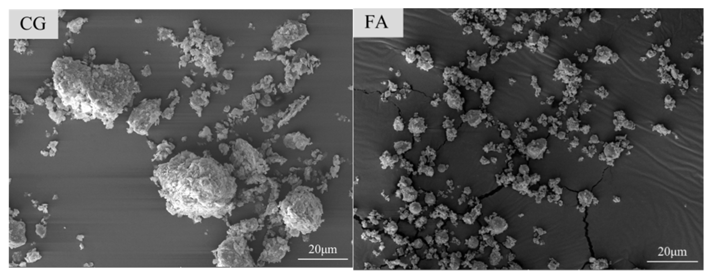
Figure 1. SEM of CG and FA.
Carbon 11 00071 g001
Figure 2. Particle size distribution of raw material.
Carbon 11 00071 g002
Figure 3. TG curves of CFS samples at different carbon fixation times, where CFS0 represents non-fixed carbon, and CFS0.5, CFS1, CFS2, and CFS3 represent carbon fixation times of 0.5, 1, 2, and 3 h, respectively.
Carbon 11 00071 g003
Figure 4. Carbon fixation amount of CFS samples at different carbon fixation times, where CFS0.5, CFS1, CFS2, and CFS3 represent carbon fixation times of 0.5, 1, 2, and 3 h, respectively.
Carbon 11 00071 g004
Figure 5. (a) Shear stress–shear rate. (b) Apparent viscosity–shear rate relationship of CFS at different carbon fixation times.
Carbon 11 00071 g005aCarbon 11 00071 g005b
Figure 6. Yield stress and plastic viscosity of CFS at different carbon fixation times.
Carbon 11 00071 g006
Figure 7. Relationship between hysteresis loop area and carbon fixation times of CFS.
Carbon 11 00071 g007
Figure 8. SEM-EDS images of CFS at different carbon fixation times: (a) CFS0 and (b) CFS3.
Carbon 11 00071 g008
Figure 9. XRD patterns of CFS at different carbon fixation times.
Carbon 11 00071 g009
Figure 10. FTIR spectra of CFS at different carbon fixation times.
Carbon 11 00071 g010
Table 1. Chemical composition of raw material, wt%.
No.SiO2Al2O3Fe2O3CaOK2OMgONa2OTiO2SO3
CG54.4522.889.640.983.642.711.921.081.46
FA56.7927.254.613.282.451.210.631.381.79
Table 2. Slurry mixing ratio.
CroupCementitious MaterialsWater–Binder RatioCarbon Sequestration Time/h
CGFA
CFS080%20%0.50
CFS0.50.5
CFS11
CFS21.5
CFS32
Table 3. Fitting rheological model of CFS at different carbon fixation times.
No.Rheological ModelFitting Resultsτ0/Paη/Pa·sR2
CFS0H-Bτ = 124.89 + 0.08γ0.86124.890.080.9987
CFS0.5τ = 131.27 + 0.12γ0.84131.270.120.9989
CFS1τ = 150.34 + 0.16γ0.92150.340.160.9995
CFS2τ = 155.93 + 0.17γ0.97155.930.170.9992
CFS3τ = 157.97 + 0.17γ0.98157.970.170.9994
Disclaimer/Publisher’s Note: The statements, opinions and data contained in all publications are solely those of the individual author(s) and contributor(s) and not of MDPI and/or the editor(s). MDPI and/or the editor(s) disclaim responsibility for any injury to people or property resulting from any ideas, methods, instructions or products referred to in the content.