Article

Tribological Properties and Wear Mechanisms of Carbide-Bonded Graphene Coating on Silicon Substrate

1
School of Mechanical Engineering, Hefei University of Technology, Hefei 230009, China
2
Sino-German College of Intelligent Manufacturing, Shenzhen Technology University, Shenzhen 518118, China
*
Author to whom correspondence should be addressed.
Submission received: 29 July 2025 / Revised: 4 September 2025 / Accepted: 11 September 2025 / Published: 15 September 2025
(This article belongs to the Topic Application of Graphene-Based Materials, 2nd Edition)

Abstract

Carbide-bonded graphene (CBG) coating, with its unique 3D cross-linked network structure, shows significant potential for protecting silicon substrates. However, a comprehensive understanding of its macroscale tribological properties remains lacking. This study investigated the macroscale friction and wear behaviors of CBG-coated silicon wafers using reciprocating sliding tests against steel balls under various loads and sliding cycles. The CBG coating exhibited excellent friction-reduction and anti-wear performance, reducing the steady friction coefficient from 0.80 to 0.17 and wear rate by an order of magnitude compared to those of bare silicon. Higher loads slightly decreased both friction coefficients and wear rates, primarily due to the formation of denser tribofilms and transfer layers. Re-running experiments revealed three distinct wear stages—adhesive, abrasive, and accelerated substrate wear—driven by the evolution of tribofilms, transfer layers, and unabraded flat areas. Furthermore, comparative experiments confirmed that these “unabraded flat areas” on the wear track play a critical role in sustaining low friction and prolonging coating life. The findings identify CBG as a robust solid lubricant for high-contact-pressure applications and emphasize the influence of tribo-layer dynamics and wear debris behavior on coating performance.

Graphical Abstract

1. Introduction

Graphene, a two-dimensional nanomaterial composed of carbon atoms arranged in a hexagonal lattice, has been widely used for its excellent mechanical, thermal, and electrical properties [1,2,3]. Notably, graphene exhibits remarkable tribological performance as an effective solid lubricant. For instance, when used as coatings for steel tribo-pairs, few-layer graphene coatings decreased wear by almost four orders of magnitude and friction coefficients by six-fold compared to bare steel [4]. Even a single layer of graphene can last for 6400 sliding cycles in pin-on-disk wear tests against steel, despite a relatively high contact pressure of 0.5 GPa [5]. Graphene tribology across different scales has been a highly active research area ever since graphene’s discovery.
Various types of structural defects may be introduced during the synthesis of graphene. Therefore, graphene products in most applications are actually graphene derivatives [6,7,8]. Despite possibly lower performance, graphene derivatives still could be attractive for tribological applications concerning the economic aspects. Among these, carbide-bonded graphene (CBG) is a three-dimensional cross-linked graphene network, first synthesized by Lee et al. [9]. The unique 3D structures not only preserve the inherent features of graphene but also enhance the bonding between layers and the substrate via interatomic covalent bonds [10,11]. As a result, the CBG coating exhibited superior properties, including strong mechanical performance, high thermal and electrical conductivity. For example, a 45 nm thick CBG coating showed a Hertzian hardness of 345.2 ± 22.3 GPa, and a 600 nm thick graphene network on a ceramic substrate had an electrical conductivity of 3.31 × 10⁶ S/m, 20 times higher than that of natural graphite [9]. In particular, CBG coatings deposited on silicon molds can serve as both an anti-sticking coating and a resistive heating source, and thus has found various applications in glass-forming areas [12,13]. To ensure its long-term durability as a protective coating, excellent tribological behaviors are required, such as low friction and superior anti-wear performance. Nonetheless, only limited studies have investigated the tribological behaviors of CBG coatings [14,15,16]. For example, Garman et al. [17] performed micro- and nano-scale friction tests on ultra-thin graphene coatings (thickness range: 4–80 nm) with applied loads ranging from 0 to 1800 nN. The friction coefficient of the SiO2/Si wafer was reduced from 0.0656 to 0.0547 with a silicon oxycarbide-bonded graphene network. Zhou et al. [18] investigated the friction and wear behaviors of graphene-coated silicon molds for high-temperature glass molding (660–700 °C) using barrel compression tests. In their experiments, the applied load ranged from 75 N to 300 N, with the friction coefficient remaining stably in the range of 0.19–0.25. In short, the tribological performance of CBG coatings varies under different test conditions and methods, thus necessitating further standardized experimental investigations.
The ability to withstand high contact pressure is crucial for coating applications. Many studies have focused on the effect of load on the macroscopic tribological behavior of coatings. Berman et al. [19] found that graphene provides more pronounced protection at lower loads, while the graphene layer is worn out or quickly removed from the wear track under higher loads. Bhowmick et al. [20] concluded that the higher the load, the larger the fluctuations persisted in the friction coefficient curve, and that the friction coefficient was positively correlated with the load. For instance, Wang et al. [21] found that, for the graphene-coated surface with the normal load varying from 1 N to 6 N, the larger normal load was beneficial for reducing the friction coefficient. Toosinezhad et al. [22] found that the Co/G composite coating maintained the lowest average friction coefficient (ranging from 0.60 at 5 N to 0.46 at 15 N) across all loads, attributed to the solid lubrication effect of graphene. Different from the previous two studies, in this work, the low friction coefficient was attributed to the formation of a lubricious tribo-layer between the counterbody and the coating rather than shearing or atomic adsorption.
To explain the friction and wear mechanisms of coatings, the evolution and role of the tribo-layers have been frequently discussed. When debris transfers from a low-surface-energy surface to a high-surface-energy surface, a “transfer layer” [23] forms on the high-surface-energy surface. Correspondingly, a protective layer referred to as “tribofilm” [24] forms from the accumulation of debris at the sliding contact zone of the low-surface-energy surface. The transfer layer and tribofilm together constitute the lubricious tribo-layers. Numerous studies have shown their beneficial effects. In the study of the tribological behavior of in situ exfoliated graphene, the graphene-enhanced lubricants offered 81.3% reduction in friction coefficient and 61.8% reduction in wear scar diameter due to the presence of a tribofilm [25]. A low friction coefficient of about 0.05 was obtained because of the formation of the transfer layer, and the thickness of the transfer layer had important influences on the tribological properties of graphene [26]. Hu et al. [27] reported that the sp2 nanocrystallites facilitated the formation of transfer film for stable low friction, as confirmed by in situ TEM nanofriction tests. Wahl et al. [28] presented a method to monitor and quantify the thickness of the transfer film during in situ tribological studies based on Newton’s rings analysis. In summary, the thickness and operating mechanisms of the tribo-layers primarily influence the tribological properties of the coatings.
Herein, the macroscale tribological properties of the CBG coating were fully investigated by employing a reciprocating sliding procedure. First, comparative tests were used to examine the friction reduction and wear resistance of the CBG coating. Then the dependence of tribological properties on load was investigated. In addition, a re-running experimental scheme was used to investigate the wear mechanisms of the coating, focusing on the relationship between the synergistic actions of the tribofilm, transfer layer and the tribological properties. Furthermore, the presence of unabraded flat areas (simplified to “flat areas”) on the coating wear track was identified, and the effect of the flat areas on the tribological properties was discussed.

2. Materials and Methods

2.1. Preparation and Characterization of CBG Coating

The CBG coating on the silicon substrate was prepared using the chemical vapor deposition (CVD) method presented in reference [29]. A brief introduction on the deposition process was made as follows. Methane was chosen as the primary carbon source, and 99.8% pure solid polydimethylsiloxane (PDMS) was used as the silicon source. A silicon wafer (30 mm × 30 mm × 1 mm) and 2.0 g of PDMS were placed in a quartz tube furnace (length: 60 cm; inner diameter: 5.08 cm. Kejia Furnace Co., Ltd., Zhengzhou, China). First, the tube was evacuated to remove air, after which it was purged with argon gas. Then, the tube temperature was raised at a rate of 20 °C/min from room temperature to 1050 °C under a continuous argon flow of 30 sccm [29]. Once the temperature reached the optimal coating deposition temperature, methane and argon were introduced simultaneously at a rate of 30 sccm. The temperature was held constant for 30 min to allow the CBG coating to grow freely through reactions between silicon-related radicals from the silicon source and carbon radicals from methane [9,15]. Finally, the furnace was cooled to room temperature by natural cooling with all gases turned off. The CBG-coated silicon wafers were cleaned with water and acetone to remove possible dust contamination.
The surface quality, microstructure, and chemical compositions of the CBG coating were characterized. Atomic force microscopy (AFM, Bruker Nano Caliber™, Saarbrücken, Germany) was used to measure surface roughness, as shown in Figure 1a,b. The arithmetic mean surface roughness (Sa) of bare silicon wafers was approximately 0.18 nm, while that of CBG coating was 0.46 nm. Hence, the deposition quality of the CBG coating surface was high. The cross-sectional microstructure was observed using a high-resolution transmission electron microscope (HRTEM, JEM-2100F, JEOL Ltd., Tokyo, Japan). As shown in Figure 1c, the CBG coating thickness was 234 nm. The magnified HRTEM image (Figure 1d) revealed a slightly wavy stacked-layer structure along the direction of thickness, with an average interlayer spacing of ~0.36 nm. Consistent with previous reports [9,11], CBG coating growth is dominated by preferential in-plane (x–y) deposition, followed by covalent interlayer bonding along the z-direction. During vertical growth, minor interlayer deviations generate structural fluctuations, producing the observed waviness. Figure 1d shows that the waviness amplitude was <1 nm with a fluctuation period of several nanometers. Because these features are below the lateral resolution limit of AFM, they could not be resolved in AFM scans. Consequently, AFM characterization (Figure 1b) presented the coating surface as smooth, high-quality morphology.
The chemical compositions of the CBG coating were tested using an X-ray photoelectron spectrometer (XPS, ESCALAB250Xi, Thermo Fisher Scientific Inc., Waltham, MA, USA). The atomic content of each element was evaluated in terms of the area intensity under composition survey spectra [30]. All spectra were carefully processed using the AvantageTM V6 software package, with Shirley background subtraction performed to eliminate interference. Peak fitting was performed using Gaussian-Lorentzian (GL) functions, and the spectra were calibrated against the C=C peak in the C1s spectrum. As seen from the full XPS spectrum (Figure 2a), carbon, oxygen, and silicon were three main elements in the CBG coatings with atomic concentrations of 84.13%, 12.59%, and 3.28%, respectively. Furthermore, the C=C and C-C peaks in the C1s spectra, as shown in Figure 2b, were located at 284.4 eV and 284.8 eV. In this case, the sp2/sp3 ratio was estimated to be 1.4, indicating that the CBG coating was mainly composed of sp2 carbon sites [29]. In addition, the presence of functional groups like C-Si, C-Si-O, C-O, C-Si-O, and C-O-Si-O-C was detected in the C1s and Si2p energy spectra, as shown in Figure 2b,c. These stable covalent bonds strongly bond to the graphene layers, preventing easy interlayer slip. Raman measurements were obtained with LabRam HR Evolution (HORIBA Jobin Yvon, Paris, France) at a wavelength of 532 nm in the range of 1000 cm−1 to 3500 cm−1. Three peaks can be found in Figure 2d. The D peak located at 1355 cm−1, which was correlated with the degree of defects in the coating, and the G peak located at 1594 cm−1, a characteristic feature of sp2 carbon bonds in graphene [31,32]. The intensity ratio of the D peak to the G peak (ID/IG) was roughly 0.98. The 2D peak at 2750 cm−1 had a very low intensity (I2D/IG = 0.22). These results were consistent with the representative features of multilayer graphene [33,34].

2.2. Tribological Test Procedure

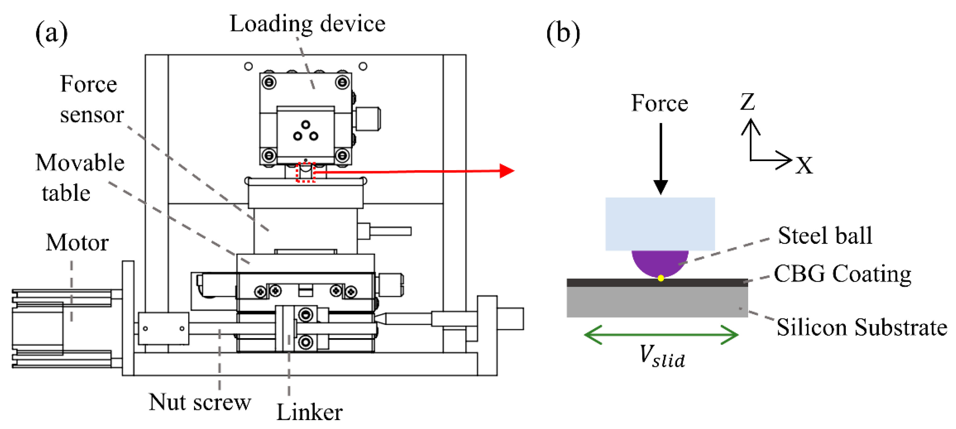
Tribological tests were carried out on a custom-built linear reciprocating tribometer, as shown in Figure 3. Prior to each test, the movable table was adjusted to maintain a horizontal position throughout the sliding process. Applied normal loads were independently calibrated using a vertical force module to ensure loading accuracy. Frictional forces during sliding were measured using a three-dimensional force sensor. Mounted directly beneath the sample stage and synchronized with the movable platform, the sensor provided 0.01 N resolution over a 0–10 N range for high-precision detection of subtle frictional variations. Applied normal loads were independently measured using a vertical force module to ensure loading accuracy. Prior to each test series, the tangential friction sensor was calibrated using national metrology-traceable standard weights, with calibration points (0 N, 0.5 N, 1 N, 3 N, and 5 N) covering the actual force range. Sensor outputs were linearized via software correction to eliminate systematic errors. The friction coefficient was calculated by the tribometer control system as the ratio of measured frictional force to normal load. During the experiment, the movable table was controlled by a motor via the screw to realize the linear reciprocating motion.
The samples used for wear tests had a size of 10 mm × 10 mm × 1 mm. A 6 mm diameter bearing steel ball with a surface roughness (Sa) of ~15 nm was used as the counterbody. The reciprocal sliding speed was 1 mm/s, with a one-way sliding distance of 1.5 mm. All tests were carried out in air with a relative humidity of 35–55% at room temperature. For the same set of parameters, at least three trials were performed to ensure data reliability.
After the tests, 3D confocal laser scanning microscope (VK-X250, Keyence, Osaka, Japan) and scanning electron microscope (SEM, Gemini 500, Carl Zeiss AG, Oberkochen, Germany) were used to characterize the surfaces of the silicon wafer and steel ball. The wear rate of the CBG coating, w c , was calculated using the following equations [35]:
w c = V c F L
V c = V t V s
where F is the normal load, L is the sliding distance, V c is the wear volume of the coating, V t is the total wear volume, and V s is the wear volume of the silicon substrate.
The wear rate of the steel balls was calculated as follows:
w b a l l = π d 4 64 r F L
where d is the diameter of the wear scar and r is the ball’s radius. The values of V t , V s , and d were obtained by analyses of 3D confocal laser microscope. After a 3D morphology image was calibrated horizontally, the total concave volume V t on the scratch zone was measured using the volume function provided by the analysis software, and the substrate’s wear volume V s was measured as the volume exceeding the coating’s thickness.

2.3. Quantitative Characterization of Worn Coating

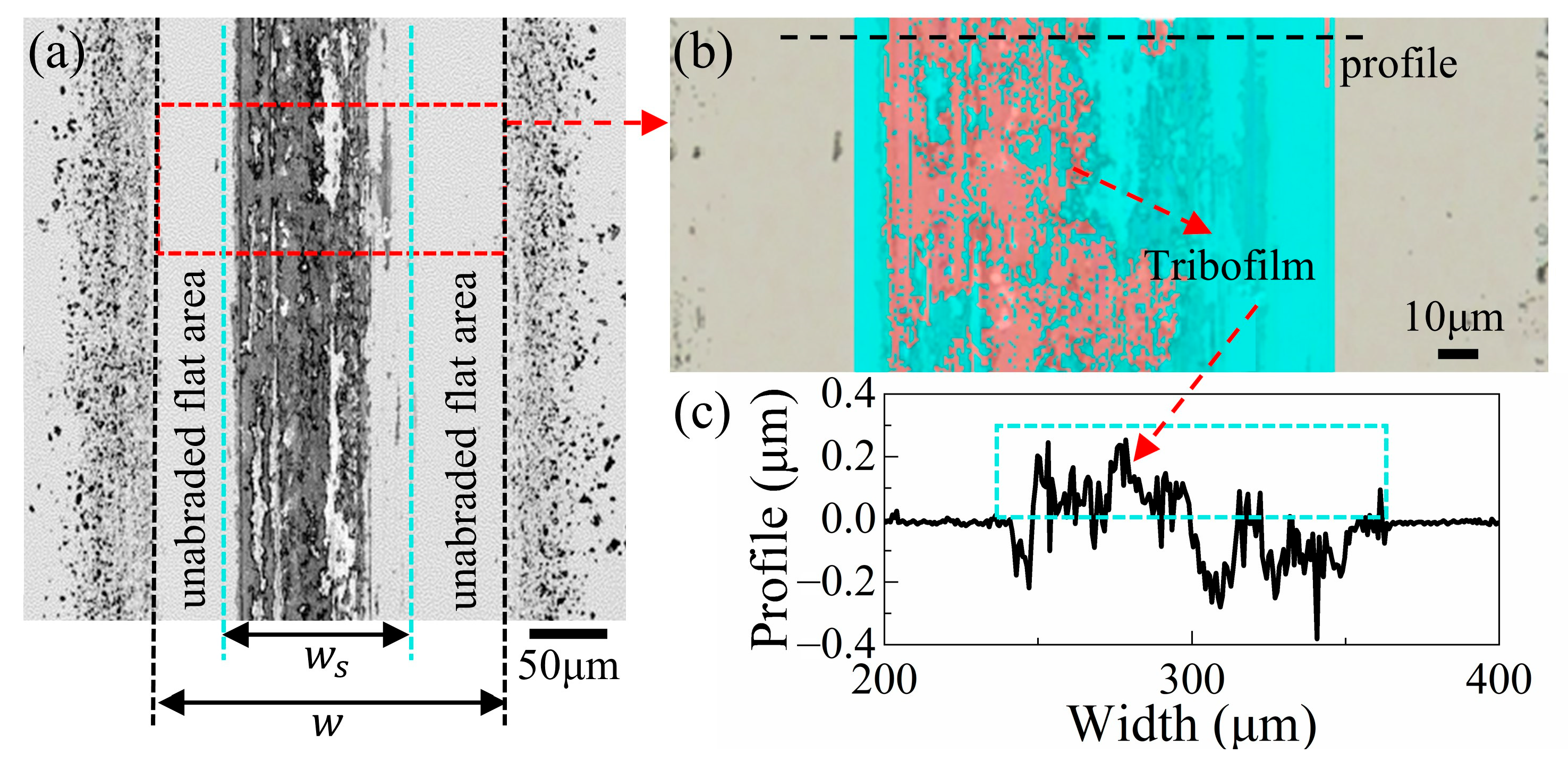
In the subsequent analysis of the experimental results, we obtained numerous images of the coating surface morphology similar to that shown in Figure 4. To quantify the experimental wear track’s characteristics, we defined the following parameters: (1) As shown in Figure 4a, the characteristic contact width is represented by w, while the scratch width is denoted by   w s . Both parameters were obtained in the VK-X250 analysis software (version 1. 1. 20. 83). There were two clean areas between the scratch track and the debris regions on both sides, which were called “unabraded flat areas”. (2) S p is the percentage of the unabraded flat areas accounting for the characteristic contact area, calculated as S p = 1 w s / w . (3) S c is the ratio of the tribofilm area (in red color) to the scratch scar area (in cyan color) in Figure 4b. (4) h c denotes the average thickness of the tribofilm. The value of h c is calculated by the formula: h c = V c / A f , where V c is the volume of the tribofilm, and A f is the cross-section areas of the tribofilm in Figure 4c.

3. Results

3.1. Friction-Reduction and Anti-Wear Performance of CBG Coating

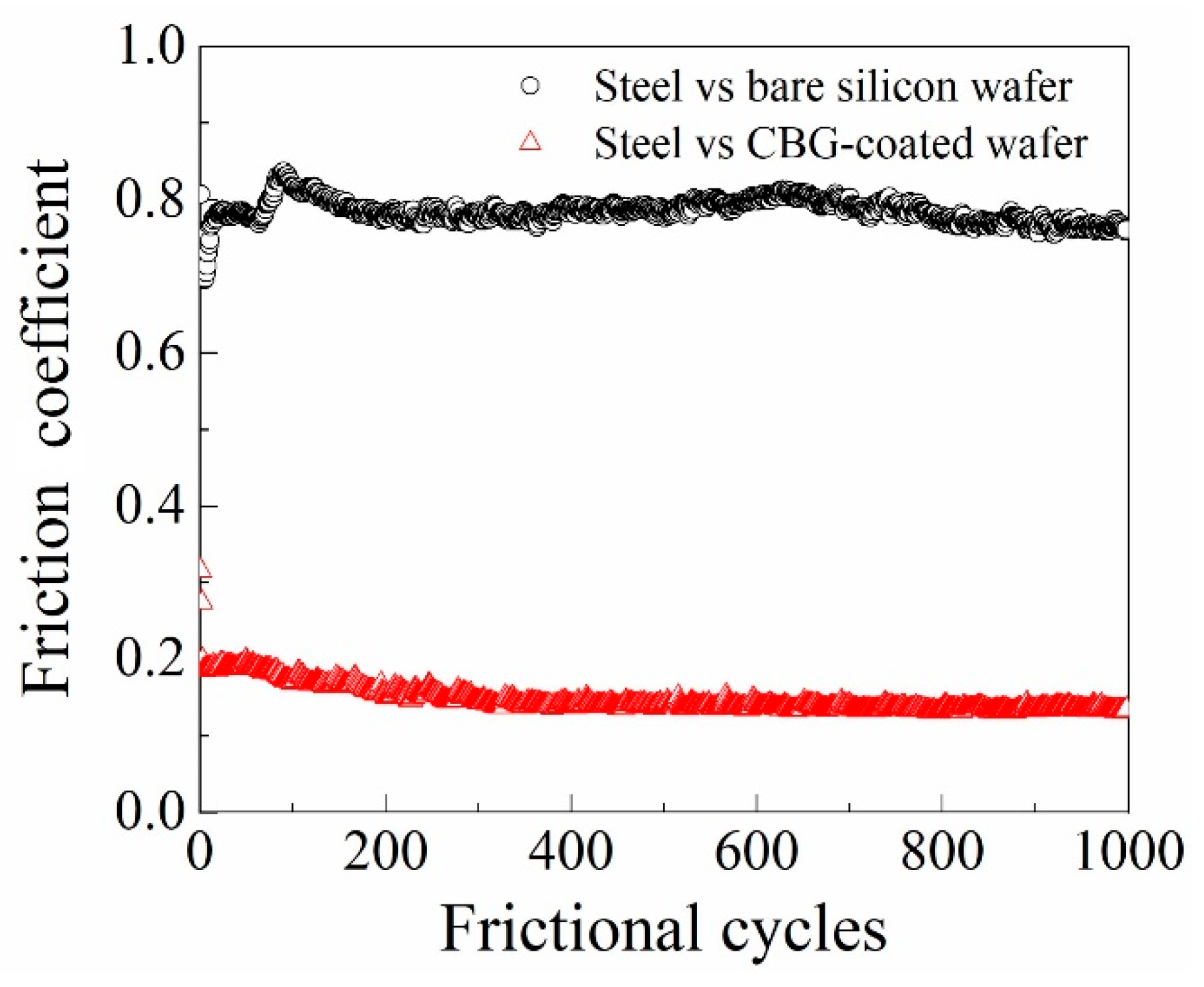
The friction-reduction effect and the anti-wear property of the CBG-coated silicon wafer were first examined under a normal load of 2 N (Hertzian maximum contact pressure ~700 MPa) and a sliding speed of 1 mm/s. The number of sliding cycles was set to 1000. For comparison, the tribological performance of the bare silicon wafer against the steel ball was also evaluated under the identical sliding conditions. In Figure 5, the friction coefficient curve of the CBG-coated samples is smoother than that of the bare sample. The steady friction coefficient of the CBG coating remained at a low level of 0.17, representing a significant reduction compared to the bare sample’s friction coefficient of 0.80. In addition, compared with other coatings (e.g., diamond-like carbon (DLC) and molybdenum disulfide (MoS2)), the friction coefficient of the CBG coating was similar or even lower [36,37,38]. As evident from the friction coefficient curves, the CBG-coated sample demonstrated superior friction-reduction performance.
The surface features of the friction pairs after tests were characterized in Figure 6. Severe wear existed on both the surface of the bare silicon wafer and its steel ball. The steel ball surface was badly damaged with craters, while severe grooves and cracks appeared on the bare silicon wafer (Figure 6a,b,e,f). Abrasive wear dominated when the steel ball slid against bare silicon. The wear width of the bare silicon wafer was about 236 μ m , and the average depth and maximum depth of the grooves were about 0.98 μ m and 2.86 μ m , respectively. The wear rates of the bare silicon wafer and steel ball were up to 6.33 × 10⁻⁵ mm3N−1m−1 and 1.70 × 10⁻⁵ mm3N−1m−1. In contrast, the scratch width of the CBG coating was about 94 μ m , and the average scratch depth was only 0.11 μ m . Consequently, the wear rates of the CBG-coated silicon wafer and steel ball were significantly reduced. In detail, the total wear rate of the CBG-coated sample was only 2.51 × 10⁻⁶ mm3N−1m−1 and the wear rate of the steel ball against the CBG coating was 2.10 × 10⁻⁷ mm3N−1m−1. In sum, the results of the comparative tests strongly supported the suggestion that the CBG coating possessed excellent friction-reduction and anti-wear capabilities.
Furthermore, Figure 6c,d,g,h showed that a large amount of graphene fragments and debris accumulated on the surfaces of the CBG coating and the steel ball. Adhesive wear dominates when steel balls slide against CBG-coated silicon wafers, in contrast to the abrasive wear observed with bare silicon. A transfer layer formed on the ball surface, while a tribofilm formed on the CBG coating surface. As shown in Figure 6c, the transfer layer consists of two parts: an elliptical contact area (red dotted line) covered by irregular-sized fragments and a new peripheral area (yellow dotted line) due to piled debris adjacent to the contact area. The boundary of the elliptical contact area was defined by a distinct indentation profile whose diameter in the direction perpendicular to the sliding movement matched the width of the wear track (Figure 6g). The formation of the peripheral area was attributed to the existence of spatial gaps between the coating and ball surface along the sliding direction [39,40]. Moreover, the diameter of the peripheral area in the direction perpendicular to the sliding movement matched the width of the flat areas, as shown in Figure 6g. So, S p can also be approximated as the ratio of the peripheral area to the transfer layer area, where the value of S p was 57.14%. The formation of the transfer layer and the tribofilm not only enhanced lubrication, but also isolated the direct contact between the friction pairs [41]. The area percentage of tribofilm S c was 36.77%, as seen in Figure 6g, and its average thickness h c was 144.9 nm, as shown in Figure 6h. As a result, the formation of the transfer layer and the tribofilm was beneficial for low friction coefficient and wear rate. In addition, the formation of the flat areas was closely associated with debris and the transfer layer [40]. Herein, we conjectured that the presence of flat areas limited the release of wear debris, contributing to the favorable tribological properties.

3.2. Load Dependence of Tribological Properties

In this section, to investigate the dependence of tribological properties, reciprocating friction tests were performed under applied loads ranging from 1 N to 5 N (equivalent maximum Hertzian contact pressures: 551–942 MPa). The pressure range was selected to simulate high-stress service conditions, facilitating the characterization of the coating’s performance under extreme stress states. The tests were performed with a sliding velocity of 1 mm/s for a total of 1000 cycles.
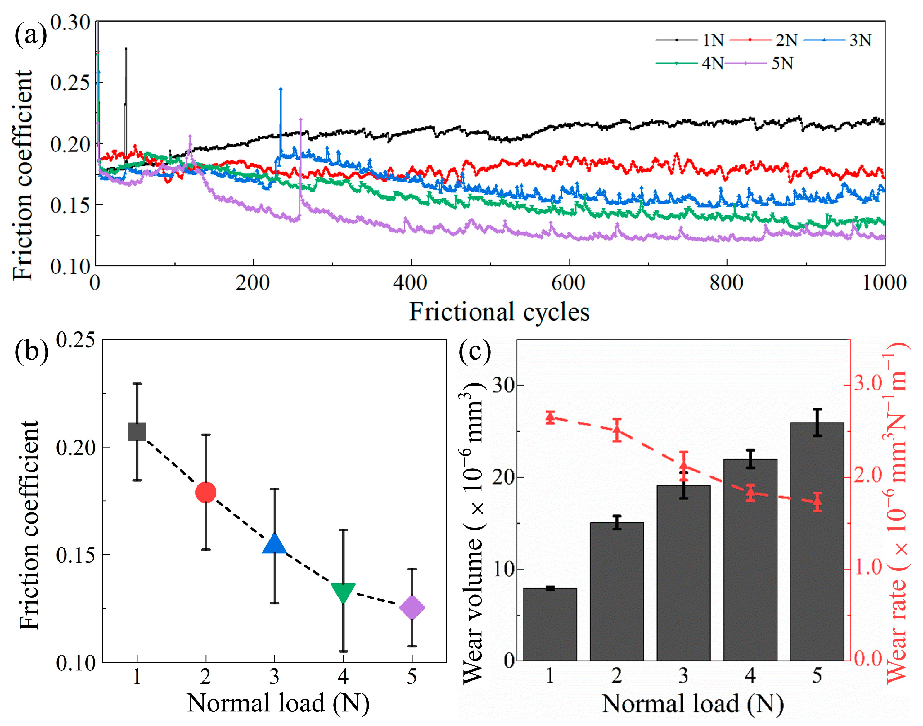
The friction coefficient curves for all samples were recorded and plotted as functions of sliding cycles, as presented in Figure 7a. The friction coefficient curves under various loads exhibited high similarity in their evolution trends. Such friction coefficient evolution is typical for coatings with relatively rough surfaces [42]. However, as the normal load increased above 3 N, more high peaks appeared on the curves, which could be the result of large-sized abrasive particles entering the sliding interface. As the applied normal load increased from 1 N to 5 N, the steady friction coefficient decreased slightly from 0.21 to 0.13 (Figure 7b). While the wear volume exhibited a significant increase from 7.97 × 10⁻⁶ mm3 to 2.60 × 10⁻⁵ mm3 as the normal load increased from 1 N to 5 N, the wear rate of the CBG coating showed an opposite trend, maintaining in the range of 2.66 × 10⁻⁶ mm3N−1m−1 to 1.73 × 10⁻⁶ mm3N−1m−1 (Figure 7c). For higher loads, the graphene layer was more easily worn, compromising its protective effect. From all results, the CBG coating protection effect was more pronounced at lower loads.
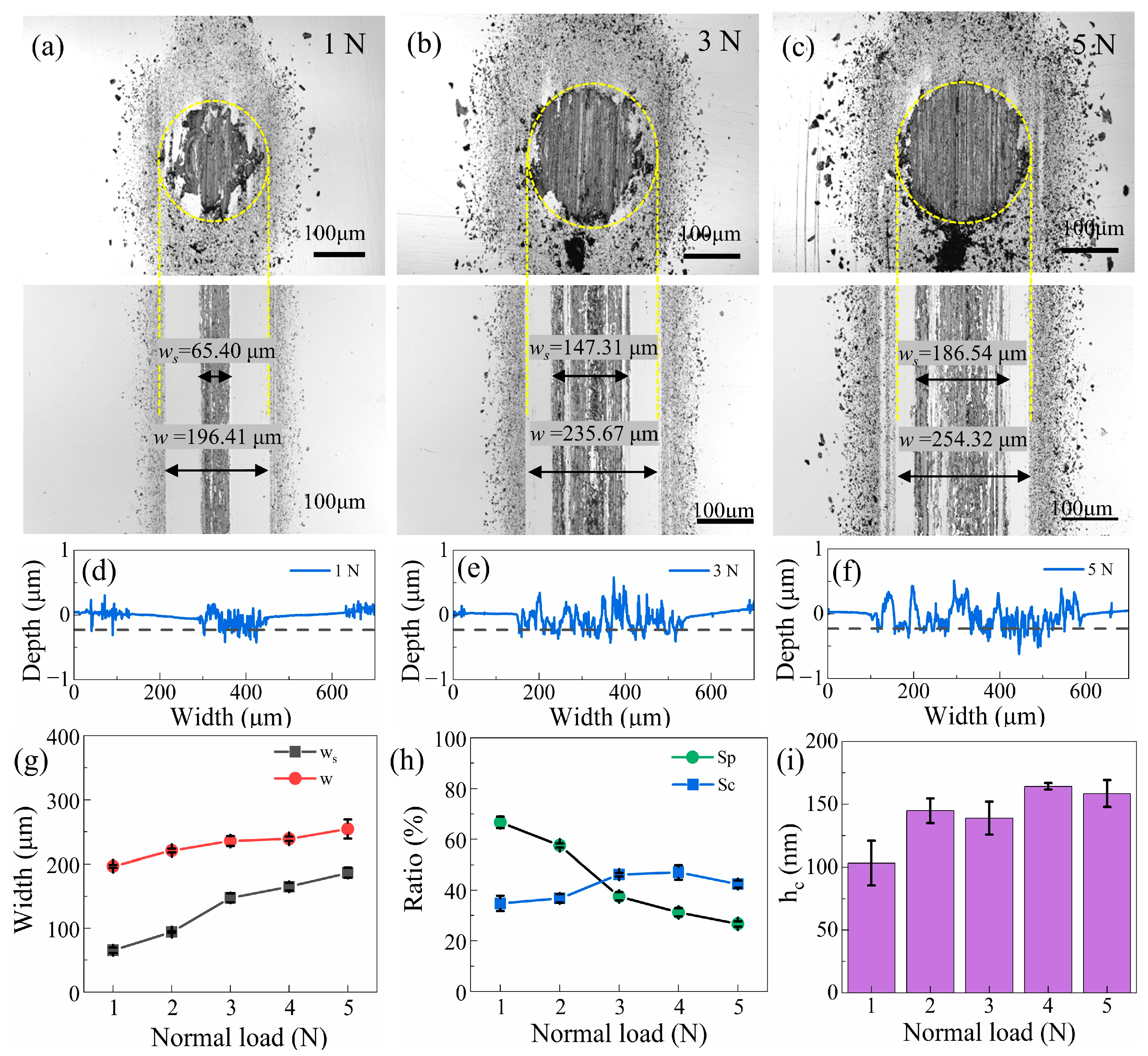
As seen from the surface morphology images after tests, the increase in scratch areas indicated severe coating wear, which can be observed in Figure 8a–f. The real scratch width increased 2.85 times from 65.40 μm at 1 N to 186.54 μm at 5 N (Figure 8a–c). The scratch profile exhibited more pronounced fluctuations and greater depth with increasing loads. Higher loads promoted severe plastic deformation and intensified abrasive wear, directly exacerbating surface damage [43]. Consequently, augmented material removal occurred with the increase in applied load, culminating in an escalation of wear volume.
An increasing trend in transfer layer formation within the scratch areas was observed as the applied load increased from 1 N to 5 N. At 1 N (low-load condition), the wear debris primarily existed as loose particles adhering to the ball surface (Figure 8a). In contrast, at 5 N, the debris formed a denser and more uniformly distributed layer (Figure 8c). This densified transfer layer expanded the effective contact area, as its growth directly governed the extent of interfacial contact [39]. The resulting increase in contact area reduced the friction coefficient by lowering the contact pressure through enhanced interfacial conformity under higher loads [44,45]. Therefore, the observed decrease in friction coefficient can be attributed to the densification of the transfer layer. Furthermore, debris compaction on the ball surface outside the scratch regions also increased with load, which may reduce frictional resistance by expanding the load-bearing area. Consequently, the friction coefficient showed a decreasing trend as the load increased.
Under loads from 1 N to 5 N, the value of S p decreased from 70% to 30% (Figure 8h), meaning the load borne by the debris increased. It can be inferred that more debris accumulated on the peripheral areas and re-entered the scratch scars as the load increased. The increase in the value of S c from 34.8% to 42.4% (Figure 8h) and the 1.53-fold increase in the average thickness h c from 103.33 nm to 158.56 nm (Figure 8i) confirmed this observation. Furthermore, only a small part of the coating was removed, with more of the coating becoming debris that was trapped inside the scratches, thereby strengthening the tribofilm. High loads promoted plastic flow of wear debris, which first filled the coating’s surface defects and microcracks, and subsequently formed a continuous protective film, and this film effectively reduced direct substrate-counterbody contact, thereby minimizing adhesive wear [43,46]. Therefore, the shrinking flat areas enhanced the self-lubrication effect of the coating by promoting a thicker and more robust tribofilm, leading to the wear rate decreasing with increasing load.

3.3. Wear Evolution and Mechanisms

To investigate the evolution of the coating wear process, a re-running experimental scheme was used since it is difficult to observe the dynamic evolution of the wear state on the interface in situ. Under the same load of 2 N, four different cycles were adopted, namely, 1000, 3000, 5000, and 8000 cycles. As such, the wear process of the CBG coating was approximately depicted by the wear states at different cycles.
The friction coefficient curves under different cycles are recorded in Figure 9a, and the mean friction coefficients are plotted against the progressive cycles in Figure 9b. It can be seen that all samples exhibited highly similar evolutions. The friction coefficient curves were smooth during the whole process, even over 8000 cycles without an abrupt change. Unlike other coatings, the CBG coating exhibits no distinct run-in period followed by a relatively stable period [40,47]. The mean friction coefficient fluctuated slightly between 0.17 and 0.19 as the number of sliding cycles increased (Figure 9b). As seen in Figure 9c, with the number of cycles increasing from 1000 to 8000, the wear volume increased from 1.51 × 10⁻⁵ mm3 to 5.04 × 10⁻⁵ mm3. However, the calculated wear rate of the CBG coating showed a decreasing pattern from 2.51 × 10⁻⁶ mm3N−1m−1 to 1.05 × 10⁻⁶ mm3N−1m−1. Moreover, after 5000 cycles, the wear volume of the CBG coating grew slowly, while the wear volume of the silicon substrate accelerated 6.2 times from 0.92 × 10⁻⁵ mm3 to 5.66 × 10⁻⁵ mm3. As a result, the coating’s protection performance was weakened.
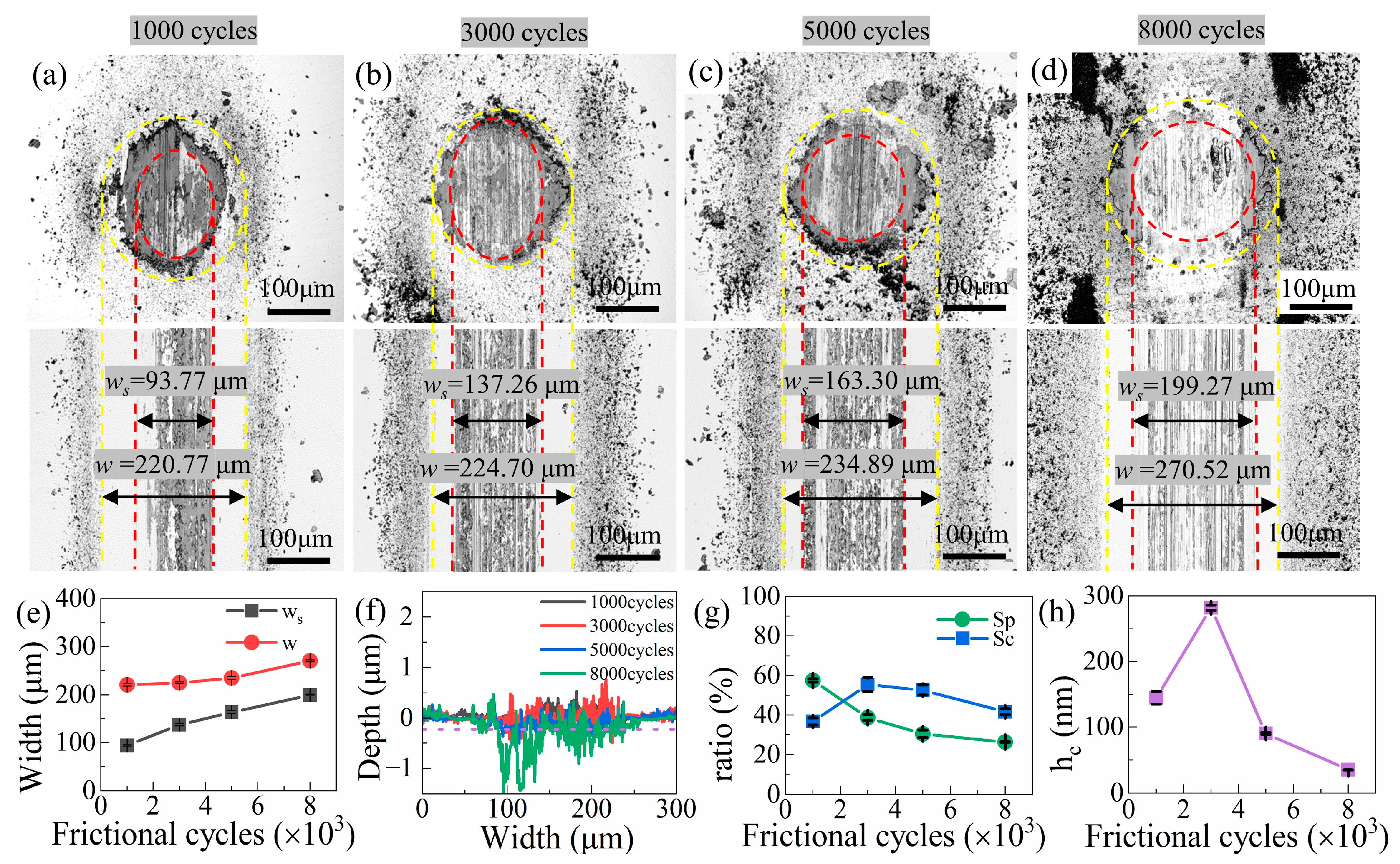
From Figure 10a–d, the widths of the scratch tracks increased from 93.77 μ m to 199.27 μ m , corresponding to a 4.52-fold expansion. As seen in Figure 10a, most of the scratch area on the transfer layer was covered by debris (highlighted by the red circles) after 1000 cycles. However, after 8000 cycles, the steel ball’s substrate was visibly exposed, and destructive pits had formed on its surface (Figure 10d). The wear became more severe with increasing number of cycles. Consistent with the scenario of identical applied loads, as the sliding cycles increased, degree of debris compaction outside the transfer layer on the steel ball (between the red and yellow circles) increased. The characteristic contact width increased from 220.77 μ m to 270.52 μ m (Figure 10e). The value of S p decreased from 57.5% to 26.3% (Figure 10g). However, unlike the continuous reduction in the friction coefficients observed under high loads, the evolution of friction coefficients during the wear process was more complex. Therefore, in addition to the increase in contact area induced by the load-bearing effect of debris, the variations in the friction coefficient were also influenced by other factors.
Figure 10f shows the 10-line-averaged profiles of the scratch tracks after different cycles. It was clear that a significant accumulation of debris filled the scratches, particularly before reaching 3000 cycles, which was confirmed by the increase in S c and h c (Figure 10g,h). The value of S c increased by 18.70% and that of h c   increased by 136.89 nm. However, the mean friction coefficient over the 1000–3000 cycles increased from 0.176 to 0.192, opposite to the decreasing trend observed in experiments under different loads. This suggested that there might have been other reasons that weakened the effect of the increase in contact area. Furthermore, from 3000 cycles to 8000 cycles, the friction coefficient decreased by 0.018, while the values of S c and h c reduced by 24.7% and 87%, respectively. Herein, we conjecture that the effect of the flat areas was not constant throughout the wear process. At the 8000-th cycle, the maximum depth of the scratches was greater than 1.0 μ m and the average depth was 0.3 μ m . (Figure 10f). At this point, the substrate was severely worn (as shown in Figure 9c). Nonetheless, the peaks of the profiles indicated that a tribofilm still existed at this stage, which might explain why the CBG coating still exhibited a protective effect at 8000-th cycle.
In order to further investigate wear evolution, we obtained SEM images of the scratch scars on the coating surface at different stages. Combining the experimental results in Figure 9 and Figure 10, we categorized the wear evolution of CBG coatings into three stages: the initial adhesive wear stage (within 1000 cycles), the abrasive wear stage (1000–5000 cycles), and the accelerated substrate wear stage (after 5000 cycles).
As shown in Figure 11a, debris, flakes, and microcracks coexisted. It was inferred that within 1000 cycles, microcracks occurred on the coating surface due to high stress. Adhesive wear led to the peeling of the coating into flakes and small loose debris. From 1000 to 3000 cycles, a large amount of loose debris agglomerated and reorganized under constant pressure, leading to the densification of the tribofilm. The value of h c confirmed this densification (Figure 10h). Densification led to an increase in the content of sp3-bonded carbon, resulting in an increase in hardness [48]. The surface state of the transfer layer was consistent with that of the tribofilm (Figure 10b). Because the re-destruction of the dense tribofilm occurred synchronously, larger flakes and debris coexisted on the surface instead of small debris at the 3000-th cycle (Figure 11b). As a result, the roughness and hardness of the contact surface resulted in an increasing trend of friction coefficient, despite the increase in real contact area. After 3000 cycles, the rough tribofilm was polished by constant pressure, dramatically reducing its thickness. Especially at the 5000th cycle, the coating surface was very smooth despite a few scratches and microcracks. The tribofilm and the transfer layer gradually formed a smooth and perfect fit, leading to the decrease in friction coefficient. Therefore, during abrasive wear, the variations in the friction coefficient was mainly determined by the state of the contact interface.
Finally, within 5000–8000 cycles, the coating damage was severe due to the inclusion of a large number of hard substrate-derived particles. The smooth tribofilm was destroyed and gradually removed, and thus obvious grooves and scratches appeared on the surface, as shown in Figure 11d. In this stage, the thickness of the tribofilm significantly decreased by 61.5%, while S c slightly decreased by 10.93%, as shown in Figure 10g,h. Notably, the coating still played a protective role because the S c value was still around 41%.
In summary, the wear mechanism of the CBG coating transitioned from adhesive wear to abrasive wear throughout the wear process. The contact state of the transfer layer and the tribofilm, as well as the modes of action of the flat areas, remarkably affected the friction coefficient. According to Equation 1, the continuous isolation of the tribofilm could be the reason why the wear rate continuously decreased over the whole evolution.

4. Discussion

4.1. The Effect of the Unabraded Flat Areas on the Coating’s Tribological Properties

In our experiments, flat areas appeared on the CBG coating and played important roles. To further verify the necessity of their existence, we designed a comparative experiment. Two groups of steel balls and CBG-coated silicon wafers were prepared. In one group, the surface of the steel balls was coated with a hydrophobic material (FC3150, Solmont Technology Inc., Wuxi, China) to inhibit debris adhesion by reducing the surface energy. This approach was based on the conclusion in Ref. [49]. The other group received no treatment. The experimental load was 2 N, with 15,000 sliding cycles and a speed of 1 mm/s. All other conditions remained consistent with the previous experiments.
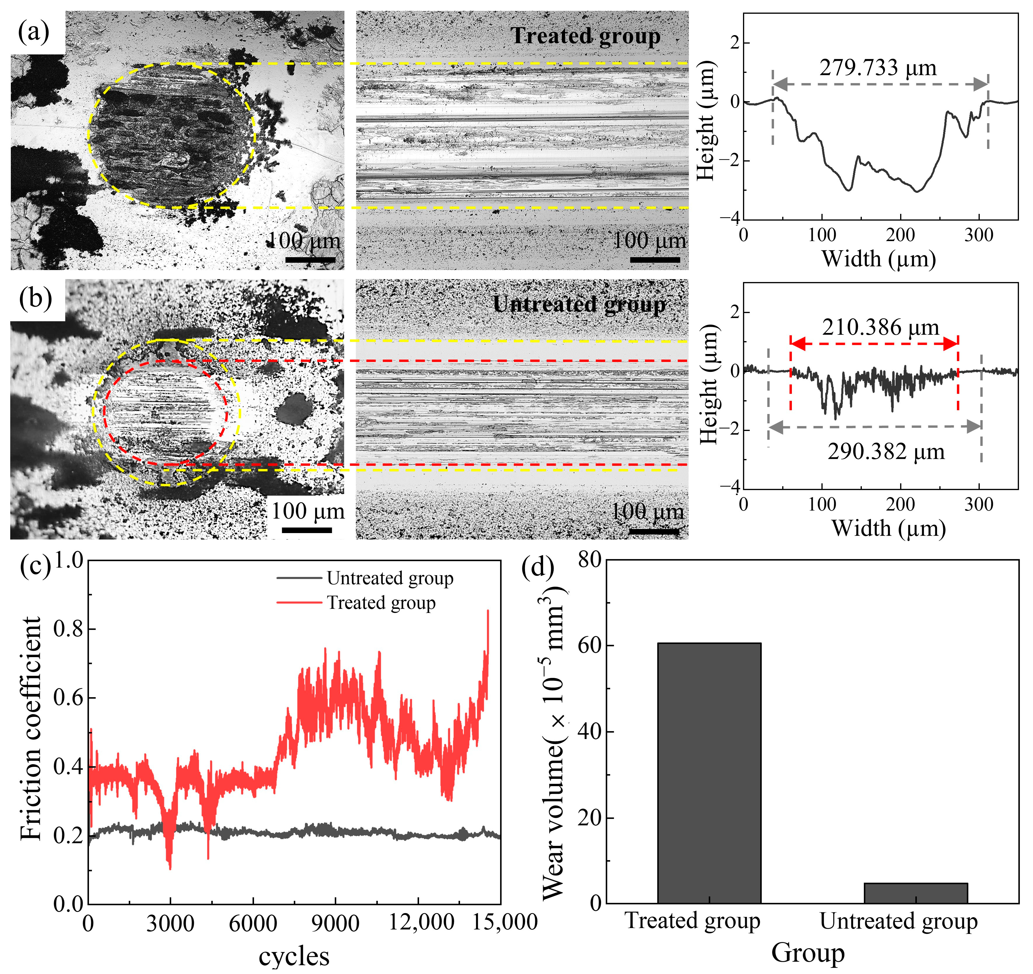
Figure 12 showed that the results of two groups exhibited significant differences. When the treated surface was used, no flat areas appeared (Figure 12a). The surfaces of the steel balls and the CBG coatings exhibited significant damage, with the wear morphology resembling the wear morphology of bare silicon (Figure 6). The scratch width reached up to 279.8 µm, while the depth exceeded 2 µm. By contrast, residual coatings remained in the untreated group (Figure 12b), consistent with previous wear results in Figure 10 and Figure 11. Scratch profile images revealed dense serrated patterns within the scratches, where plastic deformation and three-body abrasive particles coexisted [50]. Therefore, the formation of flat areas facilitated the retention of debris and strengthened the isolation effect of the tribofilm. As a result, the friction coefficient fluctuated sharply within the range of 0.4–0.8, and the coatings were eventually damaged after approximately7,500 cycles (Figure 12c), while the untreated group maintained a low friction coefficient around 0.2 consistently. The coatings’ wear volume was up to 60.55 × 10⁻⁵ mm3 in the treated group, while that of the untreated group was only 6.80 × 10⁻⁵ mm3 (Figure 12d). Therefore, the existence of flat areas enabled low friction and a long coating life.

4.2. The Role of the Unabraded Flat Areas in the Wear Process

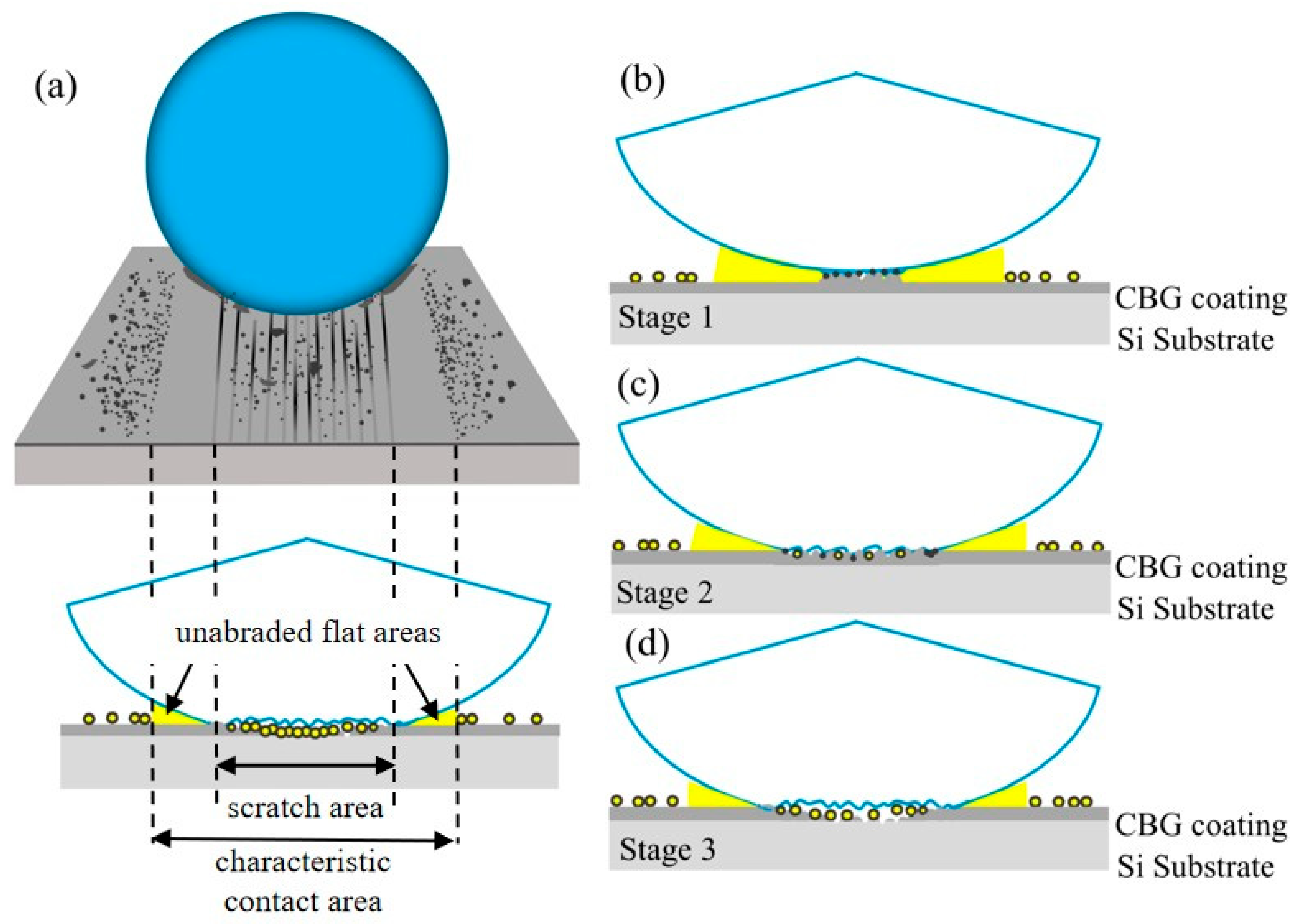
From the above experimental findings, it was confirmed that the presence of flat areas could affect the tribological properties of the CBG coating, by limiting debris removal and changing the debris behavior. On the basis of the transfer layer formation model proposed by Lofaj et al. [40], relevant discussions are made about the evolution of the flat areas and their effects on tribological behaviors. The formation of flat areas is intuitively shown in Figure 13a.
In the adhesive wear stage (Figure 13b), the flat areas are gradually formed, and this formation increases the thickness and integrity of the tribofilm (Figure 8i and Figure 10h). Unlike the simple mechanical compaction and isolation effects of three-body abrasives [51], the flat areas release the stored debris to enhance self-lubrication. Meanwhile, their synergistic effect with tribofilm and transfer layer modifies contact lubrication. Unlike the simulation results [52], which indicated that high loads lead to a high contact area ratio and thus reduced lubrication, the presence of flat areas increases the compactness of the transfer layer and enhances lubrication. Since the low friction coefficient in dry sliding conditions is generally attributed to the formation of a transfer layer [53,54], the flat areas in adhesive wear contribute to the reduction in the friction coefficient.
During the abrasive wear stage, the load-bearing effect of flat areas increases the actual contact area and distributes stress more uniformly, which directly reduces friction. Meanwhile, the smoothness of the tribofilm also decreases the friction coefficient. This explains the more significant reduction in friction coefficient. It has also been reported in tribological studies on graphene, where the expansion of the contact area contributes to friction stability [39]. During the accelerated substrate wear stage (Figure 13d), severe scratch wear shifts the load-bearing zone from scratches to flat areas (Figure 10f), increasing debris compaction (Figure 10d). The smooth surfaces of flat areas maintain low and stable friction and wear rates.
It is also important to mention that although flat areas are related to transfer layers, transfer layers alone cannot guarantee the formation of flat areas. The formation of flat areas with lubricating functionality may require specific structural conditions, such as covalent bonding between atoms or specific defect density (Figure 2). This could be a key reason for forming flat areas in CBG coatings. This study further demonstrates that flat areas represent a unique tribo-functional region: unlike interlayer lubrication of multilayer graphene coatings or random debris accumulation in transfer layers [55,56], flat areas exhibit controlled morphology and sustained load-bearing capacity. Therefore, further research is needed to explore the formation of unabraded flat areas and their intricate interplay with other aspects of the tribological system.

5. Conclusions

This study comprehensively investigated the macroscale tribological properties of the CBG coating, mainly focusing on the tribological performance demonstration, load-dependent behavior, and wear mechanisms. Main conclusions were drawn as follows:
The CBG coating on a silicon substrate demonstrated excellent friction-reduction and anti-wear capacities. Its steady friction coefficient of 0.17 was significantly lower than the bare sample’s friction coefficient of 0.80. The wear rate of the bare silicon wafer was up to 6.33 × 10⁻⁵ mm3N−1m−1, while that of the CBG-coated sample was only 2.51 × 10⁻⁶ mm3N−1m−1. These impressive performance characteristics could be attributed to the formation of protective tribofilms and transfer layers. A key finding was the identification and characterization of “unabraded flat areas” on the wear track, which proved to be a critical factor for the coatings’ excellent friction-reduction and anti-wear performance.
When the applied load increased from 1 N to 5 N, the steady friction coefficient slightly decreased from 0.21 to 0.13, and the wear rate decreased from 2.66 × 10⁻⁶ mm3N−1m−1 to 1.73 × 10⁻⁶ mm3N−1m−1. The observed friction reduction could be attributed to higher loads promoting the densification and uniform distribution of transfer layers. Furthermore, the ratio of unabraded flat areas decreased by 40% as the load increased. This decrease in the unabraded flat areas helped to limit the release of debris and enhance the self-lubrication effect, playing a key role in reduction in the wear rate.
In the re-running experiments, the mean friction coefficient slightly fluctuated between 0.17 and 0.19 over 8000 cycles, and the wear rate decreased from 2.51 × 10⁻⁶ mm3N−1m−1 to 1.05 × 10⁻⁶ mm3N−1m−1. The wear process involved three distinct stages: initial adhesive wear, abrasive wear, and accelerated substrate wear. In the initial stage, microcracks form and adhesive wear causes the peeling of the coating into flakes and debris. The abrasive stage witnessed the formation and re-destruction of dense lubrication film, leading to the observed friction fluctuations. In the final stage, the load-bearing role of the flat areas could be decisive, restricting debris escape, enhancing self-lubrication, and synergizing with tribo-layers to stabilize friction and extend coating life.
Overall, the CBG coating’s covalent-bonded structure and tribolayer dynamics enable excellent macroscale tribological behavior, suggesting broad applications in protective coatings under high-stress conditions. Future work will extend to investigating the CBG coating’s performance under industrially relevant conditions (e.g., variable speeds, temperature/humidity fluctuations) to further validate its practical applicability.

Author Contributions

Conceptualization, X.L. and J.Z.; methodology, X.Z. and L.L.; validation, J.Z.; formal analysis, X.Z.; investigation, X.Z.; resources, X.L., L.L., and K.L.; data curation, X.Z.; writing—original draft preparation, X.Z.; writing—review and editing, X.L. and J.Z.; visualization, X.Z.; supervision, X.L., J.Z. and K.L.; funding acquisition, X.L., J.Z. and K.L. All authors have read and agreed to the published version of the manuscript.

Funding

This research was funded by the National Natural Science Foundation of China (grant numbers 52375179, 52375178, and 51975174) and the Guangdong-Hong Kong-Macau Critical Optical Com-ponents Precision Manufacturing Research Center (grant numbers 20231056060001, 20221064010051).

Institutional Review Board Statement

Not applicable.

Data Availability Statement

The data presented in this study are available on request from the corresponding author.

Conflicts of Interest

The authors declare no conflicts of interest.

References

  1. Carvalho, A.F.; Kulyk, B.; Fernandes, A.J.S.; Fortunato, E.; Costa, F.M. A Review on the Applications of Graphene in Mechanical Transduction. Adv. Mater. 2021, 34, 2101326. [Google Scholar] [CrossRef]
  2. Urade, A.R.; Lahiri, I.; Suresh, K.S. Graphene Properties, Synthesis and Applications: A Review. JOM 2022, 75, 614–630. [Google Scholar] [CrossRef]
  3. Janavika, K.M.; Prakash Thangaraj, R. Graphene and its application: A review. Mater. Today Proc. 2023. [Google Scholar] [CrossRef]
  4. Berman, D.; Erdemir, A.; Sumant, A.V. Few layer graphene to reduce wear and friction on sliding steel surfaces. Carbon 2013, 54, 454–459. [Google Scholar] [CrossRef]
  5. Berman, D.; Deshmukh, S.A.; Sankaranarayanan, S.K.R.S.; Erdemir, A.; Sumant, A.V. Extraordinary Macroscale Wear Resistance of One Atom Thick Graphene Layer. Adv. Funct. Mater. 2014, 24, 6640–6646. [Google Scholar] [CrossRef]
  6. Tamuly, J.; Bhattacharjya, D.; Saikia, B.K. Graphene/Graphene Derivatives from Coal, Biomass, and Wastes: Synthesis, Energy Applications, and Perspectives. Energy Fuels 2022, 36, 12847–12874. [Google Scholar] [CrossRef]
  7. Siow, L.T.; Lee, J.R.; Ooi, E.H.; Lau, E.V. Application of graphene and graphene derivatives in cooling of photovoltaic (PV) solar panels: A review. Renew. Sustain. Energy Rev. 2024, 193, 114288. [Google Scholar] [CrossRef]
  8. Li, C.; Zheng, C.; Cao, F.; Zhang, Y.; Xia, X. The Development Trend of Graphene Derivatives. J. Electron. Mater. 2022, 51, 4107–4114. [Google Scholar] [CrossRef]
  9. Huang, W.; Yu, J.; Kwak, K.J.; Gallego-Perez, D.; Liao, W.C.; Yang, H.; Ouyang, X.; Li, L.; Lu, W.; Lafyatis, G.P.; et al. Atomic Carbide Bonding Leading to Superior Graphene Networks. Adv. Mater. 2013, 25, 4668–4672. [Google Scholar] [CrossRef]
  10. Yang, H.; Yilmaz, G.; Han, G.; Eriten, M.; Zhang, Z.; Yu, S.; Shi, M.; Yan, H.; Yang, W.; Xie, P.; et al. A quick response and tribologically durable graphene heater for rapid heat cycle molding and its applications in injection molding. Appl. Therm. Eng. 2020, 167, 114791. [Google Scholar] [CrossRef]
  11. Garman, P.D.; Johnson, J.M.; Talesara, V.; Yang, H.; Du, X.; Pan, J.; Zhang, D.; Yu, J.; Cabrera, E.; Yen, Y.C.; et al. Dual Silicon Oxycarbide Accelerated Growth of Well-Ordered Graphitic Networks for Electronic and Thermal Applications. Adv. Mater. Technol. 2019, 4, 1800324. [Google Scholar] [CrossRef]
  12. Xie, P.; Yang, H.; Zhao, Y.; Yu, W.; Cheng, L.; Yang, W.; Yan, H.; Tan, J. Carbide-bonded graphene coating of mold insert for rapid thermal cycling in injection molding. Appl. Therm. Eng. 2017, 122, 19–26. [Google Scholar] [CrossRef]
  13. Liu, X.; Zhang, L.; Zhou, W.; Zhou, T.; Yu, J.; Lee, L.J.; Yi, A.Y. Fabrication of Plano-Concave Plastic Lens by Novel Injection Molding Using Carbide-Bonded Graphene-Coated Silica Molds. J. Manuf. Sci. Eng. 2019, 141, 081011. [Google Scholar] [CrossRef]
  14. Li, L.; Yang, G.; Lee, W.B.; Ng, M.C.; Chan, K.L. Carbide-bonded graphene-based Joule heating for embossing fine microstructures on optical glass. Appl. Surf. Sci. 2020, 500, 144004. [Google Scholar] [CrossRef]
  15. Cabrera, E.D.; Zhang, P.; Liao, W.C.; Yen, Y.C.; Yu, J.; Castro, J.; Lee, L.J. Graphene coating assisted injection molding of ultra-thin thermoplastics. Phys. Eng. Sci. Med. 2015, 55, 1374–1381. [Google Scholar] [CrossRef]
  16. Yang, G.; Li, L.; Lee, W.B.; Ng, M.C.; Chan, C.Y. Investigation of the heating behavior of carbide-bonded graphene coated silicon wafer used for hot embossing. Appl. Surf. Sci. 2018, 435, 130–140. [Google Scholar] [CrossRef]
  17. Garman, P.D.; Yang, H.; Yen, Y.C.; Yu, J.; Kwak, K.J.; Malkoc, V.; Talesara, V.V.; Lee, L.J.; Lu, W. SiOC-Accelerated Graphene Grown on SiO2/Si with Tunable Electronic Properties. Phys. Status Solidi (RRL)–Rapid Res. Lett. 2019, 13, 1900017. [Google Scholar] [CrossRef]
  18. Zhou, J.; He, P.; Yu, J.; Lee, L.J.; Shen, L.; Yi, A.Y. Investigation on the friction coefficient between graphene-coated silicon and glass using barrel compression test. J. Vac. Sci. Technol. B 2015, 33, 031213. [Google Scholar] [CrossRef]
  19. Berman, D.; Erdemir, A.; Sumant, A.V. Reduced wear and friction enabled by graphene layers on sliding steel surfaces in dry nitrogen. Carbon 2013, 59, 167–175. [Google Scholar] [CrossRef]
  20. Bhowmick, S.; Banerji, A.; Alpas, A.T. Friction reduction mechanisms in multilayer graphene sliding against hydrogenated diamond-like carbon. Carbon 2016, 109, 795–804. [Google Scholar] [CrossRef]
  21. Wang, D.; Li, F.; Huang, Q.; Wang, F.; Liu, B.; Zhao, Y. Effect of normal load on the tribological behavior of graphene coating under current-carrying state. J. Mech. Sci. Technol. 2024, 38, 6193–6203. [Google Scholar] [CrossRef]
  22. Toosinezhad, A.; Alinezhadfar, M.; Mahdavi, S. Tribological behavior of cobalt/graphene composite coatings. Ceram. Int. 2020, 46, 16886–16894. [Google Scholar] [CrossRef]
  23. Johnson, K.L. Adhesion and friction between a smooth elastic spherical asperity and a plane surface. Proc. R. Soc. Lond. Ser. A 1997, 453, 163–179. [Google Scholar] [CrossRef]
  24. Yang, X.; Li, C.; Ye, Z.; Zhang, X.; Zheng, M.; Gu, J.; Jiang, J. Effects of tribo-film on wear resistance of additive manufactured cobalt-based alloys during the sliding process. Surf. Coat. Technol. 2021, 427, 127784. [Google Scholar] [CrossRef]
  25. Liang, S.; Shen, Z.; Yi, M.; Liu, L.; Zhang, X.; Ma, S. In-situ exfoliated graphene for high-performance water-based lubricants. Carbon 2016, 96, 1181–1190. [Google Scholar] [CrossRef]
  26. Wu, P.; Li, X.; Zhang, C.; Chen, X.; Lin, S.; Sun, H.; Lin, C.-T.; Zhu, H.; Luo, J. Self-Assembled Graphene Film as Low Friction Solid Lubricant in Macroscale Contact. ACS Appl. Mater. Interfaces 2017, 9, 21554–21562. [Google Scholar] [CrossRef]
  27. Hu, Z.; Fan, X.; Diao, D. Facilitation of sp2 nanocrystallites on the formation of transfer films for stable low friction with in-situ TEM nanofriction study. Tribol. Int. 2022, 174, 107713. [Google Scholar] [CrossRef]
  28. Wahl, K.J.; Chromik, R.R.; Lee, G.Y. Quantitative in situ measurement of transfer film thickness by a Newton’s rings method. Wear 2008, 264, 731–736. [Google Scholar] [CrossRef]
  29. Li, L.; Zhou, J. Evaluation of Warpage and Residual Stress of Precision Glass Micro-Optics Heated by Carbide-Bonded Graphene Coating in Hot Embossing Process. Nanomaterials 2021, 11, 363. [Google Scholar] [CrossRef]
  30. Xu, J.; Kawaguchi, M.; Kato, T. Evolution of transfer layers on steel balls sliding against hydrogenated amorphous carbon coatings in ambient air. Tribol. Int. 2014, 70, 42–51. [Google Scholar] [CrossRef]
  31. Zhu, G.; Zhu, W.; Lou, Y.; Ma, J.; Yao, W.; Zong, R.; Zhu, Y. Encapsulate α-MnO2 nanofiber within graphene layer to tune surface electronic structure for efficient ozone decomposition. Nat. Commun. 2021, 12, 4152. [Google Scholar] [CrossRef]
  32. Lee, A.Y.; Yang, K.; Anh, N.D.; Park, C.; Lee, S.M.; Lee, T.G.; Jeong, M.S. Raman study of D* band in graphene oxide and its correlation with reduction. Appl. Surf. Sci. 2021, 536, 147990. [Google Scholar] [CrossRef]
  33. Silva, D.L.; Campos, J.L.E.; Fernandes, T.F.D.; Rocha, J.N.; Machado, L.R.P.; Soares, E.M.; Miquita, D.R.; Miranda, H.; Rabelo, C.; Vilela Neto, O.P.; et al. Raman spectroscopy analysis of number of layers in mass-produced graphene flakes. Carbon 2020, 161, 181–189. [Google Scholar] [CrossRef]
  34. Alaferdov, A.V.; Savu, R.; Fantini, C.; Cançado, L.G.; Moshkalev, S.A. Raman spectra of multilayer graphene under high temperatures. J. Phys. Condens. Matter 2020, 32, 385704. [Google Scholar] [CrossRef]
  35. Ji, Z.; Lin, Q.; Huang, Z.; Chen, S.; Gong, P.; Sun, Z.; Shen, B. Enhanced lubricity of CVD diamond films by in-situ synthetization of top-layered graphene sheets. Carbon 2021, 184, 680–688. [Google Scholar] [CrossRef]
  36. Yu, G.; Qian, Q.; Li, D.; Zhang, Z.; Ren, K.; Gong, Z.; Zhang, J. The pivotal role of oxygen in establishing superlow friction by inducing the in situ formation of a robust MoS2 transfer film. J. Colloid Interface Sci. 2021, 594, 824–835. [Google Scholar] [CrossRef]
  37. Qi, S.; Wei, X.; Chen, L.; Geng, Z.; Luo, J.; Lu, Z.; Zhang, G. 3D graphene/hexagonal boron nitride composite nanomaterials synergistically reduce the friction and wear of Steel-DLC contacts. Nano Sel. 2021, 2, 791–801. [Google Scholar] [CrossRef]
  38. Bai, M.; Yang, L.; Li, J.; Luo, L.; Sun, S.; Inkson, B. Mechanical and tribological properties of Si and W doped diamond like carbon (DLC) under dry reciprocating sliding conditions. Wear 2021, 484–485, 204046. [Google Scholar] [CrossRef]
  39. Lofaj, F.; Tanaka, H.; Bureš, R.; Kabátová, M.; Sawae, Y. Tribochemistry of Transfer Layer Evolution during Friction in HiPIMS W-C and W-C:H Coatings in Humid Oxidizing and Dry Inert Atmospheres. Coatings 2022, 12, 493. [Google Scholar] [CrossRef]
  40. Lofaj, F.; Kabátová, M.; Bureš, R. Transfer layer evolution during friction in HIPIMS W–C coatings. Wear 2021, 486–487, 204123. [Google Scholar] [CrossRef]
  41. Shi, X.; Liskiewicz, T.W.; Beake, B.D.; Chen, J.; Wang, C. Tribological performance of graphite-like carbon films with varied thickness. Tribol. Int. 2020, 149, 105586. [Google Scholar] [CrossRef]
  42. Chen, S.; Shen, B.; Sun, F. The influence of normal load on the tribological performance of electrophoretic deposition prepared graphene coating on micro-crystalline diamond surface. Diam. Relat. Mater. 2017, 76, 50–57. [Google Scholar] [CrossRef]
  43. Şenel, M.C.; Üstün, M. Dry Sliding Wear and Friction Behavior of Graphene/ZrO2 Binary Nanoparticles Reinforced Aluminum Hybrid Composites. Arab. J. Sci. Eng. 2022, 47, 9253–9269. [Google Scholar] [CrossRef]
  44. Zhang, H.; Qu, J.; Guo, Z.; Huang, L.; Xie, Q. Negative area-dependent nanoscale friction of annular graphene sheets. AIP Adv. 2022, 12, 115312. [Google Scholar] [CrossRef]
  45. Cai, S.; Guo, P.; Zuo, X.; Zhang, D.; Zhi, L.; Ke, P.; Wang, A. Effect of Load on Tribological Behavior of MoS2/C Composite Films. Tribology 2018, 38, 51–58. [Google Scholar] [CrossRef]
  46. Korkmaz, M.E.; Gupta, M.K.; Singh, G.; Kuntoğlu, M.; Patange, A.; Demirsoz, R.; Ross, N.S.; Prasad, B. Machine learning models for online detection of wear and friction behaviour of biomedical graded stainless steel 316L under lubricating conditions. Int. J. Adv. Manuf. Technol. 2023, 128, 2671–2688. [Google Scholar] [CrossRef]
  47. Kim, M.-G.; Lee, K.-R.; Eun, K.Y. Tribological behavior of silicon-incorporated diamond-like carbon films. Surf. Coat. Technol. 1999, 112, 204–209. [Google Scholar] [CrossRef]
  48. Gong, M.; Li, H.; Wu, M.; Lv, P. Investigation of the Microstructure and Properties of Cage-Shaped Hollow Cathode Bias Voltage Modulated Si-Doped DLC Thick Film. Coatings 2025, 15, 930. [Google Scholar] [CrossRef]
  49. Polymer Engineering and ScienceEstrada-Martínez, J.; Reyes-Gasga, J.; García-García, R.; Vargas-Becerril, N.; Zapata-Torres, M.G.; Gallardo-Rivas, N.V.; Mendoza-Martínez, A.M.; Paramo-García, U. Wettability modification of the AISI 304 and 316 stainless steel and glass surfaces by titanium oxide and titanium nitride coating. Surf. Coat. Technol. 2017, 330, 61–70. [Google Scholar] [CrossRef]
  50. Frérot, L.; Pastewka, L. Elastic Shakedown and Roughness Evolution in Repeated Elastic–Plastic Contact. Tribol. Lett. 2024, 72, 23. [Google Scholar] [CrossRef]
  51. Bouillanne, O.; Mollon, G.; Saulot, A.; Descartes, S.; Serres, N.; Chassaing, G.; Demmou, K. Wear in Progress: How Third Body Flow Controls Surface Damage. Tribol. Lett. 2024, 72, 84. [Google Scholar] [CrossRef]
  52. Zhao, J.; Sheng, W.; Li, Z.; Zhang, H.; Zhu, R. Modeling and analysis of sliding wear based on fractal surface reconstruction in line contact mixed lubrication. Proc. Inst. Mech. Eng. Part J J. Eng. Tribol. 2022, 236, 135065012210777. [Google Scholar] [CrossRef]
  53. Liu, Y.; Wang, L.; Xiao, C. The synergistic mechanism between transfer layer and surface passivation of diamond-like carbon film under different gas pressure environments. Appl. Surf. Sci. 2022, 587, 152874. [Google Scholar] [CrossRef]
  54. Xu, R.; Liu, Y.; Cheng, Q.; Wang, Z.; Ma, K.; Ke, P.; Deng, Y. The synergistic mechanism of transition layer and transfer layer on dry sliding wear of multi-layered diamond-like carbon (DLC) coating at wide temperature. Diam. Relat. Mater. 2024, 141, 110589. [Google Scholar] [CrossRef]
  55. Amaral, I.R.; Forestier, A.; Piednoir, A.; Galafassi, R.; Bousige, C.; Machon, D.; Pierre-Louis, O.; Alencar, R.S.; Souza Filho, A.G.; San-Miguel, A. Delamination of multilayer graphene stacks from its substrate through wrinkle formation under high pressures. Carbon 2021, 185, 242–251. [Google Scholar] [CrossRef]
  56. Fuadi, Z.; Adachi, K. Properties of tribofilm formed on self-mated stainless steel lubricated by palm methyl ester mixed petroleum diesel fuel. Lubr. Sci. 2021, 33, 347–357. [Google Scholar] [CrossRef]
Figure 1. Characterization of the CBG coating: (a) AFM image of bare silicon surface, (b) AFM image of CBG coating surface, (c) HRTEM image of the cross-section of the CBG coating silicon surface, (d) magnified image of a selected region in (c) for presenting the structure of the CBG coating.
Carbon 11 00072 g001
Figure 2. Chemical composition and structure characterizations of CBG coating: (a) overall XPS spectrum analysis, (b) C1s spectrum, (c) Si2p spectrum, and (d) Raman analysis.
Carbon 11 00072 g002
Figure 3. (a) Structure components of the reciprocating linear tribometer and (b) friction pair.
Carbon 11 00072 g003
Figure 4. Schematic diagram of parameter definition: (a) a typical CBG coating surface after test, (b) magnified comparison image of the tribofilm in the scratch shown in (a), and (c) the cross-sectional profile along the line in (b).
Carbon 11 00072 g004
Figure 5. Friction coefficient with and without CBG coating.
Carbon 11 00072 g005
Figure 6. Results of comparison tests: (a,b) laser microscope image and profile of the steel ball against bare silicon wafer, (c,d) laser microscope image and profile of the steel ball against the CBG-coated silicon wafer, (e,f) laser microscope image and profile of the bare silicon wafer, (g,h) laser microscope image and profile of the CBG coating (The gray dashed line is the CBG coating-substrate interface in Figure (h).).
Carbon 11 00072 g006
Figure 7. Tribological properties of CBG coating under different loads: (a) friction coefficient with cycles, (b) steady friction coefficient versus load, (c) wear volume and wear rate of CBG coating versus load.
Carbon 11 00072 g007
Figure 8. Laser microscope images of CBG coating and steel ball under different loads, and results of quantitative parameters against normal load: (ac) wear morphologies of CBG coatings and steel ball surfaces, (df) scratch profile curves (Gray dashed lines are the CBG coating-substrate interface.), (g) the real scratch width and the characteristic contact with values versus load, (h) the percentage of the flat areas accounting for the nominal total contact area S p , and the ratio of the tribofilm area to the scratch scar area S c , (i) the average thickness of the tribofilm h c .
Carbon 11 00072 g008
Figure 9. Tribological properties under different cycles: (a) variation in friction coefficient curves, (b) mean value of friction coefficient, (c) results of wear volume and wear rate.
Carbon 11 00072 g009
Figure 10. Wear morphologies at different stages and results of quantitative parameters against frictional cycles: (ad) laser microscope images of the steel balls and coatings at different stages, (e) the real scratch width w s and the characteristic contact with w, (f) scratch profile curves, (g) the percentage of the unabraded polished areas S p , and the ratio of the tribofilm area S c , (h) the average thickness of the tribofilm h c .
Carbon 11 00072 g010
Figure 11. SEM images of tribofilm at different stages: (a) 1000 cycles, (b) 3000 cycles, (c) 5000 cycles, (d) 8000 cycles.
Carbon 11 00072 g011
Figure 12. Results of the comparative experiment: (a,b) wear morphologies of CBG coatings and steel ball surfaces, and scratch profile curves, (c) comparison of the friction coefficient curve, (d) comparison of the coating’s wear volume.
Carbon 11 00072 g012
Figure 13. Interface contact state at different stages: (a) top and front views of friction pairs contact, (b) initial adhesive wear stage, (c) abrasive wear stage, (d) substrate accelerated wear stage.
Carbon 11 00072 g013
Disclaimer/Publisher’s Note: The statements, opinions and data contained in all publications are solely those of the individual author(s) and contributor(s) and not of MDPI and/or the editor(s). MDPI and/or the editor(s) disclaim responsibility for any injury to people or property resulting from any ideas, methods, instructions or products referred to in the content.