Article

NMR Spectroelectrochemistry in Studies of Procarbazine Oxidation by Laser-Induced Graphene Thin Films

1
Hainan Engineering Research Center of Tropical Ocean Advanced Optoelectronic Functional Materials, Hainan International Joint Research Center of Marine Advanced Photoelectric Functional Materials, Key Laboratory of Laser Technology and Optoelectronic Functional Materials of Hainan Province, Key Laboratory of Functional Materials and Photoelectrochemistry of Haikou, College of Chemistry and Chemical Engineering, Hainan Normal University, Haikou 571158, China
2
School of Electronic Science and Engineering, Xiamen University, Xiamen 361100, China
*
Authors to whom correspondence should be addressed.
Submission received: 28 April 2025 / Revised: 8 July 2025 / Accepted: 17 July 2025 / Published: 21 July 2025
(This article belongs to the Section Carbon Materials and Carbon Allotropes)

Abstract

In this paper, nanoscale graphene film electrodes were prepared using laser-induced technology, and an in situ electrochemical cell was constructed. The normalized peak areas at 2.82 ppm for the samples without the in situ electrochemical cell and with an in situ electrochemical cell are 4.02 and 4.41, respectively. Tests showed that this in situ electrochemical cell has minimal interference from the nuclear magnetic resonance (NMR) magnetic field, allowing for high-resolution in situ spectra. Using this in situ electrochemical cell and employing in situ electrochemistry combined with NMR techniques, we investigated the oxidation reaction of 0.01 M procarbazine (PCZ) in real-time. We elucidated the following oxidation mechanism for procarbazine: the oxidation of PCZ first generates azo-procarbazine, which then undergoes a double bond shift to hydrazo-procarbazine. hydrazo-procarbazine undergoes hydrolysis to yield benzaldehyde-procarbazine, and then finally oxidizes to produce N-isopropylterephthalic acid. This confirms that the combination of in situ electrochemistry and nuclear magnetic resonance technology provides chemists with an effective tool for in situ studying the reaction mechanisms of drug molecules.

Graphical Abstract

1. Introduction

The standalone electrochemical technique can obtain macroscopic kinetic and thermodynamic processes of catalytic dynamics on the electrode surface and the adsorption of reactive molecules at the solid–liquid interface by adjusting the energy levels applied to the electrodes. However, it cannot directly reveal the microscopic processes of the reactions. The NMR technique can reveal microscopic changes in the molecular structure of substances, for example, changes in chemical shift and slight splitting caused by the coupling of different atomic nuclei in the sample. Therefore, the combination of in situ electrochemistry (EC) and NMR technology allows for real-time, non-destructive tracking of material reaction processes at the molecular level, uncovering unstable intermediates and revealing reaction mechanisms [1,2,3,4]. However, in the EC-NMR technology, EC and NMR have mutual interference, such as the magnetic susceptibility of the electrode, conductivity, excessive generation of EC products, and the formation of precipitates during the reaction, which can cause inhomogeneity in the magnetic field. This, in turn, results in issues such as decreased magnetic field resolution and signal-to-noise ratio sensitivity [5]. Conversely, the weakening of magnetic field uniformity will also affect the electrochemical characteristics of the EC cell. Therefore, addressing the issue of interference between NMR and EC is a key challenge in the field of EC-NMR technology.
The early form of the EC-NMR combined device was a flow electrochemical cell. Richards et al. [6] were the first to design a flow in situ EC-NMR device, where, driven by a pump, the solution after the reaction moves from the site of the electrochemical reaction to the RF region of the NMR spectrometer for detection. However, an issue arose due to the large volume of the reaction cell, resulting in excessively long sampling times. Utilizing the principle of skin depth, when the metal coating film is very thin, can reduce the influence of the electrode material on the NMR magnetic field. Mincey et al. [7] proposed an in situ EC device using a metal coating as the working electrode (WE). Webster et al. [8] created an electrode with a gold film thickness of less than 10 nm, which had a negligible effect on the magnetic field and successfully explored the reduction reaction mechanism of halogenated aromatics. To avoid interference from metal electrodes with radio frequency signals, ultrafine carbon fibers that do not produce paramagnetic signals were introduced into in situ electrochemical battery electrodes by Klod et al. [9] to construct an in situ electrochemical device. Bussy et al. [10] further utilized carbon fibers to design a more simplified electrochemical cell, which features a wide electrochemical potential window suitable for most modern NMR spectrometers and can analyze different elements. Huang et al. improved the carbon fiber electrochemical cell by loading black platinum and platinum–ruthenium black onto the carbon fibers as WE. To minimize the impact on NMR, all three electrodes were placed above the NMR radio frequency region. They used this setup to track the dynamic reaction process of ethanol oxidation [11,12]. Zhang et al. [13] prepared a nanoscale polyaniline thin film electrode using an electrochemical deposition method and constructed an in situ device to systematically investigate the effect of solvents on the oxidation reaction mechanisms of substances. Wang et al. [14] developed a platinum/molybdenum disulfide/graphene nanoplatelet electrode and established an in situ device to explore the mechanism of ethanol oxidation reactions. Pollyana et al. [15] constructed an in situ device to create electrodes by mixing graphite powder with epoxy resin, achieving high-resolution real-time monitoring of the dynamic processes of substance redox reactions.
As one of the two-dimensional nanomaterials, graphene is hailed as the “king of new materials” in the 21st century [16] due to its large specific surface area, high carrier mobility, excellent electrochemical properties, and high biocompatibility [17,18]. Laser-induced graphene (LIG) was first proposed by James M. Tour [19], and the resulting graphene structure exhibits a unique porous network structure [20]. This material can be applied in fields such as supercapacitors, microfluidic devices, sensors, and electrocatalysis. The laser-induced technique is safe, non-toxic, stable, easily controllable, and can directly achieve etching [21] and patterning. Due to its outstanding conductivity, high flexibility, large specific surface area, and good chemical stability [22,23], LIG has become an ideal electrode material. The 3D porous laser-induced graphene composite electrode prepared by the Kritsada research group [24] is used for the detection of curcumin, demonstrating excellent electron transfer capability and good electrocatalytic performance. Procarbazine is an anticancer drug and one of the most commonly used chemotherapeutic agents for the treatment of Hodgkin’s lymphoma [25]. Studying the electrochemical reaction mechanisms of PCZ through in situ EC-NMR technology aids in analyzing the pharmacokinetic characteristics of PCZ in patients with Hodgkin’s lymphoma. In this paper, we synthesized graphene electrodes using laser-induced technology to construct an in situ EC cell. In this EC cell, we placed the LIG film electrode only within the NMR monitoring area, minimizing the influence of EC on the NMR. This enables the high-resolution in situ spectral collection of the dynamic reaction process of PCZ and aids in deducing its oxidation reaction mechanism.

2. Materials and Methods

2.1. Chemicals

Procarbazine hydrochloride, potassium chloride, heavy water (containing TMS), and concentrated hydrochloric acid, all of which are analytically pure grade, were purchased from China National Pharmaceutical Group Chemical Reagent Co., Ltd. (Shanghai China). The pH of the Procarbazine Hydrochloride aqueous solution is adjusted using concentrated hydrochloric acid. Indium tin oxide (ITO) conductive glass was purchased from China Yingkou shangsheng trading Co., Ltd. (Yingkou China). The polyimide (PI) adhesive was obtained from China Jinlong Insulation Materials Co., Ltd. (Changzhou China).

2.2. Preparation of LIG Thin Film as the WE

We used a laser-induced technique to prepare LIG/ITO electrodes under pre-optimized experimental conditions [26]: First, 0.08 g of polyimide (PI) glue was weighed and uniformly coated onto an ITO surface sized 10 mm × 3 mm × 1.1 mm. Then, it was heated at 100 °C for 30 min in a vacuum drying oven, followed by curing at 166 °C for 10 min in an oven. The cured PI glue was transformed into graphene via direct laser engraving, with the laser power set to 2.2 W (i.e., 40% attenuation of 5.5 W output power) and the engraving depth set to 30 mm2/min.

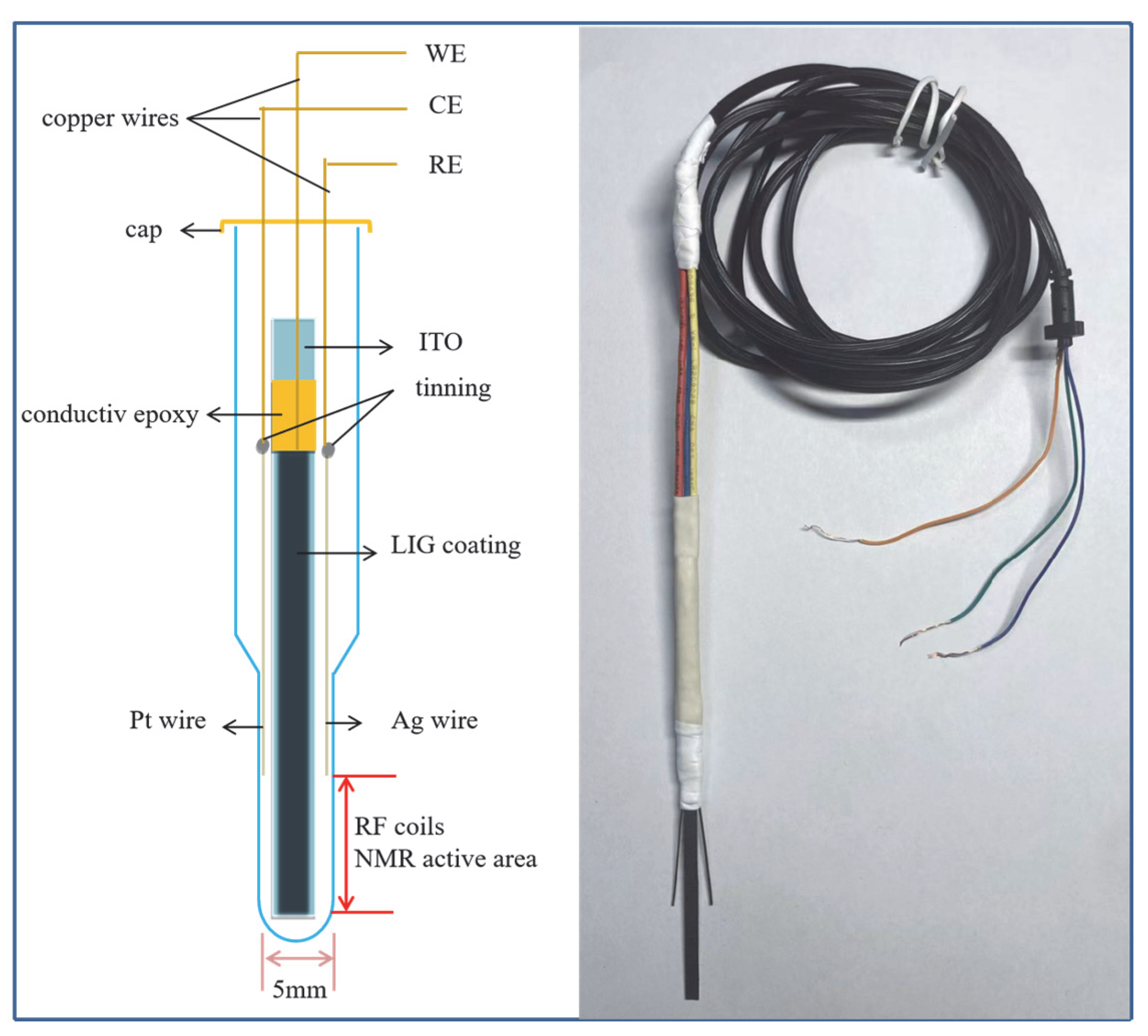
2.3. Construction of In Situ Electrochemical Cells

The in situ EC cell we designed uses LIG/ITO as the WE, a platinum wire with a diameter of 0.5 mm as the counter electrode (CE), and a silver wire also with a diameter of 0.5 mm as the reference electrode (RE). This three-electrode system is placed inside a specially designed NMR tube, as shown in Figure 1. The entire three-electrode assembly is secured with a PTFE membrane, and only the WE is located within the RF detection area of the NMR spectrometer. The electrodes are connected via copper wires wrapped in PTFE heat shrink tubing. The ends of the copper wires are connected to the electrochemical workstation with electrical wires.

2.4. Measurements

The electrochemical tests were conducted using a CHI660E electrochemical workstation purchased from Chenhua Co., Ltd. (Shanghai, China). The Nano pro III laser direct writing instrument was obtained from Tianjin Jiayin Nano Technology Co., Ltd. (Tianjin, China). The 1D 1H NMR spectra were collected using a Varian 500 MHz NMR spectrometer (Agilent Technologies, Santa Clara, CA, USA) equipped with a 5 mm probe, employing a standard one-dimensional pulse sequence. The spectral width is set to 10 ppm, with a duration of 2 s for each spectral scan, and both the settling time and sampling time are 1 s. The reference material used for calibration is tetramethylsilane, and the experimental temperature is 25 °C. The microscopic structure of the electrodes is analyzed using a Hitachi S-4800 scanning electron microscope from Japan (Tokyo, Japan).
Figure 1. Electrochemical cell designed for in situ EC-NMR.
Carbon 11 00052 g001

3. Results and Discussion

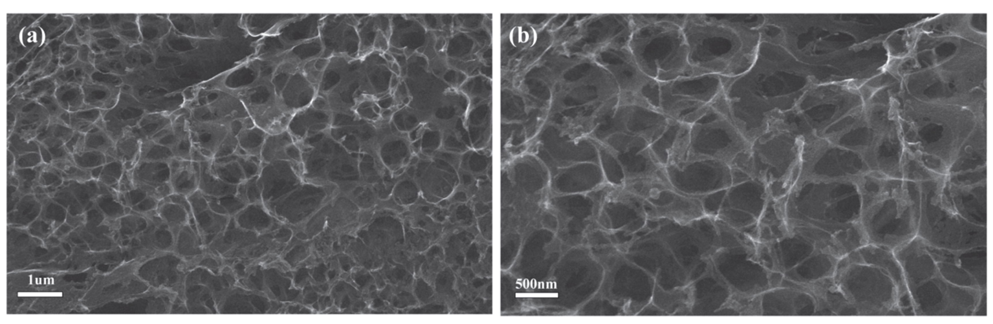
3.1. The Characterization of LIG

We used scanning electron microscopy (SEM) to characterize the surface morphology of the laser-induced graphene (LIG). Figure 2 displays the image of the LIG/ITO electrode, with Figure 2b providing an enlarged view of Figure 2a. From Figure 2, it can be observed that the laser-induced graphene membrane exhibits a porous, net-like structure, composed of interwoven few-layer graphene nanosheets. This structure endows the LIG with a high specific surface area, providing more active sites for electrochemical oxidation-reduction reactions. As a result, it demonstrates excellent electrochemical performance, enabling faster charge transfer at the electrode and thereby enhancing the overall catalytic efficiency.
Figure 3 shows the Raman spectrum (a) and XPS spectrum (b) of LIG. In Figure 3a, three typical peaks of graphene can be observed: the D peak at 1333 cm−1, the G peak at 1573 cm −1 (which is caused by the in-plane vibrations of sp2 carbon atoms), and the 2D peak at 2646 cm−1, confirming the successful fabrication of graphene. From the XPS spectrum of LIG (Figure 3b), the presence of C1s, N1s, and O1s diffraction peaks indicates that a small amount of N and O is present in the graphene structure when LIG is produced in an atmospheric environment. Additionally, the high intensity signal of the D peak further confirms the existence of disorder and co-doping of N and O in the fabricated LIG.

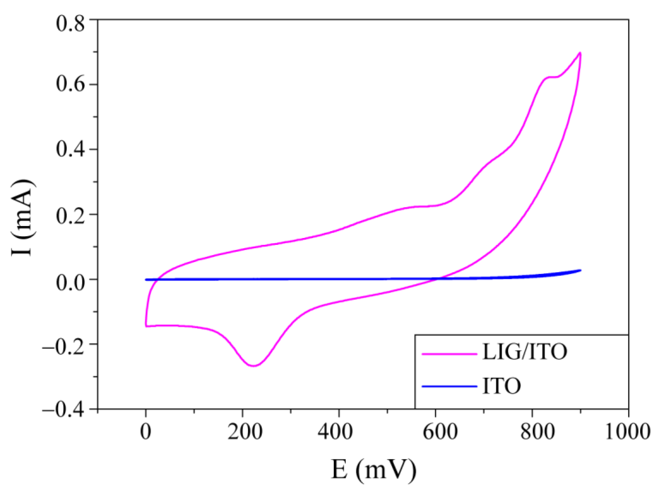
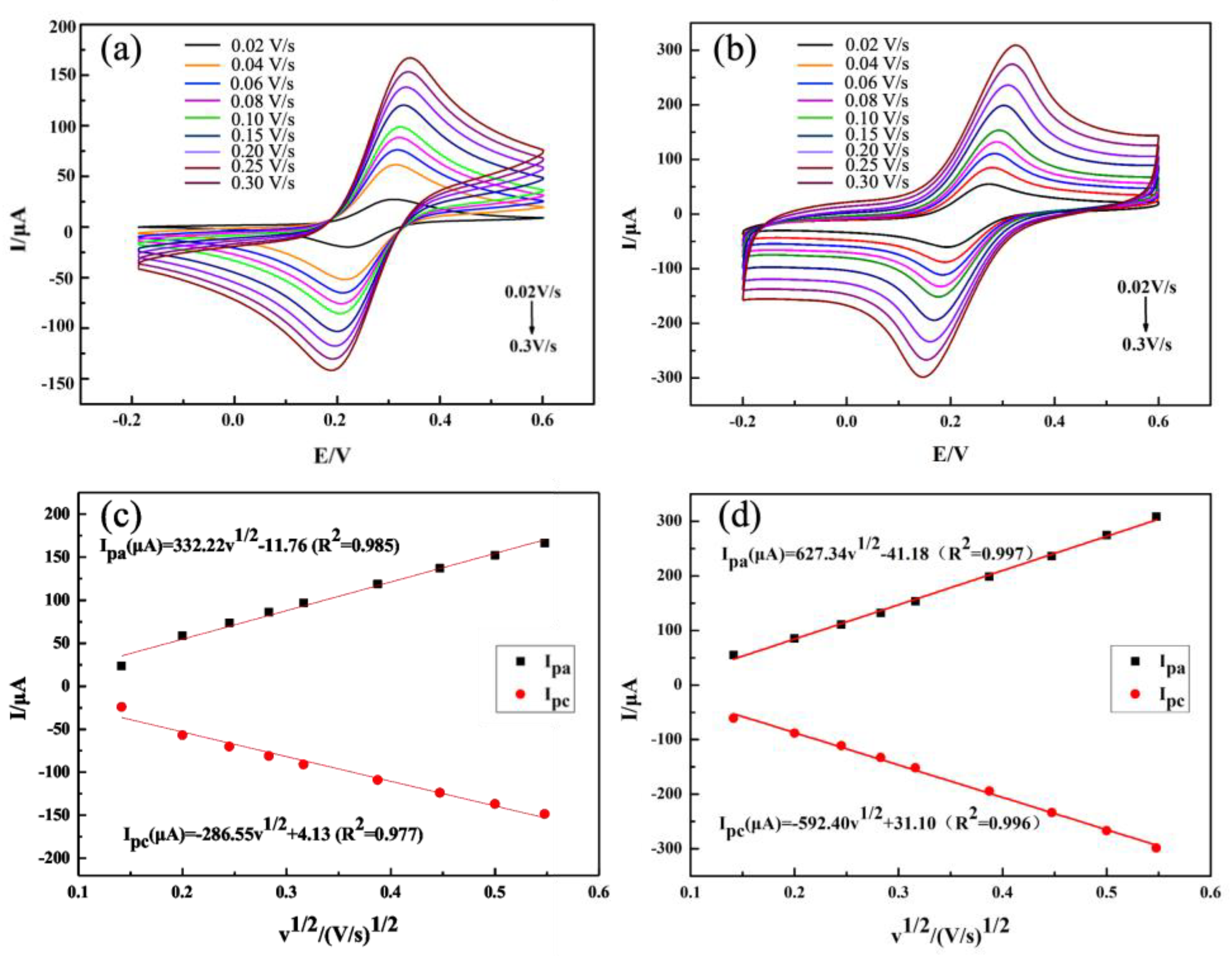
3.2. The Electrocatalytic Behavior of PCZ

To investigate the EC properties of PCZ on LIG/ITO electrodes and ITO electrodes, cyclic voltammograms (CV) were obtained in a 0.01 M PCZ aqueous solution at a pH of 2 (Figure 4). We noticed that the current intensity of the LIG/ITO electrode is significantly higher than that of the ITO electrode, indicating that the LIG/ITO electrode exhibits superior catalytic performance for PCZ. Additionally, in a solution with a pH of 2, the oxidation peak potential of PCZ is 820 mV; therefore, the subsequent in situ experiments were conducted at a voltage of 820 mV.
To verify the increase in the electrochemical active surface area (ECSA) of LIG, CV tests were conducted on ITO electrodes and LIG/ITO electrodes at different scan rates in a 1.0 mM [Fe(CN)6]3−/4− solution containing 1.0 M KCl, as shown in Figure 5. From Figure 5c,d, it can be observed that the obtained redox peak current exhibits a linear relationship with the square root of the scan rate. According to the Randles–Sevcik equation [27]: Ip = 2.69 Í105 n3/2 A C D1/2 v1/2, where Ip is the anodic peak current (μA), n is the number of electrons transferred (in the [Fe(CN)6]3−/4− solution, n = 1), A is the electroactive surface area (cm2), C is the concentration (the concentration of [Fe(CN)6]3−/4− is 1.0 × 10⁶ mol/cm3), ν is the scan rate (mV/s), and D is the diffusion coefficient (the diffusion coefficient of [Fe(CN)6]3−/4− is 6.7 × 10⁻⁶ cm2/s). Calculations indicate that the effective area of the LIG/ITO electrode is 0.85 cm2, greater than the 0.45 cm2 of the ITO electrode, demonstrating that the electroactive surface area of LIG/ITO has increased. This proves that LIG enhances charge transfer capability and exhibits strong catalytic performance.

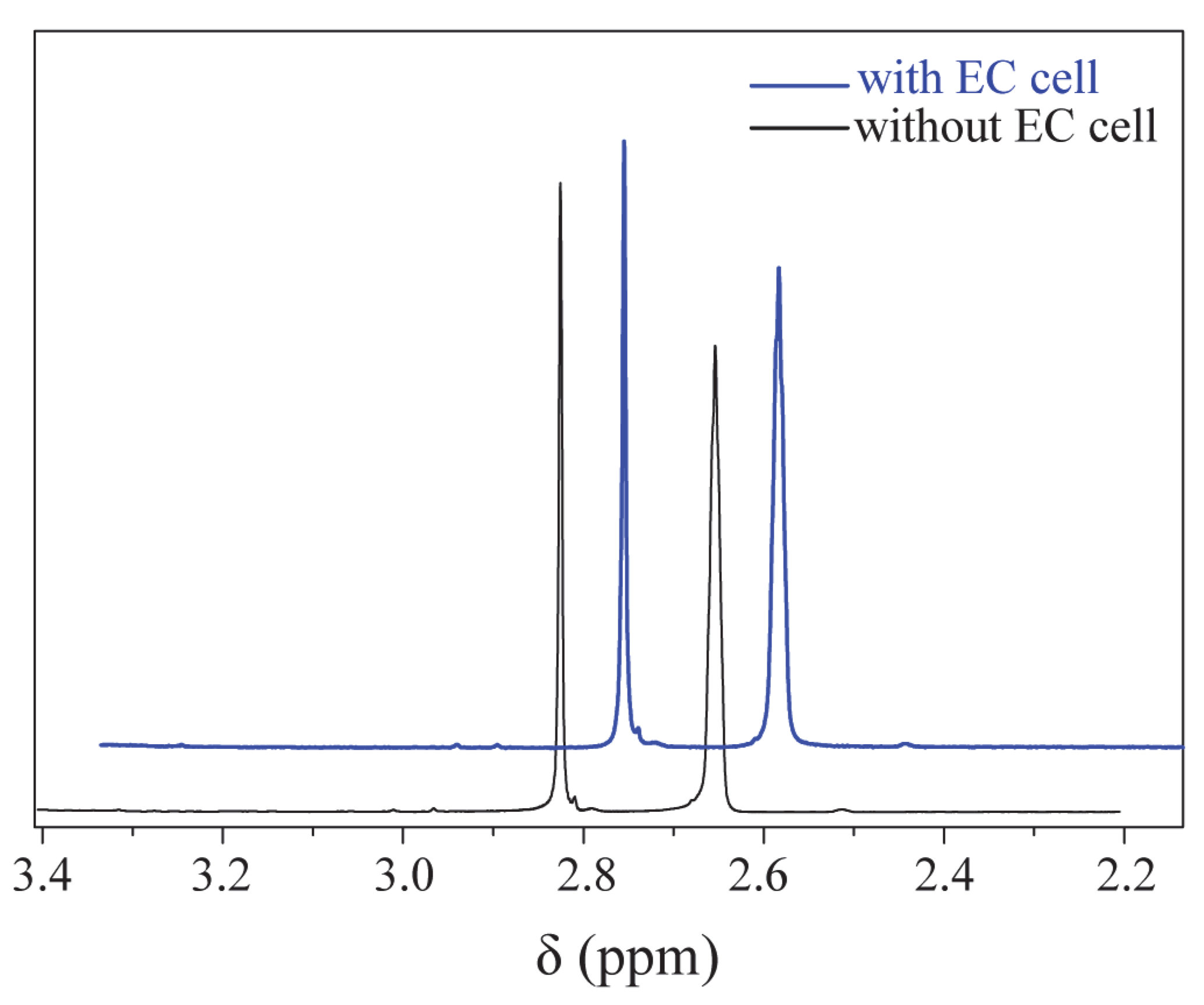
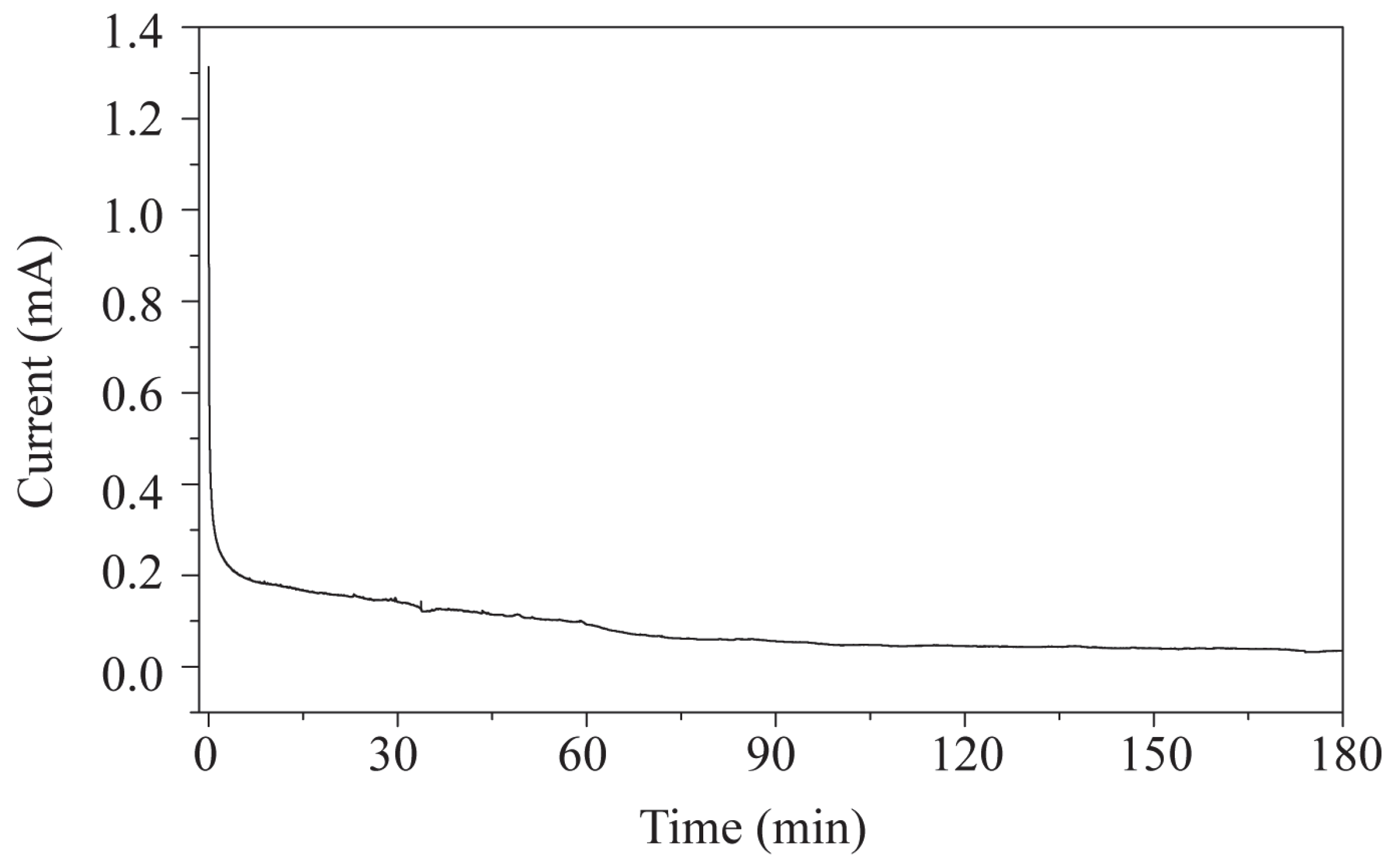
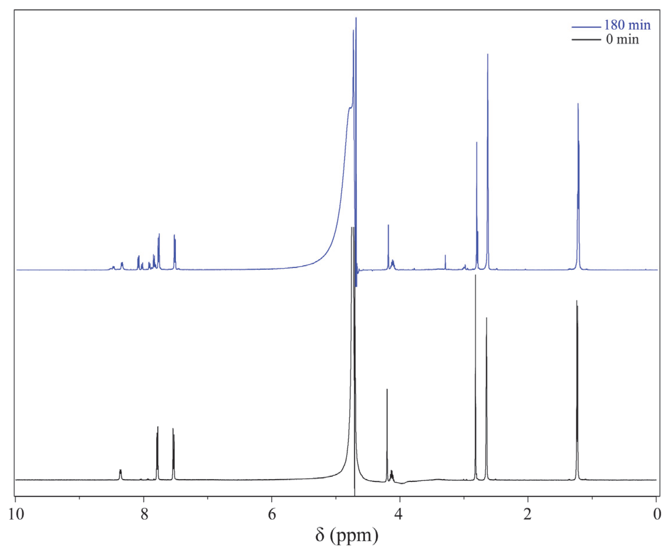
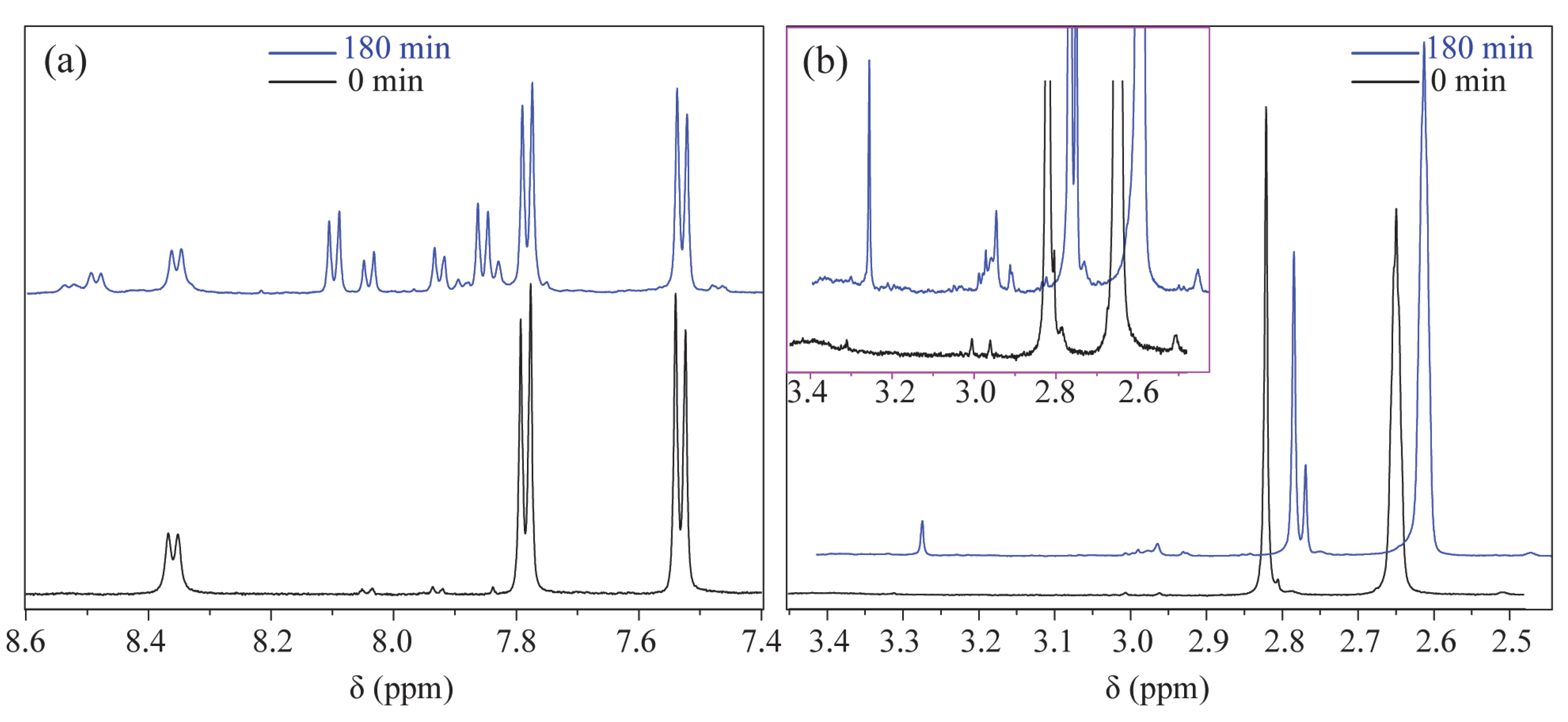
3.3. In Situ EC-NMR Experiment of PCZ Oxidation Reaction

First, to verify that the EC device has a minimal effect on the magnetic field, LIG/ITO was used as the WE, and 50 µL of pH = 2 PCZ aqueous solution was injected into the in situ EC cell for testing. As a contrast, a 50 µL pH = 2 PCZ (0.01 M) aqueous solution was also injected into a standard 5 mm NMR tube for testing. The obtained spectrum is shown in Figure 6. The normalized peak areas at 2.82 ppm for the samples without EC and with EC are 4.02 and 4.41, respectively. The results indicate that the presence or absence of the EC pool has a minimal effect on the spectra, suggesting that the LIG/ITO electrode has a very limited impact on the uniformity and resolution of the magnetic field. To investigate the electrochemical oxidation reaction of PCZ (0.01 M, pH = 2), an in situ EC-NMR combined technique was employed to monitor the dynamic reaction process of PCZ. Figure 7 shows the chronoamperometric current–time curve of PCZ at 820 mV with a LIG/ITO electrode as the WE, with a reaction time of 180 min. Figure 8a,b shows the in situ 1H NMR spectra of the PCZ at 820 mV with the LIG/ITO electrode as the working electrode. In the in situ experiments, we observed that the water peak at 4.8 ppm is quite pronounced, so we employed solvent peak suppression techniques to minimize the solvent’s interference with the in situ spectra. In Figure 8, we removed the parts affected by solvent peaks and only displayed the spectra with local changes. Additionally, the vertical scales of Figure 8a,b are different. To observe the in situ EC-NMR spectra more clearly after 180 min, we extracted the in situ EC electrode, immediately took a sample, and further enlarged the spectra, as shown in Figure 9 and Figure 10, with Figure 10 being a magnified view of Figure 9. Based on previous literature [25] and the in situ spectra, we inferred the reaction mechanism of PCZ, as illustrated in Scheme 1. From Figure 8a,b, it can be observed that the peaks at 7.54 ppm and 7.79 ppm are associated with the hydrogen atoms on the phenyl ring of PCZ, while the peak at 2.84 ppm corresponds to PCZ Ha. The heights of these signals decrease over time, which may be due to the formation of C=N in product 2, leading to a reduction in the peak for the reactant PCZ Ha. Conversely, the peak heights around 8.0 ppm (as shown in the blue slanted frames in Figure 8a) and 8.5 ppm gradually increase over time, possibly due to the formation of phenyl-CHO and phenyl-COOH after the oxidation of PCZ (as shown in products 3 and 4 of Scheme 1), as well as the movement of the hydrogen spectral peaks on the benzene ring. Regarding the increase in peak heights at 2.82 ppm, 3.0 ppm, and 3.32 ppm (as shown in the blue slanted frames in Figure 8b), it may result from the formation of double bonds in products 1 and 2, as well as the migration from N=N to N=C. From Figure 9 and Figure 10, we can observe more clearly the changes in the spectra before and after 180 min of the reaction, which is consistent with the trend observed in Figure 8. In summary, we propose that the oxidation reaction mechanism of PCZ is as follows: PCZ oxidation first produces Product 1 (azo-procarbazine), which then undergoes a double bond rearrangement to form Product 2 (hydrazo-procarbazine); Product 2 further hydrolyzes to generate Product 3 (benzaldehyde-procarbazine), which is ultimately oxidized to form Product 4 (N-isopropylterephthalic acid). So, through in situ EC-NMR experiments, we can clearly observe the dynamic process of material changes, thus providing a basis for chemists to infer the reaction mechanism of the substances.

4. Conclusions

To sum up, LIG/ITO electrodes were prepared using laser-induced techniques for the construction of an in situ electrochemical cell. In this in situ device, only the LIG/ITO electrode is placed in the radio frequency area of NMR. Experimental results show that the influence of the NMR magnetic field is extremely minimal, allowing for the acquisition of high-resolution in situ spectral data. We investigated the electrochemical oxidation reaction of PCZ in an aqueous solution with a pH of 2 using in situ EC-NMR techniques. Based on the dynamic in situ NMR spectra, we elucidated the oxidation mechanism of PCZ. The successful execution of this experiment lays a foundation for chemists to explore the redox mechanisms of substances.

Author Contributions

Conceptualization, X.Z. and Z.W.; methodology, X.Z.; software, Z.W.; validation, L.Y. and S.X.; formal analysis, Y.W. and L.W.; investigation, A.M.; resources, X.Z.; data curation, Z.W.; writing—original draft preparation, X.Z. and Z.W.; writing—review and editing, W.S.; visualization, X.Z.; supervision, W.S.; project administration, X.Z.; funding acquisition, X.Z. All authors have read and agreed to the published version of the manuscript.

Funding

This research was funded by National Natural Science Foundation of China, grant number 22462007; and National Natural Science Foundation of China, grant number 22102043.

Data Availability Statement

The original contributions presented in the study are included in the article; further inquiries can be directed to the corresponding author.

Conflicts of Interest

The authors declare no conflicts of interest.

References

  1. Jiang, Y.; Zhao, M.; Peng, Z.; Zhong, G. Progress in in-situ electrochemical nuclear magnetic resonance for battery research. Magn. Reson. Lett. 2024, 4, 13–21. [Google Scholar] [CrossRef]
  2. Simon, H.; Melles, D.; Jacquoilleot, S.; Sanderson, P.; Zazzeroni, R.; Karst, U. Combination of electrochemistry and nuclear magnetic resonance spectroscopy for metabolism studies. Anal. Chem. 2012, 84, 8777–8782. [Google Scholar] [CrossRef] [PubMed]
  3. Vyalikh, A.; Wolfram, M.; Juan-Jesús, V. Detection of electrocatalytical and -chemical processes by means of in situ flow NMR spectroscopy. Electrochem. Commun. 2024, 163, 107736. [Google Scholar] [CrossRef]
  4. Dragancea, D.; Talmaci, N.; Shova, S.; Novitchi, G.; Darvasiova, D.; Rapta, P.; Breza, M.; Galanski, M.S.; Kožıšek, J.; Arion, V.B. Vanadium(V)complexes with substituted 1,5-bis(2-hydroxybenzaldehyde)carbohydrazones and their use as catalyst precursors in oxidation of cyclohexane. Inorg. Chem. 2016, 55, 9187–9203. [Google Scholar] [CrossRef] [PubMed]
  5. Ugo, B.; Mohammed, B. Review of advances in coupling electrochemistry and liquid state NMR. Talanta 2015, 136, 155–160. [Google Scholar] [CrossRef] [PubMed]
  6. Richards, J.A.; Evans, D.H. Flow cell for electrolysis within the probe of a nuclear magnetic resonance spectrometer. Anal. Chem. 1975, 47, 964–966. [Google Scholar] [CrossRef]
  7. Mincey, D.W.; Popovich, M.J.; Faustino, P.J.; Hurst, M.M.; Caruso, J.A. Monitoring of electrochemical reactions by nuclear magnetic resonance spectrometry. Anal. Chem. 1990, 62, 1197–1200. [Google Scholar] [CrossRef]
  8. Webster, R.D. In situ electrochemical-NMR spectroscopy. Reduction of aromatic halides. Anal. Chem. 2004, 76, 1603–1610. [Google Scholar] [CrossRef] [PubMed]
  9. Klod, S.; Ziegs, F.; Dunsch, L. In situ NMR spectroelectrochemistry of higher sensitivity by large scale electrodes. Anal. Chem. 2009, 81, 10262–10267. [Google Scholar] [CrossRef] [PubMed]
  10. Bussy, U.; Giraudeau, P.; Tea, I.; Boujtita, M. Understanding the degradation of electrochemically generated reactive drug metabolites by quantitative NMR. Talanta 2013, 116, 554–558. [Google Scholar] [CrossRef] [PubMed]
  11. Huang, L.; Sorte, E.G.; Sun, S.G.; Tong, Y.Y.J. A straightforward implementation of in situ solution electrochemical 13C NMR spectroscopy for studying reactions on commercial electrocatalysts: Ethanol oxidation. Chem. Commun. 2015, 51, 8086–8088. [Google Scholar] [CrossRef] [PubMed]
  12. Huang, L.; Sun, J.-Y.; Cao, S.-H.; Zhan, M.; Ni, Z.-R.; Sun, H.-J.; Chen, Z.; Zhou, Z.-Y.; Sorte, E.G.; Tong, Y.J.; et al. Combined EC-NMR and in situ FTIR spectroscopic studies of glycerol electrooxidation on Pt/C, PtRu/C, and PtRh/C. ACS Catal. 2016, 6, 7686–7695. [Google Scholar] [CrossRef]
  13. Zhang, X.-P.; Jiang, W.-L.; Cao, S.-H.; Sun, H.-J.; You, X.-Q.; Wang, J.-L.; Zhao, C.-S.; Wang, X.; Chen, Z.; Sun, S.-G. NMR spectroelectrochemistry in studies of hydroquinone oxidation by polyaniline thin films. Electrochim. Acta 2018, 273, 300–306. [Google Scholar] [CrossRef]
  14. Wang, J.; You, X.; Xiao, C.; Zhang, X.; Cai, S.; Jiang, W.; Guo, S.; Cao, S.; Chen, Z. Small-sized Pt nanoparticles supported on hybrid structures of MoS2 nanoflowers/graphene nanosheets: Highly active composite catalyst toward efficient ethanol oxidation reaction studied by in situ electrochemical NMR spectroscopy. Appl. Catal. B Environ. 2019, 259, 118060. [Google Scholar] [CrossRef]
  15. da Silva, P.F.; Gomes, B.F.; Lobo, C.M.S.; Carmo, M.; Roth, C.; Colnago, L.A. Composite graphite-epoxy electrodes for in situ electrochemistry coupling with high resolution NMR. ACS Omega 2022, 7, 4991–5000. [Google Scholar] [CrossRef] [PubMed]
  16. Huang, X.; Yin, Z.; Wu, S.; Qi, X.; He, Q.; Zhang, Q.; Yan, Q.; Boey, F.; Zhang, H. Graphene-based materials: Synthesis, characterization, properties, and applications. Small 2011, 7, 1876–1902. [Google Scholar] [CrossRef] [PubMed]
  17. Geim, A.K.; Novoselov, K.S. The rise of graphene. Nat. Mater. 2009, 6, 11–19. [Google Scholar]
  18. Marconcini, P.; Macucci, M. Transport Simulation of Graphene Devices with a Generic Potential in the Presence of an Orthogonal Magnetic Field. Nanomaterials 2022, 12, 1087. [Google Scholar] [CrossRef] [PubMed]
  19. Lin, J.; Peng, Z.; Liu, Y.; Ruiz-Zepeda, F.; Ye, R.; Samuel, E.L.G.; Yacaman, M.J.; Yakobson, B.I.; Tour, J.M. Laser-induced porous graphene films from commercial polymers. Nat. Commun. 2014, 5, 5714. [Google Scholar] [CrossRef] [PubMed]
  20. Peng, Z.; Tao, L.-Q.; Zou, S.; Zhu, C.; Wang, G.; Sun, H.; Ren, T.-L. A multi-functional NO2 gas monitor and self-alarm based on laser- induced graphene. Chem. Eng. J. 2022, 428, 131079. [Google Scholar] [CrossRef]
  21. Song, D.; Wang, Y.; Ma, R.; Xu, Z. Structural modulation of heterometallic metal-organic framework via a facile metal-ion-assisted surface etching and structural transformation. J. Mol. Liq. 2021, 334, 116073. [Google Scholar] [CrossRef]
  22. Vidhya, C.M.; Maithani, Y.; Kapoor, S.; Singh, J.P. Laser-induced graphene-coated wearable smart textile electrodes for biopotentials signal monitoring. Front. Mater. Sci. 2024, 18, 240680. [Google Scholar] [CrossRef]
  23. Ye, R.; James, D.K.; Tour, J.M. Laser-induced graphene. Acc. Chem. Res. 2018, 51, 1609–1620. [Google Scholar] [CrossRef]
  24. Samoson, K.; Saisahas, K.; Soleh, A.; Promsuwan, K.; Saichanapan, J.; Wangchuk, S.; Somapa, N.; Somapa, D.; Witoolkollachit, P.; Limbut, W. N–S dual-doped 3D porous laser-induced graphene electrode for curcumin determination in turmeric. Talanta 2025, 288, 127722. [Google Scholar] [CrossRef] [PubMed]
  25. Oliveira, S.C.B.; Mendes, C.H.; Franklin Filho, F.S.; Queiroz, N.L.; Nascimento, J.A.; Nascimento, V.B. Electrochemical oxidation mechanism of procarbazine at glassy carbon electrode. J. Electroanal. Chem. 2015, 746, 51–56. [Google Scholar] [CrossRef]
  26. Zhang, X.P.; Yang, L.; Xu, L.; Wang, Z.; Sun, W. NMR spectroelectrochemistry in studies of L-dopa oxidation by graphdiyne/graphene thin films. J. Anal. At. Spectrom. 2025, 40, 1015–1022. [Google Scholar] [CrossRef]
  27. Hanif, F.; Tahir, A.; Akhtar, M.; Waseem, M.; Haider, S.; Aboud, M.F.A.; Shakir, I.; Imran, M.; Warsi, M.F. Ultra-selective detection of Cd2+ and Pb2+ using glycine functionalized reduced graphene oxide/polyaniline nanocomposite electrode. Synth. Met. 2019, 257, 116185. [Google Scholar] [CrossRef]
Figure 2. FESEM image of the LIG/ITO film (a) and its partial magnified view at 50,000× magnification (b).
Carbon 11 00052 g002
Figure 3. Spectroscopic analysis of the LIG: (a) Raman spectrum and (b) XPS spectrum.
Carbon 11 00052 g003
Figure 4. Cyclic voltammograms of PCZ on LIG/ITO and ITO electrodes in aqueous solution at different pH = 2 (vs. Ag, scan rate: 100 mV/s).
Carbon 11 00052 g004
Figure 5. CV curves of ITO (a) and LIG/ITO (b) at different scan rates, in a mixed solution of 1.0 mM [Fe(CN)6]3−/4− and 1.0 M KCl, and the relationship between redox peak currents and v1/2 for (c) ITO and (d) LIG/ITO.
Carbon 11 00052 g005
Figure 6. The local 1H NMR spectrum of the PCZ aqueous solution with and without EC.
Carbon 11 00052 g006
Figure 7. Amperometric i–t curve of PCZ at pH = 2 at a constant potential of 820 mV using a LIG/ITO electrode.
Carbon 11 00052 g007
Figure 8. In situ 1H NMR spectra of PCZ acquired during electrolysis process at 820 mV using a LIG/ITO electrode, (a,b).
Carbon 11 00052 g008
Figure 9. Comparison chart: the one-dimensional 1H NMR spectrum of PCZ without EC electrode after 180 min of in situ experiments and 1H NMR spectrum of PCZ at 0 min.
Carbon 11 00052 g009
Figure 10. (a,b) are partial enlarged views of Figure 9, with the pink box in (b) being obtained by enlarging (b) six times in the vertical direction.
Carbon 11 00052 g010
Scheme 1. Pathway of PCZ oxidation at pH 2. (For the convenience of analysis, we will define the hydrogen atoms within the blue circle as Ha.)
Carbon 11 00052 sch001
Disclaimer/Publisher’s Note: The statements, opinions and data contained in all publications are solely those of the individual author(s) and contributor(s) and not of MDPI and/or the editor(s). MDPI and/or the editor(s) disclaim responsibility for any injury to people or property resulting from any ideas, methods, instructions or products referred to in the content.

