Article

Computational Fluid Dynamics Study on Bottom-Hole Multiphase Flow Fields Formed by Polycrystalline Diamond Compact Drill Bits in Foam Drilling

1
School of Mechanical, Manufacturing and Energy Engineering, Mapúa University, Manila 1002, Philippines
2
School of Intelligent Manufacturing Institute, Leshan Vocational and Technical College, Leshan 614000, China
*
Author to whom correspondence should be addressed.
Fluids 2024, 9(9), 211; https://doi.org/10.3390/fluids9090211
Submission received: 30 May 2024 / Revised: 3 August 2024 / Accepted: 30 August 2024 / Published: 10 September 2024
(This article belongs to the Special Issue Multiphase Flow and Granular Mechanics)

Abstract

High-temperature geothermal wells frequently employ foam drilling fluids and Polycrystalline Diamond Compact (PDC) drill bits. Understanding the bottom-hole flow field of PDC drill bits in foam drilling is essential for accurately analyzing their hydraulic structure design. Based on computational fluid dynamics (CFD) and multiphase flow theory, this paper establishes a numerical simulation technique for gas-liquid-solid multiphase flow in foam drilling with PDC drill bits, combined with a qualitative and quantitative hydraulic structure evaluation method. This method is applied to simulate the bottom-hole flow field of a six-blade PDC drill bit. The results show that the flow velocity of the air phase in foam drilling fluid is generally higher than that of the water phase. Some blades’ cutting teeth exhibit poor cleaning and cooling effects, with individual cutting teeth showing signs of erosion damage and cuttings cross-flow between channels. To address these issues, optimizing the nozzle spray angle and channel design is necessary to improve hydraulic energy distribution, enhance drilling efficiency, and extend drill bit life. This study provides new ideas and methods for developing geothermal drilling technology in the numerical simulation of a gas-liquid-solid three-phase flow field. Additionally, the combined qualitative and quantitative evaluation method offers new insights and approaches for research and practice in drilling engineering.

1. Introduction

In recent years, global energy demand has surged, driving rapid development in the renewable energy industry. Geothermal energy has become a significant focus, with many countries harnessing it for power generation and heating. Geothermal drilling, a critical technology in geothermal energy development, is characterized by high costs, significant risks, and numerous uncertainties, especially at high temperatures. Overcoming these challenges, foam drilling methods have gained popularity in geothermal drilling operations. Foam drilling fluid is a gas–liquid mixture system composed of tightly packed fine bubbles, with higher surface viscosity and strength than conventional drilling fluids. This composition offers several advantages: reduced density and viscosity, improved suspension capability and drilling speed, decreased invasiveness, reduced formation damage, and enhanced borehole stability, thereby improving drilling efficiency and success rates [1,2]. PDC drill bits, known for high cutting efficiency and durability, have been widely adopted in foam drilling operations. The performance of PDC drill bits directly impacts drilling efficiency and quality, with the hydraulic design of the bit playing a crucial role throughout the drilling process [3].
During the rock-breaking drilling process with PDC drill bits, a large amount of rock cuttings are generated on the cutting tooth surfaces. If the drilling fluid cannot promptly clear these cuttings, they may accumulate on the cutting teeth and cause repeated cuttings. In severe cases, this can form a mud-like mass on the drill bit surface, which is called bit-balling. Bit-balling obstructs the continuous drilling of the cutting teeth and directly reduces the mechanical drilling rate [4,5]. Additionally, friction between the cutting teeth and the rock during rotational cutting generates substantial heat, causing a rapid increase in the cutting teeth’s temperature. Inadequate cuttings removal hinders the convective cooling effect of the drilling fluid on the cutting teeth and the drill bit, leading to insufficient cooling and potential thermal wear failure, thus affecting the drill bit’s lifespan and drilling efficiency [6,7,8]. Therefore, a well-designed hydraulic structure for the PDC drill bit is critical for optimizing drilling performance.
By analyzing the bottom-hole flow field, engineers can identify issues in the hydraulic structure design of the drill bit and make necessary adjustments to improve cuttings transportation and cooling effects. Currently, two primary methods are used to study the bottom-hole flow field of drill bits: experimental research and numerical simulation. Experimental research presents challenges, such as difficulty in structural adjustments, long product design cycles, and high costs. Additionally, many data points are difficult to obtain through experimentation [9,10]. Conversely, numerical simulation can address these challenges by quickly identifying and adjusting hydraulic structure issues, thus shortening the research and development cycle. As a result, numerical simulation has become widely adopted in the industry.
Currently, numerous researchers have investigated the bottom-hole flow field of PDC drill bits using numerical simulation methods, analyzing drilling fluid flow mechanisms, and achieving significant research advancements. Some studies [11,12] have explored the bit-balling mechanism of PDC bits through numerical simulations, revealing that adjustments in cutting teeth design and drilling fluid properties can mitigate bit-balling. Mechanical erosion, corrosion, and their interaction will cause erosion and wear of the drill bit matrix material [13]. The erosion and wear of the inner flow channel is mainly distributed on the contraction surface of the inner flow channel [14]. Many studies [15,16] have shown that the main area of erosion and wear is the bottom of the inner flow channel. Increasing the chamfer diameter can improve the wear resistance of the inner flow channel of the drill bit. Wang et al. [17,18] conducted numerical simulations of PDC bits’ bottom-hole flow fields under static conditions and varying rotational speeds, observing significant effects on flow field distribution and changes around the bottom-hole and cutting teeth. Hence, rotational flow field simulation methods are crucial for such investigations. Additionally, several studies [19,20,21] have investigated flow dynamics and cuttings transportation patterns in high-temperature geothermal foam drilling. Their research has elucidated the flow characteristics of foam drilling fluids during geothermal well drilling and the evolving patterns of cuttings transport efficiency and annular pressure drop.
Despite extensive research and significant findings on the bottom-hole flow field of PDC drill bits, several issues still need to be solved. Current studies primarily focus on the bottom-hole flow field of traditional mud drilling fluids, often treating the drilling fluid as pure water in simulations and neglecting the impact of cuttings. Consequently, most research is centered around single-phase flow analysis, with a limited investigation into the bottom-hole flow field of PDC drill bits using foam drilling fluids. While some researchers [21] have examined cutting transportation patterns within the wellbore during foam drilling, research on PDC drill bits’ bottom-hole flow field in foam environments remains scarce. The flow characteristics of foam differ significantly from those of water, making using single-phase flow analysis methods inappropriate. In reality, the bottom-hole flow field in foam drilling involves gas-liquid-solid three-phase flow, where the interaction between cuttings and drilling fluid increases the complexity of the flow field dynamics. Additionally, most researchers primarily use a fluid flow line diagram and surface flow velocity contour to assess the hydraulic structure design of PDC drill bits. However, these evaluation methods are predominantly qualitative and subject to subjective influence. Consequently, there needs to be more quantitative and systematic criteria for evaluating hydraulic structures in PDC drill bits.
We hypothesize that numerical simulation of gas-liquid-solid three-phase flow can more accurately reflect the hydraulic structural performance of PDC drill bits in foam drilling, and the quantitative evaluation method can provide a more objective basis for design optimization. To validate this hypothesis, this study utilizes multiphase flow theory and CFD to consider cuttings’ influence on the flow field comprehensively. This approach aims to establish a numerical model of gas-liquid-solid three-phase flow for PDC drill bits that closely approximates actual drilling conditions. Additionally, it enhances the existing qualitative assessment methods by refining the evaluation criteria for cuttings transportation and the cooling effects of PDC drill bits, thereby forming a combined qualitative and quantitative systematic evaluation method.
The findings of this research are expected to significantly improve the operational performance of PDC drill bits in foam drilling, thereby enhancing drilling efficiency and safety. This study provides theoretical foundations and technical support for advancing drilling technologies. Additionally, the integrated qualitative and quantitative evaluation method introduces novel perspectives and approaches for research and practical applications in drilling engineering.

2. Methods

2.1. Theoretical Basis of Numerical Model

Several factors must be considered in a numerical model to accurately represent the drill bit bottom-hole flow field under actual working conditions. The physical properties of the foam drilling fluid, including gas content, density, and viscosity, must be accurately measured [22]. These properties significantly influence the behavior of the fluid flow. The structure and operational parameters of the drill bit are crucial in influencing the bottom-hole flow field. Parameters such as cutting teeth shape and hydraulic structure design must be carefully considered when constructing the geometric model of the drill bit bottom-hole flow field. When performing numerical simulations, it is essential to select appropriate models and solution methods based on multiphase flow theory and the drill bit’s operational principles. Accurate boundary conditions must be set around the drill bit and at the bottom of the well, including wall conditions on the drill bit surface, inlet conditions, and outlet conditions [23]. Following these steps, a numerical model of the drill bit bottom-hole flow field that closely resembles actual working conditions can be established. This model will provide a reliable theoretical basis and technical support for simulating the gas-liquid-solid three-phase flow of PDC drill bits in foam drilling.
This study uses ANSYS-CFX version 2022.R1 to simulate the gas–liquid–solid three-phase flow field of the PDC drill bit. ANSYS-CFX version 2022.R1 provides Lagrangian and Euler methods to analyze the entire flow field’s movement [24]. The Lagrangian method focuses on individual particle motion within the flow field, while the Euler method analyzes the fluid’s motion characteristics at specific points in space. Based on fluid mechanics and multiphase flow theory, we treat the water component in foam drilling fluid as a continuous phase, while air and cuttings are treated as discrete phases. The interaction between water and air is analyzed using the Euler–Euler method, where the volume fractions of both phases describe their distribution, with the sum of these fractions being 1 at any given time and space. Additionally, surface tension, buoyancy, lift, and other forces between water and air are considered, with coupled computational equations solved to model these interactions. The interaction between water and cuttings is simulated using the Euler–Lagrangian method [25]. Fluid flow in the drill bit bottom-hole flow field adheres to physical conservation laws, including mass, momentum, and energy conservation. Given that the flow field at the drill bit’s bottom is a three-dimensional rotating turbulent flow, its analysis requires incorporating other relevant equations, such as the turbulent transport equation.

2.1.1. Basic Governing Equations of Fluids

The fluid conservation laws followed by the bottom-hole flow field of the PDC drill bit include conservation of mass, conservation of momentum, and conservation of energy. Each differential equation is as follows [26].
  • Mass Conservation Equation (Continuity Equation)
In a unit of time, the increase in mass within a control volume equals the difference between the mass flow rate into the volume and the mass flow rate out of the volume. The equation is:
ρ t + ( ρ u ) x + ( ρ v ) y + ( ρ w ) z = 0
where u is the velocity component of the velocity vector of a certain point in the x coordinate direction;
  • v is the velocity component of the velocity vector of a certain point in the y coordinate direction;
  • w is the velocity component of the velocity vector of a certain point in the z coordinate direction;
  • ρ is the fluid density.
2.
Momentum Conservation Equation
The momentum equation states that the rate of change of momentum of the fluid within the system is equal to the sum of the body forces and surface forces acting on the system:
( ρ u ) t + div ( ρ u u ) = p x + τ x x x + τ y x y + τ z x z + F x
( ρ v ) t + div ( ρ v u ) = p y + τ x y x + τ y y y + τ z y z + F y .
( ρ w ) t + div ( ρ w u ) = p z + τ x z x + τ y z y + τ z z z + F z
where p is pressure of the fluid;
  • u is velocity vector;
  • τ x x , τ x y , τ x z etc. are components of the stress tensor;
  • F x , F y and F z are body forces (such as gravity).
3.
Energy Conservation Equation
The law of energy conservation states that the rate of change of total energy in a system equals the sum of the heat transfer rate into the system through conduction and the power of work done by external forces on the system. Usually, the energy of a fluid is the sum of internal energy, kinetic energy, and potential energy. By converting internal energy into temperature using this relationship, we obtain an energy conservation equation with temperature as the variable. The equation is as follows:
ρ T t + d i v ( ρ u T ) = d i v k c p g r a d T + S T
where c p is specific heat capacity;
  • T is temperature;
  • k is heat transfer coefficient;
  • ST is the total heat source term, including kinetic energy conversion, viscous dissipation (energy converted to heat due to the viscous action of the fluid) and the work done by gravity on the fluid.
4.
Turbulence Model
This article assumes that the model flow is in a completely turbulent state and uses the standard k-εmodel for solution simulation. The turbulent viscosity coefficient is described as a function of turbulent kinetic energy and dissipation rate, and the expression is [23,26]:
μ t = C μ ρ k 2 ε
ρ k t + x j ( ρ U j k ) = x j [ ( μ + μ t σ k ) k x j ] + P k ρ ε + P k b
ρ ε t + x j ( ρ U j ε ) = x j [ ( μ + μ t σ ε ) ε x j ] + ε k ( C ε 1 P k C ε 2 ρ ε + C ε 1 P ε b )
where C μ is turbulence model constants, C μ = 0.09 ;
  • C ε 1 is turbulent kinetic energy dissipation rate constant, C ε 1 = 1.44 ;
  • C ε 2 is turbulent kinetic energy dissipation rate constant, C ε 2 = 1.92 ;
  • σ k is turbulent kinetic energy Prandtl constant, σ k = 1.0 ;
  • σ ε is dissipation rate Prandtl constant, σ ε = 1.3 ;
  • P k is turbulent kinetic energy caused by viscous forces;
  • P k b is the turbulent kinetic energy caused by the influence of buoyancy;
  • P ε b is the effect of buoyancy on the dissipation rate.
5.
Wall Function Model
The standard k-ε model is only effective for fully developed turbulence, specifically for high Reynolds number turbulence models, and it can only be used to solve the core regions of turbulence. The wall region is divided into the viscous sublayer, the buffer layer, and the log-law layer. The viscous sublayer is the innermost layer of the wall region where the flow is nearly laminar, and turbulence stress has minimal effect. The log-law layer is the outermost layer of the wall region where viscous forces are less significant, turbulent shear stress predominates, and the flow is in a developed turbulent state. Therefore, the flow characteristics in the wall region vary significantly and cannot be accurately resolved using the standard k-ε model. To address this, a set of semi-empirical formulas, known as wall functions, is introduced to relate the physical quantities at the wall with those in the core turbulent region.
The wall function model uses empirical formulas to enhance the applicability of simulations without refining the near-wall boundary layer mesh, thus saving computational resources. Its main advantage is that the high-gradient shear layer near the wall can be simulated with a coarser mesh, and it avoids considering the viscous effects in the turbulence model. In numerical simulations, if the fluid details in the boundary layer are not considered, there is no need to refine the mesh near the wall, and scalable wall functions can be used for simulation. In scalable wall functions, the velocity expression of the fluid in the near-wall logarithmic layer is typically based on the logarithmic law. For high Reynolds number turbulent flow, the velocity in the logarithmic layer near the wall can be expressed by the following equation [27]:
u + = 1 k ln y + + B
where u + is a dimensionless parameter representing the velocity;
  • y + is a dimensionless parameter representing the distance;
  • k is Karman constant (typically valued at 0.41);
  • B is the logarithmic law constant (typically valued at 5.0).

2.1.2. Euler–Eulerian Multiphase Flow Model

This article assumes that the bubbles are standard spherical, the liquid phase volume fraction under the foam medium is 0.1, and the gas phase volume fraction is 0.9. The force balance in gas–liquid two-phase flow can be represented by the following equations, which describe the balance of the main forces acting on the gas and liquid phases during the flow process [25]:
For the gas phase:
α g ρ g u g t + α g ρ g u g u g = α g p + α g ρ g g + τ g + F g l
For the liquid phase:
α l ρ l u l t + α l ρ l u l u l = α l p + α l ρ l g + τ l + F l g
where α g and α l are the volume fractions of the gas and liquid phases, respectively;
  • ρ l and ρ g are the densities of the gas and liquid phases, respectively;
  • u g and u l are the velocities of the gas and liquid phases, respectively;
  • p is the fluid pressure;
  • g is the gravitational acceleration;
  • τ g and τ l are the stress tensors of the gas and liquid phases, respectively;
  • F g l and F l g are the interaction forces between the gas and liquid phases (such as drag force, virtual mass force, lift force, wall lubrication force, and turbulence dissipation force).

2.1.3. Lagrangian Particle Tracking Model

This paper uses the Euler–Lagrangian method to simulate rock cuttings and water interaction. The Lagrangian particle tracking method can track the motion trajectory of each solid particle in the flow field and obtain the coordinate position and velocity on the particle motion trajectory.
1.
Particle force balance equation
During the rotary cutting process of the drill bit, the solid particles and the drilling fluid are subjected to various external loads in the flow field due to the relative velocity and displacement between the liquid phase and the solid phase. In general, the density of rock cuttings is greater than that of drilling fluid, so the virtual mass force, pressure gradient force, and Basset force on the rock cutting particles can be ignored [23,25]. The equation for particle balance is as follows:
m p d u p d t = F p
where m p is the mass of the particle;
  • u p is the velocity of the particle;
  • F p is the total force acting on the particle, including the drag force, buoyancy due to gravity, and rotational force;
2.
Particle erosion model
Particles move in the flow field, and the particles will cause a certain extent of erosion and wear on the bit body itself. We choose the Finnie erosion model to simulate the erosion of cuttings. The relationship expression is as follows [23,25]:
E = V P V 0 n f γ
f γ = 1 3 cos 2 γ tan γ > 1 3 f γ = sin 2 γ 3 sin 2 γ tan γ 1 3
where E is the erosion rate;
  • V P is the particle impact velocity;
  • f γ is a dimensionless function related to the impact angle.
The impact angle is close to the arc between the particle tracking and the wall, and the general parameter value is n = 2.35 , V 0 = 590   m / s .

2.2. Geometric Modeling and Mesh Generation

2.2.1. Geometric Model

This paper uses a specific model of PDC drill bit as an example. Before starting the three-dimensional modeling, a brief introduction to the structure of the PDC drill bit being simulated is provided. The PDC drill bit has six blades, including three main and three secondary blades. Each blade is equipped with a different number of cutting teeth. The main blades are the main cutting structures on the PDC drill bit and are responsible for the bit’s main cutting tasks. The secondary blades mainly complement the cutting function of the main blades. The six blades correspond to six flow channels, which mainly refer to the external flow channel, the fluid channel outside the drill bit. These external flow channels are equipped with nozzles that release the drilling fluid transmitted from the internal flow channels to the cutting area of the drill bit, helping to remove cuttings and cool the drill bit.
First, using 3D modeling software, the primary geometry of the PDC drill bit is created based on its overall shape. This step involves determining the drill bit’s diameter, length, and overall configuration while preserving the cutting tooth features. Next, simplify the 3D model of the original PDC drill bit by removing unnecessary and minor features while retaining the cutting tooth characteristics to ensure the model’s fidelity and usability. For subsequent data analysis, it is necessary to number the blades, flow channels, and the cutting teeth of the drill bit. Blades numbered one, three, and five are main blades, while blades numbered two, four, and six are secondary blades. The flow channel numbering corresponds to the blade numbering, such that flow channel one corresponds to blade one, indicating that this channel removes cuttings generated by blade one. The numbering of cutting teeth on each blade follows a principle of sequential numbering from the inner edge to the outer edge. The specific numbering is illustrated in Figure 1.
Based on the 3D geometric model of the PDC drill bit, establish the bottom-hole flow field model and create the wellbore model. Given current mesh generation technology, generating meshes for complex shapes is challenging, and the resulting mesh quality could be better, making it unsuitable for numerical simulation of the bottom-hole flow field. Therefore, the complex bottom-hole model can be simplified into a smooth bottom-hole to obtain a computational domain with high-quality mesh for the bottom-hole flow field. The bottom-hole flow field model of the PDC drill bit can be created according to the cutting tooth layout and profile line, as close to the actual bottom-hole situation as possible.
First, import the previously established 3D geometric model of the PDC drill bit into the software. Use 3D modeling software to create a cylindrical wellbore model, ensuring its dimensions and shape match the actual wellbore and that the wellbore model’s height is sufficient to accommodate the PDC drill bit. Combine and match the PDC drill bit’s geometric model with the wellbore model, ensuring the bottom of the PDC drill bit aligns with the bottom-hole, and that the PDC drill bit is entirely submerged within the wellbore model. Combined with the actual drilling conditions, we consider the tooth drilling depth to be 3 mm. Then, the 3D modeling software will be used to perform a Boolean subtraction operation on the bottom-hole model, removing material from the bottom-hole model to ensure that the cutting teeth of the PDC drill bit are correctly represented in the model.
Check and verify the established bottom-hole flow field model to ensure that the geometric features and dimensions of the PDC drill bit match the actual conditions. After establishing the bottom-hole flow field model, export it in a format recognizable by 3D modeling software to facilitate subsequent numerical simulation and analysis. Following the above steps, a bottom-hole flow field model based on the 3D geometric model of the PDC drill bit can be established, providing a foundation for further flow field simulation and analysis. Additionally, 3D modeling software can define the boundaries required for subsequent meshing and numerical simulation, such as naming the flow field’s inlet, outlet, and wall. As shown in Figure 2, the surface indicated by the central blue arrow is labeled as the inlet, where the drilling fluid enters. The outermost surface is labeled as the wall. The six surfaces pointed to by the red arrows are designated as outlets, indicating where the drilling fluid and cuttings flow out. Therefore, the six flow channels correspond to six outlets. Subsequently, after performing the numerical simulations, post-processing software can be used to obtain the mass flow rates of the cuttings and drilling fluid flowing out from each flow channel.

2.2.2. Mesh Generation and Mesh-Independent Analysis

Foam drilling involves a complex three-dimensional rotating turbulent transient multi-phase flow field. The flow field structure is intricate, characterized by numerous irregular curves, surfaces, and tiny features. Therefore, unstructured tetrahedral mesh technology is employed for grid generation. Local grids are refined in crucial areas, such as cutting teeth and nozzles, to enhance simulation accuracy, with grid division parameters set based on actual conditions. To validate the impact of mesh generation on simulation results, this study conducted a mesh independence analysis by varying mesh densities and setting up three different mesh densities—coarse, medium, and fine—the velocity changes at the NO.1 blade’s NO.1 tooth were observed to determine the most suitable mesh density. The specific parameters and results are shown in Table 1. The results indicate that the velocity change is minimal under the fine and medium mesh schemes, suggesting that the medium mesh density meets the simulation accuracy requirements. The velocity changes significantly under the coarse mesh scheme, indicating insufficient mesh density. In summary, the medium mesh density provides the best balance between accuracy and computational efficiency, and so it was selected as the final mesh scheme. The mesh for the bottom-hole flow field is illustrated in Figure 3.

2.2.3. Boundary Conditions

  • Inlet conditions: set the foam drilling fluid displacement to 60 L/s, assuming that the air is ideal, the volume fraction is 0.9, and the volume fraction of water is 0.1. The cuttings are made of sandstone and have a density of 2300 kg/m3. It is assumed that the cuttings are incompressible spherical particles.
  • Wall conditions: the entire flow field rotates at 120 r/min, and the wall rotates in the opposite direction at the same speed. There is no penetration or slip between the fluid, wall, and rock debris, and the outer wall is smooth.
  • Conduct a transient analysis of the bottom-hole flow field, that is, an unsteady-state calculation, and the numerical simulation calculation takes 5 s.
  • Outlet conditions: use a pressure outlet; assume the simulated conditions are at a depth of 1800 m in the well. The outlet reference pressure is set to 18 MPa.
  • Use rock-breaking simulations to obtain the initial data for the rock cuttings generated by each cutting tooth during the drilling process, including the initial velocity, initial direction (X, Y, Z), and initial mass flow rate of the cuttings. These parameters are then incorporated into the corresponding cutting teeth when establishing the numerical calculation model, serving as one of the initial conditions for the numerical simulation. Due to space limitations, only the rock-breaking simulation results of the blade No. 1 are listed here, as shown in Table 2. Table 3 shows the initial cuttings mass flow rate of each blade.

2.3. Hydraulic Structure Evaluation Method

Numerical simulation analysis is a critical tool for optimizing the hydraulic structure of PDC drill bits. It helps researchers understand fluid flow patterns around the bit and the bottom-hole, providing detailed pressure and velocity distribution data. However, completing a numerical simulation is only part of the work; the most crucial aspect is deriving meaningful results from the simulation. The hydraulic structure evaluation method is crucial in numerical simulation analysis as it determines the accurate interpretation of the simulation results. A well-developed evaluation method allows researchers to accurately analyze the hydraulic structure of a drill bit, while an imperfect method may lead to misinterpretation, mistaking a flawed design for a reasonable one. Scientific evaluation methods can identify and optimize deficiencies in drill bit design, improving hydrodynamic performance. Some studies evaluate the hydraulic structure design of PDC drill bits using a bottom-hole flow velocity vector cloud diagram, a surface flow velocity contour of the drill bit and a bottom-hole pressure contour [28,29]. However, these methods are mainly qualitative and heavily influenced by human subjectivity. Therefore, we aim to enhance the evaluation method of PDC drill bit hydraulic structures by combining qualitative and quantitative methods.

2.3.1. Cutting Tooth Cleaning and Cooling Efficiency Evaluation Method

The surface of the cutting teeth generates a substantial amount of heat and rock cuttings during drilling process. If the drilling fluid cannot effectively clean and cool the cutting teeth, it may lead to the formation of bit-balling on the cutting teeth surfaces and cause thermal wear on the teeth. Therefore, it is essential to allocate hydraulic energy appropriately. Based on the simulation results of rock-breaking, it is observed that the cutting teeth located in the middle of each blade (commonly referred to as the main cutting teeth, responsible for the main rock-breaking tasks) have a significantly higher cuttings mass flow rate compared to the internal and outer cutting teeth. This implies that the main cutting teeth generate more heat and rock cuttings, thus requiring more drilling fluid to ensure effective cleaning and cooling. In contrast, cutting teeth with lower cuttings mass flow rates need less drilling fluid and lower surface flow velocities. Hydraulic energy needs to be allocated appropriately to enhance the rock removal and cooling effects of the drill bit. According to this hydraulic energy distribution principle, the evaluation criteria for hydraulic structure are clarified: cutting teeth that produce more rock cuttings require higher surface drilling fluid flow rates. In comparison, those producing fewer rock cuttings need lower flow rates. Existing literature often uses the surface flow velocity contour of the drill bit to assess the cleaning and cooling effectiveness of drilling fluids. However, this method may involve subjective bias from researchers and does not accurately reflect the actual distribution of surface flow velocity on cutting teeth. Therefore, this study employs quantitative analysis methods to provide precise values and evaluations of the surface flow velocity on each cutting tooth. This method quantitatively assesses drilling fluid’s cleaning and cooling performance on cutting teeth through two key indicators: Surface Velocity Percentage (SVP) and Cutting Mass Percentage (CMP). Both indicators are expressed as percentages.
SVP refers to the percentage of the surface flow velocity of each cutting tooth to the nozzle outlet flow velocity. Its calculation equation is as follows:
S V P j = V j V n o z z l e j × 100 %
where j ranges from 1 to n , and n is the actual number of teeth on each blade;
  • V j is the surface flow velocity of tooth j ;
  • V n o z z l e j is the tooth j corresponds to the center flow velocity of the nozzle outlet.
CMP is the percentage of the cuttings mass flow rate generated by each tooth to the total cuttings mass flow rate of the blade where the tooth is located. The calculation equation is as follows:
C M P j = F j F t o t a l j × 100 %
where F j is the initial cuttings mass flow rate of the j -th cutting tooth;
F t o t a l j is the total cuttings mass flow rate of the blade where the j -th cutting tooth is located.
Draw two curves of SVP and CMP of each blade based on the calculation results. Ideally, a blade with a well-balanced hydraulic energy distribution should exhibit the following characteristics:
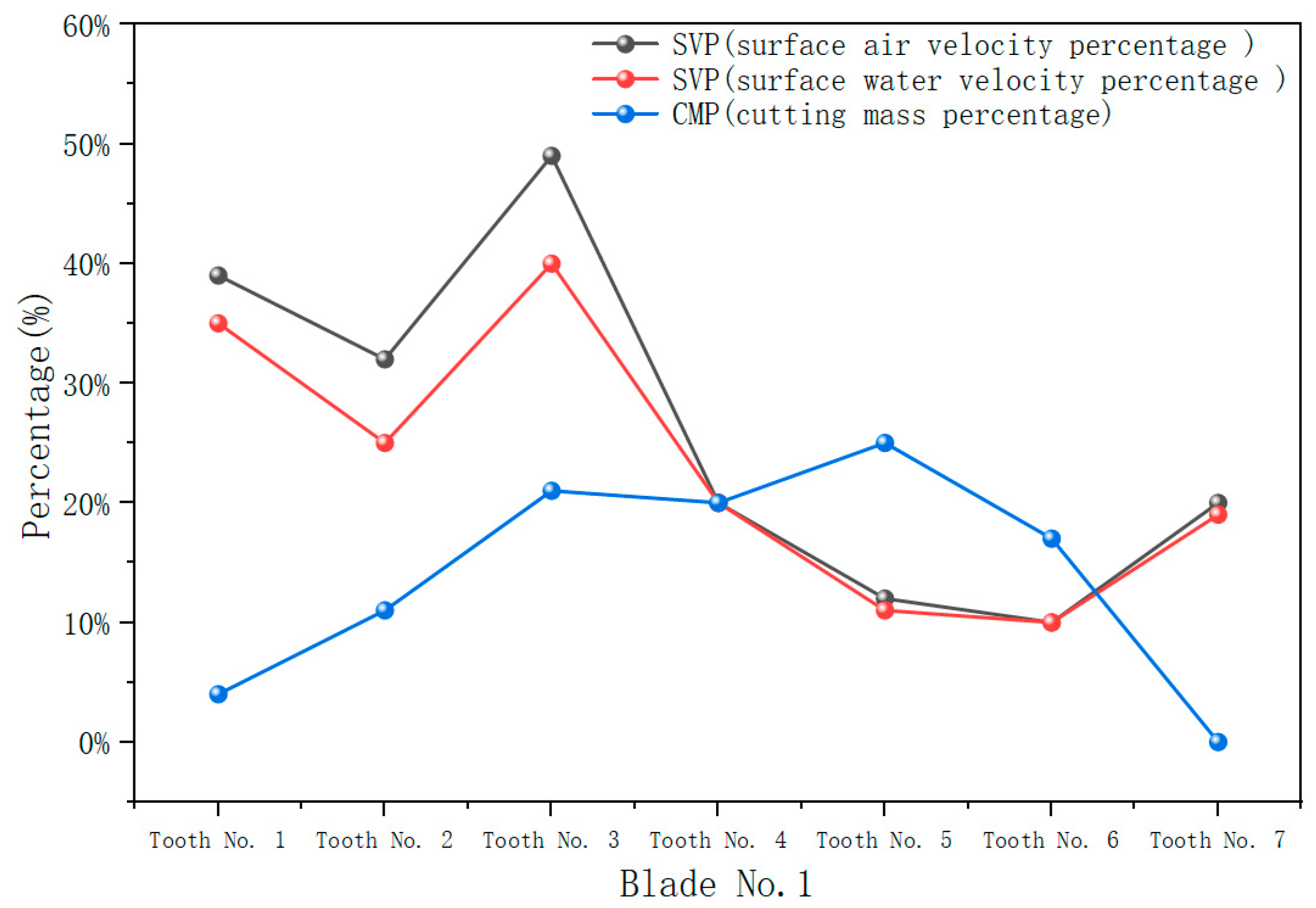
  • The distribution trends of the two broken lines should be basically the same.
  • Generally speaking, on the premise that tooth surface erosion does not occur, cutting teeth with a large cuttings mass flow rate requires a relatively high surface flow velocity to clean and cool the cutting teeth thoroughly. The surface velocity percentage of the main cutting teeth should be higher, while that of the inner bevel teeth with lower cuttings mass flow rate should be lower.
If these conditions are not met, it indicates that the hydraulic structure of the drill bit requires further optimization and improvement to maximize the hydraulic energy of the PDC drill bit.

2.3.2. Flow Channel Cutting Matching Evaluation Method

An excellent hydraulic structure design for a drill bit must comprehensively evaluate the drilling fluid’s effectiveness in cleaning and cooling the cutting teeth. Additionally, it should ensure that the cuttings removed from the cutting teeth’s surface are promptly and efficiently transported out of the well bottom through their respective flow channels. During the drilling process, cuttings move with the flow of the drilling fluid. If the hydraulic structure is not designed properly, a fluid vortex may form at the bottom of the well, causing the cuttings to remain at the bottom and fail to be discharged from the bottom in time. In addition, some cuttings may not be discharged from their corresponding flow channels and be transported to other channels and eventually discharged from the bottom of the well through other flow channels. This phenomenon is called cuttings cross-flow. Cuttings cross-flow increases the residence time and movement path of the cuttings at the bottom of the well, thereby raising the risk of bit-balling and potentially exacerbating the erosion of the drill bit and cutting teeth [20]. Therefore, in the hydraulic structure design of PDC drill bits, efforts should be made to minimize or eliminate cuttings cross-flow between flow channels. Ideally, cuttings should be quickly transported out of the wellbore by the drilling fluid without any occurrence of vortices or cuttings cross-flow, achieving the shortest transportation path to the annulus. This results in the optimal hydraulic energy distribution and cuttings removal capability at the bottom of the well. Existing literature typically uses a bottom-hole flow velocity vector cloud diagram and a streamline diagram for qualitative assessments of vortices and cuttings cross-flow. However, there is a lack of objective quantitative analysis regarding the hydraulic energy distribution in the flow channels and the extent of cuttings cross-flow. Reasonable distribution of hydraulic energy aims to allocate fluid flow appropriately based on the amount of cuttings on each blade, ensuring the effective cleaning and cooling of each blade. Therefore, we propose a new quantitative evaluation method, the flow channel cutting matching evaluation method. This method uses the flow channel cuttings matching value ( M i ) to quantitatively analyze and judge the discharge of cuttings from each flow channel. The calculation equation is:
M i = B i C i
where i ranges from 1 to n , and n is the actual number of flow channels;
  • B i is the ratio of the cuttings mass flow rate discharged by the i -th flow channel to the total cuttings discharged from all flow channels;
  • C i is the ratio of the cuttings mass flow rate generated by the i -th blade to the total cuttings generated by all blades.
  • If M i = 1, it signifies an ideal state where the amount of discharged cuttings matches precisely with the amount of generated cuttings, indicating a reasonable distribution of hydraulic energy. When the value of M i is closer to 1, it means that the cross-flow phenomenon of rock cuttings is less severe, the travelling distance of rock cuttings is shorter, and the possibility of accumulation is smaller, thus reducing the risk of balling in the drill bit.
  • If M i ≠ 1, it indicates that the hydraulic energy distribution is unreasonable, resulting in more or less cuttings discharged from some flow channels than the initial cuttings generated on the corresponding blade. This indicates that a certain extent of cuttings cross-flow phenomenon has occurred between the flow channels, and some cuttings have been moved to other flow channels by drilling fluid, which increases the movement time and movement path of cuttings at the bottom of the well, making it impossible for cuttings to be discharged from the bottom of the well in time. Therefore, when designing the hydraulic structure of the PDC drill bit, the cross-flow of cuttings between the flow channels should be minimized or avoided, and the hydraulic structure of the drill bit should be optimized by properly adjusting the position of the nozzle or the injection angle.

2.3.3. Drill Bit Body Erosion Evaluation Method

The drilling fluid must ensure effective cleaning and cooling of the drill bit while preventing erosion from excessive hydraulic energy [30,31]. As the cutting teeth continue to cut, the high-speed drilling fluid jet exits the nozzle, carrying cuttings particles of various sizes to the bottom of the well. The uneven impact pressure of the jet causes the cuttings at the bottom of the well to rebound, forming a complex multiphase flow mixture of drilling fluid and cuttings particles, which act as abrasives [32,33]. As the drilling fluid circulates, the cuttings continuously collide with the drill bit’s body, potentially causing erosion. We use numerical simulation to qualitatively analyze the erosion of the PDC bit’s body and cutting teeth from cuttings. According to the Finnie erosion model, the PDC drill bit surface’s erosion rate is the sum of all particles’ erosion rates, indicating the mass of material eroded per square meter per unit of time.
For transient flow field analysis, erosion on the PDC bit surface changes over time. Simply using the surface erosion rate to express erosion is not accurate enough. Instead, we use the accumulated erosion rate over time to represent the erosion of the PDC drill bit. This metric indicates the mass of material eroded per square meter during the total simulation time. The total erosion rate cloud chart of the bit surface can be obtained through numerical simulation calculations in CFD post-processing. This chart is used to assess the extent of the erosion of the drill bit. If erosion occurs, the hydraulic structure must be adjusted to avoid or reduce erosion, especially on the cutting tooth and blade end surfaces.

3. Results

3.1. Bottom-Hole Flow Velocity

After post-processing the numerical simulation results, Figure 4 presents the bottom-hole flow velocity contour in air and water media. The figure indicates that the bottom-hole flow velocity peaks around the central nozzle and gradually decreases outward, highlighting the central nozzle’s crucial role in influencing flow dynamics. Although the flow velocity distributions in air and water media are similar, the flow velocity in air is slightly higher than in water. This difference suggests that the properties of the medium significantly impact the overall flow velocity distribution, which will be further analyzed in the Section 4.

3.2. Cutting Tooth Ceaning and Cooling Efficiency Results

After completing the numerical simulation, CFD post-processing software is used to obtain the average air velocity and water velocity at the nozzle outlets corresponding to each blade, as well as the average air velocity and water velocity on the surface of each cutting tooth. These values are then substituted into Equation (15) to calculate the SVP values for each blade. Subsequently, Equation (16) is used to calculate the percentage of the cuttings mass flow rate for each cutting tooth relative to the total cuttings mass flow rate of the corresponding blade, referred to as CMP. Finally, a line chart is plotted to visualize the results, as shown in Figure 5, Figure 6, Figure 7, Figure 8, Figure 9 and Figure 10.
Figure 5 shows that the surface velocity percentage in the air medium is generally higher than in the water medium, with both having similar directional distributions. However, the trend distribution of the surface velocity and cutting mass percentage for each cutting tooth varies significantly. Specifically, the main cutting teeth (teeth No. 4, No. 5, and No. 6) with higher cuttings mass flow rate have lower tooth surface flow velocity, indicating insufficient hydraulic energy. This inadequacy can affect the cleaning and cooling of the main cutting teeth, leading to cuttings accumulation. Cuttings cannot be cleaned in time and accumulate on the drill bit surface and around the cutting teeth, leading to bit-balling, which increases friction and resistance. Insufficient cooling causes the drill bit to overheat, leading to thermal fatigue and material wear, significantly impacting drilling efficiency. Conversely, Teeth No. 1, No. 2, and No. 7, with lower cuttings mass flow rates, have higher tooth surface flow velocity, indicating excessive hydraulic energy wastage. However, these teeth have good cleaning and cooling effects and may suffer erosion damage.
Figure 6 shows that the surface velocity percentage in the air medium is generally higher than that in the water medium, and the directional distribution of the two is similar. The distribution trend of surface velocity and cutting mass percentage among the cutting teeth on the No. 2 secondary blade is generally similar. Specifically, teeth No. 1 and No. 2, with higher cutting mass flow rates, exhibit higher surface flow velocities, whereas teeth No. 3 and No. 4, with lesser cutting mass flow rates, show relatively lower velocities. This suggests that the overall cleaning and cooling effectiveness of the No. 2 secondary blade is satisfactory. However, the higher overall flow velocity poses a potential risk of erosion damage. Therefore, integrating the erosion simulation results of the drill bit is necessary to comprehensively analyze the reasonableness of the hydraulic structure of this blade.
Figure 7 reveals that the No. 3 main blade exhibits the same phenomenon as the No. 1 main blade, with significant differences in the trend distribution of the SVP and CMP among the cutting teeth. Specifically, teeth No. 4 and No. 5, which have the highest cuttings mass flow rates, exhibit the lowest surface flow velocities, whereas teeth No. 1, No. 6, and No. 7, with lower cuttings mass flow rates, show higher surface flow velocities. This indicates that the hydraulic energy distribution for this blade is unbalanced. Inadequate cleaning and cooling of teeth No. 4 and No. 5 can lead to bit-balling and thermal wear damage to the cutting teeth. Conversely, excessive hydraulic energy on teeth No. 1, No. 6, and No. 7, while ensuring good cleaning and cooling, may cause erosion damage.
Figure 8 shows that the value of SVP under the air medium is generally higher than that under the water medium, and the distribution of the two is the same. In the No. 4 secondary blade, the overall surface flow velocity of the cutting teeth is relatively high. However, there are noticeable differences in the trend distribution between the SVP and the CMP. The surface flow velocity of tooth No. 2, which has the highest cuttings mass flow rates, is relatively low, potentially impacting its cleaning and cooling efficiency. Conversely, the surface flow velocity for teeth No. 4 and No. 5, which have lower cuttings mass flow rates, is relatively high, resulting in a waste of hydraulic energy. The jet angle and nozzle installation position can be adjusted accordingly to optimize the hydraulic structure and achieve a reasonable distribution of hydraulic energy.
Figure 9 shows that the hydraulic structural design of the No. 5 main blade exhibits issues similar to those of the No. 1 and No. 3 main blades. There is a significant discrepancy between the distribution trends of the SVP and the CMP for each cutting tooth. Notably, the teeth with the highest cuttings mass flow rates, teeth No. 4 and No. 5, have the lowest surface flow velocities, which could adversely affect the cleaning and cooling effectiveness of the drilling fluid on these teeth, leading to potential issues such as bit-balling and thermal wear. In severe cases, this could result in tooth breakage, significantly impacting drilling efficiency and increasing costs. Additionally, the No. 3 cutting tooth has the highest surface flow velocity, which may cause erosion damage. This requires analysis in conjunction with the erosion simulation results of the drill bit to make more reasonable adjustments to the hydraulic structure around this blade.
Figure 10 shows the overall surface flow velocity of the No. 6 blade is relatively high and shows an increasing trend, but it does not match the distribution of the line graph of the CMP of each cutting tooth. Specifically, tooth No. 2 has the highest cuttings mass flow rates and has a relatively low surface flow velocity. In contrast, teeth No. 4 and No. 5, which have lower cuttings mass flow rates, exhibit the highest surface flow velocities. This discrepancy leads to a waste of hydraulic energy. Although the surface flow velocity of tooth No. 2 remains high and should ensure adequate cleaning and cooling of the tooth surface, the evaluation principle of matching high cuttings mass flow rates with high flow velocities and low cuttings mass flow rates with low flow velocities suggests that adjustments to the nozzle spray angle and other structural parameters are necessary. Ensuring optimal and scientific hydraulic energy distribution will improve drilling efficiency and reduce drilling costs.

3.3. Matching Results of Flow Channel Cutting Removal Volume

Combining the rock-breaking simulation and numerical simulation results, we measured the mass flow rates of rock cuttings generated by each blade and the mass flow rates of rock cuttings discharged from each flow channel. We substituted the above values into Equation (17) for calculation to obtain the value of M i for each flow channel, and the analyses results shown in Figure 11 were obtained after integrating the data.
Figure 11 illustrates significant differences in the cuttings discharge matching across various channels. The matching values for cuttings discharged from channels No. 1 and No. 2 are close to 1, suggesting that these channels discharge cuttings in alignment with those generated by the blades. The cuttings discharge matching values for channels No. 3 and No. 5 are significantly higher than 1, approximately 1.2, indicating that the cuttings mass flow rates discharged from these two channels are notably higher than the mass flow rate of cuttings generated by the blades. In contrast, channels No. 4 and No. 6 exhibit matching values below 1, approximately 0.8, indicating a discharge of cuttings from channels lower than those generated by the blades. According to the evaluation method in Section 2.3.2, the increased cuttings mass flow rates discharge from channels No. 3 and No. 5 and decreased discharge from channels No. 4 and No. 6 indicate significant cross-flow of cuttings among these channels. This discrepancy between discharged and generated cuttings suggests an improper distribution of hydraulic energy. This cross-flow phenomenon may increase the movement distance of cuttings, leading to accumulation and erosion of the drill bit body, thereby impacting drilling efficiency and the bit’s lifespan.

3.4. Blade Surface Erosion Results

Figure 12, Figure 13, Figure 14, Figure 15, Figure 16 and Figure 17 show the erosion of each blade in the gas-liquid-solid flow field.
Figure 12, Figure 13, Figure 14, Figure 15, Figure 16 and Figure 17 illustrate the varying extent of erosion observed on the surface of the PDC drill bit. The key findings are as follows:
  • Severe Erosion: The most severe erosion was observed on the No. 3 tooth of the No. 2 secondary blade, which exhibited the highest total erosion rate among all the cutting teeth. It may cause erosion damage to the cutting tooth surface and cutting tooth base in this area. Once an erosion pit is formed, the fluid will undergo a more violent vortex phenomenon, aggravating the erosion of the tooth surface and tooth base, which may eventually lead to tooth loss or tooth breakage.
  • Moderate Erosion: The cutting teeth’ surface at each blade’s crown has also been eroded, which may affect the rock-breaking efficiency of PDC cutting teeth. Moderate erosion was seen on the No. 3 and No. 4 teeth of the No. 5 main blade, the No. 3 tooth of the No. 1 blade, the No. 3 tooth of the No. 3 blade, the No. 3 tooth of the No. 4 blade, and the No. 3 tooth of the No. 6 blade.
  • Erosion Distribution: The erosion patterns suggest that certain cutting teeth are more susceptible to erosion. The distribution of erosion suggests a strong correlation with the flow dynamics and the placement of nozzles on the drill bit. High-velocity jets impacting specific cutting teeth likely contribute to the observed erosion patterns. The data highlights the need for optimized nozzle placement and angle and protective measures for more vulnerable teeth to enhance the durability of the PDC drill bit.

4. Discussion

The numerical simulation technology established in this study effectively simulates the bottom-hole flow field characteristics of the PDC drill bit in foam drilling. It comprehensively evaluates its hydraulic structure using both quantitative and qualitative methods. The simulation of a specific six-blade PDC drill bit, as shown in Figure 4, reveals a generally high bottom-hole flow velocity without any significant low-speed areas, facilitating the rapid migration of bottom-hole cuttings, resulting in an effective cutting removal process. The peak flow rate appears around the central nozzle area and gradually weakens outward because the drilling fluid is injected into the bottom of the well at high speed through the nozzle. The migration of cuttings and the cooling of the drill bit body mainly rely on the jet’s impact on the bottom of the well. The jet’s rock-carrying ability can be roughly assessed by analyzing the bottom-hole flow velocity contour. Our result is consistent with the findings of Yang Yingxin [34], who concluded that the bottom-hole flow velocity distribution gradually weakens from the center to the periphery. The bottom-hole cutting removal effect can be preliminarily judged by analyzing the bottom-hole flow velocity contour, which indirectly confirms the reliability of the gas-liquid-solid three-phase flow numerical simulation established in this study.
Furthermore, the slightly higher flow rate in the air medium compared to the water medium can be attributed to the lower density and viscosity of air. Air, being less dense, experiences less resistance under similar conditions, leading to a higher flow rate. Additionally, the lower viscosity of air reduces friction between air molecules during flow, further contributing to the higher flow rate. Hence, the air medium typically exhibits a higher flow rate at the same flow rate than the water medium. This observation is consistent with the study by Shen Yan [35], which noted that low-density mediums help improve flow rates and cuttings removal efficiency. These characteristics explain why foam drilling fluid, rather than water-based drilling fluid, is often used in high-temperature geothermal wells. Foam drilling fluid has lower density and viscosity compared to water-based fluids and does not easily undergo phase changes or degradation in high-temperature environments, maintaining its good fluidity and cooling performance. Moreover, the density of foam drilling fluid can be adjusted by varying gas–liquid ratios to suit different bottom-hole pressures and drilling requirements. Therefore, using foam drilling fluid in high-temperature geothermal wells can better address challenges in such environments, improving drilling efficiency and success rates.
Based on the principle that cutting teeth with high cutting mass flow rates should have a high flow velocities distribution, we establish a quantitative evaluation method for assessing the cleaning and cooling effects of cutting teeth. This method can intuitively and effectively identify problems with specific blades. As shown in Figure 5, Figure 6, Figure 7, Figure 8, Figure 9 and Figure 10, the evaluation indicators described in Section 2.3.1 reveal that each blade exhibits varying extents of unreasonable hydraulic energy distribution. Notably, the main blades No. 1, 3, and 5, responsible for the primary rock-breaking work, exhibit the most obvious problems. The surface flow velocity of the main cutting teeth on these three blades is notably low, potentially impacting their cleaning and cooling efficiency and delaying the timely removal of cuttings. Inadequate cleaning can lead to bit-balling formation on the drill bit, increasing friction and resistance. This situation seriously affects drilling efficiency, potentially causing thermal fatigue, material wear, and even overheating of the drill bit. Some peripheral and inner bevel teeth with low cutting capacity have relatively high surface flow velocities. However, high flow velocity also increases the risk of erosion damage. Therefore, the hydraulic structure should be comprehensively adjusted based on the erosion patterns on the blade surface to balance drilling efficiency and bit protection. Compared to the results of other researchers [28,29], whose studies did not consider the impact of rock cuttings and relied solely on qualitative analysis of cutting teeth cleaning and cooling effects based on the surface flow velocity contour of the drill bit, their results are not comprehensive and may lead to misjudgments in hydraulic structure analysis. In this paper, we use the SVP and CMP indicators to evaluate the cleaning and cooling effects, which allows for a more intuitive assessment of the cutting teeth’s cleaning and cooling performance.
The cross-flow of cuttings is another significant discovery. Figure 11 shows distinct differences in matching discharged cuttings from various flow channels. The matching values of discharged cuttings from flow channels No. 3 and 5 are significantly higher than 1, while those from flow channels No. 4 and 6 are below 1, which indicates that the drilling fluid transported some cuttings in flow channels No. 4 and 6 to flow channels No. 3 and 5 and eventually discharged from the flow field, resulting in the cross-flow phenomenon of cuttings. This cross-flow phenomenon increases the movement time and path of cuttings at the bottom of the well, preventing their timely discharge, which increases the likelihood of bit-balling formation and may exacerbate the erosion of the drill bit body and cutting teeth. To address this issue, adjusting the nozzle’s position, size, and diameter and improving the flow channel design should be considered, which will ensure that the discharge of cuttings in each flow channel matches the generated cuttings, optimizing hydraulic energy distribution, enhancing drilling efficiency, and extending the drill bit’s service life. Compared to other studies [28,29,34], which only infer the occurrence of cuttings flow through the drill bit surface flow velocity vector cloud diagram or streamline diagram, our research provides a more detailed assessment of the extent and specific distribution of cuttings flow. Our research results offer an intuitive understanding of the cuttings removal situation in each flow channel through data analysis.
In addition, the 6-blade PDC drill bit experienced significant erosion damage, with the highest total erosion rate observed on tooth No. 3 of blade No. 2. Moderate erosion damage was also noted on tooth No. 3 of blade No. 1, tooth No. 3 of blade No. 3, tooth No. 3 of blade No. 4, teeth No. 3 and No. 4 of the main blade No. 5, and tooth No. 3 of blade No. 6. The erosion on the cutting teeth surface is likely caused by excessive hydraulic energy and uneven jet impact pressure. The reverse flow generated at the bottom surface of the drill bit encounters the cutting teeth, forming a bypass flow and generating adhesion on the back of the tooth column pier. When the surface layer breaks away to form a vortex, it may erode the cutting teeth. Therefore, designing PDC drill bits requires considering the differences in working conditions at various locations. Measures can be taken to enhance the wear and erosion resistance of the drill bit. For example, adjusting a cutting tooth’s material, shape, and arrangement can improve erosion resistance. Additionally, optimizing the hydraulic structure of the drill bit and adjusting the nozzle outlet angle can reduce the impact and wear on the cutter teeth. Regular inspection and maintenance of drill bits and timely replacement of damaged cutting teeth are also crucial for ensuring drilling efficiency and quality. The numerical simulation results of existing studies cannot directly obtain the distribution of drill bit erosion damage because they do not consider the influence of cuttings and can only indirectly judge it through the flow velocity contour of the drill bit surface [32]. However, this evaluation method is not accurate enough. Compared with the existing literature, our results can directly grasp the erosion damage of drill bits.
The numerical simulation technique employed in this study successfully simulated the bottom-hole flow field characteristics of the PDC drill bit in foam drilling. However, when using CFD post-processing simulation software, numerical simulation results were influenced by several factors that require careful consideration. Firstly, numerical simulations assume ideal fluid behavior and idealized conditions on the drill bit surface, which may deviate under certain practical operating conditions. Particularly in extreme conditions, such as high pressure and high temperature, fluid behavior can vary, and numerical simulations often struggle to capture these nonlinear effects fully. Secondly, model selection, numerical methods, and boundary condition settings significantly impact results and should be chosen cautiously to enhance result credibility. Finally, sources of error in numerical simulations include numerical perturbations, mesh quality, and numerical dissipation, which, despite optimization efforts, remain inherent and unavoidable.
Here, we focus on discussing the impact of the turbulence models chosen for this study on the numerical simulation results. In this study, we selected the standard k-ε model and the wall function model for turbulence simulation based on several important factors. The k-ε model suits most engineering flow problems, particularly high Reynolds number flows. Relevant research has shown that the k-ε model performs well in simulating the single-phase, rotational, and multiphase flow fields of PDC drill bits [23,28,29,34], providing a theoretical basis for our choice of this model. Additionally, compared to other models, the k-ε model offers lower computational costs and higher efficiency. When choosing the wall function model as a complementary model, we considered its advantages in handling turbulence near the wall. The wall function model is a semi-empirical approach that simplifies computational complexity and provides adequate precision for large-scale computations. This model connects the near-wall flow characteristics with the turbulence characteristics of the mainstream region, reducing computational effort while maintaining good stability and accuracy for high Reynolds number flows.
Based on theoretical analysis of the bottom-hole flow field and existing research conditions, we chose to use a combination of the k-ε model and the wall function model. This combination can effectively simulate the basic characteristics of the downhole flow field to a certain extent. However, due to the assumptions and simplifications inherent in these models, there are still certain limitations. The k-ε model has limitations in accurately simulating turbulence in the near-wall region. Since this model relies on wall functions to estimate turbulence characteristics near the wall, it may produce inaccurate results in complex wall geometries and extreme boundary conditions. Specifically, in cases of flow transition or very thin turbulence layers, the k-ε model may fail to capture subtle flow variations, thus affecting the precise description of boundary layer characteristics. The performance of the k-ε model under low Reynolds number conditions is not as effective as that of the k-ω model. In low Reynolds number flows, the k-ε model may not accurately predict turbulence intensity and turbulence structure, leading to deviations in simulation results. This limitation arises because the k-ε model’s flow structure becomes unstable under low Reynolds number conditions, potentially resulting in inaccurate turbulence predictions. The k-ω model has distinct advantages in handling near-wall regions, and low Reynolds number flows, particularly for complex boundary layer problems and flow transition phenomena. However, the k-ω model typically requires more computational resources and considerable computational effort. To further validate the accuracy of these models and comprehensively evaluate the performance of different turbulence models, we plan to explore the use of the k-ω model in future research and conduct a detailed comparative analysis.

5. Conclusions

The numerical simulation technology and evaluation method established in this study effectively simulated the bottom-hole flow field characteristics of the PDC drill bit in foam drilling, and evaluated its hydraulic structure through a combination of quantitative and qualitative methods. Numerical simulation of a six-blade PDC drill bit revealed that some cutting teeth have poor cleaning and cooling effects. Additionally, some cutting teeth experience erosion damage, and there was a cross-flow of cuttings in the flow channel. To address these issues, optimizing the nozzle injection angle and flow channel design is necessary to enhance hydraulic energy distribution, improve drilling efficiency, and extending the drill bit’s service life. We hypothesize that the numerical simulation of gas-liquid-solid three-phase flow more accurately reflects the hydraulic structural performance of PDC drill bits in foam drilling, and the quantitative evaluation method offers a more objective basis for design optimization. The research results validate this hypothesis, demonstrating the advantages of the established three-phase flow numerical simulation technology and evaluation method regarding simulation accuracy and systematicness and for providing more scientific and precise guidance for PDC drill bit design.

6. Future Work Recommendations

The research discussed in this article still has some limitations. Future studies could include experimental verification to validate the optimal design plan and further confirm the accuracy of the numerical calculation model for gas-liquid-solid three-phase flow. Additionally, exploring more factors related to working conditions, such as different formation types, well depths, and the properties of foam drilling fluids, could provide valuable insights for designing PDC bits for diverse working environments.
Furthermore, conducting a thorough investigation into the impact of cuttings on the bottom-hole flow field could be beneficial, as it could involve examining factors like the size, density, and shape of cuttings and the interaction mechanism between cuttings and drilling fluid. Improving the evaluation method for the hydraulic structure design of PDC bits is also essential; this could include enhancing the current method that combines qualitative and quantitative approaches to establish a more scientific and objective evaluation system, providing more accurate guidance for designing and enhancing PDC bits.
Moreover, due to the complexity of simulating the three-phase flow field in this study, certain limitations exist in the choice of models and boundary condition settings to ensure convergence. We assumed the bottom-hole flow field to be fully turbulent, which may not fully align with actual drilling conditions and requires further investigation into the precise state of the bottom-hole flow field. In the next phase of work, the k-ω model could be introduced, and a comprehensive comparative analysis between the k-ε model and the k-ω model should be conducted to evaluate their relative performance and determine the most suitable model for different applications.

Author Contributions

L.W.: conceptualization, methodology, validation, writing—original draft, writing—review and editing, conceptualization; J.H.: funding acquisition, supervision, writing—review and editing. All authors have read and agreed to the published version of the manuscript.

Funding

This study was published through a grant provided by Mapúa University.

Data Availability Statement

The original contributions presented in the study are included in the article, further inquiries can be directed to the corresponding author.

Conflicts of Interest

The authors declare no conflicts of interest.

References

  1. Hirasaki, G.J.; Lawson, J.B. Mechanisms of Foam Flow in Porous Media: Apparent Viscosity in Smooth Capillaries. Soc. Pet. Eng. J. 1985, 25, 176–190. [Google Scholar] [CrossRef]
  2. Nguyen, Q.P.; Currie, P.K.; Zitha, P.L.J. Motion of Foam Films in Diverging–Converging Channels. J. Colloid Interface Sci. 2004, 271, 473–484. [Google Scholar] [CrossRef] [PubMed]
  3. Wendorff, C.L.; Ainley, B.R. Massive Hydraulic Fracturing of High-Temperature Wells with Stable Frac Foams. In Proceedings of the SPE Annual Technical Conference and Exhibition, San Antonio, TX, USA, 4–7 October 1981. [Google Scholar]
  4. Li, Q.; Zhang, K.; Zhou, Q.; Ling, X.; Liu, B.; Wang, Y. Analysis of the Influence of Cutting Depth on the Ultra-High-Speed Rock Breaking Mechanism of PDC Cutters. Pet. Mach. 2022, 50, 1–8. [Google Scholar]
  5. Wang, J.; Zou, D.; Yang, G.; He, R.; Chen, X. Interaction Model between PDC Cutting Teeth and Rocks. J. China Univ. Pet. (Ed. Nat. Sci.) 2014, 38, 104–109. [Google Scholar]
  6. Xu, A. Analysis of the Rock-Breaking Load Law of PDC Drill Bit Cutting Teeth. Explor. Eng. (Rock Soil Drill. Eng.) 2006, 7, 59–61. [Google Scholar]
  7. Luo, W. Analysis of Cuttings from PDC Drill Bits at Different Wear Stages under Different Drilling Parameters. China New Technol. New Prod. 2010, 13, 126. [Google Scholar]
  8. Huang, Z.; Shan, D.; Li, Q.; Tan, J.; Yang, M.; Liu, S. Numerical Simulation Study on Bottom Hole Flow Field of Down-the-Hole Drill Bit. Pet. Mach. 2006, 8, 11–18. [Google Scholar]
  9. Wells, M.; Marvel, T.; Beuershausen, C. Bit Balling Mitigation in PDC Bit Design. In Proceedings of the IADC/SPE Asia Pacific Drilling Technology Conference and Exhibition, Jakarta, Indonesia, 25–27 August 2008. [Google Scholar]
  10. Moslemi, A.A.; Rahmani, R.; Graham, R.; Ivie, B. Hydraulic Design of Shale DrillBit Using an Integrated Numerical and Experimental Approach. In Proceedings of the SPE/IADC Drilling Conference and Exhibition, London, UK, 17–19 March 2015. [Google Scholar]
  11. Gerbaud, L.; Menand, S.; Sellami, H. PDC Bits: All Comes from the Cutter/Rock Interaction. In Proceedings of the IADC/SPE Drilling Conference, Miami, FL, USA, 21–23 February 2006. [Google Scholar]
  12. Rahmani, R.; Smith, J.R.; Taleghani, A.D. Analytical Modeling of PDC Single Cutter-Rock Interaction Under Confining Pressure. In Proceedings of the 46th U.S. Rock Mechanics/Geomechanics Symposium, Chicago, IL, USA, 24–27 June 2012. [Google Scholar]
  13. Jiang, X.; Duan, L.; Liu, Z. Experimental Study on Erosion Wear of Mud on WC-Based Matrix Material of Drill Bit. Coal Geol. Explor. 2007, 4, 77–80. [Google Scholar]
  14. Xing, X.; Xu, Y.; Yang, Y.; Wang, G. Study on Erosion Characteristics of Particle Impact Drilling Bit Internal Flow Channel. Pet. Mach. 2015, 43, 39–43. [Google Scholar]
  15. Zhao, J.; Zhang, G.; Xu, Y.; Wang, R.; Zhou, W.; Yang, D. Experimental and Theoretical Evaluation of Solid Particle Erosion in an Internal Flow Passage within a Drilling Bit. J. Pet. Sci. Eng. 2018, 160, 582–596. [Google Scholar] [CrossRef]
  16. Zhao, J.; Zhang, G.; Xu, Y.; Wang, R.; Zhou, W.; Han, L. Wear of WC-Based Matrix Material of Drill Bit Internal Flow Channel under Solid-Liquid Two-Phase Flow Particle Erosion. J. Cent. South Univ. (Nat. Sci. Ed.) 2018, 49, 1228–1236. [Google Scholar]
  17. Wang, Y.; Zhang, S.; Wang, W.; Lv, L. Numerical Simulation and Simulation of PDC Drill Bit under Rotating Flow Field. Yunnan Chem. Ind. 2019, 46, 174–175. [Google Scholar]
  18. Wu, Z.; Wang, Y.; Pan, Y.; Wang, W.; Lv, L. Comparative Study on Numerical Simulation of Rotating Flow Field and Non-Rotating Flow Field of PDC Drill Bit. Oilfield Mach. 2020, 49, 10–15. [Google Scholar]
  19. Guo, B.; Miska, S.; Hareland, G. A Simple Approach to Determination of Bottom Hole Pressure in Directional Foam Drilling. ASME Drill. Technol. Symp. 2005, 65, 329–338. [Google Scholar]
  20. Zhai, Y.; Wang, Z.; Zhang, T. Experimental study on the annular cuttings migration rules in the horizontal section of aerated underbalanced drilling. Sci. Technol. Technol. Eng. 2016, 25, 8–11. [Google Scholar]
  21. Ming, Y.; Lan, Q.; Li, H.; Liu, Z.; Bu, F. Research and field testing of high temperature resistant foam drilling fluid in deep wells. Pet. Drill. Tech. 2018, 46, 47–53. [Google Scholar]
  22. Guo, L. Two-Phase and Multiphase Flow Dynamics; Xi’an Jiaotong University Press: Xi’an, China, 2002; pp. 23–26. [Google Scholar]
  23. Li, J.; Bian, C.; Liu, Z.; Hou, H. Study on Flow Field Characteristics of Rotary Cutting PDC Bit Based on DPM Model. Pet. Mach. 2021, 49, 24–32. [Google Scholar]
  24. Pu, G. ANSYS Workbench Basic Tutorials and Detailed Examples, 2nd ed.; China Water Conservancy and Hydropower Press: Shanghai, China, 2013; pp. 48–56. [Google Scholar]
  25. Burns, A.D.; Frank, T.; Hamill, I.; Shi, J.M. The favre averaged drag model for turbulent dispersion in Eulerian multi-phase flows. J. Fluid Mech. 2004, 392, 67–93. [Google Scholar]
  26. Wang, F. Principles and Applications of CFD Software for Computational Fluid Dynamics Analysis; Tsinghua University Press: Beijing, China, 2004; pp. 5–8. [Google Scholar]
  27. Kalitzin, G.; Medic, G.; Iaccarino, G.; Durbin, P. Near-wall behavior of RANS turbulence models and implications for wall functions. J. Comput. Phys. 2005, 204, 265–291. [Google Scholar] [CrossRef]
  28. Li, W.; Yang, H.; Liu, S. Simulation Study on Flow Field Characteristics of PDC Bit Rotating Nozzle. Oilfield Mach. 2023, 52, 26–32. [Google Scholar]
  29. Chen, Z.; Wang, M.; Li, X.; Shi, H.; Fan, Y.; He, W. Numerical simulation research and field test of bottom hole flow field of PDC drill bit. Drill. Prod. Technol. 2023, 46, 85–93. [Google Scholar]
  30. Bitter, J.G. A Study of Erosion Phenomena Part I. Wear 1963, 6, 5–21. [Google Scholar] [CrossRef]
  31. Bitter, J.G. A Study of Erosion Phenomena Part II. Wear 1963, 6, 169–190. [Google Scholar] [CrossRef]
  32. Liu, X. Numerical Simulation of Erosion Wear in Spiral Axial Flow Mixed Transportation Pump Inlet Pipeline; China University of Petroleum (Beijing): Beijing, China, 2018. [Google Scholar]
  33. Tilly, G. A Two-Stage Mechanism of Ductile Erosion. Wear 1973, 23, 87–96. [Google Scholar] [CrossRef]
  34. Yang, Y.; Qin, C.; Kuang, Y. Numerical Simulation and Comparison of Static and Rotating Flow Fields of PDC Drill Bits. Drill. Prod. Technol. 2015, 38, 82–85. [Google Scholar]
  35. Shen, Y.; Liu, J.; Cheng, X. Application of Foam Drilling Technology in Kenya OW904 Ultra-High-Temperature Geothermal Well. J. Chongqing Univ. Sci. Technol. (Nat. Sci. Ed.) 2009, 11, 16–32. [Google Scholar]
Figure 1. 3D model of 6-blade PDC drill bit.
Fluids 09 00211 g001
Figure 2. Schematic diagram of the model of the bottom hole flow field calculation domain: (a) is the plan view; (b) is the bottom view.
Fluids 09 00211 g002
Figure 3. Bottom-hole flow field grid.
Fluids 09 00211 g003
Figure 4. Bottom-hole flow velocity contour: (a) is the velocity of air; (b) is the velocity of water.
Fluids 09 00211 g004
Figure 5. Surface velocity distribution of blade No. 1.
Fluids 09 00211 g005
Figure 6. Surface velocity distribution of blade No. 2.
Fluids 09 00211 g006
Figure 7. Surface velocity distribution of blade No. 3.
Fluids 09 00211 g007
Figure 8. Surface velocity distribution of blade No. 4.
Fluids 09 00211 g008
Figure 9. Surface velocity distribution of blade No.5.
Fluids 09 00211 g009
Figure 10. Surface velocity distribution of blade No. 6.
Fluids 09 00211 g010
Figure 11. Matching Diagram of Flow Channel Discharge Cuttings.
Fluids 09 00211 g011
Figure 12. Total Erosion Rate of Blade No. 1.
Fluids 09 00211 g012
Figure 13. Total Erosion Rate of Blade No. 2.
Fluids 09 00211 g013
Figure 14. Total Erosion Rate of Blade No. 3.
Fluids 09 00211 g014
Figure 15. Total Erosion Rate of Blade No. 4.
Fluids 09 00211 g015
Figure 16. Total Erosion Rate of Blade No.5.
Fluids 09 00211 g016
Figure 17. Total Erosion Rate of Blade No.6.
Fluids 09 00211 g017
Table 1. Mesh-independent analysis.
Mesh SchemeMinimum Mesh Size (mm)Cutting Tooth Velocity (m/s)
Coarse Mesh314.712
Medium Mesh1.515.267
Fine Mesh115.324
Table 2. The rock-breaking simulation results of the No. 1 blade.
Cutting ParametersTooth No. 1Tooth No. 2Tooth No. 3Tooth No. 4Tooth No. 5Tooth No. 6Tooth No. 7
Cuttings Mass Flow Rate (kg/s)0.0040.0140.0250.0240.0280.0180.001
initial velocity (m/s)0.1070.350.5920.8511.0961.2491.281
direction of movement (X)0.0160.0050.038−0.169−0.609−0.882−0.902
direction of movement (Y)0.3260.3440.3650.2410.004−0.149−0.086
direction of movement (Z)−0.909−0.901−0.883−0.904−0.716−0.2870.002
Table 3. The initial cuttings mass flow rate of each blade.
Blade NumberBlade No. 1Blade No. 2Blade No. 3Blade No. 4Blade No. 5Blade No. 6
Cuttings Mass Flow Rate (kg/s)0.1140.0690.1010.0810.1080.071
Disclaimer/Publisher’s Note: The statements, opinions and data contained in all publications are solely those of the individual author(s) and contributor(s) and not of MDPI and/or the editor(s). MDPI and/or the editor(s) disclaim responsibility for any injury to people or property resulting from any ideas, methods, instructions or products referred to in the content.

