Abstract
The paper describes new combined heating capability of the IPMech RAS inductively coupled plasma facility VGU-4. A 200 W ytterbium laser was added to the facility as a source of radiative heating. The cylindrical specimen made of the Buran orbital vehicle’s heat-shielding tile material with a black low catalytic coating was exposed to subsonic pure nitrogen plasma jet and laser radiation. The specimen surface temperature reached 1325 C during combined radiative and convective heating. The maximum heat flux obtained in the combined mode for a laser incident power of 47 W and a VGU-4 HF-generator anode power of 22 kW was 32.1 W/cm. The convective heat flux from the nitrogen plasma jet at the same anode power was 12.6 W/cm. Adding a laser to an existing inductively coupled plasma facility gives the future opportunity to better simulate entry into the atmospheres of Mars, Venus, the outer planets and their moons.
1. Introduction
Arc-jet plasma torches and inductively coupled plasma (ICP) facilities (plasmatrons) are widely used in experiments on modeling thermochemical interaction of dissociated flow with material surface in Russia (TsNIIMash [1], TsAGI [2], IPMech RAS [3]), the USA [4,5] and Europe [6]. The technical solutions that made it possible to design powerful high-frequency induction plasmatrons are based on the works of G.I. Babat [7] and the idea of vortex stabilization proposed by T. Reed [8]. To date, several powerful electrodeless plasmatrons have been created to study the heat transfer processes in high-enthalpy gas flows and to test thermal protection materials. In Russia, there are a 1 MW plasmatron U-13VCHP in TsNIIMash [1], a 250 kW plasmatron VAT-104 in TsAGI [2] and 1 MW and 100 kW plasmatrons VGU-3 and VGU-4 in IPMech RAS [9]. In Western Europe, there are a 1200 kW plasmatron at the von Karman Institute for Fluid Dynamics [10] and at the PWK3 facility in Germany [11]. In the USA, the University of Texas at Austin and the University of Vermont have developed small 50 kW and 30 kW inductively coupled plasma torches [12,13]. Experiments on heat exchange in jets of high-frequency induction plasmatrons have also been carried out in Japan [14] and China [15].
It is possible to distinguish a number of main scientific tasks for modern high-power electrodeless plasmatrons:
- Thermochemical resistance of materials [16,17,18,19,20];
- Catalytic properties of materials in a dissociated gas with respect to a heterogeneous recombination of atoms [21,22,23,24];
- Compliance with the laboratory tests of the thermochemical effect on the material, realized during the movement of the body at high speed in the atmosphere [25,26].
Studies of the thermochemical resistance of the materials are also carried out in arc-jet plasma torches in Russia [1], the USA [27,28], Europe [29,30,31] and China [32]; however, the contamination of the flow with electrode destruction products makes it difficult to use such facilities in problems sensitive to the chemical purity of gas (for example, for the study of heterogeneous catalysis).
Along with modeling the entry into the Earth’s atmosphere, ground tests of thermal protection systems for missions to Mars, Venus, the outer planets and their moons are also of great interest [33,34,35,36,37,38,39,40,41,42,43,44].
Arc-jet and inductively coupled plasma facilities provide convective heating of a specimen surface. The addition of a laser radiation source can expand their abilities in modeling the actual atmospheric entry conditions. In this case, it is possible to combine radiation and convective heating environments. A combined heating mode by plasma flow and laser radiation has been implemented at the Interaction Heating Facility (IHF) in the USA (Ames Research Center). As part of the Orion program, the capabilities of the IHF facility with a power of 60 MW were significantly expanded due to the use of ytterbium laser radiation sources that provided additional radiation heating of the surface of material specimens. The complex of the Laser-Enhanced Arc-jet Facility (LEAF) was created [45,46,47,48]. The LEAF facility used a 50 kW fiber-optic laser system. A water-cooled semiconductor laser was used in [49] for the combined heating of a SiC specimen surface in the arc-jet plasma wind tunnel. It should be mentioned that laser facilities that provide only radiative heating are also used for ground tests [50,51].
This work demonstrates the possibilities of new combined heating modes of the VGU-4 ICP facility at the Ishlinsky Institute for Problems in Mechanics RAS. The heat-shielding material specimen was exposed to a subsonic jet of nitrogen plasma and additionally heated by an ytterbium laser radiation.
The motivation for this study was to show that it was possible to significantly expand the operating envelope of high-power plasmatrons without a global rebuild. This is important because facilities of this type have long creation and use times and often do not meet the new challenges of the aerospace industry.
2. Materials and Methods
This study was done in subsonic pure nitrogen plasma jets of the VGU-4 HF-plasmatron with a vortex gas stabilization manufactured by the Ishlinsky Institute for Problems in Mechanics RAS. Its general parameters are specified in Table 1. A detailed description of the VGU-4 HF-plasmatron is given in [9]. The VGU-4 HF-plasmatron has a vertical orientation of its discharge channel and the plasma jet moves vertically upwards. The important feature of the VGU-4 facility is the use of a quartz discharge channel without any forced cooling [52].

Table 1.
General parameters of the VGU-4 HF-plasmatron.
A conceptual sketch of the experiment is shown in Figure 1. The test cylindrical specimen of 30 mm in diameter with a rounded face was made of the heat-shielding tile material for the Buran orbital vehicle (TZMK-10 heat insulation) with a black low catalytic coating [53,54,55,56,57,58,59,60], its main properties are presented in Table 2. The detailed specimen geometry is shown in Figure 2, its photos before exposure are shown in Figure 3.
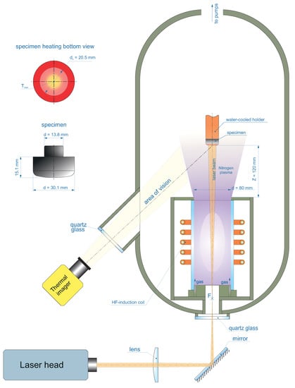
Figure 1.
Conceptual sketch of experiment.
Table 2.
Main properties of the TZMK-10 heat-shielding material with a black low catalytic coating.
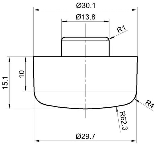
Figure 2.
TZMK-10 heat-shielding material specimen geometry.

Figure 3.
TZMK-10 heat-shielding material specimen: (a) Front view. (b) Side view.
The experiment was carried out at a constant HF-generator anode power value of 22 kW. A low anode power was chosen to prevent overheating of the specimen. The mass flow rate of nitrogen through the discharge channel was 2.4 g/s and was controlled by a Bronkhorst MV-306 flow meter. The pressure in the test chamber was 100 hPa. The distance from the outlet section of the discharge channel to the specimen was 120 mm. A Tandem VS-415U thermal imager was used to record the temperature distribution over the specimen surface: thermal images were recorded at a set value of spectral emissivity of 0.87 at a wavelength of 0.65 microns (a narrowband filter for this wavelength was used to eliminate the influence of the laser radiation) [60]. To obtain thermal images, a correction factor of 0.93 was used for the transmission of the pressure chamber quartz window. The thermal imager was calibrated according to the absolutely black-body model in the temperature range from 800 to 1500 C (for the chosen light filter).
An IPG Photonics YPLN-1-100-200-R pulsed fiber ytterbium laser with a wavelength of 1.064 microns was added to the VGU-4 ICP facility in this work to provide radiative heating. Details for the YPLN-1-100-200-R laser are presented in Table 3.
Table 3.
General parameters of the YPLN-1-100-200-R ytterbium laser.
A laser radiation source is an infrared fiber laser with a high beam directivity and emission stability. A short-wavelength infrared laser (1.064 μm) was chosen due to its high radiation absorption coefficient for a wide range of materials.
For experiments on heating materials, the operating mode with a high pulse repetition rate was chosen. At a pulse repetition rate of 1 MHz, the pulse power was just several times higher than the average power. For surface heating, a high-repetition-rate laser mode practically does not differ from a CW one.
An external optical system was designed to transport radiation from the laser head to the specimen surface along the induction plasmatron jet axis forming the irradiation spot with a known intensity distribution. The elements of the laser beam transport system are shown in Figure 1 integrated in the HF-plasmatron system. The radiation transport system included a folding mirror designed to align the axes of the laser beam and the plasma jet. The position of the mirror and its tilt angle were adjusted using micrometer screws to fine-tune the position of the irradiation spot on the specimen surface. The size of the irradiation spot was governed by the laser beam spatial characteristics and the parameters of the lens located on the axis of the radiation transport system. The specimen was placed in the divergent part of the laser beam behind the lens focus , so that the spot size depended on the ratio of the lens focal distance to the distance from the lens to the specimen along the optical axis.
In the experiments, the specimen surface irradiance distribution in the spot was close to a Gaussian distribution with a radius of 10.25 mm. The laser beam was injected into the vacuum volume of the test chamber through a transparent quartz window.
Radiation losses on the elements of the optical system due to absorption, scattering and backreflection from transparent surfaces resulted in a lower incident laser power on the specimen than the laser output power. The dependence of the incident laser power on the set output laser power was controlled by means of precalibrated laser power meter OPHIR Starlite with thermal sensor head 50(150)A-BB-26, where 26 means the receiving pad diameter in mm. The power meter head was positioned in the divergent beam so that the ratio of the radiation spot and the receiving pad diameters was the same as on the tested specimen. When calculating the specimen surface irradiation distribution, the axial irradiation value was determined from the condition that the irradiation integral over the surface should be equal to the measured incident laser power.
3. Results
The experiment was divided in two parts.
The first part (test 22-181-1) consisted of heating the specimen only with a laser beam without exposure to a plasma jet. The specimen was mounted in the facility in the same way as in a future combined heating mode (Figure 1). The specimen was heated by laser radiation in two stages. At the first stage, the incident power of the pulsed ytterbium laser was and at the second stage, the incident power was increased to 47 W. Figure 4 shows the changes in maximum temperature in the central area of the specimen surface that occurred with the increase in the laser incident power (the temperature field in the heating area at the last second of exposure is also given). The maximum surface temperature of the specimen measured by the thermal imager reached 1197 C ().
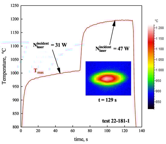
Figure 4.
Changes in maximum surface temperature in the central region of the specimen () during radiative heating by pulsed ytterbium laser, depending on the exposure parameters. Temperature field at the last second of the exposure recorded by thermal imager.
The second part of the experiment (test 22-181-2) consisted of a combined heating of the specimen with a subsonic nitrogen plasma jet generated by the VGU-4 ICP facility and laser radiation (Figure 5). The specimen was exposed to a plasma jet at a constant anode power (), and the incident power of the laser changed stepwise (from 0 to 47 W).
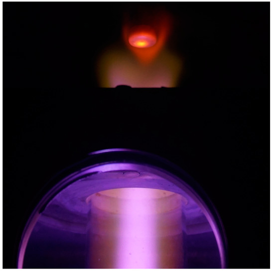
Figure 5.
Photo of specimen exposed to subsonic jet of nitrogen plasma and additionally heated by laser radiation.
Figure 6 shows the changes in the maximum temperature in the central area of the specimen surface that occurred with an increase in the laser incident power. The maximum surface temperature of the specimen measured by the thermal imager reached 1325 C (, ). The temperature in the central area of the specimen surface heated only by subsonic nitrogen plasma jet was ∼1010 C (laser off, ).
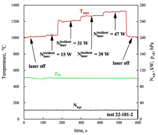
Figure 6.
Changes in maximum surface temperature in the central region of the specimen () during combined heating by pulsed ytterbium laser and subsonic nitrogen plasma jet, depending on the exposure parameters. —HF-generator anode power, —pressure in the test chamber, —laser incident power.
Thermal images of the specimen recorded for different moments of exposure are shown in Figure 7. Figure 7a shows the moment of the experiment when the surface was heated only by a subsonic nitrogen plasma jet. In Figure 7b–d, the area of the surface additionally heated by the laser beam is clearly visible.
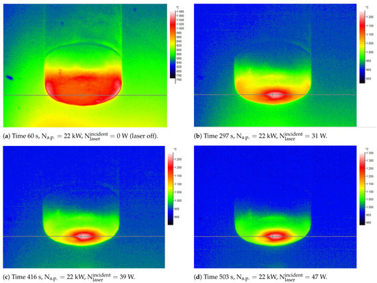
Figure 7.
Thermal images of the specimen at various stages of exposure: (a)—60 s, (b)—297 s, (c)—416 s, (d)—503 s. —HF-generator anode power, —laser incident power.
Due to the low thermal conductivity of the specimen material (the thermal conductivity of the TZMK-10 material is C) at a temperature of 800 C), the heat flux can be determined from the Stefan–Boltzmann equation excluding heat transfer through the wall:
—total emissivity, —Stefan–Boltzmann constant, T (K)—surface temperature.
The total heat fluxes in the central part of the specimen surface obtained from thermal images for various moments of the experiment are shown in Table 4. The maximum heat flux obtained in the combined heating for a laser incident power of 47 W and a VGU-4 HF-generator anode power of 22 kW was 32.1 W/cm. The convective heat flux from the nitrogen plasma jet at the same anode power was 12.6 W/cm.
Table 4.
Total heat flux.
The temperature distribution along the specimen’s diameter (indicated by horizontal lines in Figure 7) at various stages of exposure is shown in Figure 8. The x coordinate in Figure 8 is given in pixel numbers along the horizontal axis of the full frames recorded by the thermal imager from which the temperature distributions were obtained for the same y coordinate. The temperature distribution near the central region of the specimen surface under combined and laser radiative heating conditions (for laser incident powers from 31 to 47 W) was Gaussian-like. The temperature distribution near the central region of the specimen heated only by the subsonic nitrogen plasma jet was almost uniform. The low laser incident power (15 W) caused a uniform temperature increase along the specimen’s diameter.
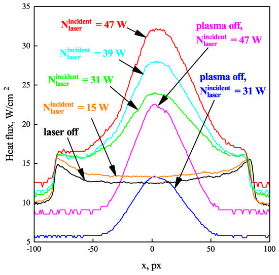
Figure 8.
Heat flux distribution along the specimen’s diameter at various stages of exposure.
4. Discussion
From the temperature graph in Figure 4, we can determine that the maximum heating rate of the specimen surface when exposed to the laser beam was 50 C/s. For a more massive and thermally conductive specimen, the heating rate under the same exposure conditions would be lower. The high heating rate is important when studying the thermal shock resistance of materials. In the considered modes, it can be flexibly controlled by changing the laser incident power.
Figure 6 clearly demonstrates the effect of the combined heating, which consisted of a stepwise increase in surface temperature as the incident laser power increases. It should be noted that after switching off the laser radiation source, the surface temperature of the specimen returned to its initial value. This fact confirmed the stability of the operation mode of the HF-plasmatron and also showed that that the emissivity of the specimen surface did not change after exposure.
As can be seen from Figure 7, the maximum heat flux during combined heating was slightly displaced relative to the geometric center of the heated surface, which can be explained by the aiming errors of the laser beam. The clear maximum in the temperature and heat flux distribution in Figure 7 and Figure 8 is due to the extremely low thermal conductivity of the specimen material. For a material with a higher thermal conductivity value (metal or carbon-based material), a more uniform distribution can be expected in the combined heating mode. For further experiments with low thermal conductivity materials, it will also be important to achieve a uniform temperature distribution, since this is critical for the studies of catalytic and radiative surface properties.
The temperatures in Figure 7 were obtained by correcting the thermal data for the spectral emissivity of the surface, which may not be known reliably for another class of material. To date, our group has not solved the technical problem of measuring temperatures above 1500 C since there are no optical pyrometry devices for high temperatures among our measuring instruments that are not affected by interference from laser radiation. In the future, it is planned to use the spectral pyrometry method [61]. The main advantage of the spectral pyrometry method is the possibility to exclude scattered laser radiation from the obtained thermal spectrum. In addition, it is not necessary to know the emissivity of the surface.
The fact that the maximum heat fluxes for the test case without exposure to laser radiation (curve “laser off” in Figure 8) were observed along the edge of the specimen can be explained by an error due to the influence of the plasma radiation reflected from the rounded edge of the specimen (the thermal imager was placed at an angle, as shown in Figure 1).
Figure 8 confirmed that the nitrogen plasma jet had no noticeable effect on the shape of the laser beam’s heat flux density distribution. This result was expected because the experiments were performed at a low pressure in the test chamber (100 hPa), and therefore at a low plasma density in the discharge region. The question of laser beam scattering with increasing pressure (up to 1 atm.) needs to be studied.
Convective heat flux to the specimen surface depends on the subsonic flow of nitrogen plasma. A deeper understanding of the investigated mode requires a numerical simulation of the subsonic jet flowing around the specimen. The Laboratory of Interaction of Plasma and Radiation with Materials of IPMech RAS developed a program package for a complete numerical simulation of a subsonic plasma flow (air, nitrogen, oxygen, carbon dioxide, argon) in the induction plasmatron [62,63]. Some modes of subsonic nitrogen plasma jets for the same discharge channel geometry were numerically simulated in [64]. For the pressure in the test chamber of the VGU-4 facility of 50 hPa and the HF-generator anode power value of kW, the enthalpy of the subsonic nitrogen plasma flow varied in the range from 26.7 to 46.4 MJ/kg. To date, preliminary calculations of the jet parameters in the outlet section of the discharge channel for the investigated combined heating mode have been performed using the above programs. For a pressure in the test chamber of 100 hPa and an HF-generator anode power value of 22 kW, the enthalpy of the subsonic nitrogen plasma flow was 20.4 MJ/kg, the velocity at the jet axis was 76 m/s and the dynamic pressure at the jet axis was 12 Pa. A more comprehensive study of plasma flow, including flow and heat exchange in the boundary layer, will be the next step of our study, as it is a separate and challenging task by itself.
5. Conclusions
The new combined heating capability of the IPMech RAS ICP facility VGU-4 was successfully demonstrated. A 200 W ytterbium laser YPLN-1-100-200-R was added to the facility as a source of radiative heating. This addition to the VGU-4 facility allows the material specimens to be simultaneously exposed to radiative and convective heating conditions and gives the future opportunity to better simulate entry into the atmospheres of Mars, Venus, the outer planets and their moons.
The VGU-4 induction plasmatron has several advantages in comparison with a similar LEAF complex created at the Ames Research Center as a result of the 60 MW arc-jet facility modernization [45]: a high chemical purity of gases and almost unlimited exposure time (up to one hour).
This work was aimed at showing the very possibility of the combined heating of the material surface by an induction plasma jet and laser radiation. The specimen made of the Buran orbital vehicle heat-shielding tile material was exposed to subsonic nitrogen plasma jet and laser radiation. The maximum heat flux obtained in the combined mode for a laser incident power of 47 W and a VGU-4 HF-generator anode power of 22 kW was 32.1 W/cm. The convective heat flux from the nitrogen plasma jet at the same anode power was 12.6 W/cm. Thus, it can be concluded that the effect of the combined radiative and convective heating was clearly demonstrated.
For the design of a spacecraft, it is necessary to know the total (convective and radiative) heating from the reentry environment, because the radiation heat transfer contributes a substantial amount of energy transfer in addition to the conductive and convective processes [65]. At the peak heating condition of the reentry vehicle, the radiation heat transfer rate can be comparable to the convective–conductive heat transfer rate and even greater in a shock-heated region [66,67,68]. That is why we find the obtained combined heating modes promising for testing heat-shield materials.
Author Contributions
Conceptualization, A.C.; methodology, I.L., M.Y. and A.S.; investigation, A.C., M.K., I.L., M.Y. and S.G.; writing—original draft preparation, A.C.; writing—review and editing, M.K. and M.Y.; visualization, S.G., A.C. and M.Y.; supervision, A.K. and N.S.; project administration, A.C. All authors have read and agreed to the published version of the manuscript.
Funding
The research was supported by the Russian Science Foundation (project no. 22-79-10083).
Institutional Review Board Statement
Not applicable.
Informed Consent Statement
Not applicable.
Data Availability Statement
Not applicable.
Acknowledgments
The experiments were carried out at the HF-plasmatron VGU-4 (IPMech RAS Research Resource Center).
Conflicts of Interest
The authors declare no conflict of interest.
Abbreviations
The following abbreviations are used in this manuscript:
| IPMech RAS | Ishlinsky Institute for Problems in Mechanics of the Russian Academy of Sciences |
| HF | High Frequency |
| ICP | Inductively Coupled Plasma |
| IHF | Interaction Heating Facility |
| LEAF | Laser-Enhanced Arc-jet Facility |
References
- Anfimov, N. Capabilities of TNIIMASH test facilities for experimental investigations of aerospace plane aerothermodynamics. In Proceedings of the 5th International Aerospace Planes and Hypersonics Technologies Conference, Munich, Germany, 30 November–3 December 1993; p. 5000. [Google Scholar] [CrossRef]
- Neiland, V.Y. Review of TsAGI wind tunnels. In Proceedings of the Wind Tunnels and Wind Tunnel Test Techniques Conference, Southampton, UK, 14–17 September 1992; p. 2.1-8. [Google Scholar]
- Gordeev, A.; Kolesnikov, A.; Yakushin, M. Induction plasma application to Buran’s heat protection tiles ground tests. SAMPE J. (Soc. Aerosp. Mater. Process. Eng.) 1992, 28, 29–33. [Google Scholar]
- Stewart, D.; Chen, Y.K.; Bamford, D.; Romanovsky, A. Predicting material surface catalytic efficiency using arc-jet tests. In Proceedings of the 30th Thermophysics Conference, San Diego, CA, USA, 19–22 June 1995; p. 2013. [Google Scholar] [CrossRef]
- Miller, C. Aerothermodynamic flight simulation capabilities for aerospace vehicles. In Proceedings of the 20th AIAA Advanced Measurement and Ground Testing Technology Conference, Albuquerque, NM, USA, 15–18 June 1998; p. 2600. [Google Scholar] [CrossRef]
- Muylaert, J.; Cipollini, F.; Auweter-Kurtz, M.; Balat, M.; Borrelli, S.; Conte, D.; Enzian, A.; Guelhan, A.; Traineau, J. European plasma working group: Status of activities and future plans. In Proceedings of the Hot Structures and Thermal Protection Systems for Space Vehicles, Palermo, Italy, 26–29 November 2002; Volume 521, p. 321. [Google Scholar]
- Babat, G.I. Electrodeless discharges and some allied problems. J. Inst. Electr. Eng. Part III Radio Commun. Eng. 1947, 94, 27–37. [Google Scholar] [CrossRef]
- Reed, T.B. Induction-coupled plasma torch. J. Appl. Phys. 1961, 32, 821–824. [Google Scholar] [CrossRef]
- Gordeev, A. Overview of Characteristics and Experiments in IPM Plasmatrons. VKI, RTO AVT/VKI Special Course on Measurement Techniques for High Enthalpy Plasma Flows. 1999. Available online: https://apps.dtic.mil/sti/citations/ADP010736 (accessed on 22 December 2022).
- Bottin, B.; Chazot, O.; Carbonaro, M.; Van Der Haegen, V.; Paris, S. The VKI Plasmatron Characteristics and Performance; Technical report; Von Karman Inst for Fluid Dynamics: Rhode-Saint-Genese, Belgium, 2000. [Google Scholar]
- Herdrich, G.; Marynowski, T.; Dropmann, M.; Fasoulas, S. Mars and Venus Entry Simulation Capabilities of IRS Plasma Wind Tunnel PWK3; University of Stuttgart: Stuttgart, Germany, 2012. [Google Scholar] [CrossRef]
- Owens, W.; Uhl, J.; Dougherty, M.; Lutz, A.; Fletcher, D.; Meyers, J. Development of a 30kW inductively coupled plasma torch for aerospace material testing. In Proceedings of the 10th AIAA/ASME Joint Thermophysics and Heat Transfer Conference, Chicago, IL, USA, 28 June–1 July 2010; p. 4322. [Google Scholar] [CrossRef]
- Greene, B.R.; Clemens, N.T.; Varghese, P.L.; Bouslog, S.; Del Papa, S.V. Characterization of a 50kW inductively coupled plasma torch for testing of ablative thermal protection materials. In Proceedings of the 55th AIAA Aerospace Sciences Meeting, Grapevine, TX, USA, 9–13 January 2017; p. 0394. [Google Scholar] [CrossRef]
- Ito, T.; Ishida, K.; Mizuno, M.; Sumi, T.; Matsuzaki, T.; Nagai, J.; Murata, H. 110kW New High Enthaply Wind Tunnel Heated by Inductively-Coupled-Plasma. In Proceedings of the 12th AIAA International Space Planes and Hypersonic Systems and Technologies, Norfolk, VA, USA, 15–19 December 2003; p. 7023. [Google Scholar] [CrossRef]
- Yang, L.; Xiao, X.; Jing, L.; Zhang, J.; Liu, L.; Zhao, C.; Wang, G. Dynamic oxidation mechanism of SiC fiber reinforced SiC matrix composite in high-enthalpy plasmas. J. Eur. Ceram. Soc. 2021, 41, 5388–5393. [Google Scholar] [CrossRef]
- Marschall, J.; Pejaković, D.A.; Fahrenholtz, W.G.; Hilmas, G.E.; Panerai, F.; Chazot, O. Temperature jump phenomenon during plasmatron testing of ZrB2-SiC ultrahigh-temperature ceramics. J. Thermophys. Heat Transf. 2012, 26, 559–572. [Google Scholar] [CrossRef]
- Balat-Pichelin, M.; Charpentier, L.; Panerai, F.; Chazot, O.; Helber, B.; Nickel, K. Passive/active oxidation transition for CMC structural materials designed for the IXV vehicle re-entry phase. J. Eur. Ceram. Soc. 2015, 35, 487–502. [Google Scholar] [CrossRef]
- Levet, C.; Helber, B.; Couzi, J.; Mathiaud, J.; Gouriet, J.B.; Chazot, O.; Vignoles, G. Microstructure and gas-surface interaction studies of a 3D carbon/carbon composite in atmospheric entry plasma. Carbon 2017, 114, 84–97. [Google Scholar] [CrossRef]
- Uhl, J.; Owens, W.; Dougherty, M.; Lutz, A.; Meyers, J.; Fletcher, D. Pyrolysis simulation in an icp torch facility. In Proceedings of the 42nd AIAA Thermophysics Conference, Honolulu, HI, USA, 27–30 June 2011; p. 3618. [Google Scholar] [CrossRef][Green Version]
- Auweter-Kurtz, M.; Hilfer, G.; Habiger, H.; Yamawaki, K.; Yoshinaka, T.; Speckmann, H.D. Investigation of oxidation protected C/C heat shield material in different plasma wind tunnels. Acta Astronaut. 1999, 45, 93–108. [Google Scholar] [CrossRef]
- Fletcher, D.; Meyers, J. Surface catalyzed reaction efficiencies in oxygen plasmas from laser-induced fluorescence measurements. J. Thermophys. Heat Transf. 2017, 31, 410–420. [Google Scholar] [CrossRef]
- Kolesnikov, A.F.; Gordeev, A.N.; Vasil’evskii, S.A. Effects of catalytic recombination on the surface of metals and quartz for the conditions of entry into the Martian atmosphere. High Temp. 2016, 54, 29–37. [Google Scholar] [CrossRef]
- Massuti-Ballester, B.; Pidan, S.; Herdrich, G.; Fertig, M. Recent catalysis measurements at IRS. Adv. Space Res. 2015, 56, 742–765. [Google Scholar] [CrossRef]
- Chazot, O.; Krassilchikoff, H.W.; Thoemel, J. TPS ground testing in plasma wind tunnel for catalytic properties determination. In Proceedings of the 46th AIAA Aerospace Sciences Meeting and Exhibit, Reno, NV, USA, 7–10 January 2008; p. 1252. [Google Scholar] [CrossRef]
- Kolesnikov, A. The aerothermodynamic simulation in-and supersonic high-enthalpy jets: Experiment and theory. In Proceedings of the Aerothermodynamics for Space Vehicles, Noordwijk, The Netherlands, 21–25 November 1995; Volume 367, p. 583. [Google Scholar]
- Vasil’evskii, S.; Gordeev, A.; Kolesnikov, A. Local modeling of the aerodynamic heating of the blunt body surface in subsonic high-enthalpy air flow. Theory and experiment on a high-frequency plasmatron. Fluid Dyn. 2017, 52, 158–164. [Google Scholar] [CrossRef]
- Balter-Peterson, A.; Nichols, F.; Mifsud, B.; Love, W. Arc jet testing in NASA Ames Research Center thermophysics facilities. In Proceedings of the AlAA 4th International Aerospace Planes Conference, Orlando, FL, USA, 1–4 December 1992; p. 5041. [Google Scholar] [CrossRef]
- Terrazas-Salinas, I.; Cornelison, C. Test Planning Guide for NASA Ames Research Center Arc Jet Complex and Range Complex; Space Technology Division, NASA Ames Research Center: Moffett Field, CA, USA, 2009; Volume 94035, pp. 20–21.
- Gülhan, A.; Esser, B. Arc-heated facilities as a tool to study aerothermodynamic problems of reentry vehicles. Prog. Astronaut. Aeronaut. 2002, 198, 375–403. [Google Scholar]
- Russo, G.; De Filippist, F.; Borrellit, S.; Marinit, M.; Caristia, S. A New Hypersonic Capability. Adv. Hypersonic Test Facil. 2002, 198, 315. [Google Scholar]
- Vennemann, D. Hypersonic test facilities available in Western Europe for aerodynamic/aerothermal and structure/material investigations. Philos. Trans. R. Soc. London. Ser. A Math. Phys. Eng. Sci. 1999, 357, 2227–2248. [Google Scholar] [CrossRef]
- Du, B.; Hong, C.; Zhang, X.; Wang, A.; Sun, Y. Ablation behavior of advanced TaSi2-based coating on carbon-bonded carbon fiber composite/ceramic insulation tile in plasma wind tunnel. Ceram. Int. 2018, 44, 3505–3510. [Google Scholar] [CrossRef]
- Laub, B.; Venkatapathy, E. Thermal protection system technology and facility needs for demanding future planetary missions. In Proceedings of the Planetary Probe Atmospheric Entry and Descent Trajectory Analysis and Science, Lisbon, Portugal, 6–9 October 2003; Volume 544, pp. 239–247. [Google Scholar]
- Bouilly, J.M. Thermal protection of the Huygens Probe during Titan entry: Last questions. In Proceedings of the 2nd International Planetary Probe Workshop, Moffett Field, CA, USA, 23–27 August 2004. [Google Scholar]
- Venkatapathy, E.; Laub, B.; Hartman, G.; Arnold, J.; Wright, M.; Allen, G. Thermal protection system development, testing, and qualification for atmospheric probes and sample return missions. Adv. Space Res. 2009, 44, 138–150. [Google Scholar] [CrossRef]
- Carandente, V.; Savino, R.; Esposito, A.; Zuppardi, G.; Caso, V. Experimental and numerical simulation, by an arc-jet facility, of hypersonic flow in Titan’s atmosphere. Exp. Therm. Fluid Sci. 2013, 48, 97–101. [Google Scholar] [CrossRef]
- Venkatapathy, E.; Ellerby, D.; Gage, P.; Prabhu, D.; Gasch, M.; Kazemba, C.; Kellerman, C.; Langston, S.; Libben, B.; Mahzari, M.; et al. Entry system technology readiness for ice-giant probe missions. Space Sci. Rev. 2020, 216, 22. [Google Scholar] [CrossRef]
- MacDonald, M.; Balboni, J.; Cornelison, C.; Hartman, J.; Haw, M.; Fretter, E.; Cruden, B.; Wilder, M.; Hwang, H. NASA Ames Thermophysics Ground Test Facilities Supporting Future Planetary Atmospheric Entry. Bull. Am. Astron. Soc. 2020, 53, 424. [Google Scholar]
- Paterna, D.; Monti, R.; Savino, R.; Esposito, A. Experimental and Numerical Investigation of Martian Atmosphere Entry. J. Spacecr. Rocket. 2002, 39, 227–236. [Google Scholar] [CrossRef]
- Verant, J.L.; Perron, N.; Gerasimova, O.; Balat-Pichelin, M.; Sakharov, V.; Kolesnikov, A.; Chazot, O.; Omaly, P. Microscopic and macroscopic analysis for TPS SiC material under earth and mars reentry conditions. In Proceedings of the 14th AIAA/AHI Space Planes and Hypersonic Systems and Technologies Conference, Canberra, Australia, 6–9 November 2006; p. 7947. [Google Scholar] [CrossRef]
- Löhle, S.; Vacher, D.; Menecier, S.; Dudeck, M.; Liebhart, H.; Marynowski, T.; Herdrich, G.; Fasoulas, S.; André, P. Measurement campaigns on Mars entry plasmas using ICP torches. Characterization by emission spectroscopy and probes techniques. In Proceedings of the 4th International Workshop on Radiation and High Temperature Gases in Atmospheric Entry, Lausanne, Switzerland, 12–15 October 2010. [Google Scholar]
- Bugel, M.; Reynier, P.; Smith, A. Survey of European and major ISC facilities for supporting Mars and sample return mission aerothermodynamics and tests required for thermal protection system and dynamic stability. Int. J. Aerosp. Eng. 2011, 2011, 937629. [Google Scholar] [CrossRef]
- Dougherty, M.; Owens, W.; Meyers, J.; Fletcher, D. Investigations of Surface-Catalyzed Recombination Reactions in the Mars Atmosphere. In Proceedings of the 49th AIAA Aerospace Sciences Meeting Including the New Horizons Forum and Aerospace Exposition, Orlando, FL, USA, 4–7 January 2011; p. 1326. [Google Scholar] [CrossRef]
- Dougherty, M.; Owens, W.; Meyers, J.; Fletcher, D. Investigations of Surface-Catalyzed Reactions in a Mars Mixture. In Proceedings of the ESA 7th European Aerothermodynamics Symposium, Brugges, Belgium, 9–12 May 2011. [Google Scholar]
- Cushman, G.; Alunni, A.; Balboni, J.; Zell, P.; Hartman, J.; Empey, D. The Laser Enhanced Arc-Jet Facility (LEAF-Lite): Simulating Convective and Radiative Heating with Arc-jets and Multiple 50-kW CW Lasers. In Proceedings of the 2018 Joint Thermophysics and Heat Transfer Conference. American Institute of Aeronautics and Astronautics, Atlanta, GE, USA, 25–29 June 2018. [Google Scholar] [CrossRef]
- Venkatapathy, E.; Cushman, G.; Alunni, A.; Zell, P.; Hartman, J. Testing with the Laser-Enhanced Arc Jet Facility (LEAF) at NASA Ames Research Center. Presented at the 2018 National Space and Missiles Materials Symposium, Madison, WI, USA, 25 June 2018. [Google Scholar]
- Gokcen, T.; Alunni, A. CFD Simulations of the IHF Arc-Jet Flow: 9-Inch Nozzle, Flow Surveys, LEAF Wedge Calibration Data. In Proceedings of the AIAA Aviation 2019 Forum, American Institute of Aeronautics and Astronautics, Dallas, Texas, USA, 17–21 June 2019. [Google Scholar] [CrossRef]
- Alunni, A.I.; Gokcen, T.; Boghozian, T. Laser-Enhanced Arc-Jet Facility Wedge Tests: Avcoat Material Performance Under Convective and Radiative Heating Environments. In Proceedings of the Joint Thermophysics and Heat Transfer Conference, Colorado Springs, CO, USA, 20–23 June 2019. number ARC-E-DAA-TN62912. [Google Scholar]
- Momozawa, A.; Yokote, N.; Terutsuki, D.; Komurasaki, K. Dynamic oxidation of SiC with arc-heated plasma wind tunnel and laser heating. Vacuum 2021, 185, 109899. [Google Scholar] [CrossRef]
- Chen, J.; An, Q.; Ming, W.; Chen, M. Investigations on continuous-wave laser and pulsed laser induced controllable ablation of SiCf/SiC composites. J. Eur. Ceram. Soc. 2021, 41, 5835–5849. [Google Scholar] [CrossRef]
- Zhao, Y.; Chen, B.; Koo, J.H. Aerothermal Testing of Ablatives for Material Performance. In Proceedings of the AIAA Scitech 2020 Forum. American Institute of Aeronautics and Astronautics, Orlando, FL, USA, 6–10 January 2020. [Google Scholar] [CrossRef]
- Chaplygin, A.; Vasil’evskii, S.; Galkin, S.; Kolesnikov, A. Thermal state of uncooled quartz discharge channel of powerful high-frequency induction plasmatron. Phys. Chem. Kinet. Gas Dyn. 2022, 23, 38–56. [Google Scholar] [CrossRef]
- Shchetanov, B. Tile material for the external high-temperature heat-resistant coating for the Buran orbiter. Aviats. Mater. Tekhnol. 2013, 41–50. [Google Scholar]
- Shchetanov, B.; Ivakhnenko, Y.A.; Babashov, V. Heat shield materials. Russ. J. Gen. Chem. 2011, 81, 978–985. [Google Scholar] [CrossRef]
- Alifanov, O.; Budnik, S.; Nenarokomov, A.; Netelev, A.; Okhapkin, A. Thermophysical characteristics of fibrous thermoprotective materials at high temperatures. J. Eng. Phys. Thermophys. 2021, 94, 1052–1062. [Google Scholar] [CrossRef]
- Mironov, R.; Gaidenko, V.; Zabezhailov, M.; Tomchani, O.; Cherepanov, V.; Alifanov, O. Radiative-Optical and Thermophysical Characteristics of Fibrous Silica-Based Heat Insulation. J. Eng. Phys. Thermophys. 2021, 94, 1600–1608. [Google Scholar] [CrossRef]
- Cherepanov, V.V.; Alifanov, O.M.; Morzhukhina, A.V.; Budnik, S.A. Highly porous thermal protection materials: Modelling and prediction of the methodical experimental errors. Acta Astronaut. 2016, 128, 392–400. [Google Scholar] [CrossRef]
- Anfimov, N.; Rumynskii, A. Problems of heat transfer and thermal protection of entry vehicles for an unmanned mission to mars. Fluid Dyn. 2006, 41, 680–688. [Google Scholar] [CrossRef]
- Pasichnyi, V.; Berezhetskaya, V.Y.; Goryachev, A.; Gofin, M.Y.; Frolov, G. Investigation of the serviceability of the heat shield of the orbital aircraft “Buran” under the conditions of radiant heating on solar plants. J. Eng. Phys. Thermophys. 2001, 74, 1396–1398. [Google Scholar] [CrossRef]
- Dozhdikov, V.; Petrov, V. Radiation characteristics of heat protective materials of the Buran orbital spacecraft. J. Eng. Phys. Thermophys. 2000, 73, 25–28. [Google Scholar] [CrossRef]
- Magunov, A. Spectral pyrometry. Instruments Exp. Tech. 2009, 52, 451–472. [Google Scholar] [CrossRef]
- Vanden Abeele, D.; Vasil’evskii, S.; Kolesnikov, A.; Degrez, G.; Bottin, B. Code-to-code validation of inductive plasma computations. In Progress in Plasma Processing of Materials, 1999; Begell House: Danbury, CT, USA, 1999. [Google Scholar]
- Utyuzhnikov, S.; Konyukhov, A.; Rudenko, D.; Vasil’evskii, S.; Kolesnikov, A.; Chazot, O. Simulation of subsonic and supersonic flows in inductive plasmatrons. AIAA J. 2004, 42, 1871–1877. [Google Scholar] [CrossRef][Green Version]
- Kolesnikov, A.F.; Gordeev, A.N.; Vasil’evskii, S.A. Heat transfer in subsonic flows of dissociated nitrogen: HF plasmatron experiment and numerical simulation. High Temp. 2018, 56, 398–403. [Google Scholar] [CrossRef]
- Surzhikov, S.T. Radiative-collisional models in non-equilibrium aerothermodynamics of entry probes. J. Heat Transf. 2012, 134, 031002. [Google Scholar] [CrossRef]
- Shang, J.; Surzhikov, S. Nonequilibrium radiative hypersonic flow simulation. Prog. Aerosp. Sci. 2012, 53, 46–65. [Google Scholar] [CrossRef]
- Park, C. Calculation of stagnation-point heating rates associated with stardust vehicle. J. Spacecr. Rocket. 2007, 44, 24–32. [Google Scholar] [CrossRef]
- Dikalyuk, A.; Kozlov, P.; Romanenko, Y.; Shatalov, O.; Surzhikov, S. Nonequilibrium spectral radiation behind the shock waves in Martian and Earth atmospheres. In Proceedings of the 44th AIAA Thermophysics Conference, San Diego, CA, USA, 24–27 June 2013; p. 2505. [Google Scholar] [CrossRef]


Disclaimer/Publisher’s Note: The statements, opinions and data contained in all publications are solely those of the individual author(s) and contributor(s) and not of MDPI and/or the editor(s). MDPI and/or the editor(s) disclaim responsibility for any injury to people or property resulting from any ideas, methods, instructions or products referred to in the content. |
© 2022 by the authors. Licensee MDPI, Basel, Switzerland. This article is an open access article distributed under the terms and conditions of the Creative Commons Attribution (CC BY) license (https://creativecommons.org/licenses/by/4.0/).