Article

Hydrodynamics of Direct Contact Condensation Process in Desuperheater

by
Hassan A. Ghazwani
1,
Afrasyab Khan
2,*,
Pavel Alexanrovich Taranenko
2,
Vladimir Vladimirovich Sinitsin
3,
Mofareh H. H. Ghazwani
1,
Ali H. Alnujaie
1,
Khairuddin Sanaullah
4,
Atta Ullah
5 and
Andrew R. H. Rigit
6
1
Department of Mechanical Engineering, Jazan University, Jazan P.O. Box 114, Saudi Arabia
2
Research Institute of Mechanical Engineering, South Ural State University, Chelyabinsk P.O. Box 454080, Russia
3
Research Laboratory of Technical Self-Diagnostics and Self-Control of Devices and Systems, South Ural State University, Chelyabinsk P.O. Box 454080, Russia
4
Department of Chemical Engineering & Energy Sustainability UNIMAS, Sarawak P.O. Box 94300, Malaysia
5
Department of Chemical Engineering, PIEAS, Islamabad P.O. Box 46000, Pakistan
6
Department of Mechanical & Manufacturing Engineering, UNIMAS, Sarawak P.O. Box 94300, Malaysia
*
Author to whom correspondence should be addressed.
Fluids 2022, 7(9), 313; https://doi.org/10.3390/fluids7090313
Submission received: 14 August 2022 / Revised: 11 September 2022 / Accepted: 14 September 2022 / Published: 19 September 2022

Abstract

:
Due to global environmental conditions, the focus of household heating has shifted from fossil fuels towards environmentally friendly and renewable energy sources. Desuperheaters have attracted attention as a domestic provision involving steam-induced direct contact condensation (DCC)to warm the water. The present study is an attempt to investigate the hydrodynamics in the desuperheater vessel experimentally, namely, when the pressurized pulsating steam is injected into the vessel, where the steam jet interacts co-currently with the slow-moving water. Flow visualization showed a circulation region when the pulsating steam was injected into the slow-moving water, and the peaked vorticity corresponded to the steam injection duration of 10–60 s. Sevenhot film anemometers (HFAs) were traversed axially and radially to determine the velocity fluctuations at 0–20 cm from the steam’s nozzle exit. Vortical structures indicated the entrainment of the steam with the surrounding moving water. The circulation regions were thus exhibited in relation to the steam’s injection durations as well as the downstream axial distances of 2 and 15 cm from the nozzle exit, which showed that the core local circulation at 2 cm downstream of the nozzle exit lost 75–79% of its circulation at 15 cm downstream of the nozzle exit.

1. Introduction

The demand for energy on a domestic level has increased over the years, thus, forming a greater proportion of total energy demand. Several factors are responsible for this rise, including population growth, growing economies, and wealthier lifestyles, causing an increase in the use of electronic devices and vehicles. Another facet of the issue is the increasing usage of energy resources such as fossil fuels. Such fuels have a definite age and quality, but their increasing usage devastates the global outlook by polluting the environment. Thus, attention has diverted to renewable energy resources, with increased efforts to determine renewable sources as a replacement for fossil fuels. Household warm water contributes to a major share of energy consumption; in descending order, it consumes 32% of energy consumption in South Africa [1], 29% in Mexico [2], 27% in China [3], 25% in Australia [4], 22% in Canada [5], 14% in Europe [6], and 11% in the USA [7].
There are many systems that exist to provide customized solutions suited to a household’s warm water requirement. These systems depend upon the climate, the nature of the requirement, the nature of the energy resource, and the design of the system. Thus, the selection of a suitable energy system can reduce the cost of warm water production and help save on unnecessary usage of energy resources whilst being environmentally friendly. There are numerous studies [8,9,10,11] on methods being used to provide warm water to households; these include heat pumps, solar water heaters with phase change materials, and thermal/photovoltaic solar technology-based systems. All these studies are comprehensive reviews, within which the usage of the desuperheaters has been elaborated in detail. Desuperheaters perform a cordial role in the provision of warm water, irrespective of the sources, including induced steam. They are involved in processes such as direct contact condensation, which is central to warming water. The desuperheater setup has been discussed in depth in many studies. However, to date, there has not been any study, to our knowledge, that discusses the issue of direct contact condensation (DCC)-induced hydrodynamics within the mixing region in the desuperheater, including pulsating steam injection. Direct contact condensation (DCC) plays a significant role in heat and mass transfer equipment design, such as the design of condensers, contact feed water heaters, cooling towers, and deaerators. It has recently been extensively used where vapor is made to contact directly with liquid at an ambient temperature in order to create condensation [12]. DCC differs from other modes of condensation as DCC does not require a solid surface for energy exchange between the phases. DCC offers the benefit of a large contact surface area for heat exchange, simplicity of design, less scaling and corrosion problems, and low cost of maintenance. In line with the above-mentioned advantages, we have focused on using the high-pressure steam that is discarded into the atmosphere. The major novelty of the current work is the thorough investigation of two-phase hydrodynamics that take place when steam is introduced into a flowing liquid for condensation, thereby recovering the available energy instead of wasting it in the atmosphere. In doing so, it is important to analyze the details of heat and mass transfers that occur when the work is undertaken. This is the goal of the current work. The current study is an effort in this regard. In the current study, a detailed analysis has been provided of the hydrodynamic trends that prevail in the desuperheaters. The present study focuses on the effect of short-pulse high-pressure steam injection into continuous very-slow-flowing water, and thus, the overall effect of the pulse injection on the in-situ hydrodynamics is determined. The sequence of the events that occur within the mixing chamber is characterized, and flow structures such as vorticities, right from the moment they come into being until the time they decay, are described in detail. The details of the experimental setup and the sequence of the performed experiments are given in the following section.

2. Experimental Setup

The experimental setup was comprised of a desuperheater vessel, which is shown in Figure 1. Steam was injected into the desuperheater through a nozzle attached to a vertical duct. The vertical duct was submerged in the vessel, and the nozzle was located at the axial center of the desuperheater vessel. The inner diameter of the vertical duct was 3 cm, the inner diameter (d1) of the nozzle was 2.5 cm, the throat diameter (d2) was 1 cm, and the exit diameter (d3) was 1.5 cm. The length of the nozzle was 10 cm, and the diameter and length of the desuperheater vessel were 10 and 60 cm, respectively. The vessel was filled with subcooled water, which moved with very low velocity (0.01 cm/s), and the steam was injected at the stable gauge pressure of 4 bars in pulsating mode. The steam’s injection was controlled using a solenoid valve and an electronic control system (ECS) installed upon the main steam line, not shown in Figure 1.
Hot film anemometers (HFAs) were used to measure velocity fluctuations associated with the interfacial steam–water flow. A fixture was made to facilitate the forward and backward movement of the seven HFA sensors within the fluid medium in the vessel. Before performing the experiments, the steam’s mean velocity was measured at the exit of the nozzle using the pitot tube. The dynamic pressure measured at the front of the pitot tube can provide the axial steam’s mean velocity (Vs) at the location of the front face of the pitot tube through the application of Bernoulli’s equation, expressed as
V s = 2 Δ p ρ s
where Δp is the pressure difference between total pressure at the mouth of the pitot and the static pressure, and ρ s is the steam’s density. This velocity was used to non-dimensionalize the instant velocity values obtained from the HFA sensors. The ECS could also monitor the movement of this fixture in clockwise and anti-clockwise directions to control the movement of the HFA sensors along the axial axis by initiating the forward and backward movement of the HFA sensors. The velocity fluctuations were measured along the axial (X-U) and radial (Y-V) directions. All seven HFA sensors were used at the same time, such that the array traversed a distance of 20 cm along the axial downstream of the steam nozzle exit. The data were acquired for a duration of 1 min at a single location along the axis before the HFA sensors were traversed forward to a distance of 1 cm, and the measurements were repeated at a new location. In this way, the whole medium, comprised of a mixture of steam and water, was scanned across a vertical plane over an axial distance of up to 20 cm from the exit of the nozzle. Both axial and radial values of the velocity, as a function of the spatial distances along which these have been recorded, provide useful information related to the total circulation along the axial direction as well as the local circulation and velocity distributions along the radial direction. Total circulation [13] was measured with the help of the velocity fluctuation along the x-axis, and the area containing the axial and radial velocity fluctuations was measured to provide the total circulation ( Γ ) of the vortical ring. The local circulation in terms of the angular velocity (ω) distributions along the radial direction [13] was calculated by using the following relations:
Γ x = 2 π r V r
ω r = V x U r
The experiments thus performed and the discussion on the acquired results are presented in the following section.

3. Results and Discussion

In the current study, the steam was injected at 5 bars of gauge pressure into a desuperheating vessel in a pulsating mode. The uncertainty analysis and repeatability of any experimental work are essential for identifying deviations in the measurements [14]. Before executing the experiments, the entire testing setup was calibrated. In almost all the measurements made, an error of no more than 3% was observed. A detailed uncertainty analysis of all the parameters involved was not performed in the current work.
The flow hydrodynamics associated with the flow regimes evident in the vessel were investigated, with special emphasis on the vortical structures and circulation flows generated within the co-currently slow-flowing water. The details of the accompanying results in this regard are given below.

3.1. Hydrodynamics of the Flow Regime, an Overview

The overall inference from the experiments performed exhibited that the flow domain mainly consisted of a circulation profile each time the steam was injected into the slow, co-currently moving water. Across the whole flow domain, the vorticity peaked at different injection time durations, which varied from 10 to60 s. The vorticity weakened downstream of the steam’s injection when the sharp shear between the steam and the surrounding water at the point of injection reduced in magnitude as the steam’s jet spread across due to the surrounding water being entrained by the steam. However, the formation of large vortical structures due to the high-speed spontaneous injection of steam depended upon the time duration the steam was injected, and the length across which the vorticity prevailed varied in accordance with the duration of steam’s injection and the Reynold number of the steam at the nozzle exit. The vortical structures, thus formed, exhibited both clockwise and anti-clockwise circulation, which mainly canceled out each other in the interface region between the vortical structure and the co-currently flowing water. In contrast, in the region near the nozzle exit, the vortical structures were of opposite signs in regions above or below the nozzle exit. As mentioned before, the fluctuating velocities were measured both above and below the nozzle using an array of seven HFA sensors traversed along the axial direction, opposite to the direction of the steam–water mixture flow. The vortical structure that formed due to the spontaneous injection of steam for varying time durations resulted in a wavy flow profile along the axial axis of the co-currently flowing water, which might mainly be attributed to the breaking of the circulating vortical structure. However, the wavy profiles did not appear at all the injection times at the same spatial positions; rather, the length across which such structures were observed varied proportionally with the injection time. This wave motion appeared each time, and thus, all the way until the last measurement point location, negating the creation of any other instability across the fluid domain. The velocity fluctuations of the flowing steam–water mixture varied with the time duration at which the steam was injected into the water. The circulating vortical structure and the water surrounding it were comprised of three regions, which are the ambient water, the central core region, and the interface between the steam-induced vortical ring and the ambient water. The core diameter varied with the time duration at which the steam was injected into the co-current flowing water. It was larger than the corresponding length across which it prevailed and then decreased with the passage of time. It is interesting to state here that the growth rate of this circulation depends mainly on the entrainment of the surrounding water. However, the circulation motion diminished at a distance away from the exit of the nozzle; it is, therefore, the growth rate of the large vortical structure that undergoes major changes as the core region of the circulation is varied. A possible reason for the restriction of circulation between the steam and the co-currently flowing water could be the buoyancy influence of the steam, which destabilizes the interface and the momentum-driven entrainment and impacts the flow in a negative way; an earlier observation [15] supports this convincingly.

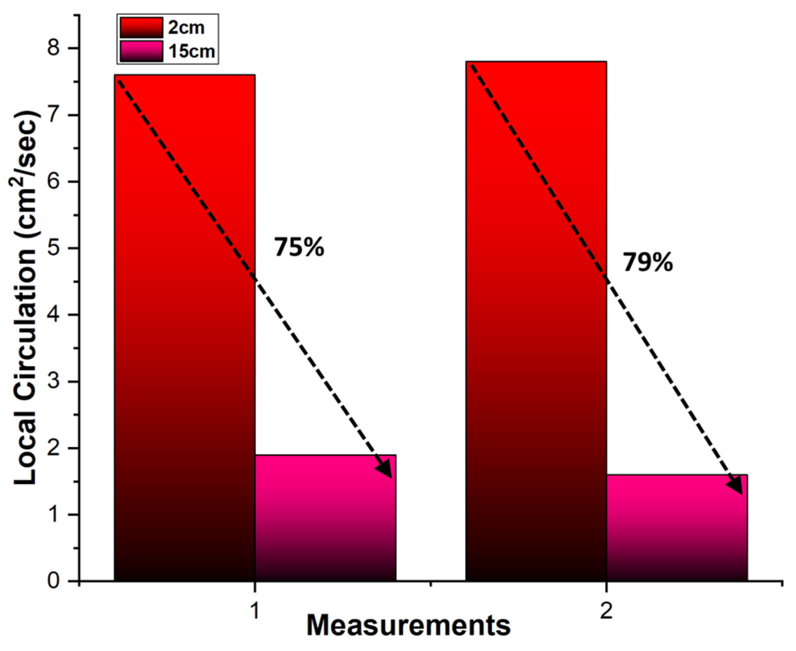
3.2. Circulation Flow Ring and Vortical Structures Inside the Flow Regimes

Steam was injected in this phase of the experiment, along with parallel flowing water, for time durations varying from 10–60 s. The data were acquired at 0–20 cm from the steam nozzle exit. It should be noted that there are a few points where the velocity fluctuations have shown repetitive behavior. The variations and fluctuations of velocity showed the most repetitive (6%) and dominant character at different points within this range. The vorticity distribution showed a decreasing trend as soon as the array of sensors was traversed away from the starting position, i.e., 0 cm. This decrease indicated a monotonic character, in general, all the way to the distance of 16–20 cm away from the exit of the nozzle; however, from this onward, the velocity fluctuations were represented by a wavy character. The decreasing trend shown by the time-averaged velocity fluctuations gives us clues as to the diffusive character of the steam-induced vortical ring at its periphery, where it entrains the surrounding fluid, giving birth to the comparatively higher fluctuations at the outer region within the co-currently flowing water. This can be seen in the plot of the fluctuating velocities in Figure 2a at the above-said distance. One important observation recorded within the region of the length segment of 12–18 cm is the weaker vorticity compared to the vorticity observed at the distance of 2.5 cm from the nozzle exit. Accompanying this, the circulation (Equation (2)) obtained for the core region is compared to the local circulation (Equation (3)) recorded along the downstream area using angular velocity distribution. It has been observed that the values of the circulation, even along the downstream area, are still more considerable than the values of the total circulation at the central core, as shown in Figure 2b. In addition to it, the dependence of the dimensionless diameter associated with the central circulation vortical structure was also obtained. The dimensions of the circulating ring were also estimated with the help of Equation (4), where the values of the reversal provide the indication of the opposite sign vorticity at the interface, as shown in Figure 2b. The results have shown that for all the injection time durations (10–60 s), the dependence of the circulating vortical structure was very weak at varying injection times. It was also confirmed that even the Reynolds number did not add any dominant effect on the diameter of the ring; this finding is in line with an earlier study [16].
The dependence of the length of the vortical circulation ring land diameter against the steam inlet pressure (5 bars) and the injection time was also determined. It was estimated by first assuming that the velocity (U), which was measured on an average basis at the exit of the steam nozzle, had a uniform distribution; the length (L) of the steam-induced vortical during the time duration (t) is given by the following relationship [17]:
Γ 0 = 1 2 0 t U d L
This is the simplest equation supporting the impulsive flow, yet it does not account for the effects imparted by the vorticity at the edges of the nozzle exit. It should also be noted that the length of the vortical circulation was measured with the help of Equation (3), whereas its diameter was measured with the help of Equation (2), and the negative values of the vorticity provided the information related to the approximate spatial positions where the interface between the surrounding fluid and the circular vortical ring existed.

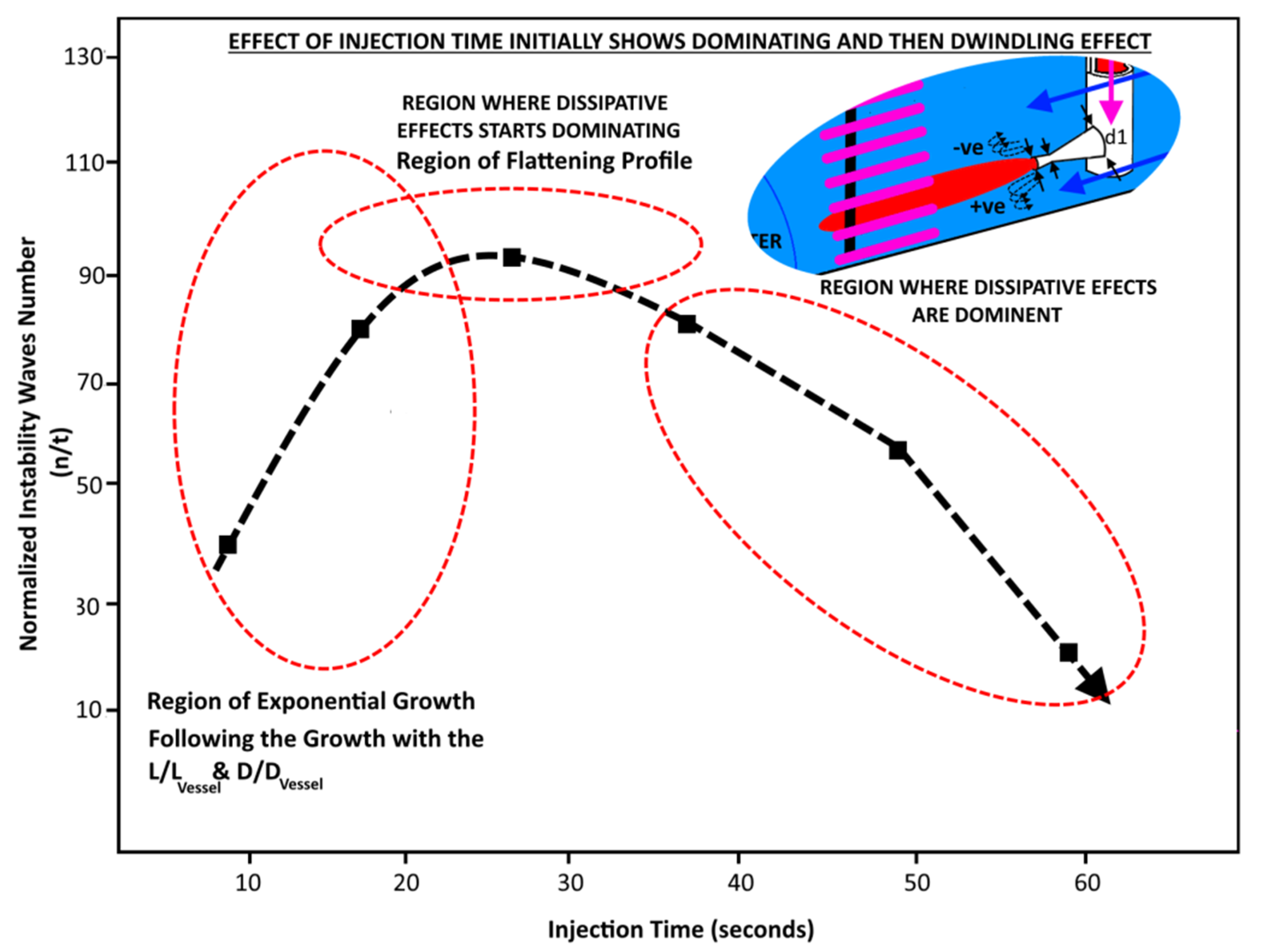
3.3. Effect of Injection Time on the Instabilities inside the Flow Regime

It should also be noted that when traversing the velocity sensors, flow instabilities were measured inside the flow, which remained dominant until the time when steam was injected into the water; the flow dissipated after the valve for steam injection was shut after the steam’s injection for a specified time period. The instabilities observed here are analogous to similar instances in earlier studies [18,19,20,21,22,23] with variations in steam injection duration or variations in Reynolds number. However, a few interesting trends in the instabilities’ wave number can be seen in Figure 3.
The wave number follows an almost exponential trend until the injection time of ~20 s before it smoothens along the horizontal. This curvy trend is observed in the time domain range of 20–30 s. It shows an increasing trend initially; however, afterwards, a sudden decreasing trend can be seen, which emphasizes the dominant role of the dissipative effects in the current flow regime. A straightforward reason for such a behavior is the instabilities that have first shown an increasing trend, which is consistent with the dimensions of propagation of the circulation of the vortical ring, which, afterwards, has been broken out, with the resultant profiles showing gradually flattening profiles due to the dissipative character under the action of such dissipative forces. Although the phenomena of the pulsating fluid injection into the water have been described by a number of studies (mostly visualization studies), here, in the current manuscript, we quantitatively discuss the effect of pulsating steam injections into the water on the flow regimes involving interactions between steam and water. It should also be noted that we accept the non-frozen nature of the data; however, on an average basis, the fluid regime has been characterized as much as we can. Asfar as the accumulative results are concerned, which can be drawn on the basis of the results discussed until now, it was found that for the core region, which emerged but remained attached to the nozzle exit, with the rise in the injection time, only a slight rise in its length was observed. However, the main core was responsible for giving birth to the forward rolling large vortical structures (which remained attached to the lip of the nozzle), with just a minor depressive flow profile (observations were guessed on the basis of the data from the HFA sensors) near the nozzle exit that was due to the sudden expansion of the steam jet as soon as it emerged from the nozzle exit. The steam’s jet injection into the water in a pulsating mode resulted in the formation of vortical structures with small values along the periphery of the jet, which had opposite signs on the upper and downward sides due mainly to the negative and positive gradients of the velocities along the horizontal and vertical directions, as shown by the inside picture in Figure 3.
The quantitative balance between the positive and negative vorticities across the steam–water interface in the upward and downward directions of the steam’s nozzle exit cannot be measured due to the lack of the present experimental capabilities to characterize the fluids from this point of view. However, on a generalized basis, it can be said that the balance may depend on the Reynolds number and on the duration of injection of the steam, and the suitable location for such a measurement could be the region in the vicinity of the nozzle exit. An earlier study [24] investigated the exact effect of the Reynolds number on the balance between the pulsating injection-induced positive and negative vorticities. However, further studies [17] conducted after that revealed that the correlations did not agree with the experimental measurements, even the earlier efforts [24] in which it was declared that the injected fluid rolls up in the forward direction; thus, the induced vorticity from various viscous processes at the nozzle exit resulted in underestimations in predicting the experimental data.
Although such efforts did not exactly predict the exact balance between the positive and negative vorticities, the basic physical phenomenon that can be used as a basis for modeling such a case cannot be simply denied as a whole since, in the region far from the injection point, the viscous dissipation will surely become dominant over inertial forces to break down large circulating structures.

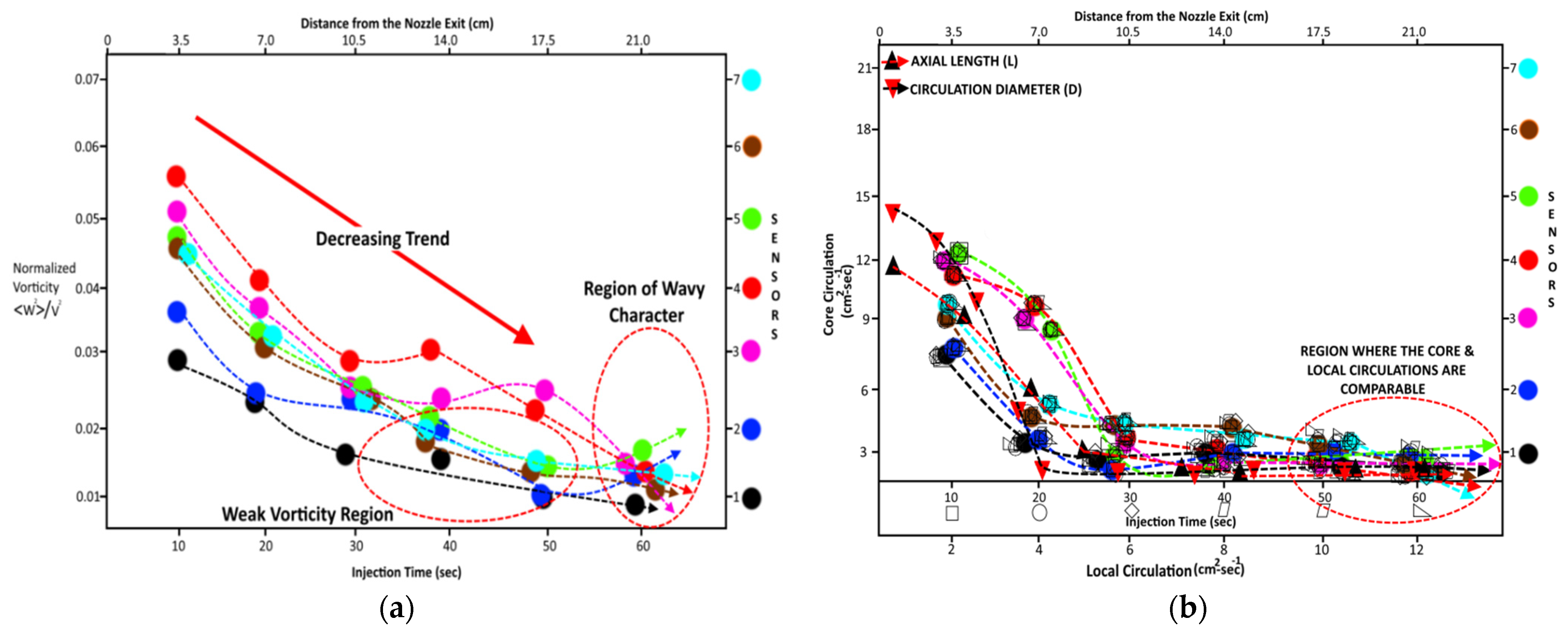
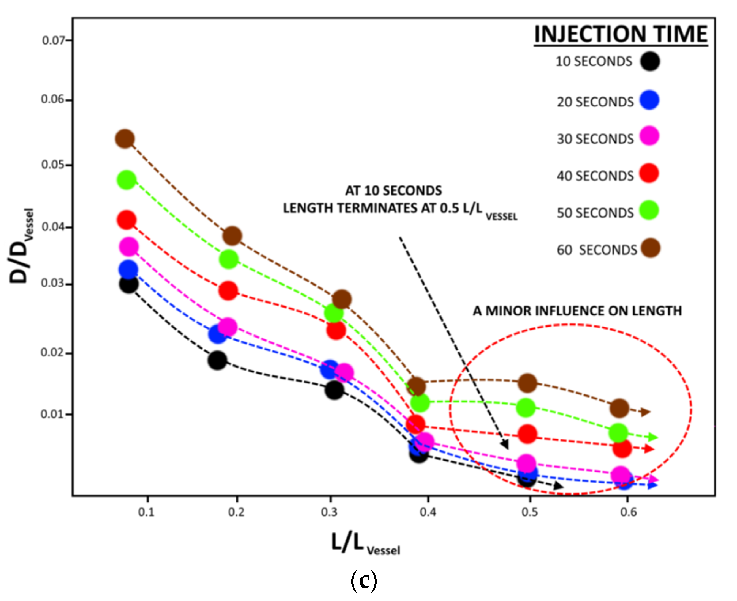
3.4. Flow Hydrodynamics in the Region Far from the Steam Nozzle

It has been observed in a number of studies [25,26,27,28,29] that the instabilities at the interface have lower amplitudes in the region near the nozzle exit that are transformed into larger and larger amplitude instabilities as soon as the steam propagates into the water. The amplitude of such instabilities, after a finite rise, breaks down into ring-like vortices that cause the interaction between the fluids at the interface. A possible reason for such behavior can be seen in earlier studies [19], where an imbalance between the axial wave number and the radial mode number was claimed [21]. According to the observations quoted in the given studies, the breaking of the outer core did not take place uniformly; rather, it occurred in the azimuthal direction with the formation of a net flow. It was further observed in another earlier study [30], which claimed the propagation of just a single wave along the central core and that the wave had a finite amplitude and a large axial velocity. Due to the large axial flow velocity, the central core wave in the far-off region had a profound effect on the regime, owing to the ring’s instability.
The measurements at the far region from the nozzle exit exhibited a non-frozen nature that depicted the highly fluctuating nature of the flow regime. The velocity fluctuations measured at the central core had smaller amplitudes than the velocity amplitudes at the periphery of the circulating region.
The main reason for this may be the higher axial mean velocities; fluctuations in the velocity are marginal compared to the mean values. Additionally, the interface appeared to be turbulent in the far region as well, and this was characterized due to the formation of the vortical structures, owing to the entrainment of the surrounding water. The variations in the magnitudes of the vorticities in the far region were relatively large due to the stronger interaction between the steam and the surrounding water. To fully understand the effects imparted by the vortices and the turbulence at the far region from the nozzle exit, the local circulations at two distances, i.e., 2 and 15 cm from the nozzle exit, were obtained (see Figure 4), which were then compared with the core local circulations at the distance of 2 cm. The local circulation was found to lose 75–79% of its circulation at a distance of 15 cm, as shown in Figure 4.

4. Conclusions

An experimental study was performed to highlight the hydrodynamics in a desuperheater vessel when pressurized pulsating steam is injected co-currently with slow-moving water in a cylindrical vessel. The velocity fluctuations associated with the steam–water mixture were obtained using an array of seven HFA sensors, traversed axially across the flow domain. The measurements obtained against the steam injection duration, varying from 10–60 s along the axial distance of 0–20 cm from the nozzle exit, showed a decreasing trend for time-averaged velocity fluctuations, which hinted at the diffusive character of the steam’s induced vortical ring at the periphery of the circulation associated with the entrained water, giving rise to comparatively higher fluctuations at the outer region of the ring. Within the length of 12–18 cm from the nozzle exit, the vorticity was weaker than the vorticity obtained at the distance of 2.5 cm from the nozzle exit. Additionally, the formation of the vortical structures, having small values along the periphery of the jet, was found; it had opposite signs on the upper and downward sides, mainly due to the negative and positive gradients of the velocities along the horizontal and vertical directions. Influences due to the vortices and turbulence at the far region from the nozzle exit were determined by determining the local circulations at 2 and 15 cm from the nozzle exit. The core local circulations at a distance of 2 cm from the nozzle exit were found to lose 75–79% of their circulation at a distance of 15 cm from the nozzle exit.

Author Contributions

Concept of the article, A.K. and K.S.; Methodology, P.A.T. and V.V.S.; Flow Measurements, P.A.T. and V.V.S.; Flow Variables Estimation, H.A.G., M.H.H.G. and A.H.A.; Investigation and Resources; A.R.H.R. and K.S.; Data Analysis, A.K., P.A.T. and V.V.S.; Draft Preparation, H.A.G., M.H.H.G. and A.H.A.; supervision, A.K. and K.S.; Formal Analysis and Writing—review & Editing: A.U.; Final Manuscript Preparation, A.K., P.A.T. and V.V.S. All authors have read and agreed to the published version of the manuscript.

Funding

The project was funded by the Deanship of Scientific Research (DSR) at Jazan University, Jazan, Kingdom of Saudi Arabia, under grant no. W43-063. The authors acknowledge DSR with thanks for technical and financial support.

Informed Consent Statement

Not applicable.

Data Availability Statement

Data will be available to the interested readers upon request.

Acknowledgments

The authors are thankful to the Russian Government and the Research Institute of Mechanical Engineering, the Department of Vibration Testing and Equipment Condition Monitoring, the Research Laboratory of Technical Self-Diagnostics and Self-Control of Devices and Systems, and the Department of Scientific and Innovative Activities, South Ural State University, Lenin prospect 76, Chelyabinsk, 454080, Russian Federation, for their support of this work through Act 211 of Government of the Russian Federation, Contract No. 02. A03.21.0011. The project was funded by the Deanship of Scientific Research (DSR) at Jazan University, Jazan, Kingdom of Saudi Arabia, under grant no. W43-063. The authors acknowledge DSR with thanks for technical and financial support.

Conflicts of Interest

The authors declare no conflict of interest.

References

  1. Nkomo, J.C. Energy and economic development: Challenges for South Africa. J. Energy South Afr. 2016, 16, 11. [Google Scholar]
  2. Rosas-Flores, J.A.; Rosas-Flores, D.; Gálvez, D.M. Saturation, energy consumption, CO2 emission and energy efficiency from urban and rural households appliances in Mexico. Energy Build. 2011, 43, 10–18. [Google Scholar] [CrossRef]
  3. Mahmoudi, M.; Fattahpour, V.; Roostaei, M.; Kotb, O.; Wang, C.; Nouri, A.; Sutton, C.; Fermaniuk, B. An Experimental Investigation into Sand Control Failure due to Steam Breakthrough in SAGD Wells. In Proceedings of the Society of Petroleum Engineers—SPE Canada Heavy Oil Technical Conference, CHOC 2018, Calgary, AB, Canada, 13–14 March 2018; Volume 2018. [Google Scholar]
  4. Australian Government, Infrastructure. 2010. Available online: www.infrastructure.gov.au (accessed on 14 August 2022).
  5. Aguilar, C.; White, D.J.; Ryan, D.L. Domestic Water Heating and Water Heater Energy Consumption in Canada; CBEEDAC: Edmonton, AB, Canada, 2005. [Google Scholar]
  6. Energy Efficiency Trends and Policies in the Household and Tertiary Sectors. An Analysis Based on the ODYSSEE and MURE Databases; Odyssee-MURE Project: Brussels, Belgium, 2015.
  7. Allouhi, A.; El Fouih, Y.; Kousksou, T.; Jamil, A.; Zeraouli, Y.; Mourad, Y. Energy consumption and efficiency in buildings: Current status and future trends. J. Clean. Prod. 2015, 109, 118–130. [Google Scholar] [CrossRef]
  8. Hepbasli, A.; Kalinci, Y. A review of heat pump water heating systems. Renew. Sustain. Energy Rev. 2009, 13, 1211–1229. [Google Scholar] [CrossRef]
  9. Jaisankar, S.; Ananth, J.; Thulasi, S.; Jayasuthakar, S.T.; Sheeba, K.N. A comprehensive review on solar water heaters. Renew. Sustain. Energy Rev. 2011, 15, 3045–3050. [Google Scholar] [CrossRef]
  10. Shukla, A.; Buddhi, D.; Sawhney, R.L. Solar water heaters with phase change material thermal energy storage medium: A review. Renew. Sustain. Energy Rev. 2009, 13, 2119–2125. [Google Scholar] [CrossRef]
  11. Chow, T.T. A review on photovoltaic/thermal hybrid solar technology. Appl. Energy 2010, 87, 365–379. [Google Scholar] [CrossRef]
  12. Ullah, A.; Khan, A.; Sanaullah, K.; Ghazwani, H.A.; Alexandrovich, T.P. Effects of External Oscillations on Cocurrently Flowing Steam–Water in Pipes. J. Vib. Eng. Technol. 2022, 2022, 1–13. [Google Scholar] [CrossRef]
  13. Linden, P.F. The interaction of a vortex ring with a sharp density interface: A model for turbulent entrainment. J. Fluid Mech. 1973, 60, 467–480. [Google Scholar] [CrossRef]
  14. Bhandari, P.; Prajapati, Y.K. Influences of tip clearance on flow and heat transfer characterstics of open type micro pin fin heat sink. Int. J. Therm. Sci. 2022, 179, 107714. [Google Scholar] [CrossRef]
  15. Maxworthy, T. Turbulent vortex rings. J. Fluid Mech. 1974, 64, 227–240. [Google Scholar] [CrossRef]
  16. Liess, C.; Didden, N. Experimente zum Einflußder Anfangsbedingungen auf die Instabilität von Ringwirbeln. ZAMM J. Appl. Math. Mech. Angew. Math. Mech. 1976, 56, T206–T208. [Google Scholar]
  17. Maxworthy, T. Some experimental studies of vortex rings. J. Fluid Mech. 1977, 81, 465–495. [Google Scholar] [CrossRef]
  18. Krutzsch, C.-H. {\ “U} about an experimentally observed appearance on vertebral rings during their translational movement in real liquids. Ann. Phys. 1939, 427, 497–523. [Google Scholar] [CrossRef]
  19. Maxworthy, T. The structure and stability of vortex rings. J. Fluid Mech. 1972, 51, 15–32. [Google Scholar] [CrossRef]
  20. Moore, D.W. A numerical study of the roll-up of a finite vortex sheet. J. Fluid Mech. 1974, 63, 225–235. [Google Scholar] [CrossRef]
  21. Widnall, S.E.; Bliss, D.B.; Tsai, C.Y. The instability of short waves on a vortex ring. J. Fluid Mech. 1974, 66, 35–47. [Google Scholar] [CrossRef]
  22. Widnall, S.E.; Sullivan, J.P. On the stability of vortex rings. Proc. R. Soc. Lond. A Math. Phys. Sci. 1973, 332, 335–353. [Google Scholar] [CrossRef]
  23. Liess, C.; Didden, N. Experiments on the influence of the initial conditions on the instability of ring vertebrae. ZAMM J. Appl. Math. Mech. Z. Appl. Math. Mech. 1976, 56, T206–T208. [Google Scholar]
  24. Moore, D.W.; Saffman, P.G. Axial flow in laminar trailing vortices. Proc. R. Soc. Lond. A Math. Phys. Sci. 1973, 333, 491–508. [Google Scholar] [CrossRef]
  25. Afrasyab, K.; Sanaullah, K.; Takriff, M.S.; Zen, H.; Fong, L.S. Inclined Injection of Supersonic Steam into Subcooled Water: A CFD Analysis. Adv. Mater. Res. 2013, 845, 101–107. [Google Scholar] [CrossRef]
  26. Khan, A.; Sanaullah, K.; Takriff, M.S.; Zen, H.; Rigit, A.R.H.; Shah, A.; Chughtai, I.R. Numerical and experimental investigations on the physical characteristics of supersonic steam jet induced hydrodynamic instabilities. Asia-Pacific J. Chem. Eng. 2016, 11, 271–283. [Google Scholar] [CrossRef]
  27. Khan, A.; Sanaullah, K.; Haq, N.U. Development of a Sensor to Detect Condensation of Super-Sonic Steam. Adv. Mater. Res. 2013, 650, 482–487. [Google Scholar] [CrossRef]
  28. Khan, A.; Sanaullah, K.; Sobri Takriff, M.; Hussain, A.; Shah, A.; Rafiq Chughtai, I. Void fraction of supersonic steam jet in subcooled water. Flow Meas. Instrum. 2016, 47, 35–44. [Google Scholar] [CrossRef]
  29. Khan, A.; Sanaullah, K.; Takriff, M.S.; Zen, H.; Fong, L.S.; Shah, A. CFD Based Hydrodynamic Parametric Study of Inclined Injected Supersonic Steam into Subcooled Water. In Proceedings of the International Engineering Conference, Energy and Environment (ENCON 2014), Beijing, China, 26–27 June 2014. [Google Scholar]
  30. Leibovich, S.; Randall, J.D. Solitary waves in concentrated vortices. J. Fluid Mech. 1972, 51, 625–635. [Google Scholar] [CrossRef]
Figure 1. An experimental setup of the desuperheating vessel.
Fluids 07 00313 g001
Figure 2. (a). Normalized vorticity along the flow channel. (b). Core vs. central circulation of steam–water flow. (c). Dependence of length and diameter on the injection time.
Fluids 07 00313 g002aFluids 07 00313 g002b
Figure 3. Effect of injection time on normalized instability wave numbers.
Fluids 07 00313 g003
Figure 4. Comparison of local circulations at different locations along the axial axis.
Fluids 07 00313 g004
Publisher’s Note: MDPI stays neutral with regard to jurisdictional claims in published maps and institutional affiliations.

