Article

Modal Decomposition Techniques: Application in Coherent Structures for a Saccular Aneurysm Model

1
Department of Soils and Water Systems, University of Idaho, Moscow, ID 83844, USA
2
Department of Mechanical Engineering, University of Idaho, Moscow, ID 83844, USA
*
Author to whom correspondence should be addressed.
Fluids 2022, 7(5), 165; https://doi.org/10.3390/fluids7050165
Submission received: 1 April 2022 / Revised: 26 April 2022 / Accepted: 28 April 2022 / Published: 9 May 2022
(This article belongs to the Special Issue Coherent Structures in Fluid Mechanics)

Abstract

:
Aneurysms are localized expansions of blood vessels which can be fatal upon rupture. Studies have shown that aneurysm flows exhibit complex flow phenomena which consist of single or multiple vortical structures that move within the flow cycle. Understanding the complex flow behaviors of aneurysms remain challenging. Thus, the goal of this study is to quantify the flow behavior and extract physical insights into aneurysm flows using advance data decomposition methods, Proper Orthogonal Decomposition (POD) and Dynamic Mode Decomposition (DMD). The velocity field data were obtained by performing 2D Particle Image Velocimetry (2D PIV) on the mid-plane of an idealized, rigid, saccular aneurysm model. The input flow conditions were set to R e p = 50 and 150 for a fixed α = 2 using a precisely controlled piston pump system. POD was used to quantify the spatial features of the flows, while DMD was used to obtain insight on the dynamics. The results obtained from POD and DMD showed the capability of both methods to quantify the flow field, with the modes obtained providing different insights into the flow evolution in the aneurysm. The curve-fitting step of the POD time-varying coefficients, and the appropriate selection of DMD modes based on their energy contribution, allowed the mathematical flow models from POD and DMD to reconstruct flow fields at any given time step. This can be used for validation of numerical or computational data.

1. Introduction

Flows in intracranial aneurysms exhibit complex behavior with spatial and temporal characteristics. Research studies have reported that flows in aneurysms can consist of a single vortical structure, which can be stationary or can move within a flow cycle. Other studies have shown the presence of multiple vortical structures that become unstable in the cardiac cycle. The presence of different vortical structures and their behavior have made understanding aneurysm flows challenging. Understanding these large-scale structures and their behavior would allow researchers to learn about aneurysm pathophysiology (i.e., initiation, growth, and rupture processes), and further lead to better treatment options of aneurysms. To obtain physical insight about complex flows, researchers have begun using advanced data analysis tools such as Proper Orthogonal Decomposition (POD) and Dynamic Mode Decomposition (DMD) to extract key features about their data set.
Recent years have shown increased use of POD and DMD to obtain the energetic or dynamical sense of the flow field. POD has been the method of choice by researchers to optimally deduce coherent structures from the flow field. It is an algorithm used to decompose a data set and extract highly energetic structures or spatial ’modes’ from it. Its optimality feature has allowed researchers to capture the dominant features of the data using the fewest amount of modes. POD has found its use in aneurysm flows such as quantifying spatial complexity [1], improving numerical simulations [2], comparing time-varying three-dimensional hemodynamic data [3], and quantifying the impact of flow behavior [4]. DMD, on the other hand, provides a modal decomposition to capture the flow dynamics (i.e., the spatio-temporal behavior of the coherent structures) in the flow field, which POD is not able to provide. This is important in understanding the flow behavior in an aneurysm, particularly for the unsteady flows. The decomposition method gives dynamic modes that are characterized by their frequencies and corresponding growth/decay rates. DMD allows researchers to understand the flow field and its dynamics with the DMD modes. DMD has been applied to previous aneurysm studies to reveal hidden low-dimensionality in blood-flow data [5], to identify the energetic modes of the inflow jet in patient-specific models [6], to compare POD and DMD modes for a flow in a cerebral aneurysm model [7], and to identify the impact of inflow conditions [8]. Depending on the analysis approach used by the researcher, POD and DMD can provide a low-order flow representation of flow evolution using appropriately selected modes and coefficients.
The previous studies on aneurysms show the potential of using advanced data decomposition methods to analyze complex aneurysm flows in detail. The presence of complex flow structures have encouraged the use of POD and DMD to quantify flow characteristics, and to attempt to create a mathematical model in predicting their behavior. However, there remains a challenge in utilizing the information given by POD and DMD to obtain physical insight to the flow. The present study, therefore, aims to connect the observed flow behavior in an idealized, rigid, and saccular aneurysm model with the captured modes and information from POD and DMD. In this investigation, the decomposition methods were used to quantify the flow in an aneurysm with a wide neck opening. The flow field data were obtained using Particle Image Velocimetry (PIV) and inflow scenarios were controlled using a precise piston pump system. For this study, the inflow scenario were characterized by Reynolds number ( R e p ) and Womersley number ( α ), from R e p = 50,150 and fixed α = 2 , respectively. The results from POD and DMD showed that both methods are capable of quantifying the flow behavior, and the interpretation of the modes are dependent on the decomposition method used. Furthermore, POD and DMD can provide valuable insight to the flow and provide accurate representation of the flow field using an appropriate number of modes.
The manuscript is organized such that the background study is first discussed. This is followed by the experimental setup, analysis approach, and results and discussion sections. Lastly, the summary of findings in this study is presented.

2. Background

There are many different types of flows that can be observed in nature or in engineering systems. Simple flows such as flow over a flat plate or a pipe flow can be justified using using basic physics and engineering principles [9]. Others are more complex, such as cavity flows [10] and artery flows [11], whose multi-factorial components encompass geometry, biology, material and fluid compositions, and chemistry to name a few. Understanding different flows, simple or complex, is important, as it translates to efficient engineering designs, increased engineering productivity, reduced operational costs, increased lifetime of components, and reduced catastrophic events leading to loss of lives. However, understanding complex flows can be challenging as they require extensive knowledge, resources, and ingenuity.
Aneurysms are examples of artery flows which exhibit complex flow phenomena. Aneurysms are an abnormal localized expansion of a weakened blood vessel, and researchers have classified them based on their shape or location. Typical shapes of aneurysms are fusiform or saccular [12], and they are found in the aorta (called abdominal aortic aneurysms) [13], in the portion of the aorta through the chest area (called thoracic aortic aneurysms) [14], and in the brain (called cerebral or intracranial aneurysms) [15]. Meanwhile, aneurysms, when left untreated or undetected, can impact blood circulation as well as lead to thrombosis and blood clots [16,17,18]. A ruptured aneurysm can cause stroke or internal bleeding, which are life-threatening. Current aneurysm treatment options are limited to observation, clipping, or placement of coils or stents [15]. However, each treatment method has their associated risks, such as patient discomfort after surgery, recurrence, and infections. Access to the aneurysm during operation also poses a challenging task of managing and assessing aneurysms [15].
There is an exhaustive list of studies that have made efforts to provide explanations on different aspects of aneurysm behavior, including initiation, growth, and rupture, and to develop assessment and treatment methods for patients accordingly. For instance, earlier studies used aneurysm size to quantify likelihood of rupture [19,20]. With advancements in technology and computational capabilities, other studies used non-dimensional geometrical characterization of different sizes and shapes to identify aneurysms with low and high risk of rupture [21,22,23]. A few studies have focused on hemodynamics, using computational [24,25,26] and experimental [27,28,29,30] approaches, and identified hemodynamics as playing an important role in aneurysm behavior, particularly in aneurysm progression and rupture. Although these studies have shown the presence and complex nature of large-scale flow structures in aneurysm flows, focus on these flow structures on hemodynamic parameters has surprisingly not been investigated in detail. This includes investigations focusing on different geometries and inflow conditions and the ability to create mathematical models to accurately predict large-scale flow behavior.
Despite significant progress in the overall understanding of aneurysms, predictability of their flow behavior and its contribution to aneurysm pathophysiology in the presence of unsteady inflow conditions still requires further investigation. For example, large-scale flow structures in aneurysms are complex and their behavior remains to be understood. Flow structures in aneurysms can consist of a single recirculating structure that can remain stationary or move throughout the cardiac cycle. Other flow structures may contain one or more recirculating regions that remain stationary or become unstable during the cardiac cycle. These different large-scale flow patterns have been shown in previous studies [26,31,32,33,34]. For example, Budwig et al. [31] reported that for steady flow in AAAs, the flow field is characterized by a jet of fluid surrounded by a recirculating vortex. Fukushima et al. [32] reported that in pulsatile flow in AAA, vortices appeared and disappeared at different phases in the cardiac cycle. During this time, the center of the vortex moved from upstream to the downstream side of the aneurysm. Yu and Zhao [33] reported that for steady flow of their sidewall aneurysm studies, a large recirculating vortex occupies the entire aneurysm sac. Le et al. [34] described in their numerical studies that for sidewall aneurysm models, the vortex structure can remain stable or move within the aneurysm sac. The observed flow complexity and presence of large-scale structures have motivated the current study to further investigate this behavior through the use of advanced data analysis methods.
Modal decomposition methods have been growing in popularity as data analysis tools to aid researchers in gaining an understanding of complex flows. They are used to extract physically important features or modes in the flow field. These modes or spatial features are associated with characteristic values which represent either the energy levels or frequencies and growth rates [35]. Examples of these decomposition methods are POD, which provides modes that are optimally determined to capture the most possible energy in the fewest amount of modes [36,37,38], and DMD, which provides modes that are defined by a single frequency of oscillation and growth behavior [39,40]. Review articles from Taira et al. [35,41] and Rowley and Dawson [42] provide an excellent broad overview of different modal decomposition techniques as well as applications of these methods to flows over a cylinder, airfoil, and rectangular cavity.
POD and DMD to aneurysm flows have been applied to velocity data obtained either from experimental [4,8,43] or computational fluid dynamics (CFD) investigations [1,2,3,5,6,7]. A few of these studies have used these modal decomposition techniques as a means to improve computational simulations, to quantify different flow regimes. For example, Byrne et al. [1] used POD on CFD simulations to classify the hemodynamics of patient-specific intracranial aneurysm geometries according to spatial complexity and temporal stability using parameters derived from vortex core lines. The results from their study found that ruptured aneurysms have complex and unstable dynamics, while unruptured aneurysms have simple and stable dynamics. Daroczy et al. [2] used POD to determine the spectral entropy of different flow regimes, and quantified the flow state between laminar, transitional, or turbulent regimes for use with their hybrid simulations. Janiga [3] used POD for comparison of different time-varying three-dimensional hemodynamic data and showed the ability of POD to reduce the complexity of the time-dependent data for quantitative assessment. Yu et al. and Yu and Durgesh [4,43] used POD to investigate impact of inflow conditions and different models. Their work highlighted the differences and similarities in the flow behavior through the POD modes and coefficients. With DMD studies, Habibi et al. and Le [5,6] used DMD to study flow behavior in patient-specific aneurysm models. Arzani and Dawson [7] have shown the potential of POD and DMD in cardiovascular research using a simple CFD of an idealized aneurysm model. Yu and Durgesh [8] used DMD to obtain insights on the dynamics in an aneurysm model at different inflow scenarios. Their work showed the impact of R e and α on the dynamical modes. These initial studies have provided valuable insight and motivation to researchers on how these modal decomposition methods can be used in analyzing complex aneurysm flows.
The existing body of knowledge about aneurysms has shown that they are a widely studied fluid dynamics problem, and researchers have attempted to answer fundamental questions on aneurysm behavior with different levels of success. The advancements in experimental and computational methods have allowed researchers to look at the aneurysm problem in greater detail than before, and enabled them to gain deeper insights into the flow dynamics of aneurysms using advanced analysis methods. However, additional work is still needed to expand the current knowledge on aneurysm flows, particularly in characterizing flow structures at different inflow conditions and their influence on the aneurysm hemodynamics. There is still a lack of comprehensive experimental studies that captures these large-scale flow structures and quantify their importance to the overall flow dynamics. Understanding and capturing these behaviors will allow researchers to create a mathematical description of the flow, which can be used to predict or control the flow in aneurysms. As a step in this direction, the present study aims quantify an aneurysm flow with the help of advanced decomposition methods such as POD and DMD. These methods can provide information that a researcher may need to understand the flow.

3. Experimental Setup

This section provides details of the experimental setup used for this study. First, a brief description of the aneurysm model will be provided. Details of the PIV setup and the pump used for this investigation will be discussed.

3.1. Aneurysm Model and Fluid

Figure 1 shows the schematic for the aneurysm used in this investigation. The aneurysm used is a straight, rigid, idealized, and saccular model. The figure also shows the critical features of the model. The design features a cylindrical pipe with a long entry length to let the fluid reach a fully developed state before entering the aneurysm [11], and a return section to dissipate the flow disturbances. The bulge was spherical in shape, with maximum aneurysm sac diameter and neck diameter of 13.87 mm.
The aneurysm design in Figure 1 was fabricated at a professional glass shop using borosilicate glass. The glass material was selected as the surface is hydraulically smooth, and the index of refraction can be matched with a commercially available fluid. The refractive index matching between the model and fluid allowed optical access to the flow field in the aneurysm geometry. After fabrication of the aneurysm shape, the model was inspected and dimensions were verified using a calibrated image plane. The inspection also showed the aneurysm entrances (i.e., neck) to be smooth.
The current study used aqueous glycerin to match the index of refraction of the aneurysm model. Glycerin was chosen for its availability and known fluid properties [44,45]. Furthermore, the fluid was successfully used in previous investigations [4,30,32,46,47,48] for aneurysm studies. The current study used an aqueous mixture of 60:40 by volume which had a density of ρ f = 1168.3 kg/m 3 and a kinematic viscosity of ν f = 1.453 × 10 5 m 2 /s. The characteristic length and velocity scales in the study were used to match the R e p and α [49] in the human cerebral circulatory system [11,26,34,50,51].

3.2. Velocity Field Measurements

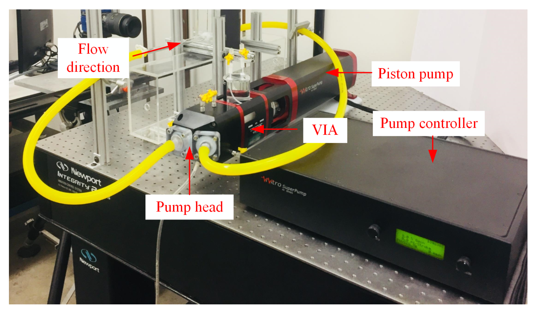
2D Particle Image Velocimetry (2D PIV) was used to the acquire velocity fields in the aneurysm model. Figure 2 shows the components of the experimental setup which consisted of the PIV system, flow loop system, and the pump system. The PIV system had a 200 mJ Nd:YAG double-pulsed laser which can pulse at 15 Hz. The system also had an 8 MP CCD camera with a macro lens attached to focus on the aneurysm region. Calibration was performed prior to PIV measurements, which yielded ≈0.012 mm/pixel spatial resolution and a field of view of 32 mm × 20 mm. Sheet optics were used to create a laser sheet thickness of 1 mm at the focal point.
The flow loop was seeded with silver-coated, neutrally buoyant, hollow glass spheres, 9–13 μm in diameter. Due to the difference in velocity magnitude in the pipe and aneurysm sac region, the field of view was divided into sub-regions, namely pipe, and sac. This approach allowed us to properly select the time between the PIV image pairs for each sub-region, and in turn, to capture the flow structures. PIV images were then set using a camera frame rate of 5 Hz which allowed us to capture different phases of the flow cycle. For post-processing, DaVis software was used to estimate the velocity flow field. Cross-correlation, multi-pass analyses with 50% overlap and final interrogation window of 32 × 32 pixels was used. The resulting settings yielded ≈11,070, and 1432 velocity vectors in the pipe and sac regions, respectively.

3.3. Pump System

R e p and α were the inflow parameters used to match and simulate the conditions in the human circulatory system. These inflow parameters were precisely controlled with a ViVitro Labs Inc. SuperPump system. The pump system consisted of a pump head, controller, and a Viscoelastic Impedance Adapter (VIA) which facilitated the movement of the fluid into the aneurysm region. The pump head featured spring-loaded disc valves that rectified the waveform signal coming from the pump controller. This feature was important as it mimicked the flow condition typically found in the human circulatory system. The pump controller provided the signal that the piston pump followed. Lastly, the VIA isolated the working fluid (i.e., glycerin solution) and the piston fluid. The VIA functioned as a damper to produce smooth pressure changes in the flow loop.
For this investigation, piston stroke lengths of 10 mL–30 mL and pump frequency of 0.4 Hz were used. The pump frequency setting of 0.4 Hz corresponded to α = 2 condition. The α = 2 condition was selected as it represented a quasi-steady flow regime with a known solution [52], and the value was within the values typically found in the human circulatory system [11,26,34,50,51]. For this study, a well-behaved sinusoidal signal was selected for the piston to follow. The other half of the waveform signal was rectified as a result of the disc–valve design.
The PIV and pump systems were synchronized to correlate the flow cycle and the PIV images. This was set by using a separate data acquisition system that simultaneously acquired the PIV trigger signal and piston information. The information acquired from the synchronization step was then used for POD time-varying coefficient analyses.

4. Approach

4.1. Proper Orthogonal Decomposition

POD is a method that decomposes the flow field into a set of modes or basis functions that are optimal in describing the flow field in a kinetic energy sense. The combination of the modes obtained along with corresponding coefficients thus provide a description of the flow field. Lumley [36], Sirovich [53], Berkooz et al. [37], and Holmes et al. [38] provide an excellent and rigorous mathematical description of the method to gain insight on complex fluid behavior. For this study, a few of these mathematical steps are shown (see [38] for detailed information).
The goal of POD is to find a set of functions that optimally (i.e., with fewest amount of functions or modes) describes the data set in the form [36,37,53]
U ( x , y , t ) = i = 1 N a i ( t ) Ψ i ( x , y ) ,
where U ( x , y , t ) is a velocity field, a i ( t ) is the time-varying coefficient of the ith basis function ( Ψ i ( x , y ) ) at some time t, and N is the number of modes. The basis functions are determined by maximizing the averaged projection of the velocity field U ( x , y , t ) onto Ψ i ( x , y ) . Mathematically, this is shown as [36,37,53]
m a x Ψ L 2 | U ( x , y ) , Ψ 2 | Ψ 2 ,
where | . | denotes the modulus, . is the ensemble average, . represents the inner product and . denotes the L 2 norm. The optimization problem in Equation (2) can be solved using calculus principles, which reduces to an Euler–Lagrangian equation shown as [54,55]
Ω x y U ( x , y ) U ( x , y ) Ψ ( x , y ) d x d y = λ Ψ ( x , y ) ,
where Ω x y is the domain of interest, U ( x , y ) U ( x , y ) is the spatial correlation of the velocity field, ⊗ is the tensor product, and λ is the energy associated with each POD mode. The formulation in Equation (3) can be further simplified and can be shown as an eigenvalue problem [36,37,53,54,55]
R Ψ ( x , y ) = λ Ψ ( x , y ) ,
where R is the kernel of the POD formulation, i.e., the spatial velocity correlation matrix that results from the definition of velocity vector tensor product. The eigendecomposition of Equation (4) yields eigenvectors (i.e., POD modes) related to the u and v components of velocity (i.e., ψ u u ( x , y ) and ψ v v ( x , y ) ), and eigenvalues ( λ ) which contained the energy in the POD modes. Lastly, the time-varying coefficients a i ( t ) are obtained by projecting the original velocity fields U ( x , y , t ) on to each of the POD modes, given as [54,55]
a i ( t ) = U ( x , y , t ) , Ψ i ( x , y ) .
The obtained time-varying coefficients ( a i ( t ) ) and POD modes ( ψ u u ( x , y ) and ψ v v ( x , y ) ) can then be used to create a low-order reconstruction of the flow field using Equation (1).
POD was implemented in-house using MATLAB. For this experimental scenario, 2000 PIV images were acquired spanning several minutes. The average velocity flow field was removed from the inflow condition in order to capture the POD modes based on the flow fluctuations in the data set. Next, the POD implementation in this study used an approach similar to Durgesh and Naughton [54] that couples the u and v components of velocity. This approach allowed for capturing the flow structures dependent on these components of velocity. The POD kernel then (i.e., R ) was determined using auto and cross correlations of u and v components of each velocity field. This resulted in a POD kernel of ∼2924 × 2924 elements. The eigendecomposition of R yielded the eigenvalues (i.e., λ i ) and POD modes (i.e., Ψ u u i ( x , y ) and Ψ v v i ( x , y ) ). The eigenvectors were the used to determine a i ( t ) using Equation (5), while the flow field reconstruction used Equation (1).

4.2. Dynamic Mode Decomposition

DMD is a method that decomposes time-resolved data into modes that are characterized by their frequencies and decay/growth rates. The combination of the modes determined from DMD can represent the dynamics in the data set. The mathematical formulation and review of DMD are provided by several authors [35,40,41,56,57]. Here, we note that DMD is a developing method, and there have been numerous variations of the technique [40,57,58,59,60,61]. The DMD approach used in this study is shown in the next few paragraphs.
We consider a data matrix D which contains consecutive snapshots of the instantaneous flow field { U 1 U 2 U m } separated by a time step Δ t [60]
D = { U 1 U 2 U m 1 } R n x m .
A second data matrix D is defined such that the data set D is shifted forward in time by an amount Δ t , where [60]
D = { U 2 U 3 U m } R n x m .
The snapshots U j and U j + 1 can be related by a coefficient A (i.e., U j + 1 = A U j ) where a linear mapping is assumed to relate the two snapshots. By doing this, the data sets D and D can be related with the operator A and can be written as [60]
D = A D .
Equation (8) relates the two matrices D and D by determining a best-fit linear operator A. The matrix A can be seen as a linear mapping matrix that connects the velocity field at time t to the velocity field at time t + Δ t . The eigenvalues and eigenvectors obtained from A thus contain the dynamics of the flow field. However, the matrix A is not directly computed due to the large size of the matrices D and D . A pre-processing step suggested by Schmid [40] allows capturing similar dynamics of A at a lower-dimensional subspace. This pre-processing step uses singular value decomposition (SVD) and similarity transformation applied to Equation (8), shown as [40]
Υ * A Υ = Υ * D V Σ 1 A ˜ .
The formulation in 9 shows the objective of DMD. DMD aims to find a low-order approximation of A with A ˜ . SVD provides robustness of the method, as eigenvalues and eigenvectors of A ˜ approximate the eigenvalues and eigenvectors of A via similarity transformation. With this in mind, the eigenvalues of A ˜ (i.e., λ i ) provide information on the growth/decay as well as frequency oscillations of each dynamic mode [40]. The real part of each eigenvalue ( g i ) represents the growth/decay, while the imaginary part ( f i ) contains the frequency for each dynamic mode. They can be determined using a logarithmic mapping of the eigenvalue using the equation [35,40]
g i = l o g ( | λ i | ) / ( 2 π Δ t ) ,
and
f i = λ i / ( 2 π Δ t ) .
where denotes the phase angle of λ i . The DMD modes ( Φ ) are obtained through the projection of the eigenvectors ( W ) of A ˜ on the vector space Υ . This is shown as [40]
Φ = Υ W .
The POD modes are contained in the vector space Υ [40] and have flow structures at multiple frequencies. The flow field snapshots s i at time t (i.e., U i ) can be reconstructed using the superposition of the DMD modes Φ , DMD eigenvalues Λ , and corresponding DMD amplitudes β , given as [57]
U i = k = 1 r ϕ k exp [ ( l o g ( λ k ) / Δ t ) t ] β k .
The low-order flow reconstruction shown in Equation (13) now provides information on flow field containing structures at different frequencies. The flow behavior representation can contain only the large-scale structures by selecting low frequencies to approximate the flow field. Equation (13) requires the contribution of the modes (i.e., β ) which can be determined using the optimal vector approach. This is given as [60]
β = ( ( W * W ) ( V a n d V a n d * ¯ ) ) 1 d i a g ( V a n d V Σ * W ¯ ) .
Equation (14) is a result of the optimization problem finding the minimum β values that best approximate s 1 using Equation (13) (see [60] for details). Here, the overline in Equation (14) is the complex conjugate of a vector, ∘ is an element-wise multiplication of matrices, diag of a vector is a diagonal matrix, with the main diagonal containing the elements of the given vector, and diag of a matrix is a vector containing the main diagonal of the given matrix. Lastly, the V a n d is the Vandermonde matrix which contains the eigenvalues λ i .
The DMD implementation is developed in-house using MATLAB. Prior to using DMD on the data set, the time-averaged component of the flow is not removed, and DMD is performed over five phase-averaged cycles in the flow evolution. The typical calculation processing for DMD analysis is approximately a few minutes. The obtained DMD modes, eigenvalues, and amplitudes are then used to create a low-order flow field using Equation (13).

5. Results

This section provides discussion of results to achieve the current objective of the paper. The POD and DMD modes were first presented here to highlight the energetic and dynamic features of the flow. The POD and DMD energy results were discussed next to elucidate the contribution of the modes. Lastly, the low-order reconstruction results were then presented to show how POD and DMD can capture the flow behavior using selected modes. The results are presented such that each section contains important information provided by each method.

5.1. POD and DMD Modes

The mode results are first presented here as they provide information on the large-scale flow features for each inflow scenario. The POD modes are the eigenvectors ( Ψ i ( x , y ) ) of the POD kernel ( R ) that are obtained using Equation (4). When combined together, POD modes optimally describes a given flow field with the first few modes. Furthermore, the modes are mathematical descriptions of the spatial flow structures present in the aneurysm. The modes were presented in order of importance, capturing the fluctuating kinetic energy in the flow. DMD modes are eigenvectors ( Φ ( x , y ) ) which also provide mathematical descriptions of the flow structures. The DMD modes are obtained using Equation (12) with each mode now associated with a given frequency and growth rate. For this discussion, the modes of POD and DMD were compared to identify the information provided by each method.
The first five POD modes ( Ψ i ) for R e p = 50 are shown in Figure 3a–e. The modes are presented as vector representation for clarity of captured spatial structures. The obtained POD modes are real due to the positive–definite matrix formed from the POD kernel ( R ), are orthogonal to each other, and individually contain a percentage of the total fluctuating kinetic energy of the flow field. Thus, POD modes present unique spatial features in the flow which can influence the overall flow field. The POD mode results showed that the order of these modes (i.e., Ψ 1 to Ψ 5 ) represents the presence of vortical structures at different locations in the aneurysm. This may provide information on the locations of the vortical structures at different time instances in the flow. Here, we note that the POD modes along with their coefficients are needed to be combined together to obtain an overall representation of the flow field for each R e p scenario. Thus, each POD mode result by itself can challenging to interpret as it does not provide a good sense of the large-scale behavior of the flow field. Furthermore, each POD mode may contain flow structures with different frequency information. This can be important insight on the temporal behavior of flow structures and their growth or decay in time.
The impact of changing R e p can be seen through the change in the obtained mode shapes as shown in Figure 4a–e for R e p = 150 . The mode shapes for this R e p scenario showed a different set of spatial structures than R e p = 50 . The first two modes were observed to be similar to the first two modes of R e p = 50 (i.e., Figure 3a,b), while modes three to five for both R e p scenarios showed a different order of spatial structures. This highlights the changes in the flow trend (i.e., change in vortical structure location in the aneurysm). Though POD modes for both R e p scenarios provide information on the spatial structures and their energetic contribution to the flow, the dynamics of the flow structures are not provided with POD (i.e., their growth or decay behavior during the flow evolution). This information can be important in understanding the impact of large-scale structures on the overall trend of the flow field.
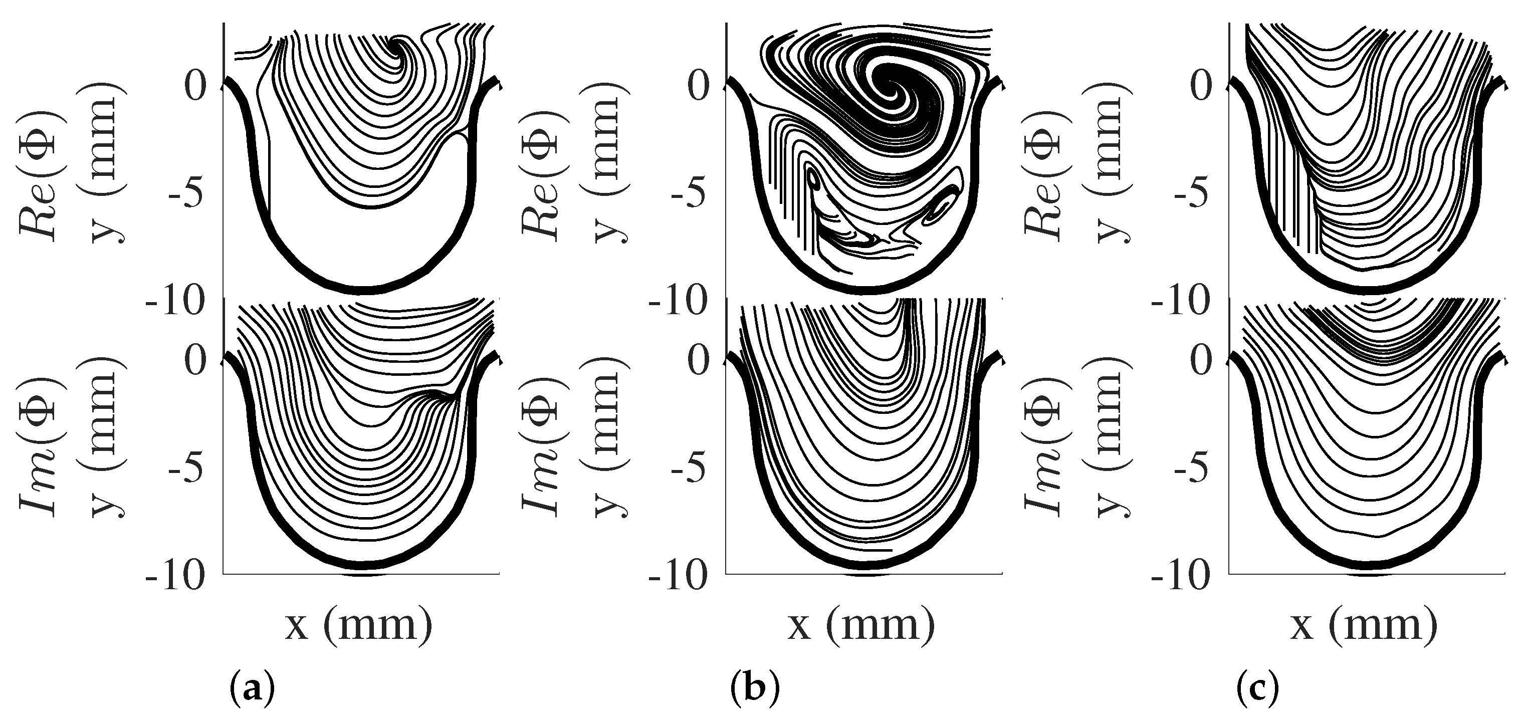
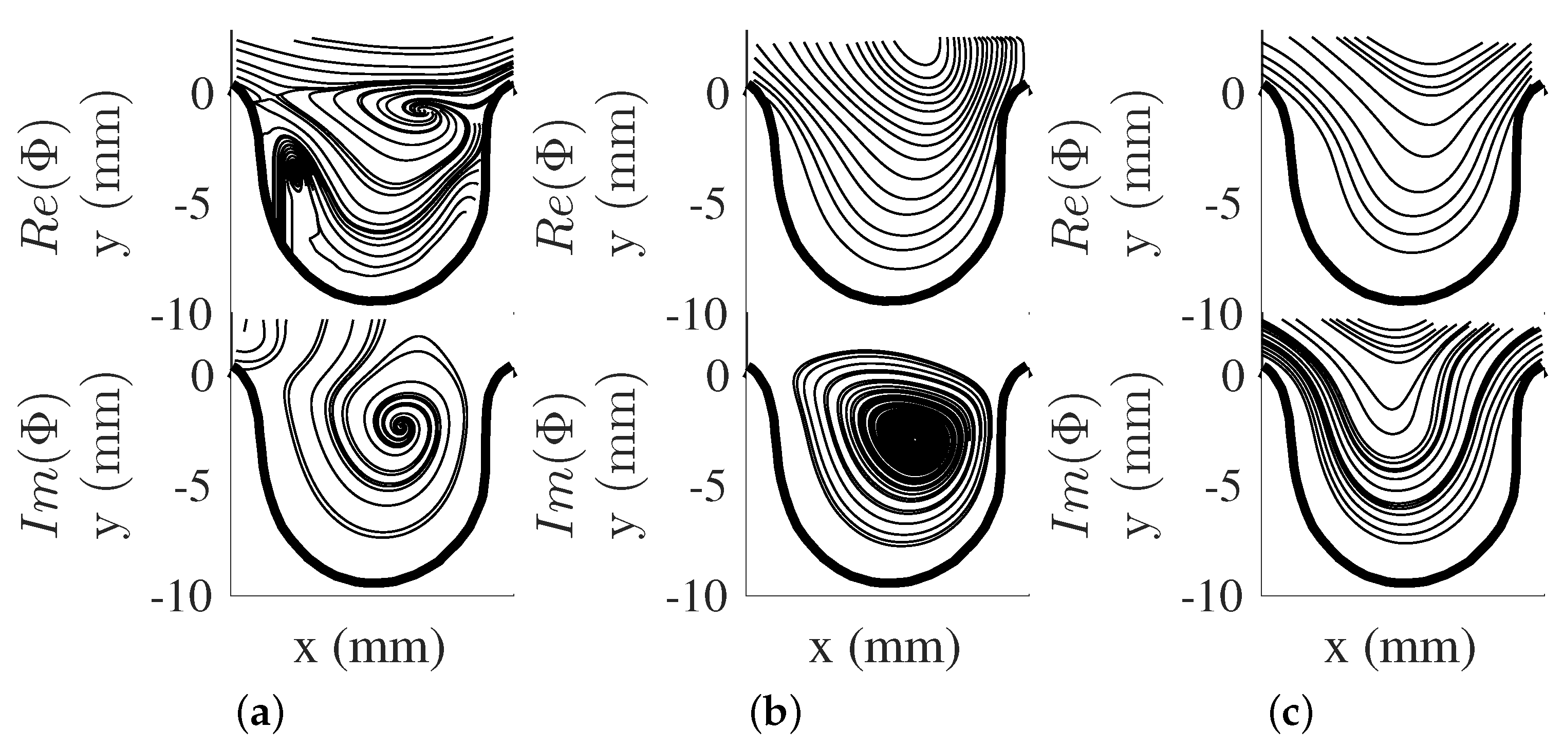
The dynamical behavior of the flow structures can be obtained by using DMD. The DMD modes ( Φ ( x , y ) , see Equation (12)), were obtained and shown as vector representation in Figure 5a–c for R e p = 50 and Figure 6a–c for R e p = 150 . The eigendecomposition of the rectangular matrix A ˜ provided real and imaginary components of DMD modes with each mode pair associated with a single frequency. Furthermore, DMD modes can be seen as the projection of the POD modes Υ to the eigenvector W , which contains other flow structures with different frequencies. In this study, the first few DMD modes are presented here from their spectra and energy contribution. The modes captured are associated with the pump’s driving frequency and its harmonics (i.e., 0.4 Hz, 0.8 Hz, and 1.6 Hz). Further analysis of these DMD mode shape pairs provide the motion of the flow structure by taking the phase shift of the complex DMD mode. This motion showed that a vortical structure forms from the proximal side of the cavity to the aneurysm opening for both R e p = 50 and R e p = 150 . With this in mind, the current study showed that the motion of the vortical structure was captured in one DMD mode shape, while spread out in the POD modes results. It was also noted that the impact of R e p to the DMD modes was minimal for both scenarios, as R e p was varied through input flow velocity, and α was kept constant for both conditions. This will be more evident in the DMD energy analysis.
POD and DMD both provide important insight on the flow field. POD modes showed the presence of different spatial flow structures that contained different fluctuating kinetic energies. DMD, on the other hand, provided information on flow structures at a particular frequency. The behaviors of the large-scale structures were captured differently by each method. In this study, DMD captured the vortical movement in one DMD mode shape and different mode shapes in POD.

5.2. POD and DMD Energies

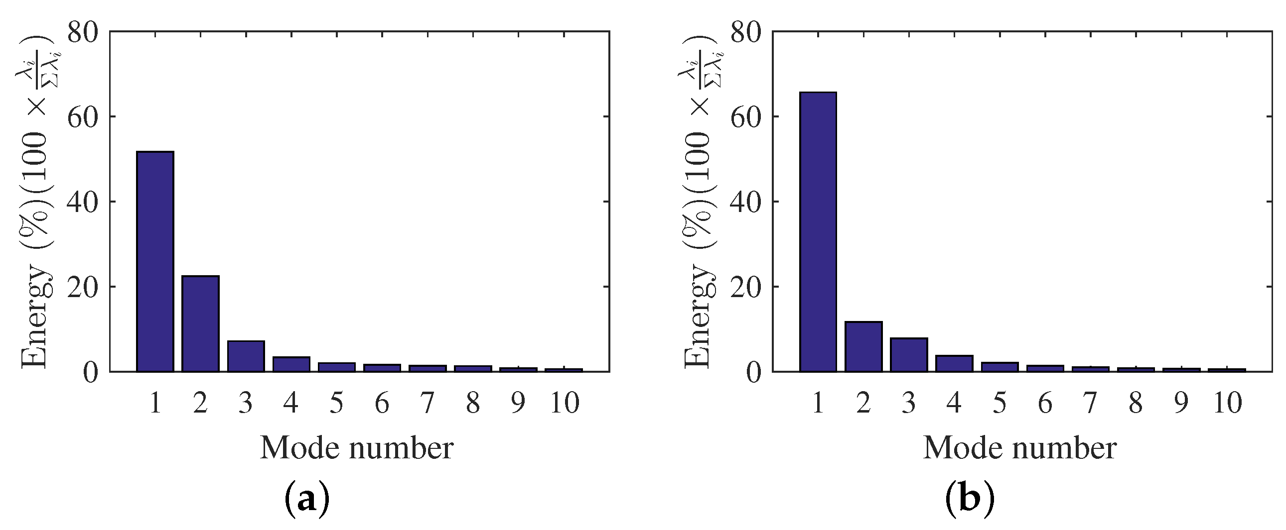
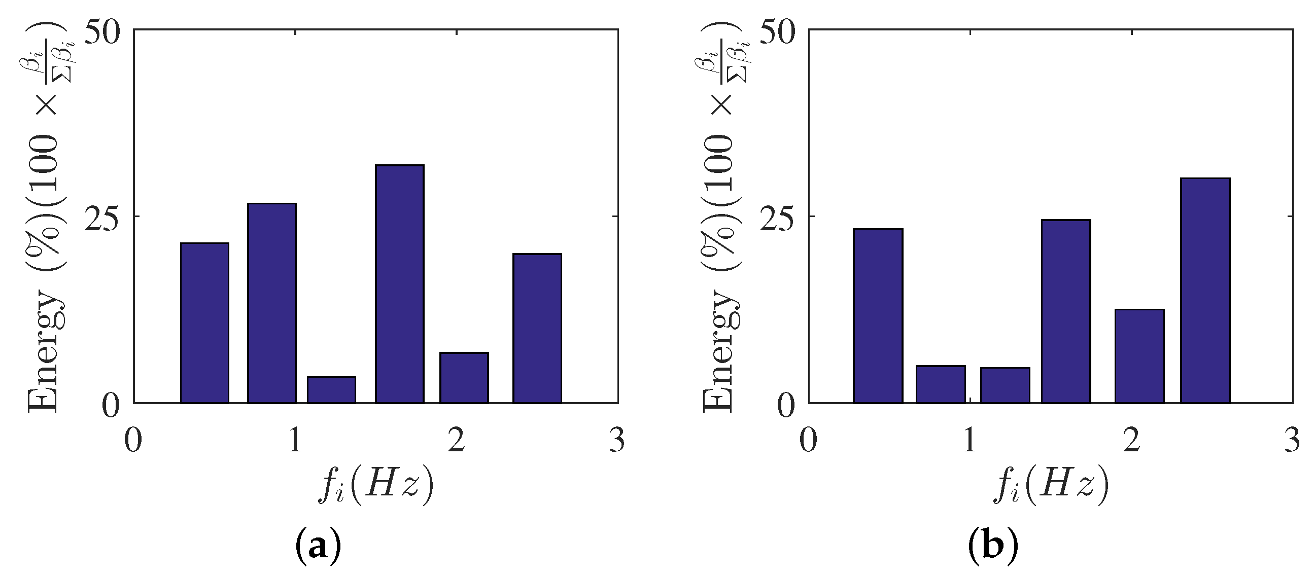
The mode energy contributions are presented here to gain insight on the important role of the mode shapes to the observed flow behavior. Figure 7a,b shows the POD relative contribution (i.e., ratio of the captured energy by each POD mode to the total fluctuating kinetic energy) for the first few modes of each R e p scenario. The POD-mode energy contributions were obtained using Equation (4), while the total fluctuating kinetic energy can be estimated by adding all the eigenvalues ( λ i ). For DMD, the mode contributions ( β ) were obtained from Equation (14) using the optimal vector amplitude approach [60] and are shown in Figure 8a,b for each scenario. Each DMD energy contribution is presented as magnitude of β as a function of frequency ( f i ) , where ( f i ) were determined using Equation (11). The mean flow contribution was removed in DMD results to focus on the fluctuating components of the velocity field. Furthermore, the DMD mode contributions are shown as relative contributions for ease of comparison with POD results.
The POD energy results for the R e p = 50 condition (Figure 7a) showed that the mode contributions decreased with increasing POD mode numbers. The results also showed how each mode captured a certain percentage of the total fluctuating kinetic energy content of the flow. Furthermore, the results highlighted how POD captured the high energetic features within the first few modes as a result of the optimization problem in Equation (2). The POD modes are the optimal basis functions used to describe fluctuating kinetic energy. For R e p = 50 and R e p = 150 , the first five POD modes were sufficient to describe 90 % of the fluctuating kinetic energy of the flow field. Higher POD mode numbers were not used as they have smaller contributions compared to the first five modes.
The DMD mode contributions can be seen in Figure 8a,b for R e p = 50 and R e p = 150 , respectively. In this study, the captured DMD modes were stable and mode contributions were dependent on the captured frequencies. The optimal amplitude approach showed that the mode contributions to the flow, apart from the mean flow, were coming from the 0.8 Hz and 1.6 Hz, which were the integer multiples of 0.4 Hz. These frequency multiples were captured due to the frequency spacing obtained to be Δ f 0.4 Hz from the DMD analysis. The frequencies were also similar for R e p = 50 and R e p = 150 , which further showed the minimal impact of R e p to the captured DMD modes. However, the figures showed how the contributions of these DMD modes varied with the change in R e p . The contributions of highly dominant DMD modes were appropriately selected for low-order flow reconstruction. Furthermore, the dominant frequencies were evident with the flow reconstruction results which will be discussed in the next few sections.
The POD- and DMD-mode energy results provide important information on contributions of each mode shape. POD energy results show decreasing fluctuating kinetic energy contributions with increasing mode shapes. This can guide the researcher on the number of modes to use to describe the flow in detail. On the other hand, the DMD-mode shape contribution can be appropriately selected to represent the flow field. The optimal vector approach can be used to aid the researcher to select and study the modes that are physically relevant to the flow field.

6. Flow field Reconstruction

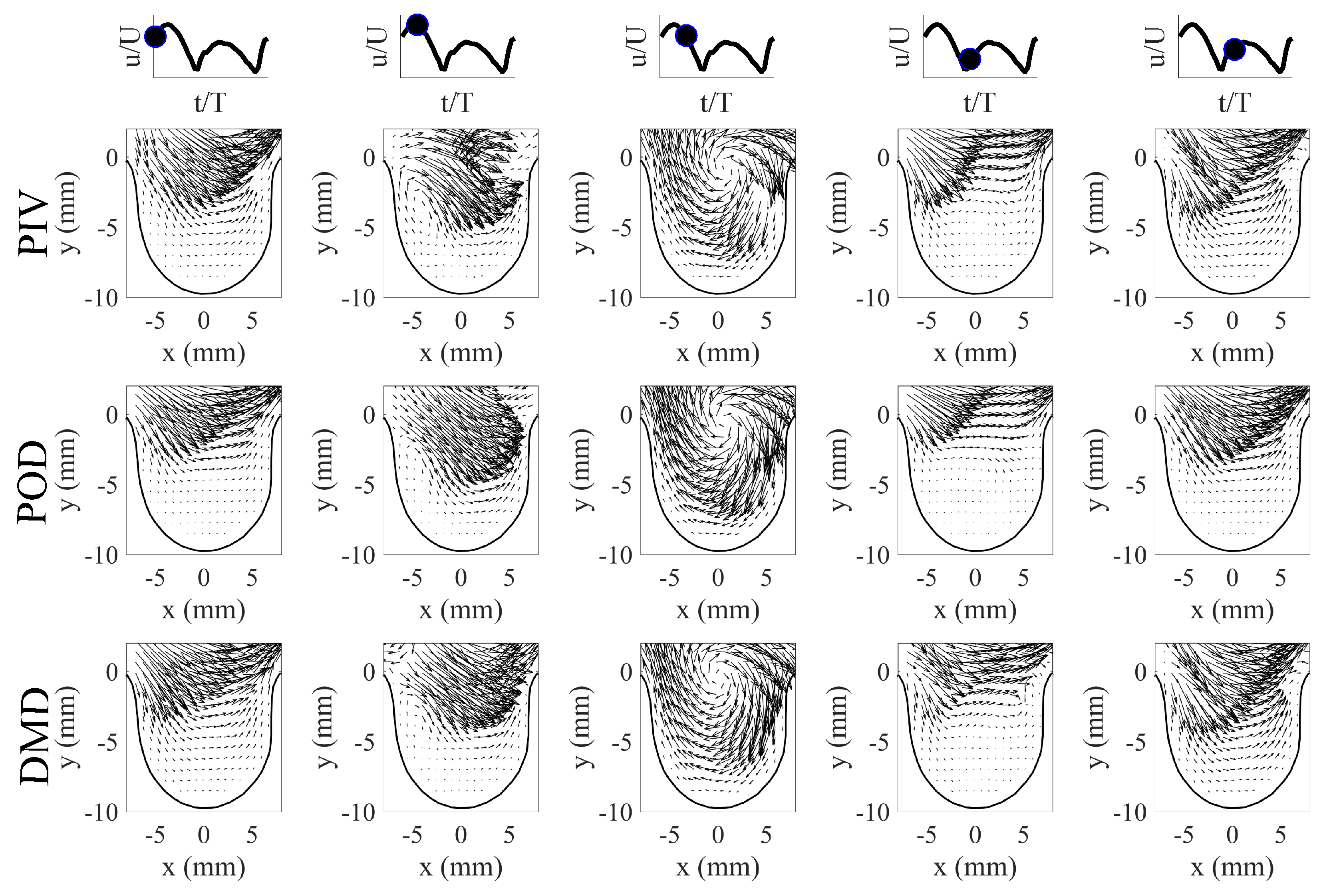
Low-order flow field reconstructions using POD and DMD were performed to mathematically model the flows and their behavior. For POD, the low-order reconstructions of the velocity field at time t (i.e., U ( x , y , t ) ) were performed using Equation (1) using the first five POD modes (i.e., N = 5 ) and their respective time-varying coefficients ( a i ( t ) ). In order to use Equation (1), the time-varying coefficients were first determined by projecting each PIV image to the POD modes (i.e., using Equation (5)). This projection step allowed us to determine the contribution of each POD mode to the velocity field at time instance t. The time-information of the coefficients was obtained through the PIV system trigger and pump piston position from the experiment. This was then used to arrange the coefficients to fit a single cycle flow evolution. Furthermore, a spline curve-fit was performed for each a i ( t ) to determine a mathematical relationship of their behavior. The curve fit operation along with the POD modes allowed for flow field reconstruction at any given time instance using POD. For DMD flow field reconstructions, Equation (13) was used for DMD using an appropriate amount of modes based on their contribution. In this investigation, 0 Hz, 0.4 Hz, 0.8 Hz, 1.6 Hz, and 2.4 Hz were used for R e p = 50 flow reconstruction. Note that the flow fields can be reconstructed at any given time instance t using Equation (13). The results of the flow reconstructions using POD and DMD for R e p = 50 are shown in Figure 9 for select time phases in the flow cycle. For brevity, only the first half of the flow cycle is shown here, as the second half showed similar vortical structure trends in aneurysm geometry. A similar flow trend with a slight change in vortex core location was observed for the R e p = 150 scenario, and thus not shown here.
The results in Figure 9 show that flow behavior contained different flow features at different phases of the flow cycle. The flow evolution from the PIV images contained an attached flow in the aneurysm phase, a vortex formation phase, vortex evolution and movement phase, and a vortex decay phase. The observed flow behavior in the aneurysm (i.e., vortex moved from the proximal to the aneurysm opening) was a response to the state of the incoming flow from the pipe. In this study, the vortex exited the aneurysm opening from the aneurysm’s proximal side as the flow in the pipe reached near zero velocity, and this was also observed by Yu et al. [29] for their sidewall aneurysm studies. With this flow trend in mind, both POD and DMD methods produced comparable velocity field reconstructions when compared to the PIV results. The mathematical models from POD and DMD captured key flow features, and each method provided energy and dynamic perspectives on the flow evolution. The flow reconstruction from POD, along with the mean flow, showed velocity field reconstructions that were described by highly energetic modes ( Ψ i ) and their time-varying coefficients ( a i ( t ) ). The motion of the vortical structure and other flow features were optimally captured within the first few POD modes (see Section 5.1). The flow reconstruction from DMD on the other hand, showed the velocity fields that contained dynamical information of the flow structures. The flow field evolution can be described by the combination of appropriately selected DMD modes Φ i , with each mode identified by a specific frequency information and growth/decay behavior. The mathematical flow model using DMD can thus capture the flow behavior, which was the vortex motion in the aneurysm.
The low-order reconstruction results using POD or DMD can provide accurate representation of the flow field. With appropriately selected modes, the mathematical models provided by each method can represent the flow field at any given time instance. This can aid the researcher in looking at the flow evolution in great detail, which would have been challenging with phase-locked measurements. Thus, depending on the needs of the research, POD and DMD can provide physical insight to the flow field at hand.

7. Conclusions

POD and DMD were used to quantify the flow behavior in an aneurysm flow. For this study, 2D Particle Image Velocimetry (2D PIV) experiments were conducted on the mid-plane for an idealized, rigid, saccular aneurysm model. Velocimetry measurements were performed at inflow scenario of peak Reynolds numbers R e p = 50 and R e p = 150 and Womersley number α = 2 . Inflow scenario was precisely controlled using a piston pump system. The pump system was synchronized with the PIV system to determine the flow field in relation to the flow cycle, as well as for use with the POD coefficients. POD and DMD were performed on the PIV images to extract the energetic and dynamic modes, energies, and POD time-varying coefficients to study the behavior of the flow field. Low-order velocity flow field representations were also performed on the flow scenario to capture the vortical structure behavior in the aneurysm.
POD provided insight on the velocity data by capturing the important and unique flow features in the flow field. The POD modes showed different and spatial structures present in the flow for both R e p = 50 and R e p = 150 . Furthermore, the vortical structure formation and movement were captured by the first few POD modes for both scenarios. The POD energies quantified the fluctuating kinetic energy content for each POD mode, used to determine the number of modes to use for flow field reconstruction. In this study, the first five POD modes were sufficient enough to capture more than 90% of the total fluctuating kinetic energy for R e p = 50 and R e p = 150 . These numbers of POD modes, along with their time-varying coefficients, were used to create a mathematical model of the flow field, which elucidated the interaction of the POD modes to describe the flow field at a given time instance.
DMD provided information on the dynamics of the flow field. The DMD results showed different dynamic modes which were characterized by specific frequency and growth/decay rate. In the current study, the complex DMD modes captured the motion of the vortical structure which moved from the proximal side to the entrance of the aneurysm. The DMD spectrum results were able to capture the stable frequencies of the driving pressure signal of 0.4 Hz and its harmonics for the current inflow condition. However, the spectrum was not impacted by the change in R e p . The impact of R e p was highlighted through the DMD energy results, which provided information on the contribution of the DMD modes, important to describe the flow field. Similar to the POD approach, this information was used to mathematically represent the flow field using the captured DMD modes, frequency and growth rates, and energies.
Both POD and DMD are capable analysis tools to investigate the spatial and temporal behavior of large-scale structures of a given flow field. POD and DMD can be used to create mathematical models to look into the flow evolution in sufficiently high detail and at any time step. This can be more advantageous compared to phase-locked measurements, which can be time-consuming, expensive, and require extensive hardware synchronization. Furthermore, POD and DMD can be used to extract information with a few PIV images. These methods, along with their mathematical models, can be used for validation of numerical or computational data.

Author Contributions

V.D. provided project conceptualization. P.Y. and V.D. have provided equal contribution to the project investigation, data analysis, writing, and editing the manuscript. All authors have read, agreed, and contributed equally to the current version of the manuscript. All authors have read and agreed to the published version of the manuscript.

Funding

This research received no external funding.

Institutional Review Board Statement

Not applicable.

Informed Consent Statement

Not applicable.

Data Availability Statement

Data are available upon request from the corresponding author.

Conflicts of Interest

The authors declare no conflict of interest.

Nomenclature

The following abbreviations, symbols and markings are used in this manuscript:
ALinear coefficient operator matrix
A ˜ Approximated linear coefficient operator matrix to A
C F D Computational Fluid Dynamics
D p Pipe diameter (m)
DData set containing snapshot s 1 to s m 1
D Data set containing snapshot s 2 to s m
DMDDynamic Mode Decomposition
mNumber of snapshots
P I V Particle Image Velocimetry
P O D Proper Orthogonal Decomposition
s i ith velocity field snapshot
R e p Peak Reynolds number
tTime (s)
TTime period (s)
uVelocity component in x-direction (m/s)
Υ Right singular vector from SVD
vVelocity component in y-direction (m/s)
V Left singular vector from SVD
V m a x Maximum centerline velocity in the pipe (m/s)
W Eigenvectors of A ˜
x , y Cartesian coordinates
α Womersley number
β DMD amplitudes
β k kth DMD amplitude
Δ t Time step (s)
Λ Eigenvalues of A ˜
λ i ith eigenvalue of A ˜
g i DMD decay rate from ith real component of Λ
f i DMD frequency from ith imaginary component of Λ
ν b Blood kinematic viscosity (m 2 /s)
ν f Kinematic viscosity (m 2 /s)
Φ DMD modes
ϕ i ith DMD mode
ρ b Blood density (kg/m 3 )
ρ f Fluid density (kg/m 3 )
Σ Rectangular diagonal matrix from SVD
ω Angular frequency (rad/s)
V a n d Vandermonde matrix
Ψ i ith POD mode
ψ u u i Streamwise component of ith POD mode
ψ v v i Transverse component of ith POD mode
Ω x y Domain of interest
Tensor product
Ensemble averaging

References

  1. Byrne, G.; Mut, F.; Cebral, J. Quantifying the large-scale hemodynamics of intracranial aneurysms. Am. J. Neuroradiol. 2014, 35, 333–338. [Google Scholar] [CrossRef] [PubMed] [Green Version]
  2. Daroczy, L.; Abdelsamie, A.; Janiga, G.; Thevenin, D. State Detection and Hybrid Simulation of Biomedical Flows. In Proceedings of the Tenth International Symposium on Turbulence and Shear Flow Phenomena, Chicago, IL, USA, 7–9 July 2017; Begel House Inc.: Danbury, CT, USA, 2017. [Google Scholar]
  3. Janiga, G. Quantitative assessment of 4D hemodynamics in cerebral aneurysms using proper orthogonal decomposition. J. Biomech. 2019, 82, 80–86. [Google Scholar] [CrossRef] [PubMed]
  4. Yu, P.; Durgesh, V.; Xing, T.; Budwig, R. Application of Proper Orthogonal Decomposition to Study Coherent Flow Structures in a Saccular Aneurysm. J. Biomech. Eng. 2021, 143, 061008. [Google Scholar] [CrossRef] [PubMed]
  5. Habibi, M.; Dawson, S.; Arzani, A. Data-driven pulsatile blood flow physics with dynamic mode decomposition. Fluids 2020, 5, 111. [Google Scholar] [CrossRef]
  6. Le, T.B. Dynamic modes of inflow jet in brain aneurysms. J. Biomech. 2021, 116, 110238. [Google Scholar] [CrossRef]
  7. Arzani, A.; Dawson, S.T. Data-driven cardiovascular flow modelling: Examples and opportunities. J. R. Soc. Interface 2021, 18, 20200802. [Google Scholar] [CrossRef]
  8. Yu, P.; Durgesh, V. Application of Dynamic Mode Decomposition to Study Temporal Flow Behavior in a Saccular Aneurysm. J. Biomech. Eng. 2022, 144. [Google Scholar] [CrossRef]
  9. Munson, B.R.; Okiishi, T.H.; Huebsch, W.W.; Rothmayer, A.P. Fluid Mechanics; Wiley: Singapore, 2013. [Google Scholar]
  10. Shankar, P.; Deshpande, M. Fluid mechanics in the driven cavity. Annu. Rev. Fluid Mech. 2000, 32, 93–136. [Google Scholar] [CrossRef] [Green Version]
  11. Ku, D.N. Blood flow in arteries. Annu. Rev. Fluid Mech. 1997, 29, 399–434. [Google Scholar] [CrossRef]
  12. Lasheras, J.C. The biomechanics of arterial aneurysms. Annu. Rev. Fluid Mech. 2007, 39, 293–319. [Google Scholar] [CrossRef] [Green Version]
  13. Sakalihasan, N.; Limet, R.; Defawe, O.D. Abdominal aortic aneurysm. Lancet 2005, 365, 1577–1589. [Google Scholar] [CrossRef]
  14. Pressler, V.; McNamara, J.J. Thoracic aortic aneurysm Natural history and treatment. J. Thorac. Cardiovasc. Surg. 1980, 79, 489–498. [Google Scholar] [CrossRef]
  15. Brisman, J.L.; Song, J.K.; Newell, D.W. Cerebral aneurysms. N. Engl. J. Med. 2006, 355, 928–939. [Google Scholar] [CrossRef] [Green Version]
  16. WJ, G.; SP, B. Intra-aneurysmal hemodynamics: Turbulence. Trans. Am. Neurol. Assoc. 1954, 13, 163–165. [Google Scholar]
  17. Jain, K. Mechanism of rupture of intracranial saccular aneurysms. Surgery 1963, 54, 347–350. [Google Scholar]
  18. Kallmes, D.F.; Altes, T.; Vincent, D.; Cloft, H.; Do, H.; Jensen, M. Experimental side-wall aneurysms: A natural history study. Neuroradiology 1999, 41, 338–341. [Google Scholar] [CrossRef]
  19. McCormick, W.F.; Acosta-Rua, G.J. The size of intracranial saccular aneurysms: An autopsy study. J. Neurosurg. 1970, 33, 422–427. [Google Scholar] [CrossRef]
  20. International Study of Unruptured Intracranial Aneurysms Investigators. Unruptured intracranial aneurysms—Risk of rupture and risks of surgical intervention. N. Engl. J. Med. 1998, 339, 1725–1733. [Google Scholar]
  21. Ujiie, H.; Tachi, H.; Hiramatsu, O.; Hazel, A.L.; Matsumoto, T.; Ogasawara, Y.; Nakajima, H.; Hori, T.; Takakura, K.; Kajiya, F. Effects of size and shape (aspect ratio) on the hemodynamics of saccular aneurysms: A possible index for surgical treatment of intracranial aneurysms. Neurosurgery 1999, 45, 119–130. [Google Scholar]
  22. Ma, B.; Harbaugh, R.E.; Raghavan, M.L. Three-dimensional geometrical characterization of cerebral aneurysms. Ann. Biomed. Eng. 2004, 32, 264–273. [Google Scholar] [CrossRef]
  23. Raghavan, M.L.; Ma, B.; Harbaugh, R.E. Quantified aneurysm shape and rupture risk. J. Neurosurg. 2005, 102, 355–362. [Google Scholar] [CrossRef] [PubMed]
  24. Burleson, A.C.; Strother, C.M.; Turitto, V.T. Computer modeling of intracranial saccular and lateral aneurysms for the study of their hemodynamics. Neurosurgery 1995, 37, 774–784. [Google Scholar] [CrossRef] [PubMed]
  25. Bluestein, D.; Niu, L.; Schoephoerster, R.; Dewanjee, M. Steady flow in an aneurysm model: Correlation between fluid dynamics and blood platelet deposition. J. Biomech. Eng. 1996, 118, 280–286. [Google Scholar] [CrossRef] [PubMed]
  26. Asgharzadeh, H.; Borazjani, I. Effects of Reynolds and Womersley numbers on the hemodynamics of intracranial aneurysms. Comput. Math. Methods Med. 2016, 2016, 7412926. [Google Scholar] [CrossRef] [PubMed] [Green Version]
  27. Ferguson, G.G. Physical factors in the initiation, growth, and rupture of human intracranial saccular aneurysms. J. Neurosurg. 1972, 37, 666–677. [Google Scholar] [CrossRef] [PubMed]
  28. Egelhoff, C.; Budwig, R.; Elger, D.; Khraishi, T.; Johansen, K. Model studies of the flow in abdominal aortic aneurysms during resting and exercise conditions. J. Biomech. 1999, 32, 1319–1329. [Google Scholar] [CrossRef]
  29. Yu, S.; Zhao, J. A particle image velocimetry study on the pulsatile flow characteristics in straight tubes with an asymmetric bulge. Proc. Inst. Mech. Eng. Part C: J. Mech. Eng. Sci. 2000, 214, 655–671. [Google Scholar] [CrossRef]
  30. Bouillot, P.; Brina, O.; Ouared, R.; Lovblad, K.; Pereira, V.M.; Farhat, M. Multi-time-lag PIV analysis of steady and pulsatile flows in a sidewall aneurysm. Exp. Fluids 2014, 55, 1–11. [Google Scholar] [CrossRef] [Green Version]
  31. Budwig, R.; Elger, D.; Hooper, H.; Slippy, J. Steady flow in abdominal aortic aneurysm models. J. Biomech. Eng. 1993, 115, 418–423. [Google Scholar] [CrossRef]
  32. Fukushima, T.; Matsuzawa, T.; Homma, T. Visualization and finite element analysis of pulsatile flow in models of the abdominal aortic aneurysm. Biorheology 1989, 26, 109–130. [Google Scholar] [CrossRef]
  33. Yu, S.; Zhao, J. A steady flow analysis on the stented and non-stented sidewall aneurysm models. Med. Eng. Phys. 1999, 21, 133–141. [Google Scholar] [CrossRef]
  34. Le, T.B.; Borazjani, I.; Sotiropoulos, F. Pulsatile flow effects on the hemodynamics of intracranial aneurysms. J. Biomech. Eng. 2010, 132, 111009. [Google Scholar] [CrossRef] [PubMed]
  35. Taira, K.; Brunton, S.L.; Dawson, S.T.; Rowley, C.W.; Colonius, T.; McKeon, B.J.; Schmidt, O.T.; Gordeyev, S.; Theofilis, V.; Ukeiley, L.S. Modal analysis of fluid flows: An overview. AIAA J. 2017, 55, 4013–4041. [Google Scholar] [CrossRef] [Green Version]
  36. Lumley, J.L. The structure of inhomogeneous turbulent flows. In Atmospheric Turbulence and Radio Wave Propagation; Yaglom, A.M., Tartarsky, V.I., Eds.; Nauka: Tokyo, Japan, 1967; pp. 166–177. [Google Scholar]
  37. Berkooz, G.; Holmes, P.; Lumley, J.L. The proper orthogonal decomposition in the analysis of turbulent flows. Annu. Rev. Fluid Mech. 1993, 25, 539–575. [Google Scholar] [CrossRef]
  38. Holmes, P.; Lumley, J.L.; Berkooz, G.; Rowley, C.W. Turbulence, Coherent Structures, Dynamical Systems and Symmetry; Cambridge University Press: Cambridge, MA, USA, 2012. [Google Scholar]
  39. Rowley, C.W.; Mezi, I.; Bagheri, S.; Schlatter, P.; Henningson, D. Spectral analysis of nonlinear flows. J. Fluid Mech. 2009, 641, 115–127. [Google Scholar] [CrossRef] [Green Version]
  40. Schmid, P.J. Dynamic mode decomposition of numerical and experimental data. J. Fluid Mech. 2010, 656, 5–28. [Google Scholar] [CrossRef] [Green Version]
  41. Taira, K.; Hemati, M.S.; Brunton, S.L.; Sun, Y.; Duraisamy, K.; Bagheri, S.; Dawson, S.T.; Yeh, C.A. Modal analysis of fluid flows: Applications and outlook. AIAA J. 2020, 58, 998–1022. [Google Scholar] [CrossRef]
  42. Rowley, C.W.; Dawson, S.T. Model reduction for flow analysis and control. Annu. Rev. Fluid Mech. 2017, 49, 387–417. [Google Scholar] [CrossRef] [Green Version]
  43. Yu, P.; Durgesh, V. Comparison of Flow Behavior in Saccular Aneurysm Models Using Proper Orthogonal Decomposition. Fluids 2022, 7, 123. [Google Scholar] [CrossRef]
  44. Cheng, N.S. Formula for the viscosity of a glycerol- water mixture. Ind. Eng. Chem. Res. 2008, 47, 3285–3288. [Google Scholar] [CrossRef]
  45. Volk, A.; Kähler, C.J. Density model for aqueous glycerol solutions. Exp. Fluids 2018, 59, 1–4. [Google Scholar] [CrossRef] [Green Version]
  46. Steiger, H.; Poll, A.; Liepsch, D.; Reulen, H.J. Haemodynamic stress in lateral saccular aneurysms. Acta Neurochir. 1987, 86, 98–105. [Google Scholar] [CrossRef] [PubMed]
  47. Gobin, Y.; Counord, J.; Flaud, P.; Duffaux, J. In vitro study of haemodynamics in a giant saccular aneurysm model: Influence of flow dynamics in the parent vessel and effects of coil embolisation. Neuroradiology 1994, 36, 530–536. [Google Scholar] [CrossRef] [PubMed]
  48. Ugron, Á.; Farinas, M.I.; Kiss, L.; Paál, G. Unsteady velocity measurements in a realistic intracranial aneurysm model. Exp. Fluids 2012, 52, 37–52. [Google Scholar] [CrossRef]
  49. Womersley, J.R. Method for the calculation of velocity, rate of flow and viscous drag in arteries when the pressure gradient is known. J. Physiol. 1955, 127, 553–563. [Google Scholar] [CrossRef]
  50. Steiger, H.J.; Poll, A.; Liepsch, D.; Reulen, H.J. Basic flow structure in saccular aneurysms: A flow visualization study. Heart Vessel. 1987, 3, 55–65. [Google Scholar] [CrossRef]
  51. Liou, T.M.; Liou, S.N. A review on in vitro studies of hemodynamic characteristics in terminal and lateral aneurysm models. Proc. Natl. Sci. Counc. Repub. China. Part B Life Sci. 1999, 23, 133. [Google Scholar]
  52. White, F.M.; Corfield, I. Viscous Fluid Flow; McGraw-Hill: New York, NY, USA, 2006; Volume 3. [Google Scholar]
  53. Sirovich, L. Turbulence and the dynamics of coherent structures. I. Coherent structures. Q. Appl. Math. 1987, 45, 561–571. [Google Scholar] [CrossRef] [Green Version]
  54. Durgesh, V.; Naughton, J. Multi-time-delay LSE-POD complementary approach applied to unsteady high-Reynolds-number near wake flow. Exp. Fluids 2010, 49, 571–583. [Google Scholar] [CrossRef]
  55. Durgesh, V.; Naughton, J.W.; Whitmore, S.A. Experimental investigation of base-drag reduction via boundary-layer modification. AIAA J. 2013, 51, 416–425. [Google Scholar] [CrossRef]
  56. Tu, J.H.; Rowley, C.W.; Luchtenburg, D.M.; Brunton, S.L.; Kutz, J.N. On dynamic mode decomposition: Theory and applications. arXiv 2013, arXiv:1312.0041. [Google Scholar]
  57. Kutz, J.N.; Brunton, S.L.; Brunton, B.W.; Proctor, J.L. Dynamic Mode Decomposition: Data-Driven Modeling of Complex Systems; SIAM: Philadelphia, PA, USA, 2016. [Google Scholar]
  58. Chen, K.K.; Tu, J.H.; Rowley, C.W. Variants of dynamic mode decomposition: Boundary condition, Koopman, and Fourier analyses. J. Nonlinear Sci. 2012, 22, 887–915. [Google Scholar] [CrossRef]
  59. Wynn, A.; Pearson, D.; Ganapathisubramani, B.; Goulart, P.J. Optimal mode decomposition for unsteady flows. J. Fluid Mech. 2013, 733, 473–503. [Google Scholar] [CrossRef] [Green Version]
  60. Jovanović, M.R.; Schmid, P.J.; Nichols, J.W. Sparsity-promoting dynamic mode decomposition. Phys. Fluids 2014, 26, 024103. [Google Scholar] [CrossRef]
  61. Proctor, J.L.; Brunton, S.L.; Kutz, J.N. Dynamic mode decomposition with control. SIAM J. Appl. Dyn. Syst. 2016, 15, 142–161. [Google Scholar] [CrossRef] [Green Version]
Figure 1. Schematic of the idealized, saccular, aneurysm model.
Fluids 07 00165 g001
Figure 2. Two-dimensional PIV system setup for the aneurysm flow investigation.
Fluids 07 00165 g002
Figure 3. POD modes for R e p = 50 . (a) Ψ 1 , (b) Ψ 2 , (c) Ψ 3 , (d) Ψ 4 , and (e) Ψ 5 .
Fluids 07 00165 g003
Figure 4. POD modes for R e p = 150 . (a) Ψ 1 , (b) Ψ 2 , (c) Ψ 3 , (d) Ψ 4 , and (e) Ψ 5 .
Fluids 07 00165 g004
Figure 5. DMD modes for R e p = 50 . (a) 0.4 Hz mode, (b) 0.8 Hz mode, (c) 1.6 Hz mode.
Fluids 07 00165 g005
Figure 6. DMD modes for R e p = 150 . (a) 0.4 Hz mode, (b) 0.8 Hz mode, (c) 1.6 Hz mode.
Fluids 07 00165 g006
Figure 7. POD-mode energies. (a) R e p = 50 , (b) R e p = 150 .
Fluids 07 00165 g007
Figure 8. DMD-mode energies. (a) R e p = 50 , (b) R e p = 150 .
Fluids 07 00165 g008
Figure 9. POD and DMD low-order reconstruction for the first half of the flow cycle for R e p = 50 . First row: PIV results, Second row: POD results, Third row: DMD results.
Fluids 07 00165 g009
Publisher’s Note: MDPI stays neutral with regard to jurisdictional claims in published maps and institutional affiliations.