Article

Physical Model of a Single Bubble Growth during Nucleate Pool Boiling

Independent Researcher, 4202 Naklo, Slovenia
Fluids 2022, 7(3), 90; https://doi.org/10.3390/fluids7030090
Submission received: 4 February 2022 / Revised: 24 February 2022 / Accepted: 25 February 2022 / Published: 27 February 2022
(This article belongs to the Section Heat and Mass Transfer)

Abstract

:
A simplified physical model of a single bubble growth during nucleate pool boiling was developed. The model was able to correlate the experimentally observed data of the bubble’s growth time and its radius evolution with the use of the appropriate input parameters. The calculated values of separated heat fluxes from the heater wall, thermal boundary layer, and to the bulk liquid gave us a new insight into the complex mechanisms of the nucleate pool boiling process. The thermal boundary layer was found to supply the majority of the heat to the growing bubble. The heat flux from the thermal boundary layer to the bubble was found to be close to the Zuber’s critical heat flux limit (890 kW/m2). This heat flux was substantially larger than the input heater wall heat flux of 50 kW/m2. The thermal boundary layer acts as a reservoir of energy to be released to the growing bubble, which is filled during the waiting time of the bubble growth cycle. Therefore, the thickness of the thermal boundary layer was found to have a major effect on the bubble’s growth time.

Graphical Abstract

1. Introduction

Nucleate boiling is one of the most efficient heat transfer mechanisms. The reason for that is the phase change—evaporation of the working fluid, which causes the bulk liquid to maintain its temperature at or below the saturation temperature corresponding to the system pressure. Nucleate pool boiling is used in many engineering and industrial applications, such as electronics cooling [1], nuclear power [2], and many others. Therefore, enhancing boiling heat transfer would result in improved efficiency of many key aspects of our modern society. Better understanding of the fundamental characteristics of nucleate pool boiling is one of the essential conditions, which has to be met in order to make further improvements in efficiency of the boiling process.
During nucleate pool boiling, the bubbles nucleate at the heater surface and then they grow until they depart due to the buoyancy force. The hemispherical vapor bubble’s radius (r) grows with time (t) following Equation (1).
r = r 0 + C r   t 1 / 2
This type of equation was proposed by Van Stralen [3] and Cooper and Lloyd [4]. The bubble radius seems to follow the bubble growth equation (Equation (1)) as observed with experimental data by Thorncroft et al. [5], Yoon et al. [6], Gerardi et al. [7], and Mahmoud and Karayiannis [8]. It is worth pointing out that the growth rate of a bubble is dependent on multiple parameters, e.g., input heat flux and liquid superheat [9].
The cycle of the bubble growth consists of two periods: growth time (tg) and waiting time (tw). Growth time is the period of growth of vapor nucleus after reaching the critical dimension, which ends with detachment of the bubble from the heater surface (Niro and Beretta [10]). After detachment the waiting period starts and lasts until the start of the next cycle. The bubble nucleation frequency (f) is inversely proportional to the sum of the growth and waiting time (Equation (2)).
f = 1 t c = 1 t g + t w
The growth time, when bubble nucleation and growth occur, is typically in order of magnitude of a few milliseconds [7]. The experimentally obtained results from the study of Gerardi et al. [7] show growth times of approximately 10 milliseconds (varying from 7.7 ms to 10.7 ms within three consecutive growth cycles), which represented 12% of the total time of a cycle (tc). We are well aware that these quantities change with the changing of the input heat flux.
Both Kim [11] and Liao et al. [12] stated that a substantial contribution of the heat gained by a growing vapor bubble during nucleate boiling is through the dome of the bubble from the superheated liquid layer also known as the thermal boundary layer. Therefore, the bulk liquid in the superheated boundary layer supplies a sufficient amount of energy to the bubble [12]. Kim [11] concluded that the heat transferred with microlayer evaporation and contact line heat transfer do not account for more than approximately 25% of the overall heat transfer. The thermal boundary layer and its influence were theoretically investigated by Liao et al. [12] with thickness varying from 1 µm up to 100 µm. On the other hand, De and Judd [13] observed the extrapolated superheated liquid layer thickness in the approximate range from 0.2 mm up to 0.6 mm.
Study of pool boiling heat transfer with experimental approach has been the dominant path of research in the recent years. Modified heater surfaces, such as porous surface structures were tested by Zhang et al. [14], Huang et al. [15], Mehdikhani et al. [16], and other types of modified heater surfaces, e.g., Ranjan et al. [17], Nirgude and Sahu [18], Singh and Sharma [19], were subjected to pool boiling experiments and had shown enhanced heat transfer characteristics. On the other hand, there are many different theoretical models of bubble growth [6,20,21] and also a large number of approaches with simulation of pool boiling [22,23,24,25,26] available in the heat transfer literature. Stephan and Hammer [20] developed a model for calculation of heat transfer coefficients and bubble growth rates based on separate calculation of heat conduction thru the micro region near the triple contact line and the macro regions elsewhere. Chien and Webb [21] formulated a semi-analytical model for nucleate boiling inside the subsurface tunnels with surface pores, which uses two empirical constants to predict the heat transfer coefficient, bubble departure diameter, and nucleation frequency. Yoon et al. [6] presented a mesh-free numerical method for direct calculation of bubble growth and departure process without modeling the superheated liquid microlayer beneath the bubble. All of the models described above require input parameters to develop the bubble’s evolution characteristics, e.g., growth time and departure diameter. Our model, on the other hand, uses the bubble’s growth characteristics (growth rate and growth time) from experimental database in order to separate/estimate the contributions of the different regions (e.g., thermal boundary layer) of the working fluid to the total heat transferred to/from the bubble. Most of the models and simulations are fairly complex and they usually do not reveal the underlying fundamental physical principles or evaluate the individual contributions of the energy transferred to/from the growing bubble. In this study, a simplified physical model of a single bubble growth was proposed and validated on a set of typical data collected with experimental observations (Gerardi et al. [7]). The purpose of the model was the determination of the different contributions of the heat supply to the bubble growth.
The paper presents a newly developed simplified physical model of a single bubble growth during nucleate pool boiling. The model involves multiple assumptions and simplifications, e.g., neglecting of the microlayer below the growing bubble, in order to keep the calculations relatively simple with low computational cost and to enable us to draw conclusions, which extend our fundamental knowledge of the nucleate pool boiling process.

2. Physical Model

2.1. Assumptions of the Model

The simplified physical model of the bubble growth is based on a few assumptions. These assumptions are made in order to simplify the problem to an extent, which enables us to analytically calculate the majority of the parameters involved.
The model is based on the following assumptions:
  • The vapor bubble starts to grow from a small initial spherical cap of a vapor attached to the heater surface;
  • The surface of the heater is horizontally oriented, and it is flat—ideally smooth;
  • The size and geometry of the microlayer are neglected;
  • The shape of the bubble is spherical (hemispherical) due to the surface tension of the surrounding liquid;
  • The radius of the bubble changes with time following the bubble growth equation (Equation (1));
  • The heat transferred to the bubble causes evaporation of the adjacent liquid which is responsible for bubble’s growth;
  • The three separated heat fluxes and thickness of the thermal boundary layer do not change with time.
The physical model was iteratively calculated in the numerical computing environment Matlab. The algorithm needs several input parameters, and it is presented in Section 2.2.

2.2. The Calculation Algorithm

The algorithm needs input of two main parameters: initial bubble radius (r0) and initial liquid contact angle (θ0). The bubble is assumed to start at a small size of vapor with a shape of a spherical cap attached to a flat heater surface. The simplified geometry of the bubble is represented in Figure 1. Firstly, the geometrical parameters (e.g., surface area and volume) of the initial bubble are calculated.
The iterative calculation of the parameters of the bubble starts with calculation of the gain of the volume of the bubble due to the heat transferred to it (ΔVi), which is assumed to cause evaporation of the surrounding liquid (Equation (3)).
Δ V i = Δ m i ρ = Δ Q i ρ   h l v = ( q ˙ w   A w , i 1 + q ˙ t b l   A t b l , i 1 + q ˙ s c   A s c , i 1 )   Δ t ρ   h l v
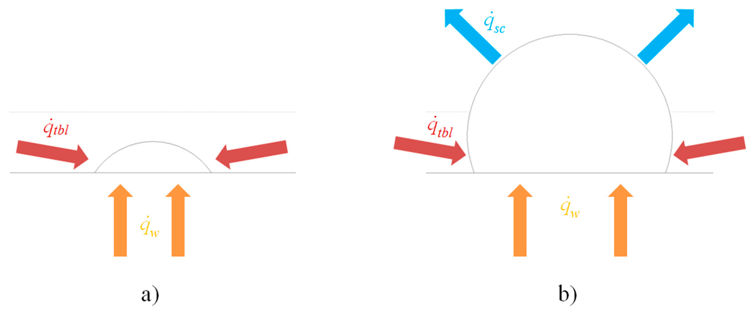
Heat transfer occurs on the solid–vapor and the liquid–vapor interfaces. The heat flux to and from the bubble is divided into three parts: heat flux from the heater wall to the vapor bubble ( q . w ), heat flux from the surrounding superheated liquid in the thermal boundary layer to the bubble ( q . t b l ), and heat flux or heat losses from the spherical cap of the bubble above the thermal boundary layer to the bulk liquid ( q . s c ). The three separated heat transfer regions are depicted in Figure 2. The heat fluxes are assumed to be constant during unchanged input heat flux from the heater.
The instantaneous total volume of the bubble (Vi) is expressed with Equation (4).
V i = V i 1 + Δ V i
After obtaining the instantaneous radius from the bubble growth equation (Equation (1)), the instantaneous volume (Equation (4)), and equation for volume of a spherical cap (Equation (5)), the geometrical angle (αi) cannot be determined analytically. The angle αi was therefore calculated using the Matlab built-in function fminsearch, assisted by the brute-force method at angles larger than 175°. The initial guess for search of the angle, which satisfies the volume of a spherical cap Vi, was equal to the angle of the previous iteration (αi−1).
V i = π 3 r i 3 ( 2 + cos α i ) ( 1 cos α i ) 2
After determination of the value of the angle αi, other parameters can be easily calculated. The center of the bubble radius from top of the heater surface (zc,i) is defined with Equation (6).
z c , i = r i cos α i
The radius of the circle of contact between the bubble and the heater (ai) is determined with Equation (7).
a i = r i   sin α i
The height of the bubble (hi) is calculated using Equation (8).
h i = r i ( 1 cos α i )
The surface area of the bubble in contact with the heater wall (Aw,i) is defined with Equation (9).
A w , i = π (   r i   sin α i ) 2
In case the height of the bubble (hi) is smaller than or equal to the thermal boundary layer thickness (δ), the surface of the bubble in contact with the thermal boundary layer (Atbl,i) and the surface of the bubble in contact with the bulk liquid (Asc,i) are defined with Equations (10) and (11), respectively.
A t b l , i = 2 π r i 2 ( 1 cos α i )
A s c , i = 0
When the bubble grows to a height larger than the thickness of thermal boundary layer, these surfaces are calculated with Equations (12) and (13), respectively.
A t b l , i = 2 π r i δ
A s c , i = 2 π r i [ r i ( 1 cos α i ) δ ]
Many other parameters of the bubble were and can be calculated inside the algorithm. Only the essential parts of the algorithm are presented in this section. The iterative calculation stops at the point of departure of the bubble from the heater surface (or if the final time-step is reached prior to departure).

3. Results and Discussion

The algorithm for modelling of a single bubble’s growth during nucleate pool boiling was tested and used to gain the result typically measured during boiling experiments with pure water [7]. The working fluid of choice was water at atmospheric pressure, with enthalpy of vaporization (hlv) of 2256.4 kJ/kg and vapor density (ρ) of 0.5982 kg/m3 [27]. The iterative calculation iterates with a time-step of 1 microsecond up to a maximal time of 25 milliseconds. The parameter Cr of the bubble growth equation (Equation (1)) was chosen to be equal to 14 mm/s1/2, so that the bubble growth equation follows the bubble radius evolution observed by Gerardi et al. [7] during boiling of water at the heat flux of 50 kW/m2. The initial bubble nucleus was defined to be small enough to be inside the size range of potentially active nucleation cavities proposed by Hsu [28].

3.1. Determination of the Heat Flux from the Thermal Boundary Layer to the Bubble

The calculation started with the selected input parameters: initial bubble radius (r0): 0.01 mm, initial contact angle (θ0): 145°, thermal boundary layer thickness (δ): 0.3 mm, heat flux from the heater wall to the vapor bubble ( q . w ): 50 kW/m2 and heat flux from the spherical cap of the bubble above the thermal boundary layer to the bulk liquid ( q . s c ): −0.2 kW/m2 (the value is negative considering the system of a growing bubble). The heat flux from the thermal boundary layer to the bubble ( q . t b l ) was varied with the goal of obtaining results similar to the measurements of Gerardi et al. [7]—growth time close to 10 milliseconds.
Table 1 shows effect of variation of the heat flux from the thermal boundary layer ( q . t b l ) on the bubble growth time (tg). The growth time closest to the one typically observed during boiling at input heat flux of 50 kW/m2 was achieved when the applied heat flux from the thermal boundary layer was equal to 890 kW/m2. This heat flux ( q . t b l ) is approaching Zuber’s limit for value of critical heat flux [29] and it is 17.8 times higher than the heater wall heat flux ( q . w ) at the same time. If we separate the contributions of the heat supplied to or from the bubble during the entire growth period, we can observe: Qw = 1.018 × 10⁻⁴ J, Qtbl = 1.381 × 10⁻² J, Qsc = −1.747 × 10⁻⁵ J, while the total heat supplied to the bubble during the entire growth period is equal to 1.389 × 10⁻² J. Therefore, the main contributor of the heat supplied to the growing bubble was the superheated thermal boundary layer.
After a bubble detaches from the heater wall, the thermal boundary layer usually collapses and it has to grow again (during the waiting time) to initiate the next nucleation—quenching heat flux by Gerardi et al. [7]. The thermal boundary layer actually acts as the main accumulator of energy from the heater surface before this energy is transferred to the bubbles and, to a certain extent, also to the bulk liquid during nucleate pool boiling. The heat transferred directly from the heater wall to the bubble is therefore not the primary contributor to the bubble growth. This finding is supported by the claim of Dhir that the energy for evaporation is supplied from the superheated liquid layer that surrounds the bubble after its inception [30].
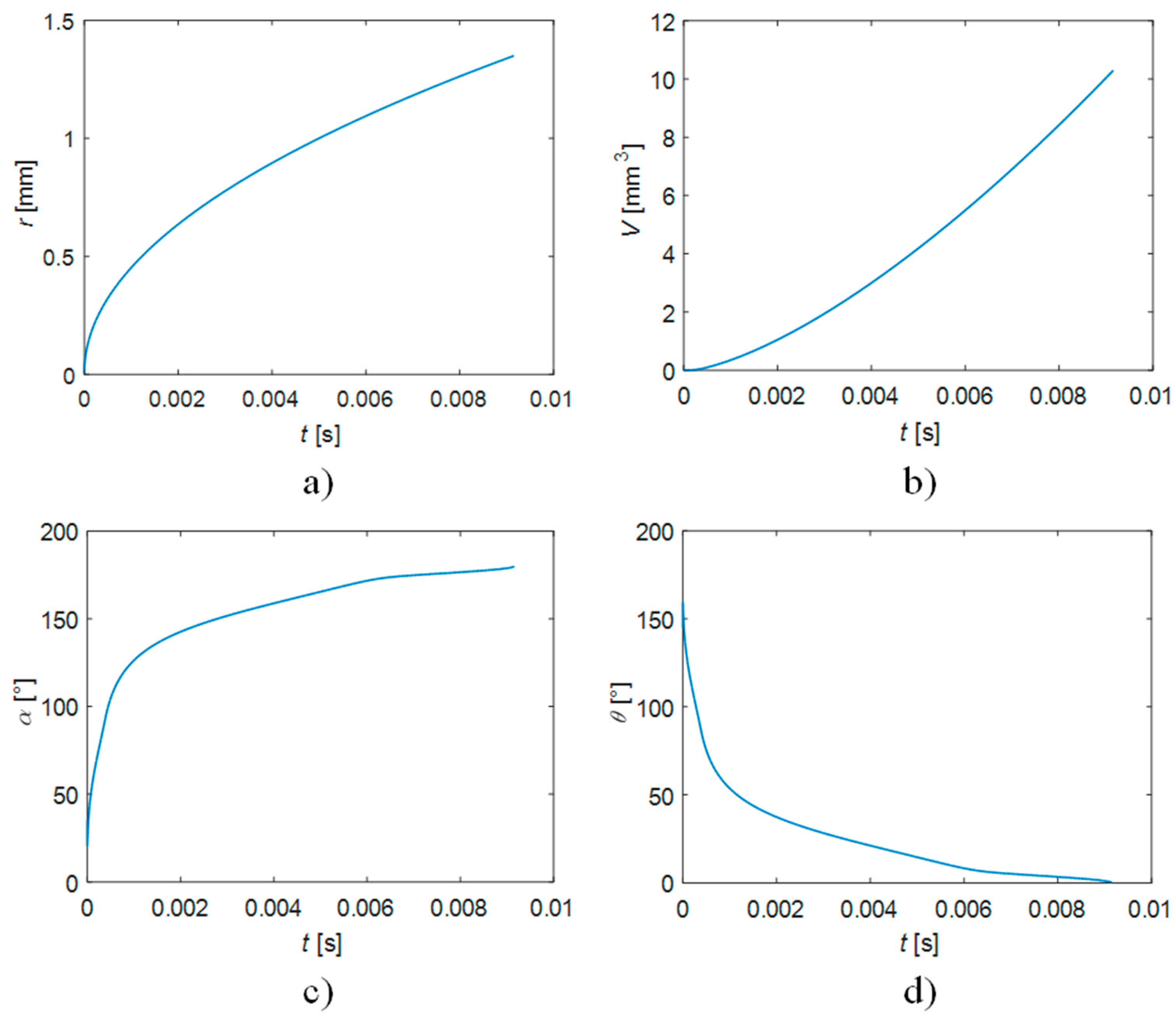
Figure 3 depicts some of the geometrical aspects of the bubble growth. The volume evolution follows a slightly convex shaped curve (increasing slope), which is visible in Figure 3b). On the other hand, Siedel et al. [31] experimentally observed concave shaped behavior (decreasing slope) of time evolution of bubble volume during pool boiling of n-pentane on artificial nucleation sites. These discrepancies could be attributed to the roughness of the heater wall—artificial nucleation sites in the case of experimental observations. The geometrical angle α seems to rapidly drop from its initial value of 35° down to 20.6°, after which it starts to increase up to 180° (Figure 3c). The reason for this initial drop of α is the prescribed evolution of the bubble radius (Figure 3a), which has a steep slope at the beginning. Therefore, in order to satisfy both the evaporative gain in volume of the bubble and prescribed radius (with respect to time), the angle α had to slightly decrease. The evolution of the liquid contact angle (θ) is depicted in Figure 3d.
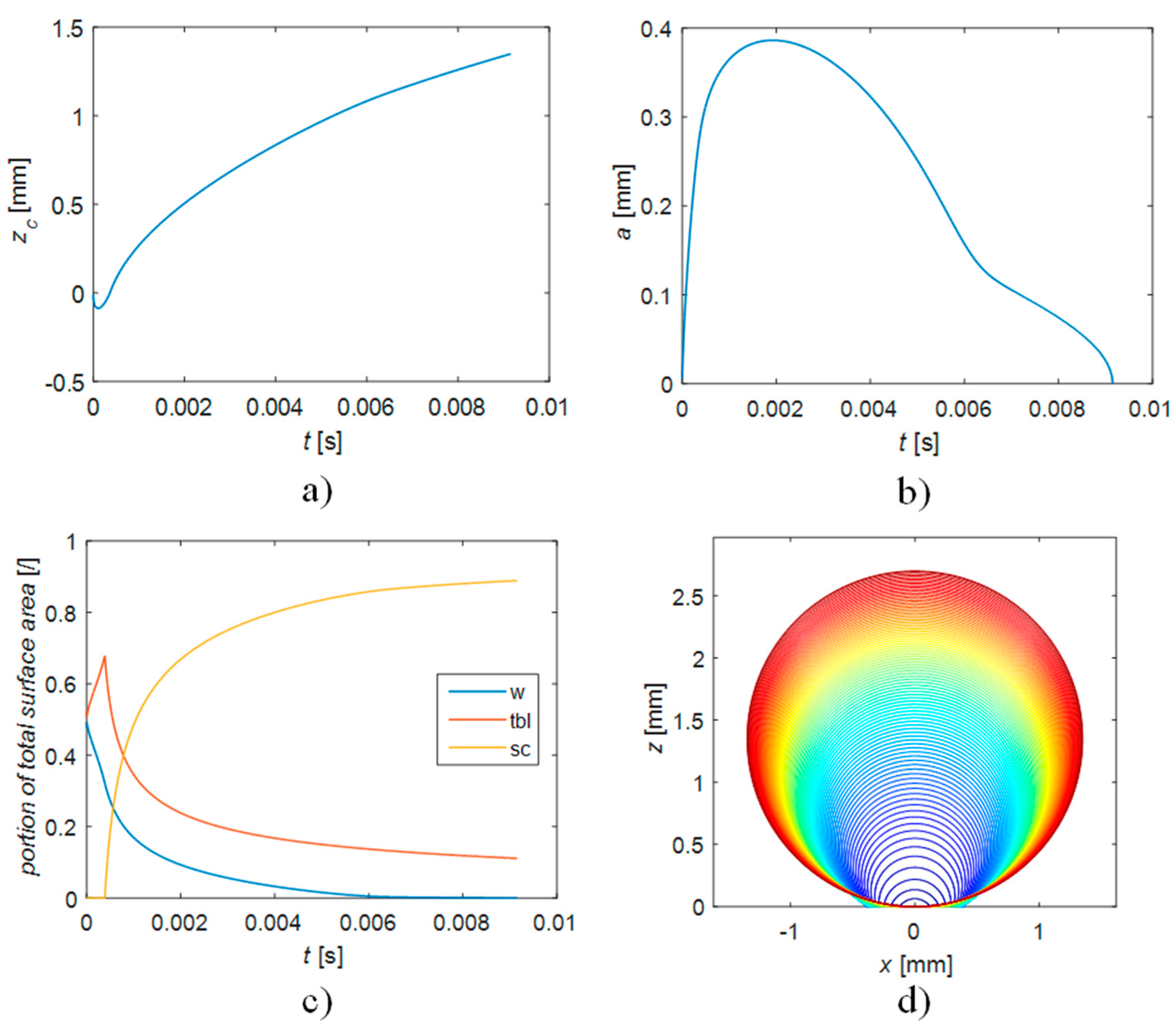
Other viable geometrical parameters of the bubble growth at heat flux from the thermal boundary layer of 890 kW/m2 are presented in Figure 4. The center of the bubble radius (zc) gradually increases from the negative values to the value equal to the bubble departure radius (1.349 mm). The bubble’s base radius (a) increases in the initial part of the bubble growth and then decreases to zero, which is presented in Figure 4b. A similarly shaped curve to the one on Figure 4b was experimentally observed by Kowalewski et al. [32] using high speed video camera and numerical processing of the digital images of bubbles during subcooled pool boiling of water. The portions of the total surface area of the bubble are presented in Figure 4c. The surface areas of the bubble in contact with the hater wall (w) and the thermal boundary layer (tbl) are dominant in the initial phase of the bubble growth, while in the later phases, the portion of the surface area of the spherical cap above the thermal boundary layer (sc) begins to increase and dominate. Evolution of the bubble size is depicted on Figure 4d and is also presented in the attached video (see Supplementary Materials); the individual bubble shapes are drawn with a time-step of 0.1 millisecond.

3.2. Influence of the Heater Wall Heat Flux

Influence of other selected input parameters was also studied, starting with the heater wall heat flux ( q . w ). The calculation started with the input parameters: initial bubble radius (r0): 0.01 mm, initial contact angle (θ0): 145°, thermal boundary layer thickness (δ): 0.3 mm, heat flux from the thermal boundary layer to the bubble ( q . t b l ): 980 kW/m2 and heat flux from the spherical cap of the bubble above the thermal boundary layer to the bulk liquid ( q . s c ): −0.2 kW/m2. The heat flux from the heater wall to the bubble ( q . w ) was varied.
Table 2 summarizes the influence of the heater wall heat flux on the bubble growth. It can be seen that the heat flux from the heater wall does not drastically affect the bubble’s growth period in the range from 25 kW/m2 to 500 kW/m2. The heater wall heat flux has a much smaller effect on the bubble growth than the heat flux from the thermal boundary layer to the bubble. The reason for this could be attributed to the relatively small and constantly decreasing proportion of the total surface (interface) area of the bubble during its growth, which is presented on the Figure 4c.

3.3. Influence of the Heat Flux from the Spherical Cap above the Thermal Boundary Layer

Influence of the heat flux from the bubble to the bulk liquid ( q . s c ) was also studied. The calculation started with the input parameters: initial bubble radius (r0): 0.01 mm, initial contact angle (θ0): 145°, thermal boundary layer thickness (δ): 0.3 mm, heat flux from the heater wall to the vapor bubble ( q . w ): 50 kW/m2 and heat flux from the thermal boundary layer to the bubble ( q . t b l ): 980 kW/m2. The heat flux from the bubble to the bulk liquid ( q . s c ) was varied.
Table 3 shows that the heat losses from the bubble have a considerable effect on the bubble’s growth time, which is still smaller than the one of the heat flux from the thermal boundary layer to the bubble. The heat flux from the bubble to the bulk liquid is dependent on the flow patterns of the bulk liquid in the vicinity of the bubble and the temperature of the bubble’s interface in contact with the bulk liquid.

3.4. Influence of the Thermal Boundary Layer Thickness

The last study with variation of the input calculation parameters involved the effect of the thermal boundary layer thickness (δ). The calculation started with the input parameters: initial bubble radius (r0): 0.01 mm, initial contact angle (θ0): 145°, heat flux from the heater wall to the vapor bubble ( q . w ): 50 kW/m2, heat flux from the thermal boundary layer to the bubble ( q . t b l ): 980 kW/m2 and heat flux from the spherical cap of the bubble above the thermal boundary layer to the bulk liquid ( q . s c ): −0.2 kW/m2.
The thermal boundary layer thickness has a major effect on the bubble growth time, which can be concluded from the Table 4. Only a small variation of its thickness, e.g., 0.01 mm, has a large influence on both the bubble’s growth time and its detachment radius. A thicker thermal boundary layer means that a larger amount of thermal energy is being stored and is ready to be transferred to the bubble and also that the bubble starts to lose its heat to the bulk liquid in a later stage of its growth because its spherical cap reaches the bulk liquid region of the working fluid later.

4. Conclusions

The newly developed simplified physical model of a single bubble growth enabled us to obtain the following insights. The thermal boundary layer of superheated liquid was identified as the main contributor of the heat supplied to the bubble. The thermal boundary layer seems to serve as the main accumulator of the energy gained from the heater surface before this energy is transferred to the bubbles and to a certain extent also to the bulk liquid. The heat flux from the thermal boundary layer to the bubble was found to be close to the critical heat flux limit (890 kW/m2). This heat flux can be much larger than the apparent/measured input heater wall heat flux (e.g., 17.8 times higher). The heat flux from the heater wall does not seem to have much effect on the bubble’s growth while maintaining the same heat flux from the thermal boundary layer to the bubble. Of course, the two heat fluxes are most likely dependent on each other. The heat flux or heat losses from the bubble to the bulk liquid have a considerable effect on the bubble growth, which is smaller than the effect of the thermal boundary layer. Thickness of the thermal boundary layer has a large influence on the bubble’s growth time. The thermal boundary layer grows during the waiting time, which is called quenching. When it accumulates enough energy for the bubble’s nucleation or most likely just for growth of a bubble from a vapor nucleus, the bubble’s growth period begins. The heat gained by the bubble directly from the heater wall is roughly two orders of magnitude lower than the total heat gained during the bubble growth.

Supplementary Materials

The following supporting information can be downloaded at: https://www.mdpi.com/article/10.3390/fluids7030090/s1.

Funding

This research received no external funding.

Data Availability Statement

Not applicable.

Conflicts of Interest

The author declares no conflict of interest.

References

  1. Jaikumar, A.; Kandlikar, S.G. Enhanced pool boiling for electronics cooling using porous fin tops on open microchannels with FC-87. Appl. Therm. Eng. 2015, 91, 426–433. [Google Scholar] [CrossRef] [Green Version]
  2. Ahn, H.S.; Lee, C.; Kim, H.; Jo, H.J.; Kang, S.H.; Kim, J.; Shin, J.; Kim, M.H. Pool boiling CHF enhancement by micro/nanoscale modification of zircaloy-4 surface. Nucl. Eng. Des. 2010, 240, 3350–3360. [Google Scholar] [CrossRef]
  3. Van Stralen, S.J.D. The mechanism of nucleate boiling in pure liquids and in binary mixtures—Part I. Int. J. Heat Mass Transf. 1966, 9, 995–1020. [Google Scholar] [CrossRef]
  4. Cooper, M.G.; Lloyd, A.J.P. The microlayer in nucleate pool boiling. Int. J. Heat Mass Transf. 1969, 12, 895–913. [Google Scholar] [CrossRef]
  5. Thorncroft, G.E.; Klausnera, J.F.; Mei, R. An experimental investigation of bubble growth and detachment in vertical upflow and downflow boiling. Int. J. Heat Mass Transf. 1998, 41, 3857–3871. [Google Scholar] [CrossRef]
  6. Yoon, H.Y.; Koshizuka, S.; Oka, Y. Direct calculation of bubble growth, departure, and rise in nucleate pool boiling. Int. J. Multiph. Flow 2001, 27, 277–298. [Google Scholar] [CrossRef]
  7. Gerardi, C.; Buongiorno, J.; Hu, L.; McKrell, T. Study of bubble growth in water pool boiling through synchronized, infrared thermometry and high-speed video. Int. J. Heat Mass Transf. 2010, 53, 4185–4192. [Google Scholar] [CrossRef]
  8. Mahmoud, M.M.; Karayiannis, T.G. Pool boiling review: Part I–Fundamentals of boiling and relation to surface design. Therm. Sci. Eng. Prog. 2021, 25, 101024. [Google Scholar] [CrossRef]
  9. Plesset, M.S.; Zwick, S.A. The growth of vapor bubbles in superheated liquids. J. Appl. Phys. 1954, 25, 493–500. [Google Scholar] [CrossRef] [Green Version]
  10. Niro, A.; Beretta, G.P. Boiling regimes in a closed two-phase thermosyphon. Int. J. Heat Mass Transf. 1990, 33, 2099–2110. [Google Scholar] [CrossRef] [Green Version]
  11. Kim, J. Review of nucleate pool boiling bubble heat transfer mechanisms. Int. J. Multiph. Flow 2009, 35, 1067–1076. [Google Scholar] [CrossRef]
  12. Liao, J.; Mei, R.; Klausner, J.F. The influence of the bulk liquid thermal boundary layer on saturated nucleate boiling. Int. J. Heat Fluid Flow 2004, 25, 196–208. [Google Scholar] [CrossRef]
  13. De, P.L.; Judd, R.L. Bubble nucleation in saturated and subcooled boiling. Can. J. Chem. Eng. 1973, 51, 767–771. [Google Scholar] [CrossRef] [Green Version]
  14. Zhang, K.; Bai, L.; Jin, H.; Lin, G.; Yao, G.; Wen, D. A comparative study of pool boiling heat transfer in different porous artery structures. Appl. Therm. Eng. 2022, 202, 117759. [Google Scholar] [CrossRef]
  15. Huang, G.; Tang, K.; Yu, S.; Tang, Y.; Zhang, S. Enhanced pool boiling heat transfer by metallic nanoporous surfaces under low pressure. Int. J. Heat Mass Transf. 2022, 184, 122382. [Google Scholar] [CrossRef]
  16. Mehdikhani, A.; Moghadasi, H.; Saffari, H. An experimental investigation of pool boiling augmentation using four-step electrodeposited micro/nanostructured porous surface in distilled water. Int. J. Mech. Sci. 2020, 187, 105924. [Google Scholar] [CrossRef]
  17. Ranjan, A.; Ahmad, I.; Gouda, R.K.; Pathak, M.; Khan, M.K. Enhancement of critical heat flux (CHF) in pool boiling with anodized copper surfaces. Int. J. Therm. Sci. 2022, 172, 107338. [Google Scholar] [CrossRef]
  18. Nirgude, V.V.; Sahu, S.K. Heat transfer enhancement in nucleate pool boiling using laser processed surfaces: Effect of laser wavelength and power variation. Thermochim. Acta 2020, 694, 178788. [Google Scholar] [CrossRef]
  19. Singh, S.K.; Sharma, D. Review of pool and flow boiling heat transfer enhancement through surface modification. Int. J. Heat Mass Transf. 2021, 181, 122020. [Google Scholar] [CrossRef]
  20. Stephan, P.; Hammer, J. A new model for nucleate boiling heat transfer. Heat Mass Transf. 1994, 30, 119–125. [Google Scholar] [CrossRef]
  21. Chien, L.H.; Webb, R.L. A nucleate boiling model for structured enhanced surfaces. Int. J. Heat Mass Transf. 1998, 41, 2183–2195. [Google Scholar] [CrossRef]
  22. Tomar, G.; Biswas, G. Numerical simulation of bubble growth in film boiling using a coupled level-set and volume-of-fluid method. Phys. Fluids 2005, 17, 112103. [Google Scholar] [CrossRef]
  23. Son, G.; Dhir, V.K. Numerical simulation of nucleate boiling on a horizontal surface at high heat fluxes. Int. J. Heat Mass Transf. 2008, 51, 2566–2582. [Google Scholar] [CrossRef]
  24. Gong, S.; Cheng, P. Lattice Boltzmann simulation of periodic bubble nucleation, growth and departure from a heated surface in pool boiling. Int. J. Heat Mass Transf. 2013, 64, 122–132. [Google Scholar] [CrossRef]
  25. Bhati, J.; Paruya, S. Numerical simulation of bubble dynamics in pool boiling at heated surface. Int. J. Heat Mass Transf. 2020, 152, 119465. [Google Scholar] [CrossRef]
  26. Wang, J.; Diao, M.; Liu, X. Numerical simulation of pool boiling with special heated surfaces. Int. J. Heat Mass Transf. 2019, 130, 460–468. [Google Scholar] [CrossRef]
  27. Harvey, A.H.; Peskin, A.P.; Klein, S.A. NIST/ASME Steam Properties; National Institute of Standards and Technology: Boulder, CO, USA, 1997. [Google Scholar]
  28. Hsu, Y.Y. On the Size Range of Active Nucleation Cavities on a Heating Surface. J. Heat Transfer. 1962, 84, 207–213. [Google Scholar] [CrossRef]
  29. Zuber, N. Hydrodynamic Aspects of Boiling Heat Transfer. No. 4439; United States Atomic Energy Commission, Technical Information Service: Los Angeles, CA, USA, 1959. [Google Scholar]
  30. Dhir, V.K. Boiling heat transfer. Annu. Rev. Fluid Mech. 1998, 30, 365–401. [Google Scholar] [CrossRef]
  31. Siedel, S.; Cioulachtjian, S.; Bonjour, J. Experimental analysis of bubble growth, departure and interactions during pool boiling on artificial nucleation sites. Exp. Therm. Fluid Sci. 2008, 32, 1504–1511. [Google Scholar] [CrossRef] [Green Version]
  32. Kowalewski, T.A.J.J.P.; Trzcinski, R.; Zachara, A. Experimental analysis of vapour bubble growing on a heated surface. Arch. Thermodyn. 2004, 25, 1–12. [Google Scholar]
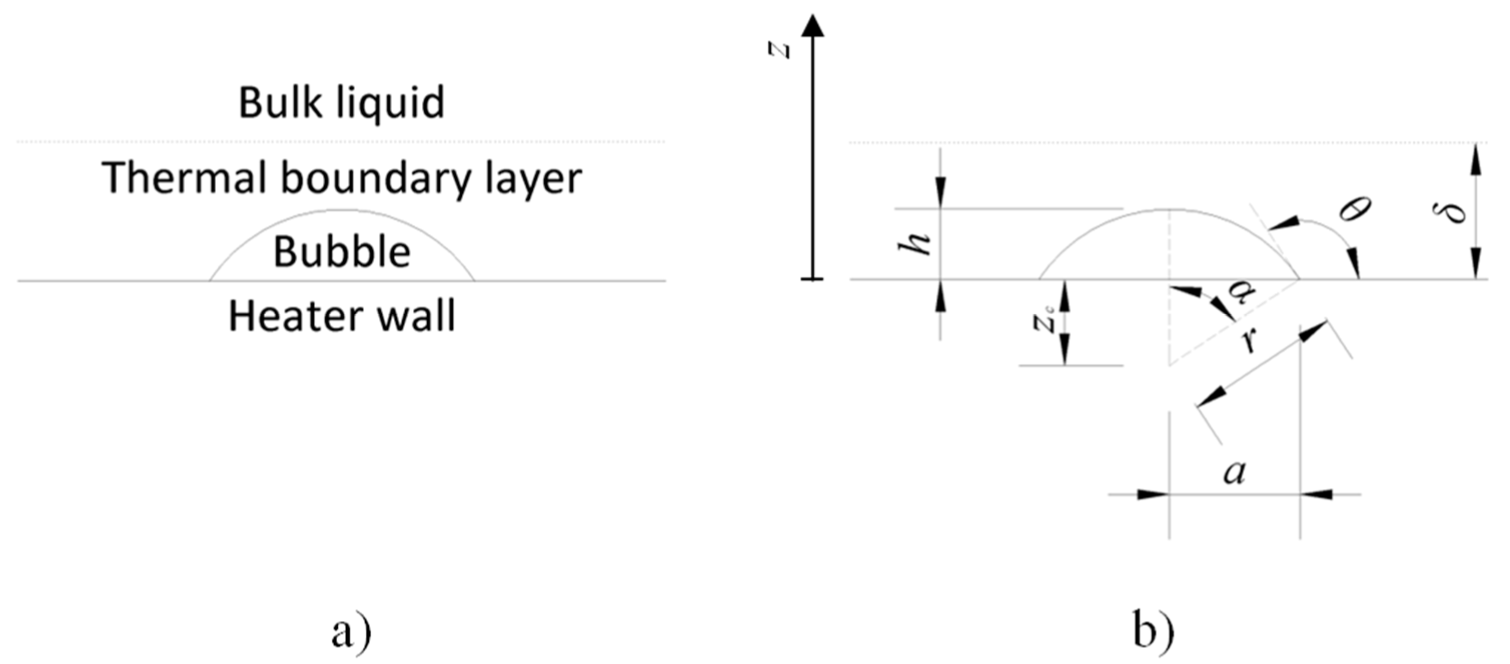
Figure 1. Schematic representation of a growing bubble (a) and its geometrical features (b).
Fluids 07 00090 g001
Figure 2. Scheme of the different heat fluxes, which affect the bubble growth in initial phase (a) and a later phase (b).
Fluids 07 00090 g002
Figure 3. Geometrical aspects of the bubble: radius (a), volume (b), geometrical angle (c) and contact angle (d) during its growth at q . t b l = 890 kW/m2.
Fluids 07 00090 g003
Figure 4. Geometrical aspects of the bubble (ac) and evolution of the bubble (d) during its growth at q . t b l = 890 kW/m2.
Fluids 07 00090 g004
Table 1. Bubble growth time and radius at detachment from the heater surface (rd) at varying heat flux from the thermal boundary layer.
q . t b l [kW/m2]tg [ms]rd [mm]
885>25.0>2.224
8909.21.349
8954.20.921
9003.40.827
9052.90.764
9102.50.717
9501.40.532
10000.90.437
Table 2. Bubble growth time and radius at detachment from the heater surface at varying heater wall heat flux.
q . w [kW/m2]tg [ms]rd [mm]
0>25.0>2.224
520.22.002
1015.51.755
259.81.399
509.21.349
1509.11.347
2509.11.343
5008.91.334
8907.91.258
Table 3. Bubble growth time and radius at detachment from the heater surface at varying heat flux from the spherical cap above the thermal boundary layer.
q . s c [kW/m2]tg [ms]rd [mm]
05.91.089
−0.17.11.188
−0.29.21.349
−0.317.21.847
−0.4>25.0>2.224
Table 4. Bubble growth time and radius at detachment from the heater surface at varying the thermal boundary layer thickness.
δ [mm]tg [ms]rd [mm]
0.29>25.0>2.224
0.309.21.349
0.312.20.664
0.321.50.560
0.331.30.505
0.341.10.471
0.351.00.448
Publisher’s Note: MDPI stays neutral with regard to jurisdictional claims in published maps and institutional affiliations.