1. Introduction
Gas-dynamic flows with phase transformations are ubiquitous in nature and technology. Condensation of water vapor contained in humid air can play a special role in the flow around aerodynamic surfaces. Condensate generation can affect the performance of steam turbines in power plants. Wet gas flow has a significant effect on the thrust characteristics of rocket engine nozzles. Many chemical processes take place at the phase interface. Using heterogeneous condensation, gas is purified from submicron particles.
In nature, there are two types of vapor condensation. The first type is homogeneous condensation, in which the initial condensation centers (nuclei) arise spontaneously from the vapors of the substance itself [
1,
2,
3,
4,
5,
6,
7,
8,
9]; the second type is heterogeneous condensation, when particles of another (usually solid) phase are the centers of condensation [
10,
11,
12,
13,
14,
15,
16]. Condensation of a binary gas mixture, in which vapors of one substance can condense on the nuclei of another substance [
17], is a special case of heterogeneous condensation. Heterogeneous nucleation associated with the initial adhesion of clusters to the surface of particles of another phase will be called activation.
The process of both homogeneous and heterogeneous condensation can be divided into two stages: the first is nucleation, and the second is the growth of droplets due to condensation. At the first stage, the majority of stable nuclei of a new phase are formed from the initial metastable phase (supersaturated vapor). The nucleation of a new phase occurs due to the high degree of metastability of the medium, and the end of the nucleation process is due to a decrease in the degree of metastability due to the transition of a part of the substance of the metastable phase into nuclei of a stable phase. At the stage of condensation growth of droplets, the size of droplets (nuclei) of a new phase increases with a constant number of droplets.
Depending on the role of other phase particles, nucleation can occur either through homogeneous nucleation or through heterogeneous activation.
Heterogeneous nucleation is determined by such factors as the size distribution of solid condensation nuclei and their concentration, the concentration of vapor monomers at the core surface, and the activation energy of nucleation, which depends largely on the contact angle of wetting of the core surface liquid. Because there is lower energy consumption during activation than during homogeneous condensation, heterogeneous condensation leads to less supercooling of the mixture and a faster approach to equilibrium. It can be assumed that if the probability of nucleation is higher near foreign bodies than in other parts of the medium, then the condensation process proceeds according to a heterogeneous type. However, if there are not enough foreign particles (or if they are absent), then condensation is homogeneous during the transition from a metastable state to a stable. As a rule, heterogeneous nucleation occurs at earlier stages of undercooling (at lower parameters characterizing the metastability of the medium) than homogeneous nucleation. However, in many natural phenomena and some technical devices, due to the different flow conditions in the flow, the joint occurrence of both condensation processes is possible.
In recent years, the problems of the numerical modeling of homogeneous [
18,
19,
20,
21,
22,
23,
24,
25] and heterogeneous condensation [
26,
27,
28] have been actively studied. The problem of the joint occurrence of heterogeneous and homogeneous nucleation in solutions and melts was considered in [
29], and in gas mixtures in [
30].
In the equation for the nucleation rate obtained in the classical heterogeneous nucleation theories [
31,
32,
33], a coefficient is introduced into the exponential function. This coefficient is defined as an interfacial correlation function
f. With this approach, previously proposed in [
34], the free energy of the formation of the critical embryo on the nucleating particle at a given supersaturation is defined as the product of the free energy barrier of homogeneous nucleation and the interphase correlation function
f. Heterogeneous nucleation corresponds to low values of
f and small values of supersaturation, homogeneous nucleation corresponds to high values of supersaturation and
. The
f value is determined by the interfacial tension between different phases and the average radius of the foreign particles divided by the critical radius of the embryos.
The dynamics of the condensation process are described by the general dynamic equation (GDE) [
20], which sets the law of evolution of the size distribution function of liquid phase droplets. Solving this equation requires significant computational resources to store and work with multidimensional data sets. One of the most widely used approaches to solving GDE is the transition from a differential equation for the distribution function to a system of integrodifferential equations for the moments of this distribution function. The resulting system of equations requires closure. Hill [
18] was one of the first to propose a practical model based on the method of moments (MM). He proposed a form of moment equations that was applicable to any level of droplet growth by approximating the average droplet growth rate. The moment method was further developed in [
21,
22].
From the point of view of a mathematical description, heterogeneous nucleation (activation) differs from homogeneous nucleation by a function that sets the rate of nucleation. For condensation, the deposition of vapors on foreign clusters is energetically more preferable than the formation of new ones of their own. Fletcher was one of the first to propose the form of the nucleation rate function for spherical particles [
34]. This approach is preferable for considering heterogeneous cluster formation on relatively large particles. An alternative approach is an assumption that the particles are wetted entirely at once. This approach is called the instantaneous-wetting model [
28] and gives good results for droplets of the order of tens of nanometers. The model makes it easy to adapt MM for heterogeneous condensation.
For the closure of the system of moment equations in MM, it is essential to assume that the droplet growth rate has a constant or linear dependence on the radius. With more complex dependences of the droplet growth rate on the radius, the use of MM is difficult. To eliminate this drawback of MM in 1997, McGraw [
21] proposed a modification of MM, the quadrature method of moments (QMOM), with which the moments of the distribution function are tracked in time in the same way as in the usual case, but for which the exact closure requirement is replaced by the approximate closure, which allows the method to be applied to a much wider range of cases.
In 2011, Yuan and Fox [
35] published the conditional QMOM (CQMOM) method. This method is more common and is applicable for modeling general problems by tracking the moments of the droplet size distribution function with an arbitrary number of internal parameters.
The efficiency of QMOM was studied in [
36,
37] when studying the process of primary and secondary nucleation in the transonic flow in a low-pressure steam turbine. The stability of QMOM is shown in the case of the calculation of condensation processes for a polydisperse distribution of droplets with sizes differing by several orders of magnitude.
In most of the computational cases considered in this work, droplets grow in the free molecular regime. Therefore, we assume that the droplet growth rate does not depend on the droplet radius [
21] and apply the standard MM approach.
In this work, we propose a mathematical model for studying the joint occurrence of heterogeneous and homogeneous condensation processes in technological devices. An approach based on the use of the moment method for modeling homogeneous and heterogeneous condensation is considered and supplements the study [
26] in part of the model of heterogeneous evaporation. In this paper, we propose to use the initial distribution function of dry particles during denucleation and to perform denucleation when the size distribution function of droplets (wetted particles) reaches the initial distribution function of dry particles. This distinguishes our model from previous works [
25,
38,
39], in which the critical drop nucleus was used for evaporation.
2. Physical and Mathematical Models
Often in applications, problems arise when homogeneous and heterogeneous condensation is realized simultaneously in gas-dynamic flows [
40]. In cases where the degree of supersaturation
S has very large values [
29,
30], homogeneous condensation prevails in the medium. The embryos are formed mainly from vapor molecules even when the number of foreign particles is insufficient for the heterogeneous condensation.
Unlike homogeneous condensation, heterogeneous condensation occurs on already-existing impurities: drops of another already-condensed gas, soot, or other small particles that act as condensation nuclei. For homogeneous condensation, we consider the condensation process as having two successive stages: nucleation and droplet growth. However, in contrast to homogeneous condensation, heterogeneous nucleation occurs due to an increase in the number of nuclei into which stable clusters of a condensing liquid, with a size greater than the critical size, nucleate (attach).
The physical model in this study is a multiphase medium consisting of a multicomponent gas (carrier gas/air and vapors of a condensing substance/water), and clusters (drops) of a condensing substance and solid foreign particles.
When constructing a mathematical model of the flow of a multiphase mixture with phase transitions, we use the following assumptions:
- (1)
Volume fractions of liquid and solid phases are negligible.
- (2)
Homogeneous droplets are in mechanical and thermal equilibrium with the gas phase. There is only mechanical equilibrium between heterogeneous droplets and the gas phase, that is, they have their own temperature.
- (3)
There are no collisions between drops.
- (4)
Diffusion between the vapors of the condensing substance and the carrier gas are neglected in the equations for the mass fractions of the condensing substance.
In addition, in our model, we suppose:
- (1)
Condensation occurs in two stages. As in the homogeneous case, the first is the nucleation stage, the second is the growth of droplets;
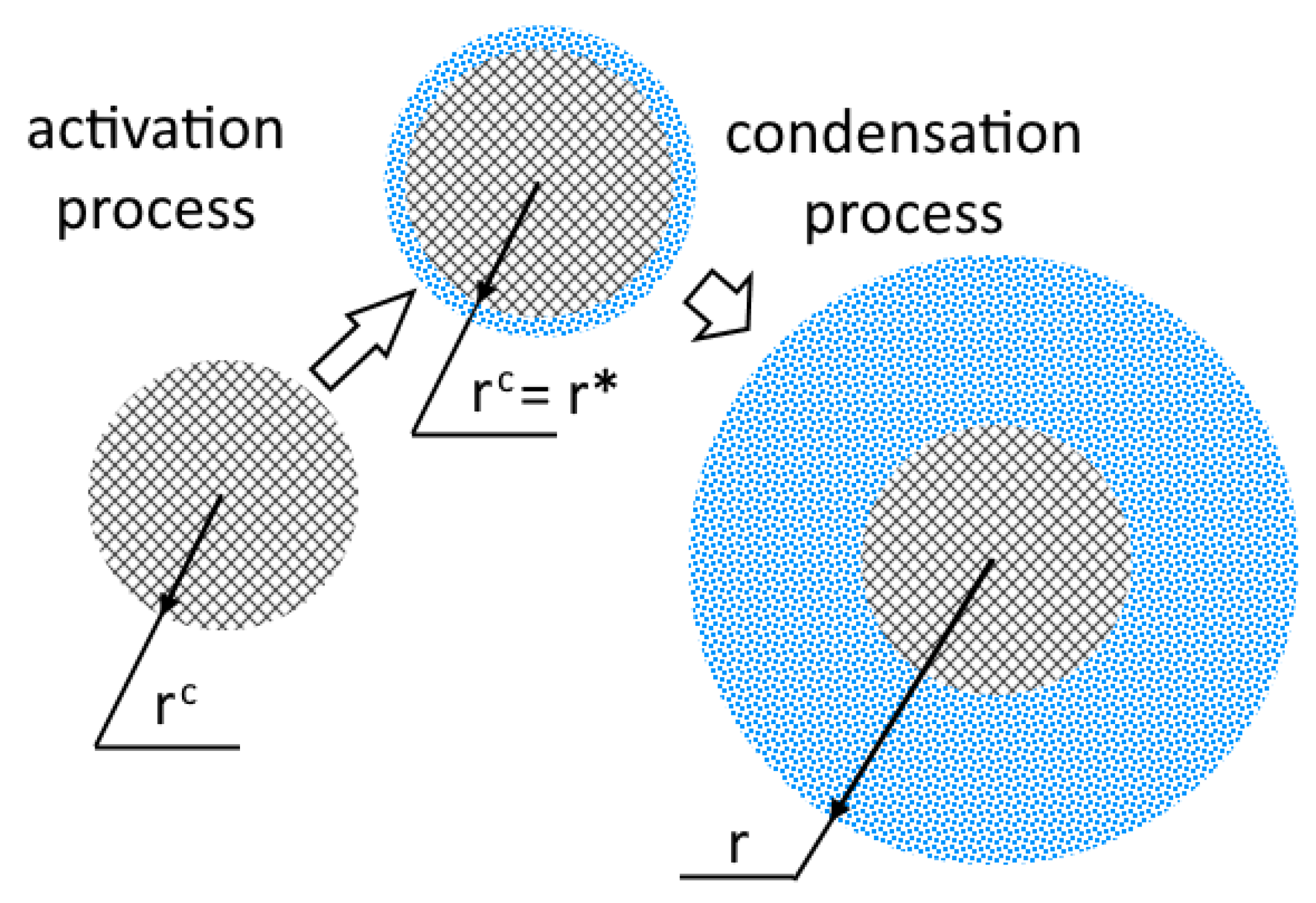
- (2)
The solid particle is completely covered with moisture at once (
Figure 1);
- (3)
The particle size distribution function for solid particles is known in advance and does not change;
- (4)
The growth of the droplet is uniform in all directions.
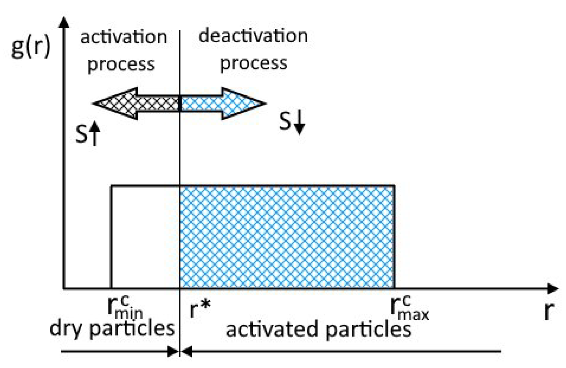
Figure 1.
Schematic representation of the heterogeneous condensation process, inspired by [
26].
Figure 1.
Schematic representation of the heterogeneous condensation process, inspired by [
26].
Furthermore, we assume that the activation of particles occurs only for particles of which the radius is greater than the critical radius of the nucleus
(
Figure 2) and that the rest of the particles do not participate in the process.
Figure 2 shows the particle size distribution function
. The arrow indicates the direction of propagation of the boundary of the activated particle with increasing supersaturation.
To describe the model of homogeneous-heterogeneous condensation, we assume that homogeneous condensation occurs only when the number of formed heterogeneous clusters is insufficient for the medium to pass from a metastable state to a stable one, only due to the formation of heterogeneous nuclei.
2.1. Model of Homogeneous-Heterogeneous Condensation
Within the framework of this approach, we use a system of equations that describes the dynamics of a viscous heat-conducting gas-droplet medium and an extended system of moment equations that describes phase transitions. Additionally, in this model, it is supposed that phase transitions according to homogeneous and heterogeneous types occur independently and therefore the system of moment equations can be represented as a combination of two systems of moment equations:
Here Oxy is the cylindrical coordinate system; ρ is the density of the mixture; p is the pressure; T is the static temperature of the mixture; u is the velocity along the x direction; is the velocity along the y direction; E is the total energy per unit mass; μ is the viscosity coefficient; λ is the thermal conductivity coefficient; are the moments of the size distribution function of homogeneous droplets (—the number of clusters (drops), —the sum of the radii of all drops, —the sum of the squares of the radii of all drops in a kilogram of the mixture); are the moments of the distribution function of heterogeneous drops by size; is the mass fraction of water condensed in a homogeneous way (the mass of liquid water in a kilogram of the mixture); is the mass fraction of water condensed in a heterogeneous way; is the rate of homogeneous nucleation (the number of nuclei of critical size formed in a cubic meter per unit of time); is the critical nucleus radius, is the rate of droplet growth; are the components of the viscous stress tensor; and are the components of the heat flux. In the plane case, is 0, and in the axisymmetric coordinate system, is 1.
Effective viscosity and thermal conductivity are defined as the sum of the laminar
,
and turbulent
,
components:
To calculate the turbulent viscosity and thermal conductivity, an algebraic turbulence model [
41] is used.
Heterogeneous activation affects homogeneous nucleation through the terms contained in the right-hand sides of Equations (5)–(8):
where
is the rate of heterogeneous activation (the number of particles of the solid phase activated in a cubic meter per second), determined [
26] on the assumption that the existence of droplets less than the critical size is energetically unfavorable:
If the rate
is less than
, homogeneous nucleation does not occur; however, otherwise both the presence of homogeneous and heterogeneous condensation is possible. This condition is taken into account in Equations (5)–(8) using the coefficient
, calculated from the value of
from (19):
In Equations (9)–(12), the terms
on the right-hand sides, describing activation upon condensation and deactivation upon evaporation of heterogeneous droplets, are written as follows:
Here the value
is the deactivation rate.
For the case of a uniform distribution function of
foreign particles, with a particle size distribution from
to
, the rate of heterogeneous activation will have the following form:
where
is the total number of particles per unit mass for a dry mixture.
To calculate the derivative
, we used the values
on the current
k and the previous
k − 1 layers:
It should be noted that with an increase in the supersaturation S, the radius decreases and, as a result, the derivative will have a negative sign.
The physical model of the medium is a mixture of five components: a carrier gas, a vapor of a condensing substance and homogeneous drops of a condensing substance, heterogeneous drops of a condensing substance, and foreign solid particles. Quantitatively, each component is characterized by its mass fraction, that is, the ratio of the mass of the component in a kilogram of the mixture to the kilogram of the mixture, so that the sum of the mass fractions of all components is equal to one. For a correct representation of material balances (conservation laws) in a multiphase medium, it is necessary to use five equations in a mathematical model that describe the evolution in time and space of the mass fractions of five components. Other representations are also possible, for example, one equation describing the evolution of the mixture density (the continuity equation) and four equations for describing the evolution of the mass fractions of four components. The mixture density is defined here as the ratio of a kilogram of the mixture (the sum of the mass fractions of the components multiplied by the kilogram) to the volume occupied by this mixture. In this work, the general system of equations contains:
- -
continuity Equation (1) (for the mixture density);
- -
Equation (8) for describing the evolution of the mass fraction of the liquid phase in homogeneous droplets;
- -
Equation (13) to describe the evolution of the mass fraction of the condensing fraction (that is, the sum of the mass fractions of the liquid fraction in homogeneous and heterogeneous droplets and the vapor fraction , where is the mass fraction of the vapor of the condensing substance—water);
- -
Equation (12) for describing the evolution of the mass fraction of the liquid phase in heterogeneous droplets; and
- -
Equation (14) for describing the evolution of the mass fraction of the solid phase .
Thus, for a correct description of the inhomogeneity of a multiphase medium, the equation for the propagation of the mass fraction of the condensing phase in homogeneous condensation (13) and the propagation of the mass fraction of the solid phase (14) was introduced. The addition of these equations to the general system (1)–(22) makes it possible to expand the class of flows with condensation that can be calculated. For example, this allows us to consider problems in which, in the initial distribution of parameters in different zones in the computational domain, different content of the condensed matter and solid particles is specified, or the flow in channels with a time-varying value of and on input.
Since the system of basic Equations (1)–(22) implements the assumption that different types of condensation occur separately, which can lead to a situation in which the reconstructed particle size distribution function will have a bimodal form. Both condensation processes proceed with different intensities and can be separated in time.
2.2. Determination of the Parameters of the Homogeneous Nucleation
In [
18,
31,
32,
33,
34,
42], the dependence of the nucleation function on correcting factors that take into account the curvature of the drop, the stationarity of the process, and the onset of the nucleation process was obtained:
where
is a correction factor introduced to take into account the nonstationarity of the process [
43],
β is the condensation coefficient;
;
is the surface tension of a flat film;
is a correction factor that takes into account the curvature of the drop;
b is a factor correcting the onset of nucleation;
is the supersaturation parameter;
T is the temperature of the medium;
L is the specific heat of condensation;
is the isentrope of the mixture;
is the gas constant for water vapor;
R is the universal gas constant;
is the density of the liquid phase; and
m is the mass of the molecule of the condensing substance (water).
It is assumed that only those particles are activated which have a radius less than the critical radius of the particles
, which is found from the condition of the maximum of the thermodynamic barrier:
2.3. The Growth Rate of Homogeneous Droplets
Two different models are used to determine the growth rate of homogeneous and heterogeneous droplets. To calculate the growth rate of homogeneous droplets, the Hertz–Knudsen model is used:
is the saturation pressure on the surface of a drop of average size radius.
β is the condensation coefficient.
The Gyarmathy model is used to calculate the growth rate of heterogeneous droplets [
44]:
where
is the Nusselt number for the heat flux,
is the droplet temperature, and
L is the specific heat of condensation.
To find the droplet temperature
, it is necessary to use implicit relations (27). The implicit computation of temperature is a very computationally expensive procedure. However, there is an approximate explicit formula for the calculation, which has a small error at a small saturation ratio [
42]:
where
where the coefficient
θ is calculated from the following expression:
is the modified diffusion coefficient equal to
, where
is for water.
For the Nusselt numbers
,
,
the following relations are valid:
Smolders [
28] proposed an approximate version of formulas (29) and (30) in the case of water condensation and selected for the continuous Nusselt numbers
, the values of
and
.
2.4. Closing Relations
We assume that the mixture is in thermodynamic equilibrium. In contrast to the cases of homogeneous and heterogeneous condensation, the combined model takes into account the presence of the mass fraction of the solid fraction in the flow of the multiphase mixture. The thermodynamic parameters of the mixture are written as follows:
where
is the specific heat capacity of the solid fraction;
,
are the specific heat capacities at constant volume and constant pressure for the carrier gas;
,
are the specific heat capacities for vapors of the condensing substance;
,
are the specific heat capacities for a two-phase mixture;
is the specific heat for the liquid; and
,
,
are gas constants of the carrier gas, vapors of the condensing substance, and the two-phase mixture.
The caloric and thermal equations of state are as follows:
where
is the speed of sound.
The mass fraction of water is calculated as the sum of the mass fractions of liquid
α formed in the homogeneous case and the heterogeneous case:
The molecular viscosity is calculated using the Sutherland law:
where
is the dynamic viscosity for
K,
K.
The rates of heterogeneous nucleation (activation) and denuclearization (deactivation) depend on the concentration of particles in the mixture; therefore, to calculate these values, it is necessary to know the mass concentration of foreign particles at each point of the computational domain.
2.5. Modeling Heterogeneous Evaporation and Denucleation
Evaporation occurs at
. In this case
and the droplet radius decreases. We assume that the deactivation of particles (their complete drying) begins when the droplet size reaches the initial values of the size of solid particles.
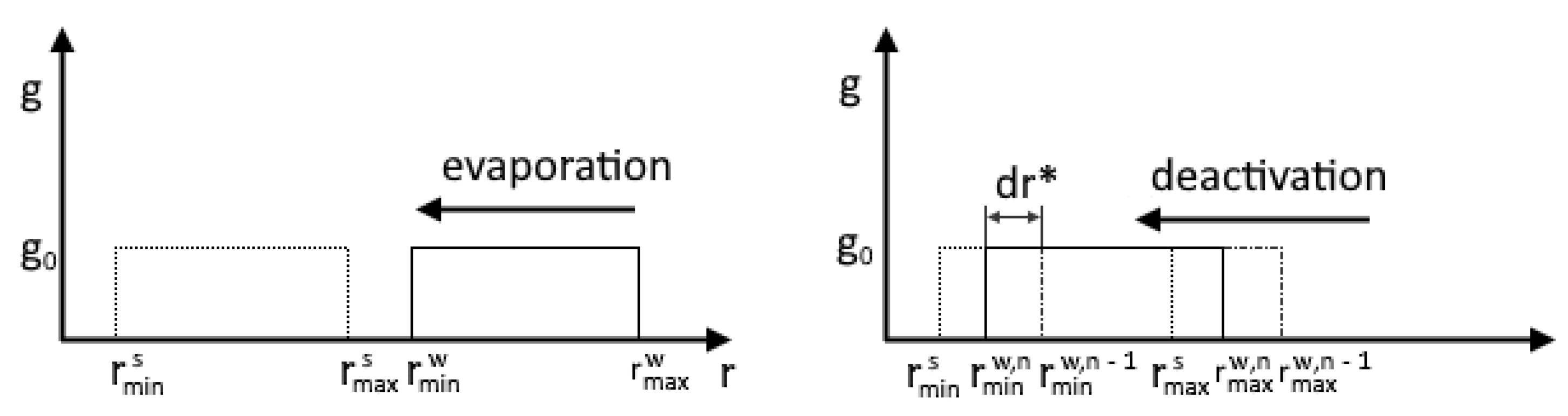
Figure 3 illustrates the processes of evaporation and deactivation using the example of a uniform distribution of foreign particles.
The deactivation process starts when the minimum radius of particles covered with a water film reaches the maximum radius of the spectrum of solid foreign particles. The particle deactivation rate is determined according to the ratio:
The main difference between the deactivation model (heterogeneous denuclearization) and the model proposed by Luo [
26,
38] is the calculation of the derivative of the droplet growth rate. To calculate this, the values of the minimum particle radii at the
n and
n − 1 layers are used:
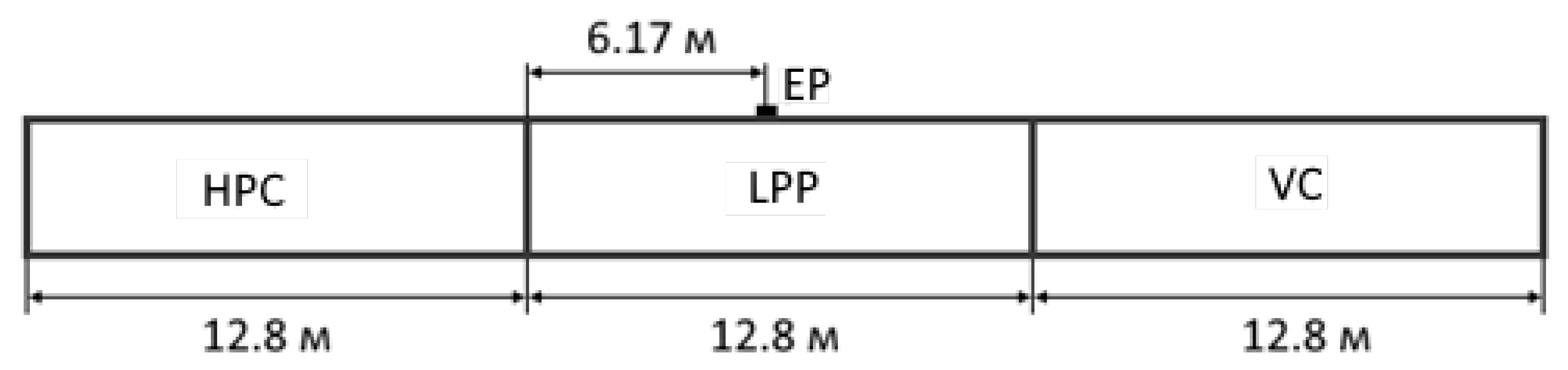
5. Numerical Results
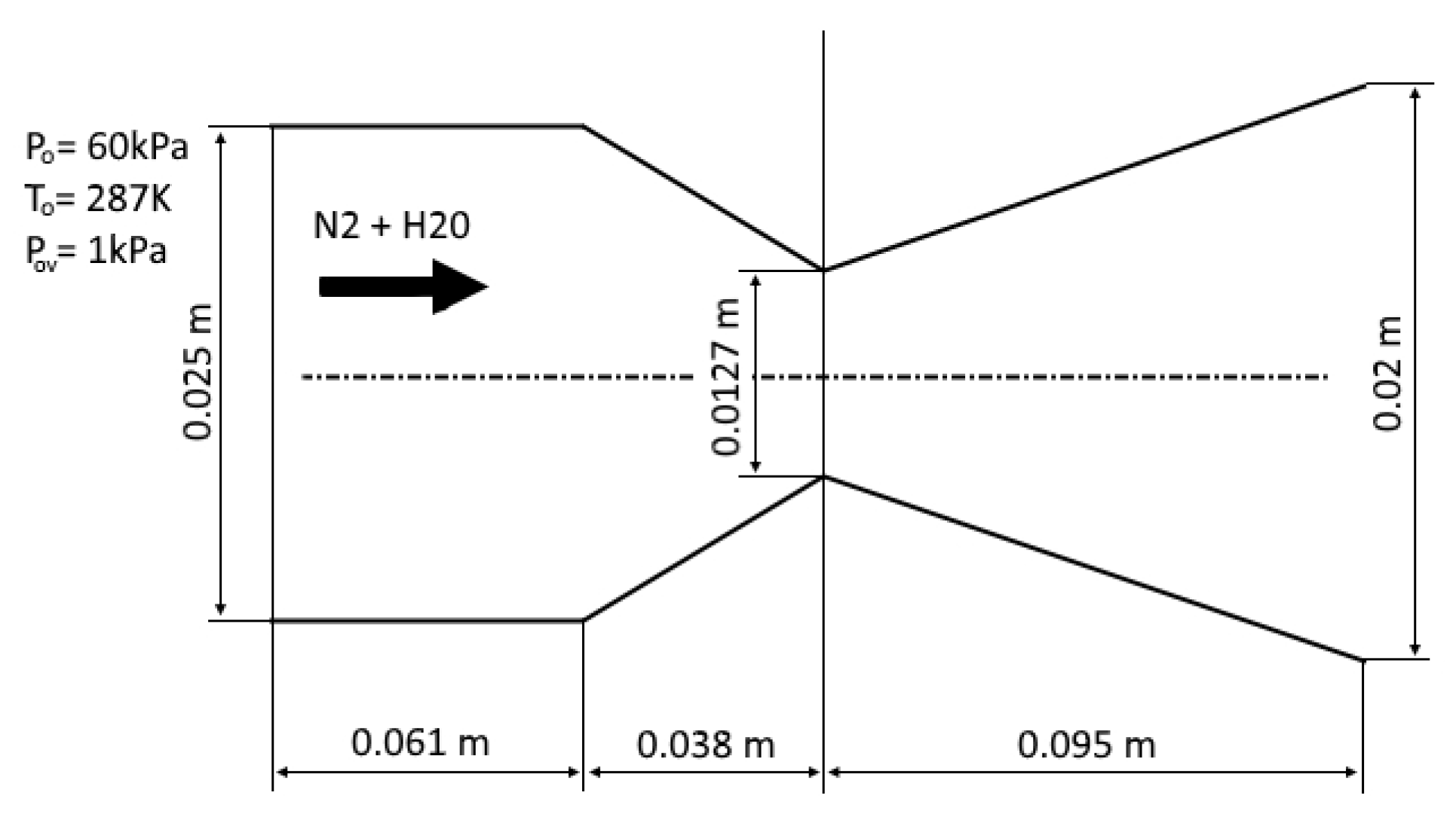
Using the developed algorithm, the numerical simulation of gas-dynamic flows with phase transitions in an ejector device for cleaning smoky gases is carried out. An overview of various ways of using ejectors is given in [
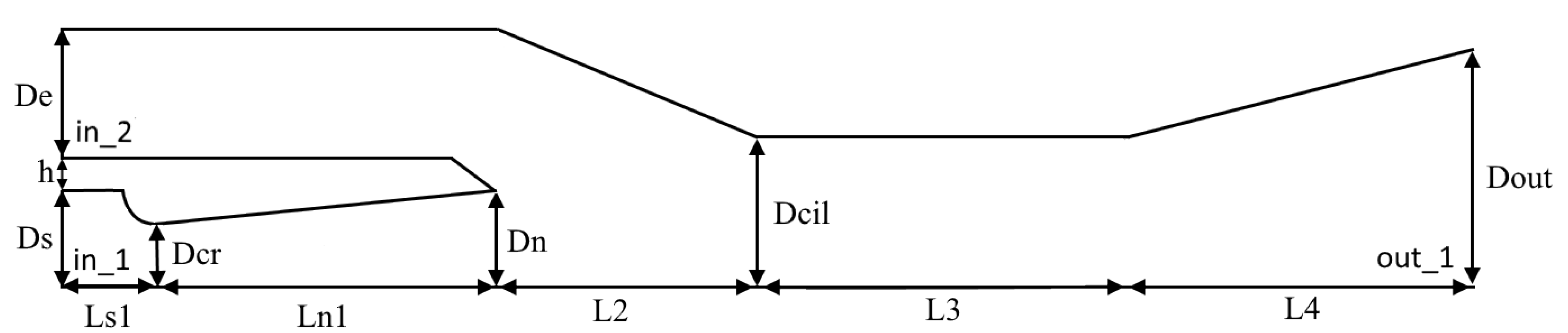
45]. The geometry of the calculated device consists of two coaxially located conical nozzles, as shown in
Figure 10. The corresponding dimensions are given in
Table 2. Water vapor comes from the area designated in_1 in the first nozzle and ejects air from the in_2 area of the second nozzle (
Figure 10).
In the numerical simulation, a block-structured computational grid is used. The grid has been adapted to the diffuser wall and the upper nozzle wall. The grid consists of about seventy thousand quadrangular cells.
We assume that the flow is turbulent. The algebraic turbulence model [
41] is used to calculate the turbulent viscosity and thermal conductivity.
The pressure and temperature values are set as input conditions at the boundaries in_1 and in_2. Constant pressure is set in the outer area behind the nozzle out_1. Values of temperatures and pressures are given in
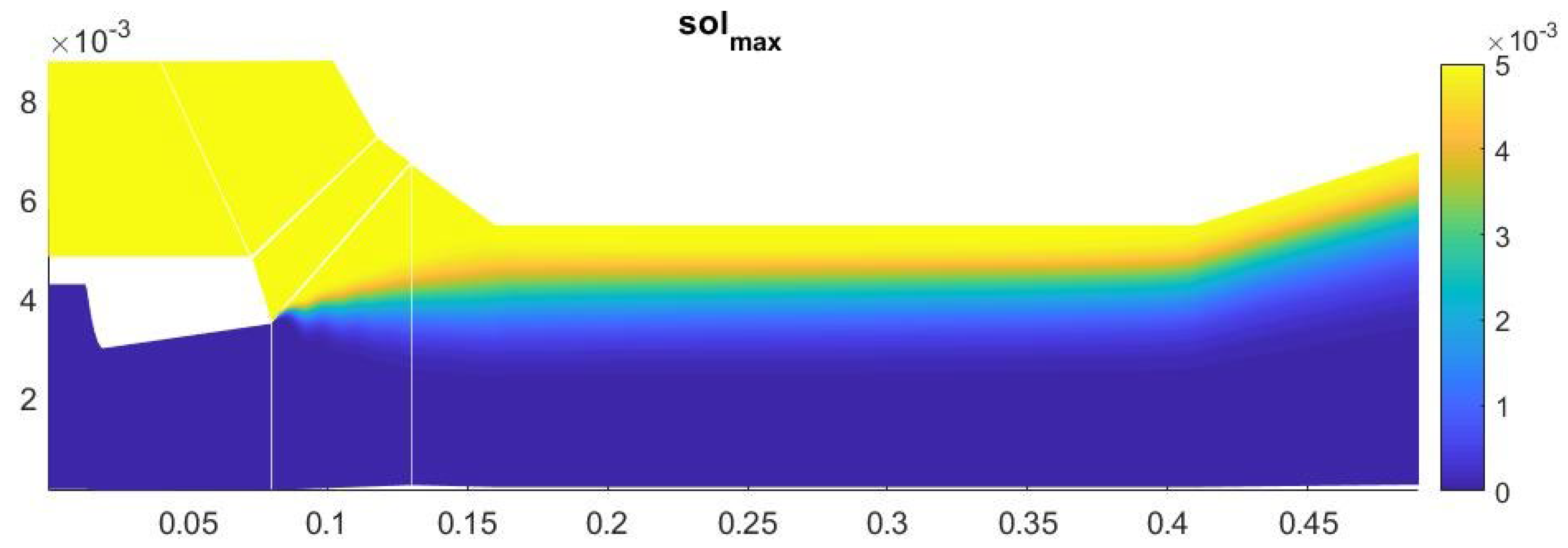
Table 3. The maximum concentration of solid particles of 50 nm in size was 0.005.
For efficient operation of the device, it is necessary that the flows of wet steam from the first nozzle and the ejected gas at the inlet to the second nozzle mix well in the mixing zone of the second nozzle, and as much condensate as possible should form in this zone. Therefore, to improve mixing in this system, a very long cylindrical part of the second nozzle is chosen. The first nozzle has a small degree of geometric expansion to prevent the formation of a large amount of condensate inside the nozzle.
To estimate the possible amount of condensate in the system, numerical simulation of the ejector operation was carried out for the case in which there are no foreign particles in the system and only homogeneous condensation occurs. The numerical calculation established the existence of three regions inside the ejector, where water condensate is actively formed. The first region is located inside the first nozzle, the second region is located directly behind the first nozzle, and the third region is in the diffuser of the second nozzle. In this case, the mass fraction of water condensate in the diffuser of the second nozzle reaches a value of 0.11. In numerical experiments, the ratio of injected gas to water vapor was about 25% at a water flow rate of about 120 L per hour. With the considered parameters of the problem, there were no zones of active evaporation of water droplets in the ejector.
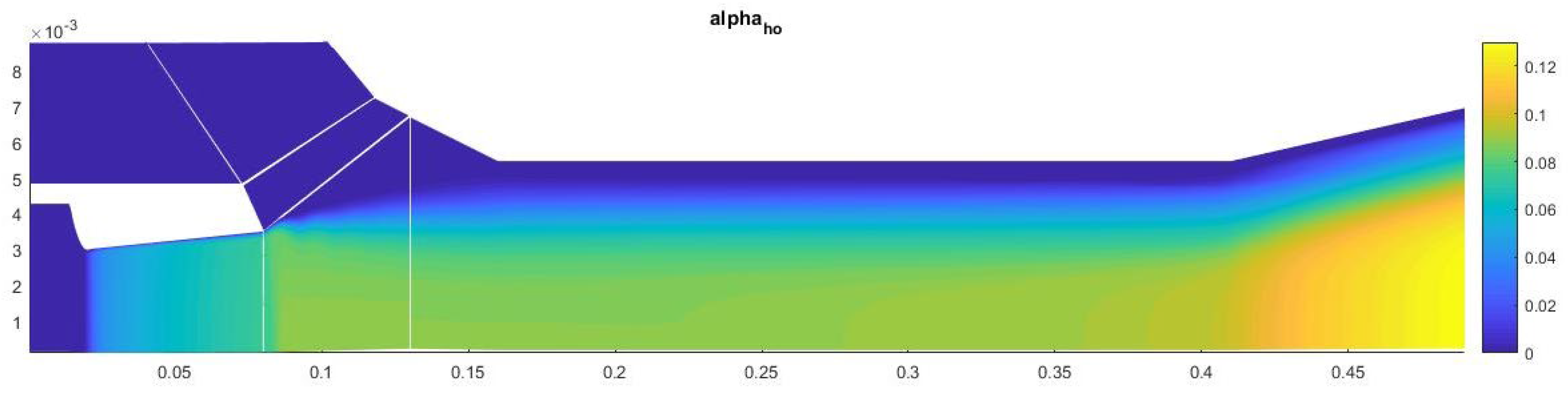
The results of numerical calculations show that there is no heterogeneous condensation up to the critical section of the second nozzle. However, as a result of mixing in the diffuser, it causes the appearance of heterogeneous condensation in the second nozzle. However, due to an insufficient degree of mixing (
Figure 11 and
Figure 12) and a low level of supersaturation in the second nozzle, heterogeneous condensation occurs much less intensively than homogeneous condensation.
The amount of condensate on the axis of symmetry in this case is about 13% (
Figure 13). Most of the heterogeneous condensation occurs in the mixing region near the wall of the second nozzle (
Figure 14). In the near-wall region, condensation occurs weakly due to an increase in temperature in the boundary layer.
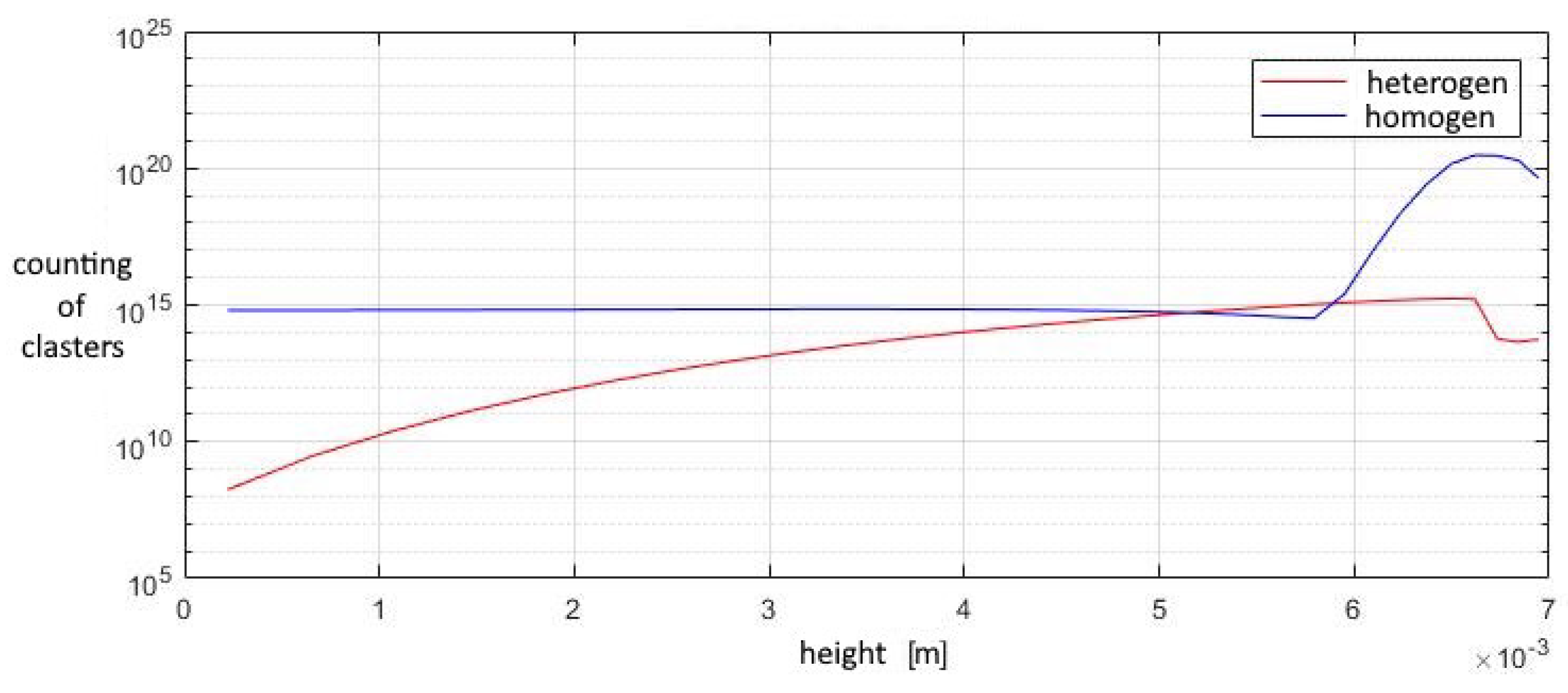
A study of the parameters at the exit from the second nozzle shows that in this device the number of homogeneous clusters is much higher than that of heterogeneous ones, which prevents the greater growth of heterogeneous droplets. This leads to the fact that the increase in the total volume of homogeneous droplets is higher than that of heterogeneous ones, at a lower growth rate of the droplet. Under such conditions, heterogeneous condensation is weakly manifested, which does not allow droplets on solid particles to grow significantly in size (
Figure 15,
Figure 16 and
Figure 17).
The contribution of heterogeneous condensation to the flow turns out to be insignificant. This is due to the small number of heterogeneous clusters. There are several orders of magnitude more homogeneous clusters. This leads to the fact that a small increase in homogeneous droplets causes a significantly greater increase in the amount of than for of heterogeneous wetted particles. The growth rate of heterogeneous clusters is insufficient to significantly increase the volume of water on the particles, and therefore the heterogeneous particles are too small for their further separation using centrifugal separators. However, coating the particles with water can increase the efficiency of electrostatic filters. An electric charge can cause even the smallest droplets to settle when using electric fields.
6. Conclusions
In this paper, we have proposed a mathematical model for the study of gas-dynamic multiphase flows with the simultaneous occurrence of phase transition processes.
An approach based on the use of the moment method for modeling homogeneous and heterogeneous condensation and evaporation is considered.
The system of equations for describing unsteady gas-dynamic processes based on the Navier–Stokes equations and equations of the method of moments for the phase transition processes in two-dimensional plane and axisymmetric cases has been expanded by adding two equations for the mass fractions of the condensing substance and the solid particles. This allows us to significantly extend the class of problems to be solved.
Using the developed algorithm, a numerical simulation of gas-dynamic flow with phase transitions in an ejector device for cleaning smoky gases has been carried out. Superheated steam is supplied to the inlet of the first nozzle and condenses in the supersonic part of the nozzle. A two-phase vapor-droplet mixture ejects dusty gas from the second nozzle and mixes with it. In the expanding part of the second nozzle of the ejector, heterogeneous condensation occurs on dust particles, which increases their mass. In the considered case, the size of the particles increases insignificantly, which prevents the separation of these particles due to centrifugal force. However, wetted particles can increase the efficiency of other cleaning methods, one example of which is an electrostatic filter.


