Article

Three-Dimensional Simulations of Viscous Incompressible Fluid Flows on Grids with Unmatched Grid Interfaces

1
Russian Federal Nuclear Center-All-Russian Research Institute of Experimental Physics, 607188 Sarov, Russia
2
Department of Applied Mathematics, Nizhny Novgorod State Technical University n.a. R.E. Alekseev, 603999 Nizhniy Novgorod, Russia
3
Moscow Aviation Institute, 125993 Moscow, Russia
*
Author to whom correspondence should be addressed.
Fluids 2022, 7(11), 346; https://doi.org/10.3390/fluids7110346
Submission received: 13 October 2022 / Revised: 2 November 2022 / Accepted: 4 November 2022 / Published: 9 November 2022
(This article belongs to the Special Issue Applications in Computational Fluid Dynamics)

Abstract

:
The paper describes a numerical method that considers specific computational fluid dynamics (CFD) aspects of viscous incompressible flow simulations in the vicinity of interfaces between unmatched fragments of unstructured grids. The method is based on the general grid interface (GGI) principle, which involves conservative flux interpolation and does not require original grid modification at unmatched interfaces. A method is presented which combines adjacent unmatched fragments of an unstructured grid into a single domain by means of virtual interfaces considering connections between adjacent cells through virtual faces. The performance of the method is illustrated by the finite-volume discretization of the transport equation in the region of matched interfaces and its modification for the case of unmatched interfaces. The efficiency of the proposed method is demonstrated by three-dimensional CFD simulations with grid models composed of unmatched unstructured grid fragments. The simulation results are compared with equivalent simulations on matched grids. The influence of unmatched interfaces on the convergence rate and accuracy of the solution is assessed.

1. Introduction

At present, demand for CFD simulations of industrial objects based on the solution of the three-dimensional Navier–Stokes equations and involving large-scale models has grown significantly. Examples of such applications are simulations in nuclear power engineering, shipbuilding, and aircraft engineering, as well as other simulations that model hydrodynamic flows in complex-geometry structures [1,2,3,4,5,6]. In most cases, such simulations are done on a single grid that can contain more than a billion computational points (cells). The generation of such grid models representing all the details of physical processes taking place in the computational model is a nontrivial and generally time- and resource-intensive task. Dividing a complex initial geometry into simpler fragments makes the task of grid generation much easier, provides higher-quality grids, and efficiently saves computational resources. For example, optional grid refinement in individual fragments delivers a more accurate solution without significantly increasing the cell count in the grid model. Such grid models are usually composed of unmatched grid fragments generally having a different number and position of nodes at their adjacent boundaries. CFD simulations on such grids cannot be performed by standard approaches and require special methods to be developed. A key feature of CFD simulations using such grid models is that the unmatched grid fragments must be combined into a single computational model by means of special unmatched grid interfaces. The main problem of the unmatched grid interfaces is that they are nonconservative, which may lead to an unstable solution or perturbations [7].
Among the grid interface matching approaches proposed in the literature, there are a number of algorithms that geometrically merge fragments of arbitrary unstructured grids into a single grid model [8,9,10]. This is done by the modification of the original grid and the transformation of interfaces into a set of inner faces. These methods keep the grid model calculations conservative, but the process of the geometric merging of arbitrary unstructured grids requires using a large number of computational geometry algorithms (exact positioning of new nodes, node merging, projection of resulting nodes to edges and faces, etc.) and does not exclude the risk of creating domains with “poor” cells, the quality of which falls beyond admissible criteria.
There is a different group of methods, the so-called buffer/zipper layer [11,12], which is based on the creation in the region of unmatched grid interfaces of an intermediate unstructured layer to link the unmatched grid fragments. These methods are also conservative in grid model calculations. The drawback of this group of methods is that they cannot be used with grid models containing arbitrary unstructured grids, which limits the range of their applications in industry-oriented simulations on arbitrary-geometry grids.
In terms of computational efficiency, the most attractive approach is to use conservative methods based on the interpolation of quantities in the region of the unmatched interfaces. Such methods neither modify nor reconstruct the original grid at interfaces, which makes their programming much easier. One such method is the “patched grid” [13], which is widely used in calculations on multidomain grids. The drawback of this method is that it requires a high-quality structured grid.
One of the interpolation-based methods for combining unmatched unstructured grid interfaces is the general grid interface (GGI) method [14]. The GGI algorithm does not require modifying the original grid and is based on the use of weights determined by the face area ratio of virtual faces created by face projection from one of the interfaces to the other. The GGI method formed the basis for the development and successful implementation of a method enabling computations of nonoverlapping moving grids [15]. The authors of the GGI method demonstrated the conservativeness of the GGI interface and its modifications, given that the weights satisfy some criteria, but did not demonstrate that such weights can be found in all cases (for example, for unmatched unstructured interfaces). The authors also did not describe the procedure of interpolation between the faces of unmatched interfaces, which requires additional algorithms.
This paper describes a numerical method, which considers specific aspects of solving the Navier–Stokes equations in viscous incompressible flow simulations in the vicinity of interfaces between unmatched arbitrary unstructured grid fragments. The method is based on the philosophy of the GGI method. As distinct from the latter, our method does not require calculating the weights because it creates an identical set of virtual faces at adjacent unmatched interfaces, which guarantees its conservativeness. We propose a method of interpolation between the faces of unmatched interfaces based on area averaging. This method makes it possible to combine adjacent unmatched grid fragments into a single domain by linking adjacent cells through virtual faces, which saves time for problem-solving.
The numerical methods presented in this paper are implemented within the Russian software package LOGOS [16,17]. The performance of our method is demonstrated by simulations of turbulent flows in a circular pipe with a sudden restriction and in a circular diffuser. Each of the simulations is done using grid models consisting of matched and unmatched unstructured grid fragments. The influence of the unmatched interfaces on the convergence rate and accuracy of the solution is assessed.

2. Mathematical Model and Numerical Method

2.1. Mathematical Model

We consider a mathematical model of an isothermal flow of a viscous incompressible fluid. Under the given assumptions, the flow is described by the Navier–Stokes equations in the following form [18,19]:
{ u = 0 , ρ ( u t + ( u ) u ) τ = p .
where ρ is the simulated fluid density, t is the time, u is the velocity vector of the averaged flow in three-dimensional Cartesian coordinates, τ = τμ + τt is the sum of the molecular and turbulent components in the viscous part of the stress tensor, p is the pressure, Γ is the diffusion coefficient, and φ is a scalar quantity.
The system of Equation (1) is solved by numerical integration on a finite-volume grid. As an illustration of the final-volume discretization of Equation (1), consider the discretization of the equation of transfer of scalar quantity φ:
ρ φ t + ρ ( u φ ) ( Γ φ ) = 0
The first term in (2) is an unsteady member, the second one is a convective member, and the next one is a diffusive member. To simplify our presentation below, we consider the diffusion coefficient Γ to be a constant. In the general case, the complete form for the discrete equivalent of the differential equation of transfer of the scalar quantity (2), considering the assumptions above, with the time member approximated by an implicit Eulerian scheme [20], for the reference volume (cell) P is given by:
ρ φ P φ P t - 1 Δ t V P + C P D P = 0 .
Here, φP is the scalar quantity at the center of cell P at the current time step, φ P t 1 is the scalar quantity at the center of cell P at the previous time step, CP is the convective member for cell P at the current time step, and DP is the diffusive member for cell P at the current time step.
In what follows, the method is described for the case of discrete equivalents of the convective CP and diffusive DP members for a matched interface and their modification for an unmatched interface.
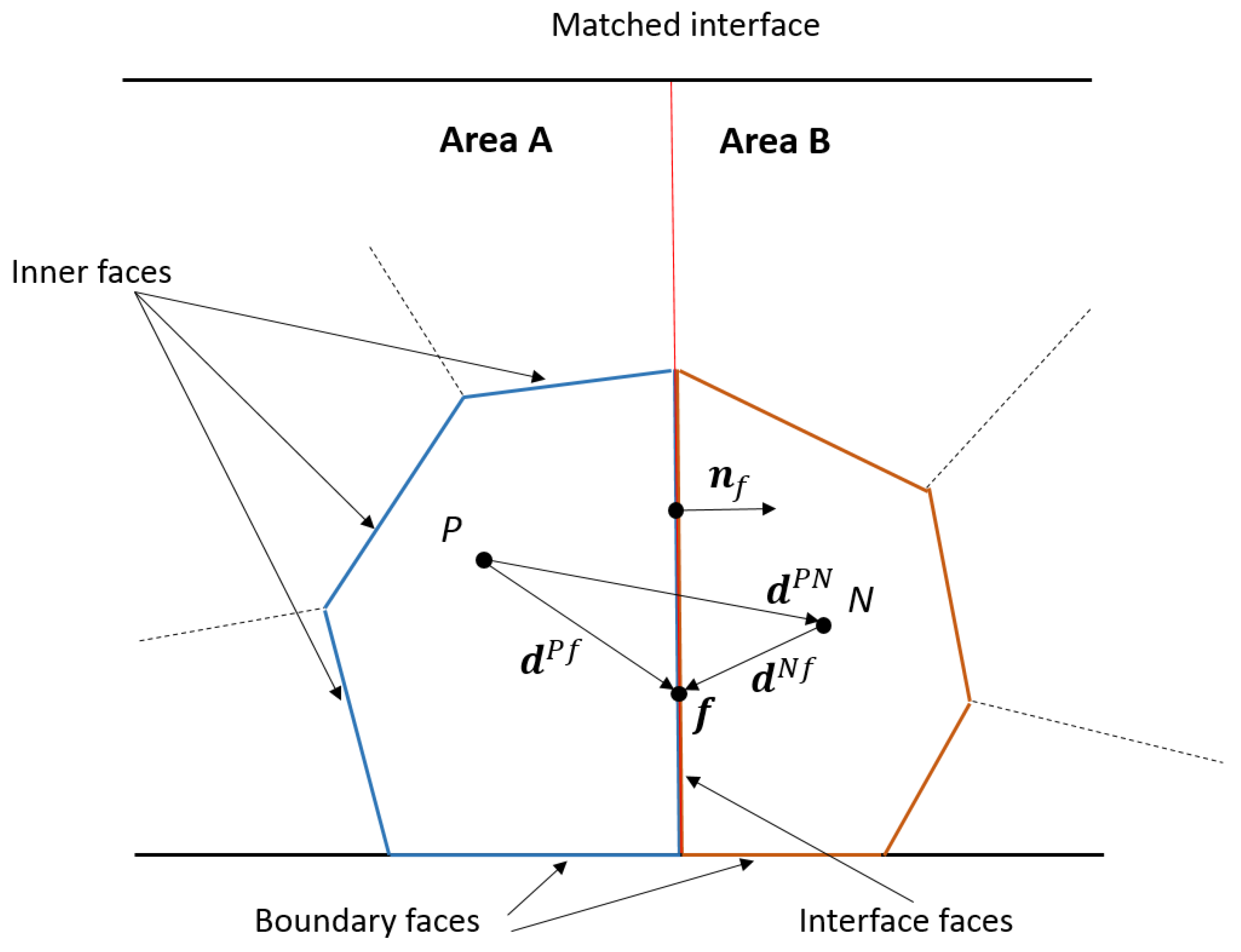
Consider a computational model composed of two grid fragments representing areas A and B, the adjacent boundaries of which fit each other in both the number and position of their nodes and create a pair of matched interfaces (Figure 1).
Approximated on the finite-volume grid, the convective and diffusive members at the current time step for cell P lying at the matched interface are given by
C P = f = f a c e ( P i n n e r , P b o u n d ) ρ φ f ( u f S f ) + f = f a c e ( P i n t e r f a c e ) ρ φ f ( u f S f ) ,
D P = f = f a c e ( P i n n e r , P b o u n d ) Γ ( φ f S f ) + f = f a c e ( P i n t e r f a c e ) Γ ( φ f S f ) ,
where Sf = Sf nf is the area normal to face f, Sf is the area of face f, φf is the scalar quantity at the center of face f at the current time step, uf is the velocity at the center of face f at the current time step, φf is the gradient of the scalar quantity on face f at the current time step, f = face(Pinner, Pbound) is summing over all the inner and boundary faces of cell P, and f = face(Pinterface) is summing over the interface faces of cell P.
The values of unknowns φf and uf for the inner and interface faces can be calculated by any of the known approximation schemes [18]. For the approximation scheme CD, the values of φf and uf are determined on face f assuming the linear variation in φf and uf between the centers of cells P and N (Figure 1), and are defined by
φf = λf φP + (1 − λf) φN,
uf = λf uP + (1 − λf) uN,
where the value of the geometric interpolation coefficient λf is defined as the ratio of distances fN and PN projected on face normal nf for cell P adjacent to cell N through face f (Figure 1), and is given by
λ f = | n f d N f | | n f d N f | + | n f d P f | ,
where dNf and dPf are the vectors constructed between the cell centers and face center f (Figure 1).
The calculations of the gradients on the faces of arbitrary unstructured grids are corrected for nonorthogonality [21]. The value of gradient φ f n on interface face f of cell P (Figure 1) at the n-th iteration of the current time step is defined by
φ f n = ( φ N n φ P n ) S f S f d P N + φ f n 1 ¯ ( φ f n 1 ¯ d P N ) S f S f d P N ,
where φ f n 1 ¯ = λ f φ P n 1 + ( 1 λ f ) φ N n 1 is the interpolated gradient of the scalar quantity on face f at the previous iteration.
In turn, gradient φP at the center of cell P can be calculated by the Green–Gauss algorithm [18] (the same is for cell N):
φ P = 1 V P f = f a c e ( P ) φ f S f ,
where f = face(P) is summing over all faces of cell P, including inner, boundary, and interface faces.
The discrete equivalent of the differential equation of transfer of the scalar quantity (3) can finally be represented as a system of algebraic equations, in which the following equation is constructed for each cell P in the domain (Figure 1):
a P φ P + a P N φ N + i = n b ( P ) a i φ i = b P ,
where aP is the diagonal coefficient of cell P, aPN is the nondiagonal coefficient relating cells P and N through the matched interface, ai are the nondiagonal coefficients relating cell P to the cells in domain A through common (inner) faces, bP is the right-hand member, and i = nb(P) is summing over all neighbor cells i having common faces with cell P.
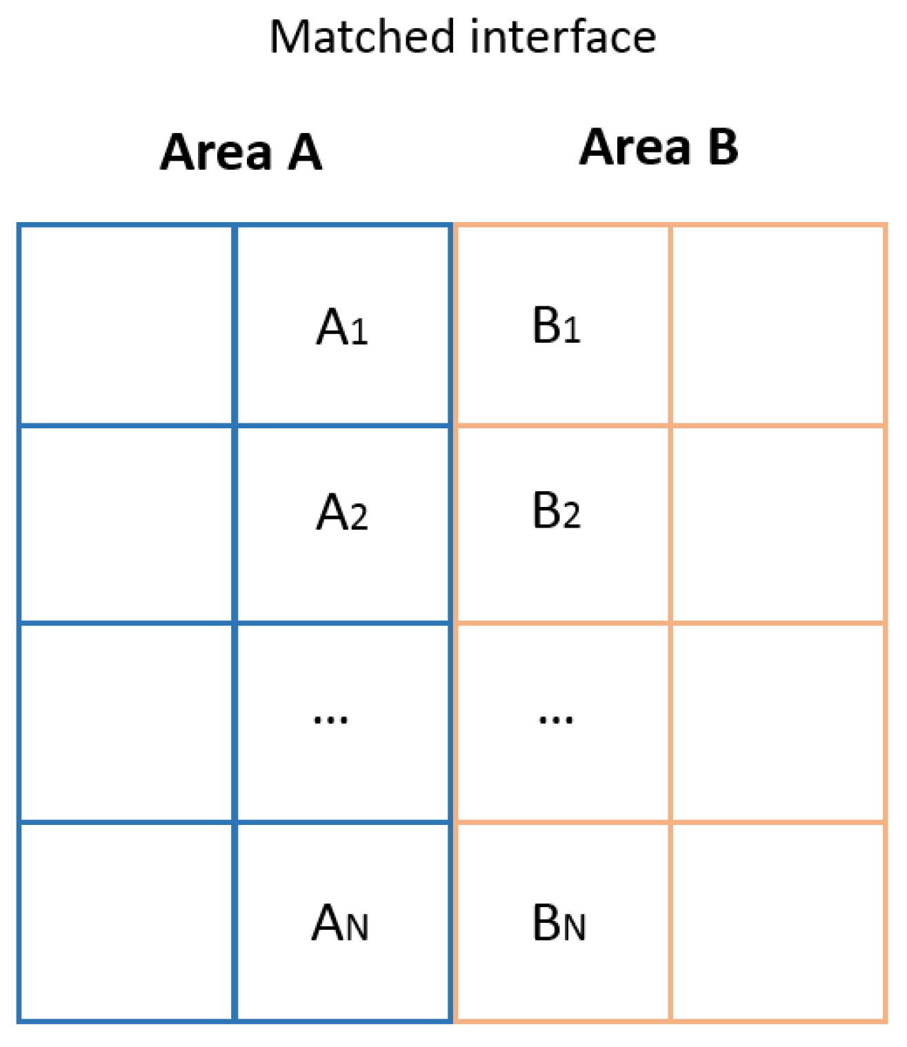
As a result, for the grid model composed of two matched domains A and B (Figure 2), a system of algebraic equations, (12), is developed, which can be solved by one of the iteration methods [22]:
( a A 1 0 a A 1 , B 1 0 0 a A N 0 a A N , B N a A 1 , B 1 0 a B 1 0 0 a A N , B N 0 a B N ) ( φ ) = ( b ) ,
where a A i , i [1…N] are the diagonal coefficients of the cells in area A, a B i are the diagonal coefficients of the cells in area B, a A i B i are the nondiagonal coefficients relating cells Ai to cells Bi through the interface faces, (φ) is the vector of the sought scalar quantity, and (b) is the vector of the right-hand member.
To simplify the presentation, we do not show the nondiagonal coefficients relating the cells through the inner faces in Equation (12). Let us write the diagonal coefficients in Equation (12) for the cells in area A (the same is for the cells in area B) without considering the boundary conditions at the n-th iteration of the current time step:
a A i = ρ φ A i n Δ t V A i + S i n n e r A i + S i n t e r f a c e A i ,
where the term S i n n e r A i is created due to the adjacency of cell Ai with the cells in area A through inner faces f:
S i n n e r A i = f = f a c e ( A i n n e r ) ( ρ λ f u f n S f Γ S f n f d A i A j ) ,
where Ai is the cell adjacent to cell Aj through the inner face, the term S i n t e r f a c e A i is created due to the adjacency of cell Ai with cell Bi through interface faces f:
S i n t e r f a c e A i = f = f a c e ( A i n t e r f a c e ) ( ρ λ f u f n S f Γ S f n f d A i B i ) .
The nondiagonal coefficients in the system of linear algebraic Equation (12) relating the cells in area A (the same is for the cells in area B) through the inner faces at the n-th iteration of the current time step are given by
a A i A j = f = f a c e ( A i n n e r ) ( ρ ( 1 λ f ) u f n S f + Γ S f n f d A i A j ) .
The nondiagonal coefficients in the system of linear algebraic Equation (12) relating cell Ai to cell Bi through the interface faces at the n-th iteration of the current time step are given by
a A i B i = f = f a c e ( A i n t e r f a c e ) ( ρ ( 1 λ f ) u f n S f + Γ S f n f d A i B i ) .
The coefficients on the right side of the system of linear algebraic Equation (12) for the cells in area A (the same is for the cells in area B) without considering the boundary conditions at the n-th iteration of the current time step are given by
b A i = ρ φ A i t 1 Δ t V A i + b A i i n n e r + b A i i n t e r f a c e ,
where b A i i n n e r and b A i i n t e r f a c e are given by
b A i i n n e r = f = f a c e ( P i n n e r ) Γ S f [ φ f ¯ n f φ f ¯ d A i A j n f d A i A j ] n 1 ,
b A i i n t e r f a c e = f = f a c e ( P i n t e r f a c e ) Γ S f [ φ f ¯ n f φ f ¯ d A i B i n f d A i B i ] n 1 .
The finite-volume discretization algorithm described above applies to all of the equations in (1). The method can be used in calculations of viscous incompressible flows on grid models of any dimensionality. However, the potential of its application is limited to calculations on models composed of a single grid or a grid composed of matched grid fragments. At present, this limitation makes the method much more difficult to use in most industry-oriented calculations, when grids are built of unmatched fragments to resolve details of specific physical processes. Such calculations require special interfaces, in which quantities φf, uf in (4) and (5), and quantities φf in (9) on the faces belonging to unmatched interfaces cannot be calculated by standard approximation schemes, and the neighborhood of cell P with several cells on the opposite interface must be taken into account.
Below we describe a modification of the numerical method, which considers specific CFD aspects of viscous incompressible flow simulations in the vicinity of interfaces between unmatched grid fragments.

2.2. Unmatched Interface Linking Method

We consider a computational model composed of two grid fragments representing areas A and B, the adjacent boundaries of which create a pair of unmatched interfaces (Figure 3). The unmatched interfaces are understood to be adjacent boundaries of unmatched grid fragments, in which the number and position of nodes are different in the general case.
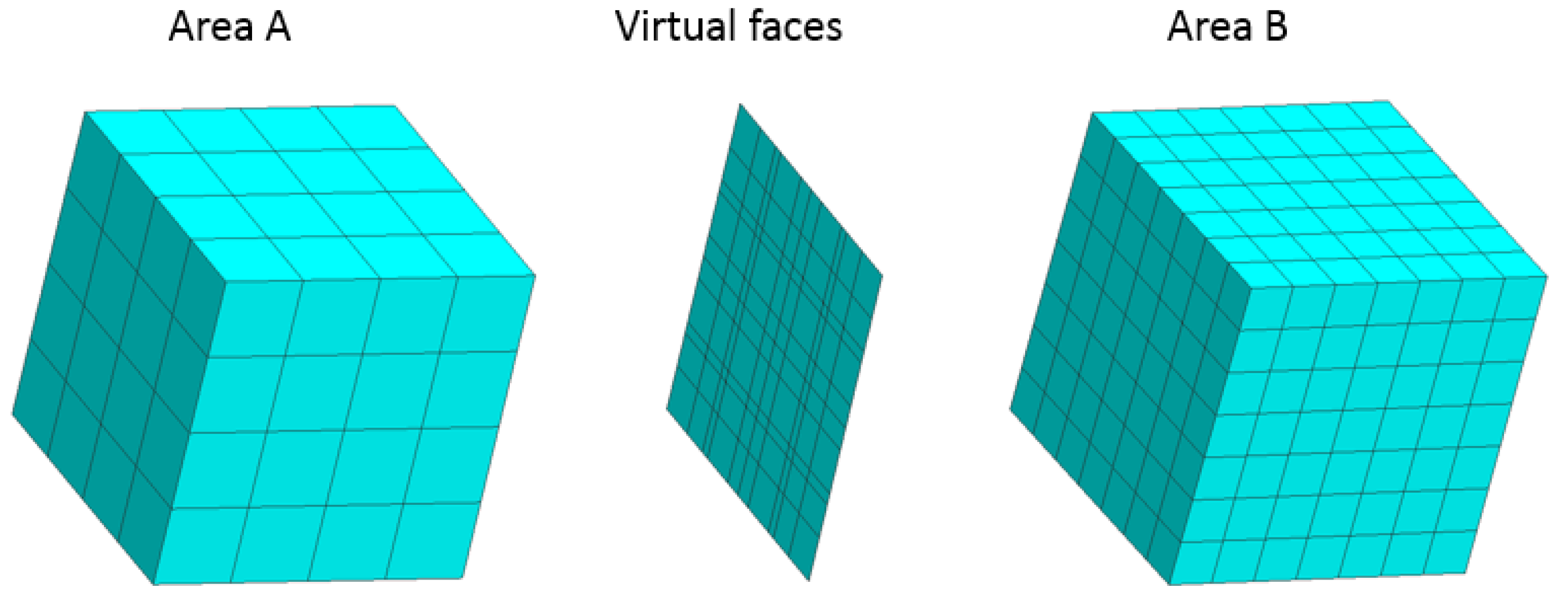
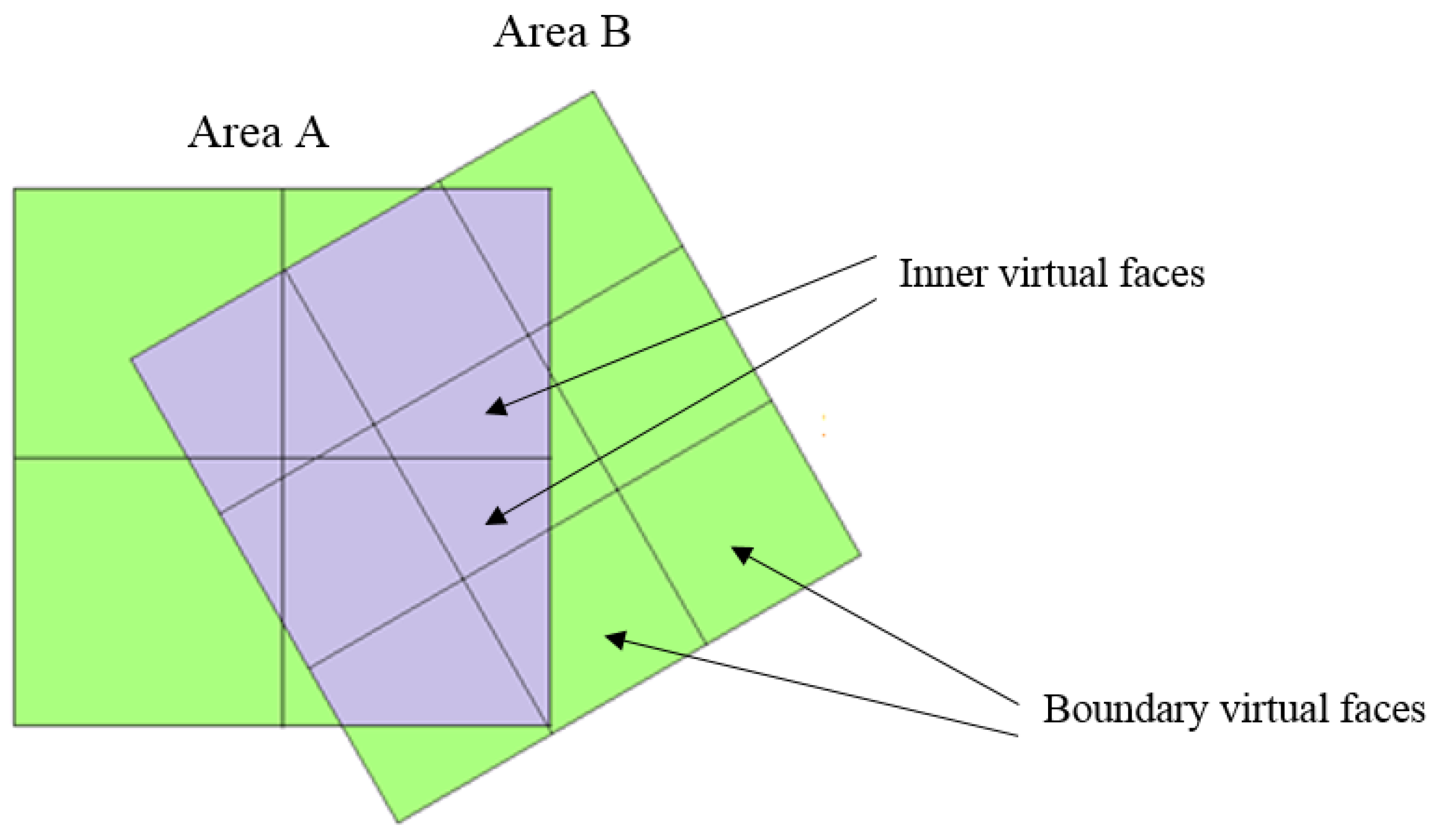
To merge the unmatched interfaces, the original faces are replaced by virtual ones. The geometric parameters of the virtual faces are determined by the successive projection of the original faces in area A to all of the original faces in area B. To identify the coordinates of the nodes created at the face intersections, one can use any of the polygon intersection algorithms [23]. The resulting set of virtual faces constitutes a virtual interface, which links the cells of the unmatched adjacent grid areas (Figure 3).
In the general case, the virtual interface consists of a set of inner and boundary virtual faces (Figure 4). The boundary virtual faces are not linked to the cells on the opposite interface and must be treated in accordance with the chosen boundary conditions. The inner virtual faces create a link between the adjacent cells on the interface.
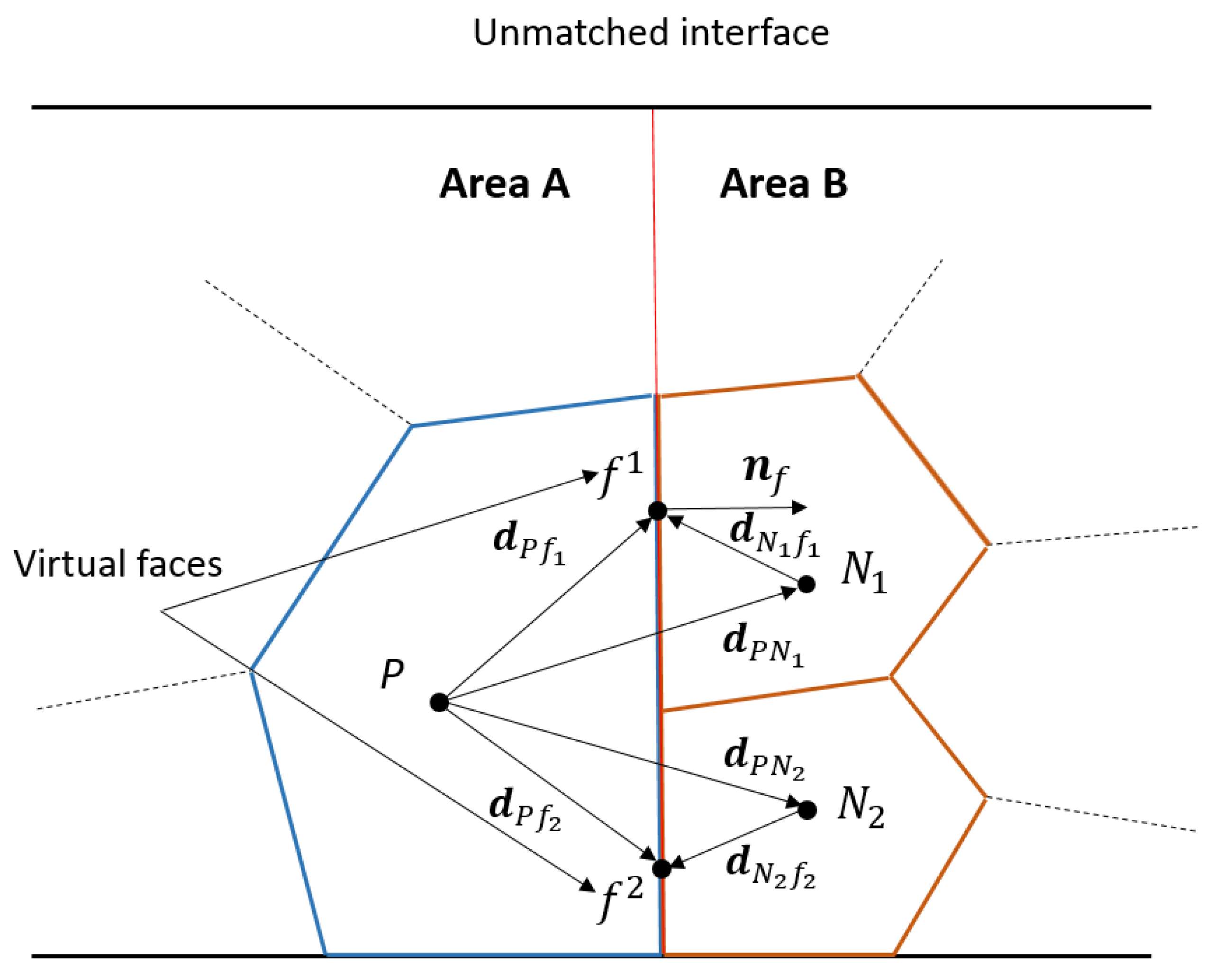
Consider the modification of the diffusive (4) and convective (5) members with a transition from the original to the virtual faces for the case of cell P belonging to the unmatched interface (Figure 5).
A discrete equivalent of convective member (4) for cell P belonging to the unmatched interface is expressed as:
C P = f = f a c e ( P i n n e r , P b o u n d ) ρ φ f ( u f S f ) + f = f a c e ( P i n t e r f a c e ) v ρ φ f v ( u f v S f v ) ,
where φ f v and u f v are the scalar quantity and velocity on virtual face fv created on original face f at the current time step, and S f v is the area of virtual face fv normal to original face f.
A discrete equivalent of diffusive member (5) for cell P belonging to the unmatched interface is expressed as:
D P = f = f a c e ( P i n n e r , P b o u n d ) Γ ( φ f S f ) + f = f a c e ( P i n t e r f a c e ) v Γ ( φ f v S f v ) ,
where φ f v is the gradient of the scalar quantity on virtual face fv.
The values of unknowns φ f v n , u f v n in (21) belong to the center of virtual face fv (Figure 5) and can be calculated by any of the known schemes [20]. For the approximation scheme CD, the values of φ f v and u f v are determined on face fv assuming the linear variation in φ f v and u f v between the centers of cells P and Nv (Figure 5) and are defined by
φ f v = λ f v φ P + ( 1 λ f v ) φ N v ,
u f v = λ f v u P + ( 1 λ f v ) u N v ,
where the value of the geometric interpolation coefficient λ f v is defined as the ratio of distances f Nv and P Nv projected on face normal nf for cell P adjacent to cell Nv through face fv (Figure 5), and is given by
λ f v = | n f d N v f v | | n f d N v f v | + | n f d P f v | ,
where d N v f v and d P v f v are the vectors constructed between the cell centers and face center f (Figure 5).
Considering the nonorthogonality correction, the value of gradient φ f v n on virtual face fv of cell P (Figure 1) at the n-th iteration of the current time step equals:
φ f v n = ( φ N v n φ P n ) S f v S f v d P N v + φ f v n 1 ¯ ( φ f v n 1 ¯ d P N v ) S f v S f v d P N v ,
where φ f v n 1 ¯ = λ f v φ P n 1 + ( 1 λ f v ) φ N v n 1 is the interpolated gradient of the scalar quantity on face fv calculated at the previous iteration.
The value of gradient φP at the center of cell P belonging to the unmatched interface is calculated by the Green–Gauss algorithm (the same is for cells Nv):
φ P = 1 V P ( f = f a c e ( P i n n e r , P b o u n d ) φ f S f + f = f a c e ( P i n t e r f a c e ) φ f a v S f ) ,
where φ f a v = v φ f v S f v v S f v is the averaged value of the scalar quantity on interface face f.
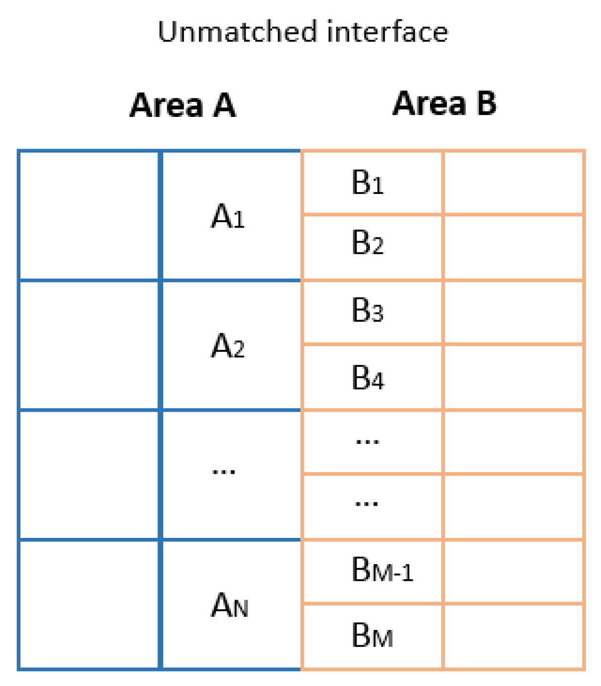
As a result of the above transformations, additional terms incorporating the link between the adjacent cells through the virtual faces are included in the discrete equivalent of the equation of transfer (11) for each cell P belonging to the unmatched interface (Figure 5). In the general case, for the grid model composed of two unmatched areas A and B (Figure 6), a system of linear algebraic equations, (28), is developed, which can be solved by one of the iteration methods [22]:
( a A 1 0 a A 1 , B 1 a A 1 , B 2 0 0 0 a A N 0 0 a A N , B M 1 a A N , B M a A 1 , B 1 0 a B 1 0 0 a A 1 , B 2 0 a B 2 0 0 0 a A N , B M 1 0 0 a B M 1 0 0 a A N , B M 0 0 0 a B M ) ( φ ) = ( b ) ,
where a A i , i [1…N] are the diagonal coefficients of cells Ai, a B j , j [1…M] are the diagonal coefficients of cells Bj, a A i B j are the nondiagonal coefficients relating cells Ai to cells Bj j through the virtual faces of the unmatched interface, (φ) is the vector of the sought scalar quantity, and (b) is the vector of the right-hand member.
To simplify the presentation, we do not show the nondiagonal coefficients relating the cells through the inner faces in the system of linear algebraic Equation (28). Let us write the diagonal coefficient in the system of linear algebraic Equation (28) for the cells in area A without considering the boundary conditions at the n-th iteration of the current time step (the same is for the cells in area B):
a A i = ρ φ A i n Δ t V A i + S A i i n n e r + S A i i n t e r f a c e ,
where S A i i n n e r is the term created due to the adjacency of cell Ai with the cells in area A through the inner faces, just as in (14), and S A i i n t e r f a c e is the term created due to the adjacency of cell Ai with cells Bi through the virtual faces of the unmatched interface:
S A i i n t e r f a c e = f = f a c e ( A i n t e r f a c e ) v ( ρ λ f v u f v n S f v Γ S f v n f d A i B i ) .
Nondiagonal coefficients a A i A j in the system of linear algebraic Equation (28) relating the cells in area A through the inner faces at the n-th iteration of the current time step are determined identically to (16).
The nondiagonal coefficients in the system of linear algebraic Equation (28) relating cells Ai to cell Bj through the virtual faces of the unmatched interface at the n-th iteration of the current time step are defined by
a A i B j = f = f a c e ( A i n t e r f a c e ) v ( ρ ( 1 λ f v ) u f v n S f v + Γ S f v n f d A i B j ) ,
where Bj, j [1…M] are the cells bordering on cell Ai through virtual faces fv.
The coefficients on the right side of the system of linear algebraic Equation (12) for the cells in area A (the same is for the cells in area B) without considering the boundary conditions at the n-th iteration are given by
b A i n = ρ φ A i t 1 Δ t V A i + b A i i n n e r + b A i i n t e r f a c e ,
where b A i i n n e r is determined identically to (19), and b A i i n t e r f a c e is given by
b A i i n t e r f a c e = f = f a c e ( P i n t e r f a c e ) v [ Γ S f v ( φ f v ¯ n f φ f v ¯ d A i B j n f d A i B j ) ] n 1 .
This method combines adjacent unmatched grid fragments into a single domain by means of created virtual interfaces and can be used for all equations in (1). It does not require the modification of the original grid and considers connections between adjacent cells through a set of virtual faces, which creates additional terms in the system of linear algebraic equations of the computational model. Thus, the calculations on models composed of unmatched computational domains by this method are equivalent to the calculations on matched computational models in terms of their computational expenses but are much less expensive in terms of the grid model construction.
In the section below, we illustrate the performance of our algorithm using simulations of a turbulent flow in a circular pipe with a sudden restriction, and in a round diffuser.
3. Numerical Experiments

Our method was implemented in the Russian software package LOGOS which is intended for three-dimensional heat and mass transfer simulations [16]. The performance of the method was demonstrated by numerical experiments which simulated widely known tests based on empirical calculations [24]. LOGOS had already been successfully verified by a series of test CFD calculations [25], so the numerical experiments were only aimed at comparing the results of calculations with identical models on the grids composed of matched and unmatched grid fragments.

3.1. Turbulent Incompressible Fluid Flow in a Circular Pipe with a Sudden Restriction

Let us consider how the method behaves in the numerical simulations of a turbulent incompressible fluid flow in a circular pipe with a sudden restriction [11]. The geometry of the computational model and the locations of control sections are shown in Figure 7. To test the method, the calculations were run on a matched and unmatched grid model.
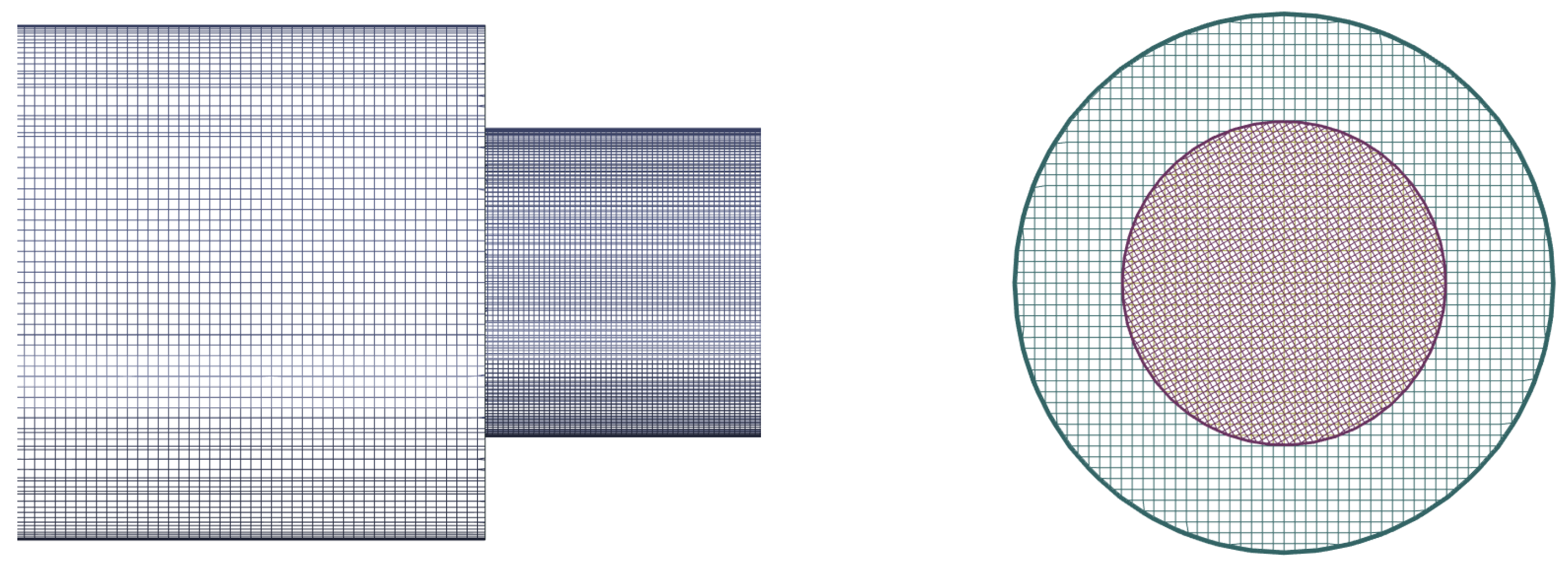
The unmatched grid model consisted of two unmatched fragments constructed independently by the pre- and postprocessor of the LOGOS software package. The unmatched grid fragments in the restriction area are shown in Figure 8. The matched grid model was constructed by the geometric merging of the unmatched grid fragments in the LOGOS pre- and postprocessor.
The governing parameters in the computational models included a fluid density equal to 998.2 kg/m3 and a dynamic viscosity equal to 0.00101 kg/(m∙s). Turbulence was modeled by the RANS SST turbulence model [26] with a 0.05 percent turbulence intensity and a 0.001 m mixing length. The convective members in the calculations were approximated by the first-order upwind scheme UD [18].
Figure 9 shows the boundary conditions of the computational models. The outer boundaries were impermeable no-slip rigid walls. The inlet flow rate was V = 0.4227 m/s. The outlet pressure was P = 0 Pa. Under set parameters, the flow Reynolds number was 20925. To match the solution in the unmatched model, we used the interfaces implemented in LOGOS in accordance with the method described above (Figure 9). For the nonintersecting interface area, the impermeable no-slip wall boundary condition was used.
The calculations were performed by LOGOS in a steady setup on 80 parallel processors up to a convergence in mass in the order of 10−6 kg. The iteration convergence graph is shown in Figure 10.
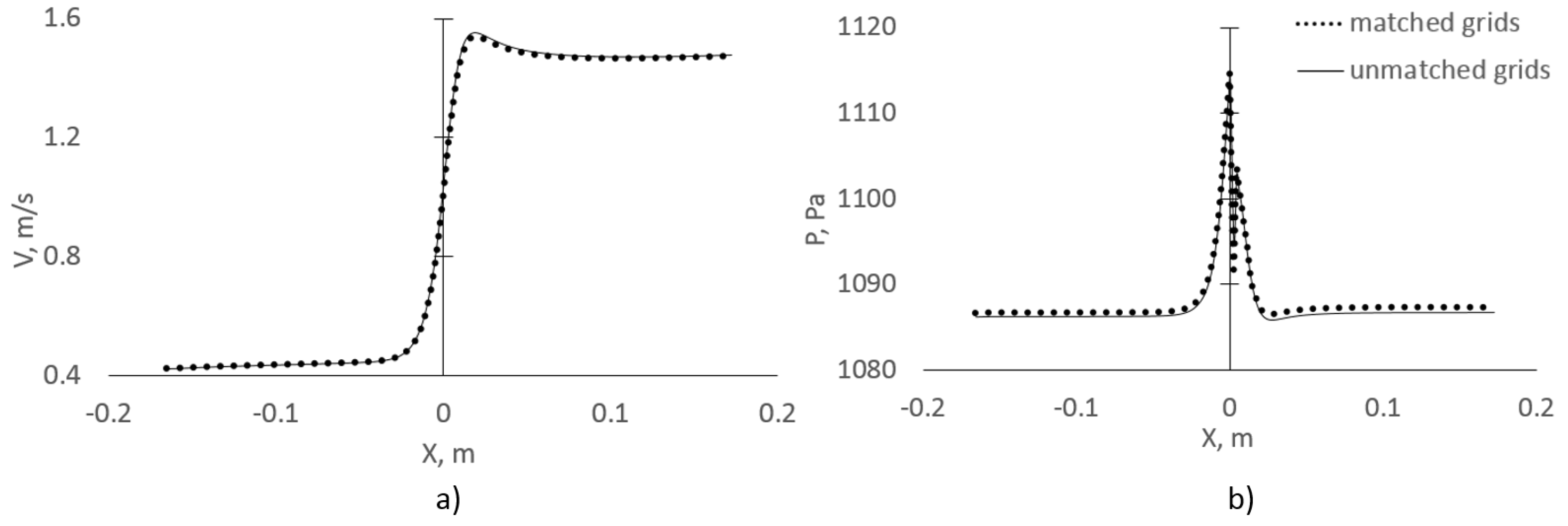
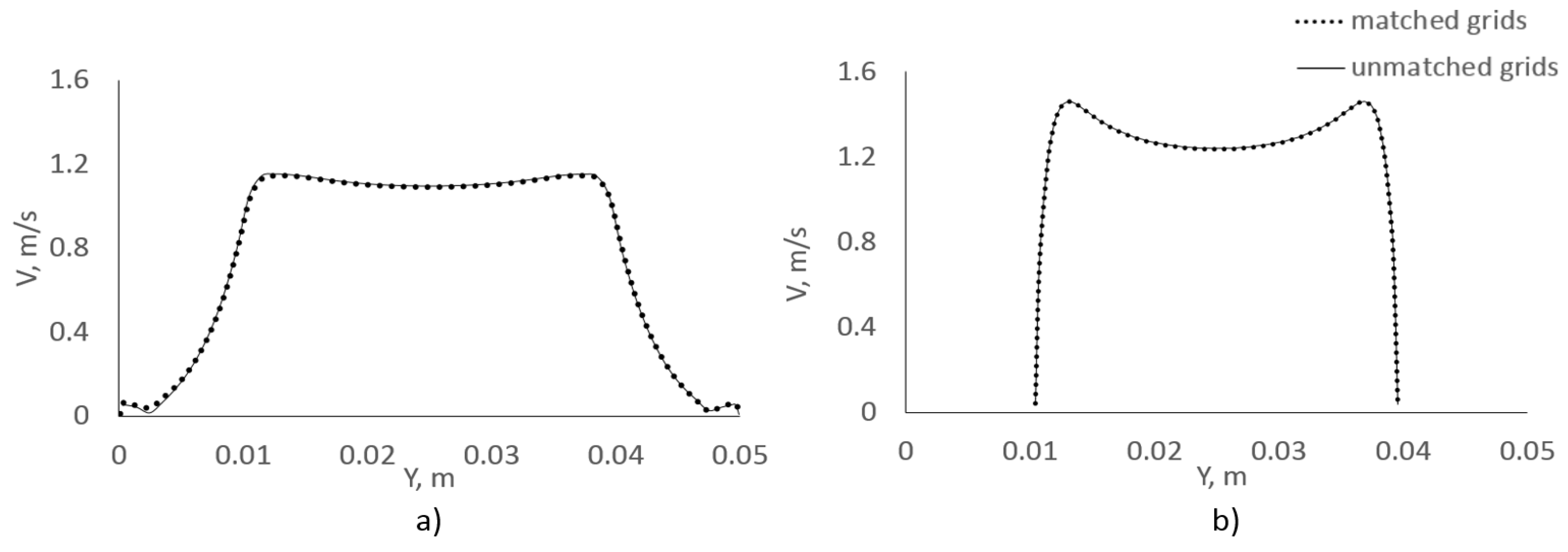
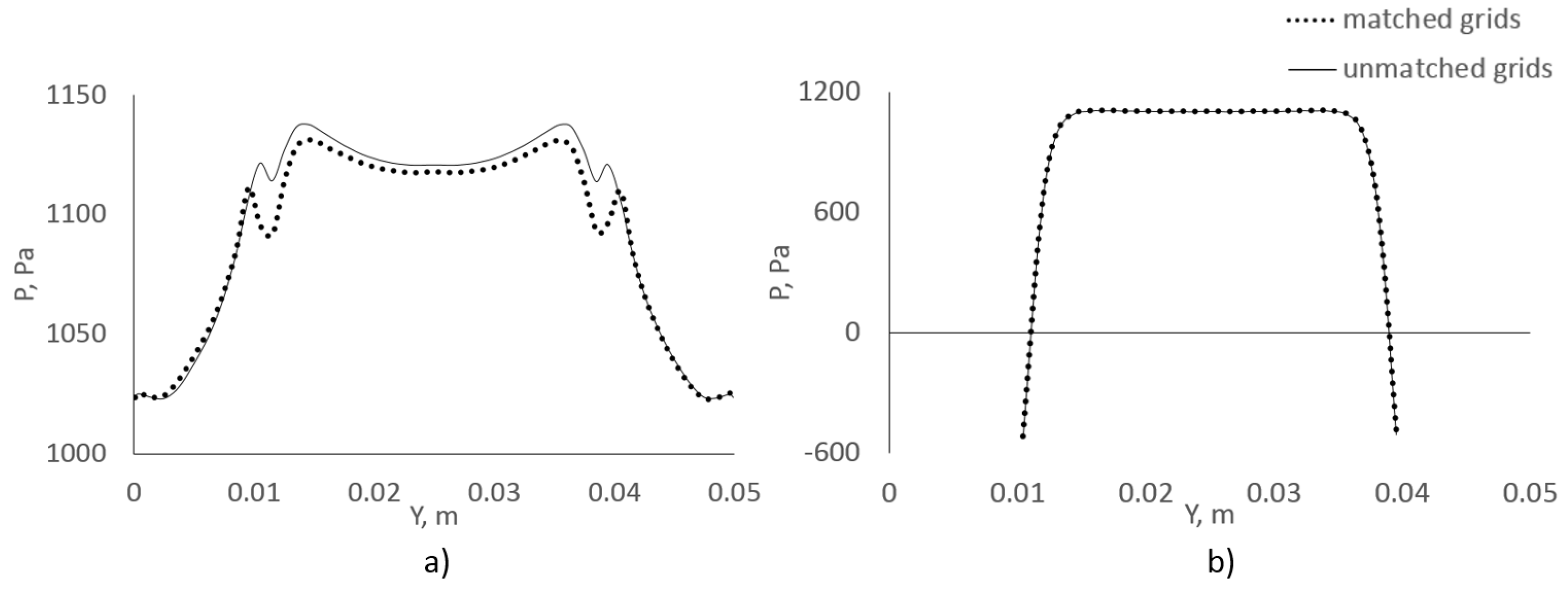
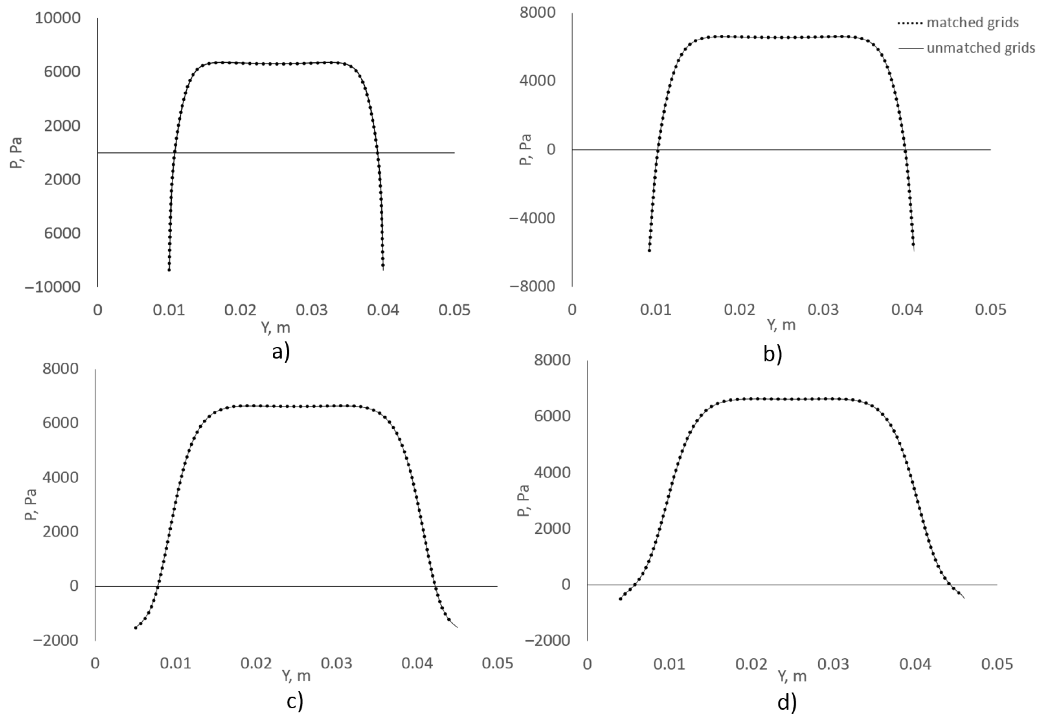
To analyze the results, we compared the profiles of the velocity module (V) and pressure (P) along the horizontal line passing through the middle of the computational model (Figure 11), and the profiles of velocity and pressure at the control sections (Figure 12 and Figure 13).
The resulting profiles of velocity and pressure in the longitudinal and transverse sections demonstrated the close agreement between the results calculated by the matched and unmatched grid models. The convergence graphs indicate that the presence of the unmatched interface has a minor effect on the iteration convergence rate.

3.2. Turbulent Incompressible Fluid Flow in a Circular Diffuser

Let us consider how the method behaves in the numerical simulations of a turbulent flow in a circular pipe with a conical diffuser [24]. The geometry of the computational model and the locations of control sections are shown in Figure 14. To test the method, the calculations were run on a matched and unmatched grid model.
The unmatched grid model consisted of three unmatched areas (upstream pipe fragment, diffuser, and downstream pipe fragment). Grids in each of the areas were generated independently. A grid fragment in the diffuser area is shown in Figure 14. The matched grid model was constructed by an original mesh transformation in the LOGOS pre- and postprocessor to transform the unmatched interfaces into matched ones.
The governing parameters in the computational models included fluid density equal to 772.9 kg/m3 and a dynamic viscosity equal to 0.002682 kg/(m∙s). Under set parameters, the flow Reynolds number was 49989. Turbulent mixing was modeled by the SST turbulence model [26] with a 0.05 percent turbulence intensity and a 0.001 m mixing length. The convective members in the calculations were approximated by the first-order upwind scheme UD [18].
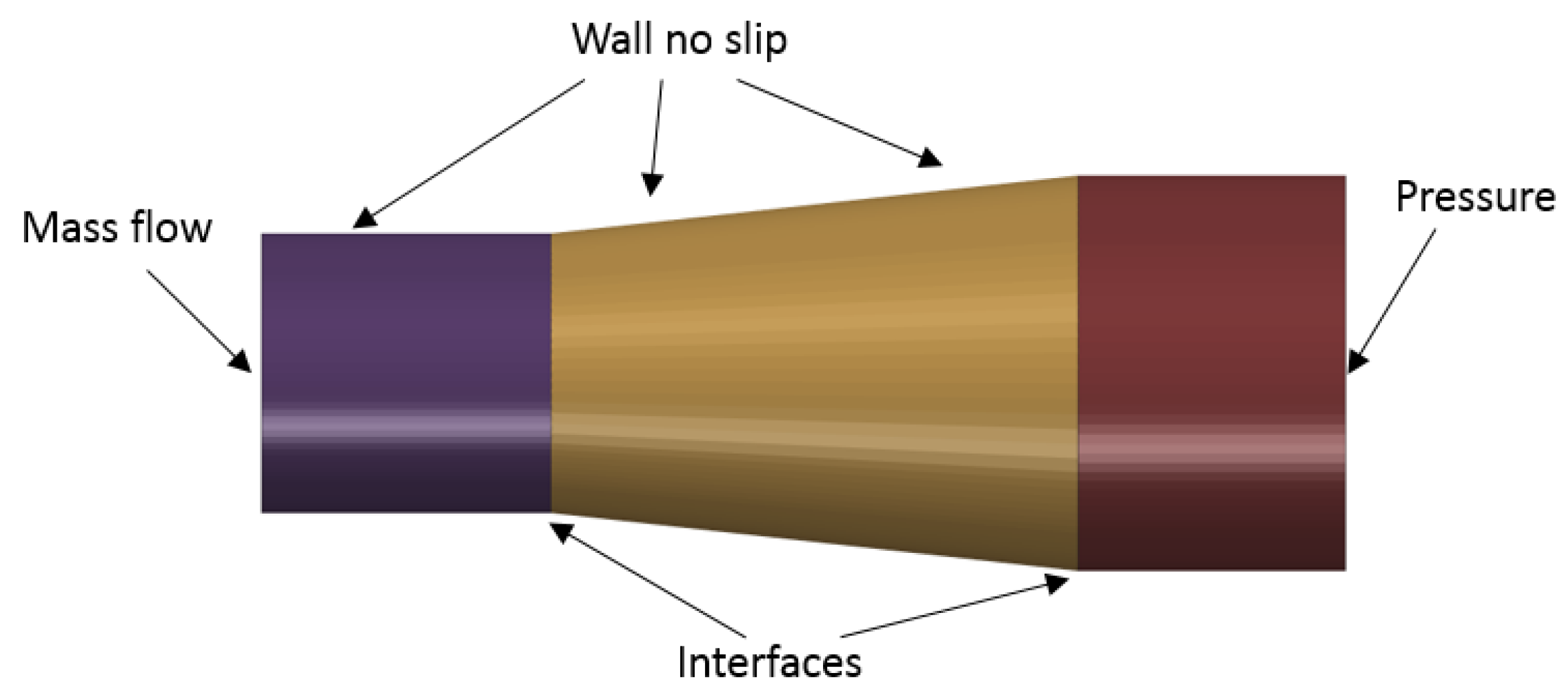
Figure 15 shows the boundary conditions of the computational models. The outer boundaries were impermeable no-slip rigid walls. The inlet velocity was constant and controlled by a constant flow rate of Q = 3.159662 kg/s. To match the solution in the unmatched model, we used the interfaces implemented in LOGOS in accordance with the method described above.
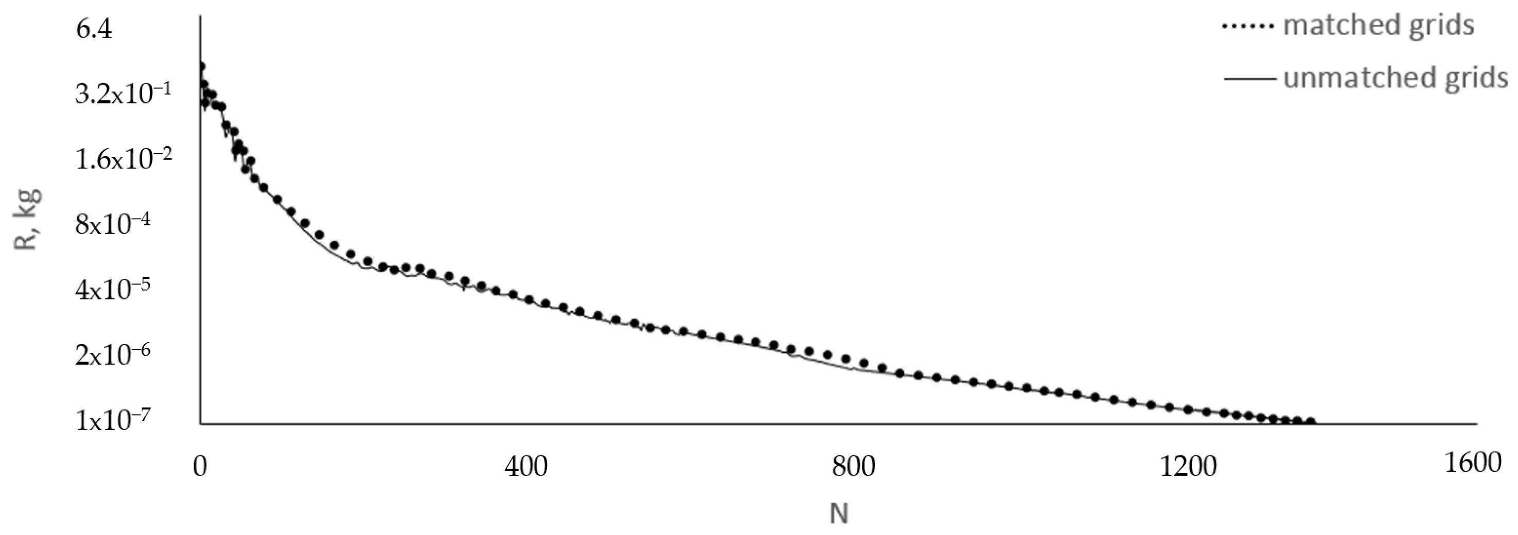
The calculations were performed by LOGOS in a steady setup on 80 parallel processors up to a convergence in mass in the order of 10−6 kg. The iteration convergence graph is shown in Figure 16.
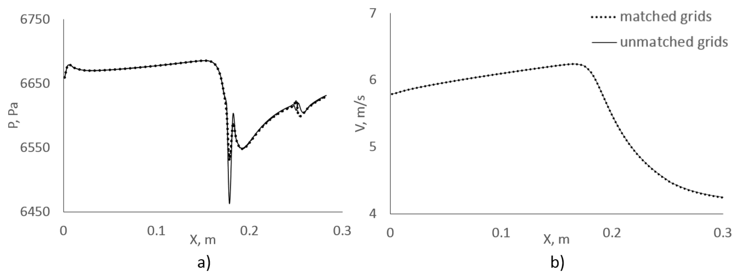
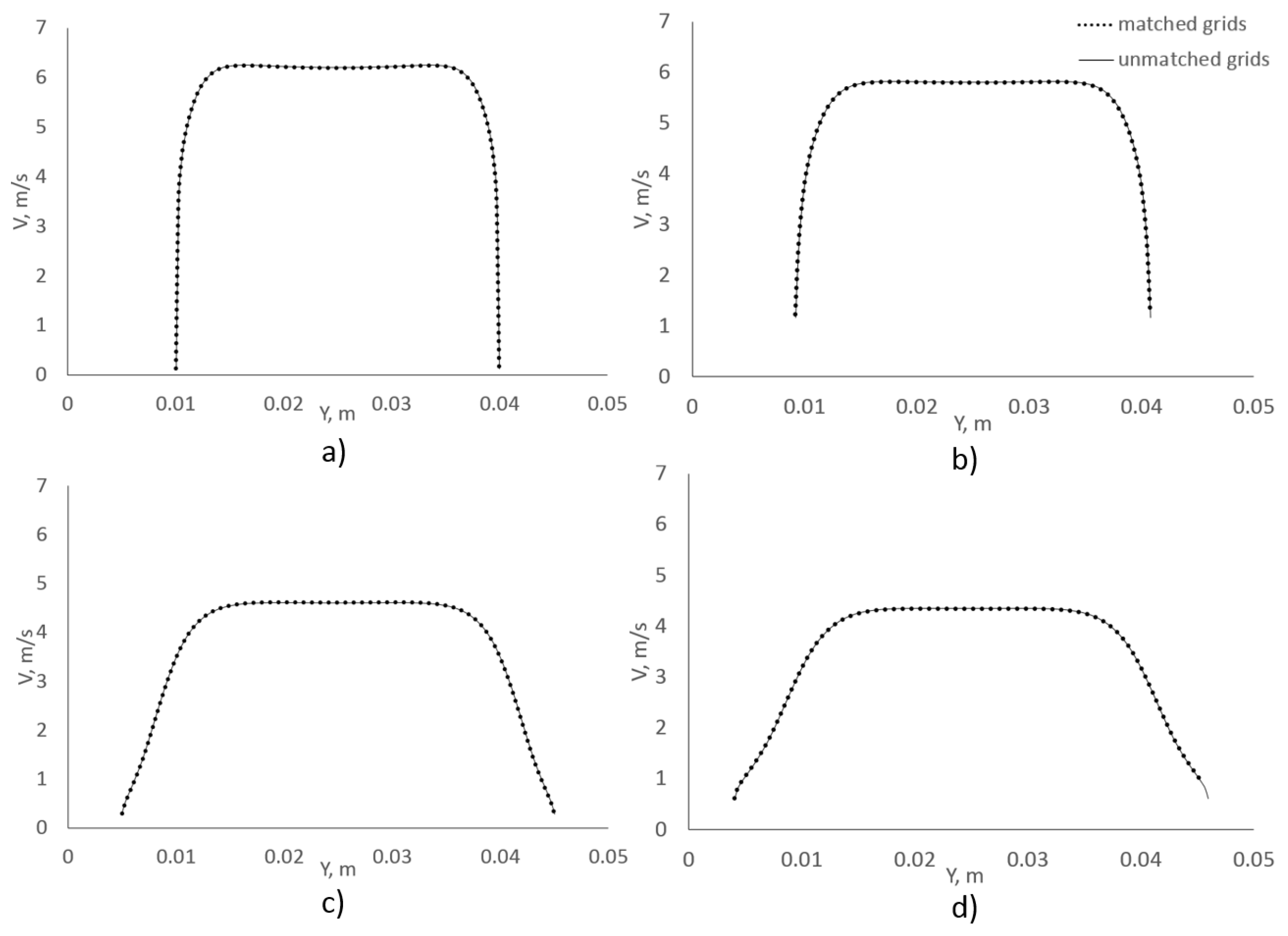
To analyze the results, we compared the profiles of the velocity module and pressure along the horizontal line passing through the middle of the computational model (Figure 17), and the profiles of velocity and pressure at the control sections (Figure 18 and Figure 19).
The resulting profiles of velocity and pressure in the longitudinal and transverse sections demonstrated a close agreement between the results calculated by the matched and the unmatched grid models. The convergence graphs indicate that the presence of the unmatched interface has a minor effect on the iteration convergence rate.

4. Conclusions

In the paper, we described a numerical method, which considers specific aspects of solving the Navier–Stokes equations in viscous incompressible flow simulations in the vicinity of interfaces between unmatched unstructured grid fragments. The method combines adjacent unmatched fragments of an unstructured grid into a single domain by means of virtual interfaces considering the connections between adjacent cells through virtual faces. The algorithm of this method was implemented in the software package LOGOS within its CFD solver, which was used to run test calculations. Results of the test calculations by this method on grid models with matched and unmatched interfaces were presented. The presence of the unmatched interfaces was shown to have no significant effect on the flow pattern and solution convergence rate.

Author Contributions

Conceptualization, A.K. (Andrey Kozelkov) and A.K. (Andrey Kurkin); data curation, A.K. (Aleksey Korotkov), S.L. and E.L.; formal analysis, A.K. (Andrey Kozelkov) and A.K. (Aleksey Korotkov); investigation, A.K. (Andrey Kozelkov), A.K. (Andrey Kurkin), A.K. (Aleksey Korotkov), S.L. and E.L.; methodology, A.K. (Andrey Kozelkov) and A.K. (Andrey Kurkin); software, A.K. (Aleksey Korotkov), S.L. and E.L.; supervision, A.K. (Andrey Kurkin); validation, A.K. (Aleksey Korotkov), S.L. and E.L.; visualization, A.K. (Aleksey Korotkov), S.L. and E.L.; writing—original draft, A.K. (Andrey Kozelkov) and A.K. (Andrey Kurkin); writing—review and editing, A.K. (Andrey Kozelkov) and A.K. (Andrey Kurkin). All authors have read and agreed to the published version of the manuscript.

Funding

This research was funded by the Ministry of Science and Higher Education of the Russian Federation (project No. FSWE-2021-0009 and agreement No. 075-15-2020-924 (Program for Creation and Development of World-Class Scientific Center “Supersonic” in 2020-2022)) and the Council for Grants of the President of the Russian Federation for State Support for Leading Scientific Schools of the Russian Federation (Grant No. NSH-70.2022.1.5).

Conflicts of Interest

The authors declare no conflict of interest.

References

  1. Efremov, V.; Kozelkov, A.; Dmitriev, S.; Kurkin, A.; Kurulin, V.; Utkin, D. Technology of 3D Simulation of High-Speed Damping Processes in the Hydraulic Brake Device. In Modeling and Simulation in Engineering; Volkov, K., Ed.; IntechOpen: London, UK, 2018. [Google Scholar]
  2. Kozelkov, A.S.; Pogosyan, M.A.; Strelets, D.Y.; Tarasova, N.V. Application of mathematical modeling to solve the emergency water landing task in the interests of passenger aircraft certification. Aerosp. Syst. 2021, 4, 75–89. [Google Scholar] [CrossRef]
  3. Struchkov, A.V.; Kozelkov, A.S.; Volkov, K.; Kurkin, A.A.; Zhuchkov, R.N.; Sarazov, A.V. Numerical simulation of aerodynamic problems based on adaptive mesh refinement method. Acta Astronaut. 2020, 172, 7–15. [Google Scholar] [CrossRef]
  4. Spalart, P.; Venkatakrishnan, V. On the role and challenges of CFD in the aerospace industry. Aeronaut. J. 2016, 120, 209–232. [Google Scholar] [CrossRef] [Green Version]
  5. Iranzo, A. CFD Applications in Energy Engineering Research and Simulation: An Introduction to Published Reviews. Processes 2019, 7, 883. [Google Scholar] [CrossRef]
  6. Hamisi, A.M.; Yusufu, A.C.; Thomas, T.K. A Review on Computational Fluid Dynamics Applications in the Design and Optimization of Crossflow Hydro Turbines. J. Renew. Energy 2021, 2021, 5570848. [Google Scholar]
  7. Berger, M. On conservation at grid interfaces. SIAM J. Numer. Anal. 1987, 24, 967–984. [Google Scholar] [CrossRef]
  8. Bjerklund, E. A Modification of the Movingconetopofvmesh Library; Chalmers: Gothenburg, Sweden, 2009. [Google Scholar]
  9. Jasak, H.; Tukovic, Z. Automatic mesh motion for the unstructured finite volume method. Trans. FAMENA 2006, 30, 1–20. [Google Scholar]
  10. Piscaglia, F.; Montorfano, A.; Onorati, A. Development of Fully-Automatic Parallel Algorithms for Mesh Handling in the 435 OpenFOAM®-2.2.x Technology; International Multidimensional Engine Modeling User’s Group: Detroit, MI, USA, 2013. [Google Scholar]
  11. Qin, N.; Carnie, G.; LeMoigne, A.; Liu, X.; Shahpar, S. Buffer layer method for linking two non-matching multi-block structured grids. In Proceedings of the 47th AIAA Aerospace Sciences Meeting Including the New Horizons Forum and Aerospace Exposition, Orlando, FL, USA, 5–8 January 2009. [Google Scholar]
  12. Wang, Y.; Qin, N.; Carnie, G.; Shahpar, S. Zipper layer method for linking two dissimilar structured meshes. J. Comput. Phys. 2013, 255, 130–148. [Google Scholar] [CrossRef]
  13. Zhang, Y.; Chen, H.; Fu, S. Improvement to patched grid technique with high-order conservative remapping method. J. Aircr. 2011, 48, 884–893. [Google Scholar] [CrossRef]
  14. Beaudoin, M.; Jasak, H. Development of Generalized Grid Interface for Turbomachinery simulation with OpenFOAM. In Proceedings of the Open Source CFD International Conference, Berlin, Germany, 4–5 December 2008. [Google Scholar]
  15. Beaudoin, M.; Nilsson, H.; Page, M.; Magnan, R.; Jasak, H. Evaluation of an improved mixing plane interface for OpenFOAM. In IOP Conference Series: Earth and Environmental Science; IOP Publishing: Bristol, UK, 2014; Volume 22, p. 022004. [Google Scholar]
  16. Kozelkov, A.S.; Kurulin, V.V.; Lashkin, S.V.; Shagaliev, R.M.; Yalozo, A.V. Investigation of Supercomputer Capabilities for the Scalable Numerical Simulation of Computational Fluid Dynamics Problems in Industrial Applications. Comput. Math. Math. Phys. 2016, 56, 1506–1516. [Google Scholar] [CrossRef]
  17. Lashkin, S.V.; Kozelkov, A.S.; Yalozo, A.V.; Gerasimov, V.Y.; Zelensky, D.K. Efficiency Analysis of the Parallel Implementation of the SIMPLE Algorithm on Multiprocessor Computers. J. Appl. Mech. Tech. Phys. 2017, 58, 1242–1259. [Google Scholar] [CrossRef]
  18. Ferziger, J.H.; Peric, M. Computational Method for Fluid Dynamics; Springer: New York, NY, USA, 2002. [Google Scholar]
  19. Landau, L.D.; Lifshitz, E.M. Hydrodynamics; Pergamon Press: Oxford, UK, 1987. [Google Scholar]
  20. Mozer, D.; Kim, J.; Mansour, N.N. DNS of Turbulent Channel Flow. Phys. Fluids 1999, 11, 943–945. [Google Scholar]
  21. Jasak, H. Error Analysis and Estimation for the Finite Volume Method with Applications to Fluid Flow; Department of Mechanical Engineering, Imperial College of Science: London, UK, 1996. [Google Scholar]
  22. Saad, Y. Iterative Methods for Sparse Linear Systems; SIAM: Minneapolis, MN, USA, 2003. [Google Scholar]
  23. Chentsov, O.V.; Skvortsov, A.V. Overview of polygon overlay construction algorithms. Bull. Tomsk State Univ. 2003, 280, 338–345. [Google Scholar]
  24. Idel’chik, I.E. Handbook of Hydraulic Resistance; Mashinostroenie: Moscow, Russia, 1992. [Google Scholar]
  25. Tyatyushkina, E.S.; Kozelkov, A.S.; Kurkin, A.A.; Pelinovsky, E.N.; Kurulin, V.V.; Plygunova, K.S.; Utkin, D.A. Verification of the LOGOS Software Package for Tsunami Simulations. Geosciences 2020, 10, 385. [Google Scholar] [CrossRef]
  26. Menter, F.R.; Garbaruk, A.V.; Egorov, Y. Explicit algebraic Reynolds stress models for anisotropic wall-bounded flows. In Proceedings of the 3rd European Conference for Aero-Space Sciences (EUCASS), Versailles, France, 6–9 July 2009. [Google Scholar]
Figure 1. Schematic example of a grid with matched inner interfaces.
Fluids 07 00346 g001
Figure 2. Schematic example of a grid with a matched interface.
Fluids 07 00346 g002
Figure 3. Creation of virtual faces.
Fluids 07 00346 g003
Figure 4. Creation of the virtual faces on the unmatched interface.
Fluids 07 00346 g004
Figure 5. Schematic example of a grid with unmatched inner interfaces.
Fluids 07 00346 g005
Figure 6. Schematic example of a grid with an unmatched interface.
Fluids 07 00346 g006
Figure 7. Model geometry and location of control sections. Dimensions are given in mm.
Fluids 07 00346 g007
Figure 8. Unmatched grid fragments in the longitudinal and lateral sections.
Fluids 07 00346 g008
Figure 9. Boundary conditions: (a) matched grid model, (b) unmatched grid model.
Fluids 07 00346 g009
Figure 10. Convergence graph (R is the mass discrepancy, N is the step number).
Fluids 07 00346 g010
Figure 11. Profile along the channel: (a) velocity module, (b) pressure.
Fluids 07 00346 g011
Figure 12. Profile of velocity at the control sections: (a) section A1, (b) section A2.
Fluids 07 00346 g012
Figure 13. Profile of pressure at the control sections: (a) section A1, (b) section A2.
Fluids 07 00346 g013
Figure 14. Computational model geometry (dimensions are given in mm) and grid fragment in the diffuser area.
Fluids 07 00346 g014
Figure 15. Boundary conditions in the matched grid model.
Fluids 07 00346 g015
Figure 16. Convergence graph (R is the mass discrepancy, N is the step number).
Fluids 07 00346 g016
Figure 17. Profile of velocity module (a) and pressure (b) along the channel.
Fluids 07 00346 g017
Figure 18. Profile of velocity at the control sections: (a) section A1, (b) section A2, (c) section A3, (d) section A4.
Fluids 07 00346 g018
Figure 19. Profile of pressure at the control sections: (a) section A1, (b) section A2, (c) section A3, (d) section A4.
Fluids 07 00346 g019
Publisher’s Note: MDPI stays neutral with regard to jurisdictional claims in published maps and institutional affiliations.