Abstract
The possibility of extracting large amounts of electrical power from turbofan engines is becoming increasingly desirable from an aircraft perspective. The power consumption of a future fighter aircraft is expected to be much higher than today’s fighter aircraft. Previous work in this area has concentrated on the study of power extraction for high bypass ratio engines. This motivates a thorough investigation of the potential and limitations with regards to performance of a low bypass ratio mixed flow turbofan engine. A low bypass ratio mixed flow turbofan engine was modeled, and key parts of a fighter mission were simulated. The investigation shows how power extraction from the high-pressure turbine affects performance of a military engine in different parts of a mission within the flight envelope. An important conclusion from the analysis is that large amounts of power can be extracted from the turbofan engine at high power settings without causing too much penalty on thrust and specific fuel consumption, if specific operating conditions are fulfilled. If the engine is operating (i) at, or near its maximum overall pressure ratio but (ii) further away from its maximum turbine inlet temperature limit, the detrimental effect of power extraction on engine thrust and thrust specific fuel consumption will be limited. On the other hand, if the engine is already operating at its maximum turbine inlet temperature, power extraction from the high-pressure shaft will result in a considerable thrust reduction. The results presented will support the analysis and interpretation of fighter mission optimization and cycle design for future fighter engines aimed for large power extraction. The results are also important with regards to aircraft design, or more specifically, in deciding on the best energy source for power consumers of the aircraft.
1. Introduction
Air vehicle design is moving towards increased electrification [1]. This holds for the military sector as well [2]. An increased amount of electrical equipment, with higher power demands, is contributing to this development. Hydraulic systems and components are being replaced by electrical systems and components [3]. Increasing aircraft power consumption will not only put new requirements on the aircraft engine with regards to engine performance, stability, and operability, but increased power will create excessive heat, which must be taken care of by the aircraft [4]. Efficient energy management of the aircraft will be crucial to handle this excessive heat [2].
In turbofan engines, electrical power is extracted by a generator connected to one of the rotating shafts, usually via an accessory gearbox [5], but future engines might have generators directly mounted to the shaft [6]. Typical power consumers are pumps, aircraft hydraulic systems, pneumatic systems and electrical systems such as control systems [7,8]. The extracted power is a small fraction of the total useful power generated by the engine and the main power output is in the form of high velocity jets and thrust generation.
Civil aircraft typically use high bypass ratio turbofan engines with separate exhausts, as they increase propulsive efficiency [7]. The search for improved efficiency to achieve reduced fuel consumption and emissions is one of the main drivers for performance analysis of high bypass ratio turbofan engines. Different cycle parameters’ impact on efficiency and loss of work availability is presented in [9,10]. The increased fuel consumption due to power and bleed extraction is investigated in [11,12,13].
In recent years, concepts of hybrid electric propulsion (HEP) have been investigated in search of reductions in fuel consumption and emissions. HEP systems often require large power extraction from the gas turbine. The EU Horizon 2020 project CENTRELINE investigated one concept of HEP, where an aft mounted fan, intended for boundary layer ingestion (BLI), is powered by power extraction from the turbofan engine [14]. Another concept of hybrid propulsion, called Parallel Hybrid Electric Turbofan, was used for evaluation of a proposed concept to maintain stall margin with the use of electrical machines called Turbine Electrified Energy Management [15]. Methods to extract from and insert power to an aircraft engine are studied in [16] as well, but in this case, as a means for thrust increase. The evaluated concept was the storage of energy in a power insertion device, such as an external battery, which allows a temporary increase in thrust by re-introducing power into the low- or high-pressure shaft. Similar investigations are performed in [17,18], but in this case electric motors are used exclusively to assist at certain occasions with high thrust requirements, such as take-off and climb, allowing a relaxation of the engine thrust requirement. If the thrust constraints can be relaxed, the engine can be designed to maximize cruise performance.
Military engines combine the need for high efficiency with a need for high specific thrust [19]. Low bypass ratio mixed flow turbofan engines used for military applications differ considerably compared to high bypass ratio turbofan engines with respect to engine performance, control constraints, the more complex mission definition and the use of afterburner. Recent research on low bypass ratio mixed flow turbofan engines has focused on areas such as cycle parameter optimization [20,21,22] and use of bypass air for cooling purposes [23]. It is remarkable that despite the continuously growing power demand from advanced radars, electrical actuation and mission systems [2], up until now very little work has been devoted to the field of power extraction and its relation to the performance of the propulsion system. This area is the main focus of the work presented herein.
In recent years, a lot of research has focused on Variable Cycle Engines (VCEs) [24] and, particularly, the Adaptive Cycle Engine (ACE) concept [25] that is currently being developed for the next generation fighter aircraft. The ACE and VCE concepts can be adapted to achieve high specific thrust at operating conditions when high thrust is required, without sacrificing fuel consumption at cruise. A study on transient shaft power extraction using a VCE is presented in [26]. In [25], the ACE concept is evaluated as a means of providing high-level power extraction from both shafts for a Directed Energy Weapon (DEW). The studied ACE consists of a very sophisticated three-stage fan with several variable areas called Convertible Fan Stage (CFS), which divides the flow into three different bypass flows. The concept was used to simulate power extraction up to 5 MW. It was concluded that the ACE concept could deliver high amounts of power during combat as well as re-charging the DEW during cruise conditions. The ACE concept can be sufficiently adapted for different operating conditions. Conventional turbofan engines do not offer such a high degree of flexibility, and the power extraction capability of the conventional turbofan engine is therefore not as high.
The focus of this article is to explore the low bypass ratio mixed flow turbofan engine’s potential and limitations for power extraction in different parts of a fighter aircraft mission. The analysis is performed from an engine performance perspective. In the literature review undertaken, no article with this topic was found. This clearly illustrates the degree of novelty in this article, that is, performance analysis of conventional low bypass ratio mixed flow turbofan engines with large power extraction. It will be shown that power can be extracted from the HPT at occasions with high overall pressure ratios without sacrificing too much on SFC or thrust, provided that a sufficient T4 increase is possible.
The main body of the article is divided into three parts. First, a summary of materials and methods is provided in Section 2, outlining the aircraft mission and the modeling and methods used. The research results are provided in Section 3. This part is divided into two subsections; the first part handles single design point results. The second part covers a parametric mission analysis study covering a range of overall design pressure ratios (OPR). The applied methodology is described in Section 2. Once the potential and limitations of power extraction with regards to engine performance have been identified, it opens up a broader discussion about implications for fighter aircraft missions, use of power storage devices and appropriate engine cycle design for different fighter missions with power extraction requirements. This discussion is initiated in Section 4.
2. Materials and Methods
The development of tools for turbofan engine performance analysis is a common topic of performed research work within the area [27,28,29,30,31]. If test data is publicly available, which is rarely the case for fighter aircraft engines, a method for parameter matching is proposed in [32]. In recent years, the use of generic algorithms for diagnostics and performance estimations has become popular. One example is provided in [33]. The use of machine learning and neural networks to create more accurate estimations and models is becoming more common, both for propulsion purposes [34] and for other fields of power generation [35].
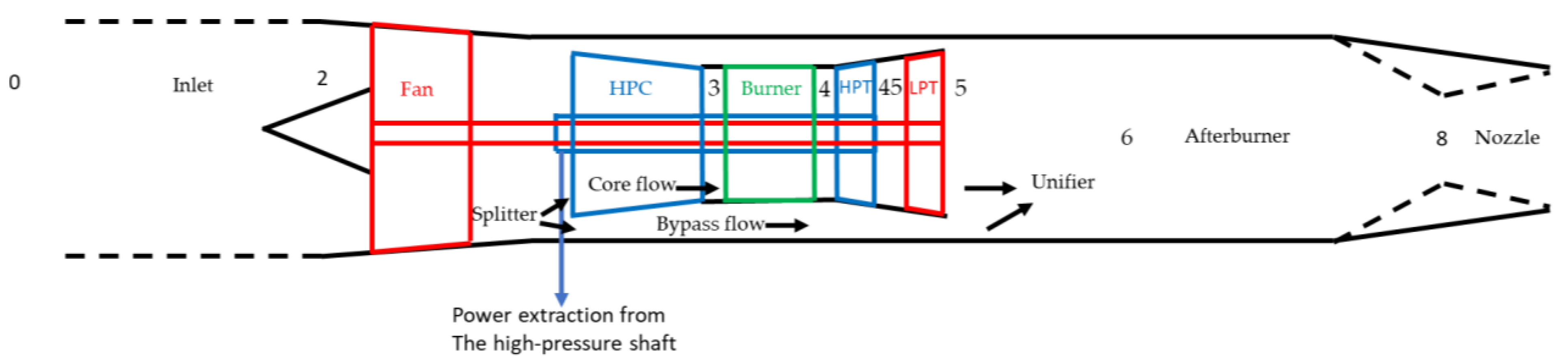
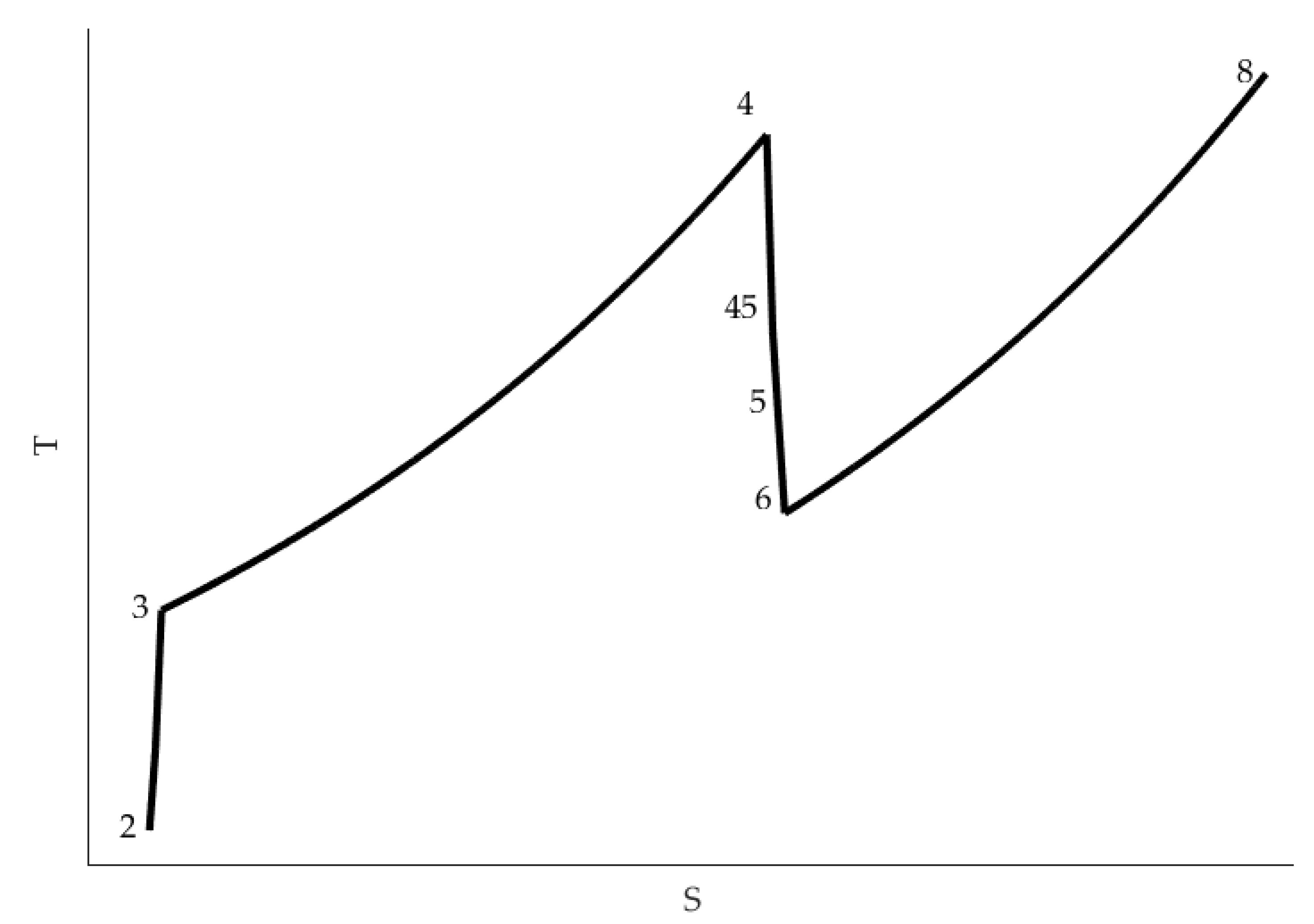
In this work, a low bypass ratio mixed flow turbofan engine has been modeled in the tool GESTPAN (GEneral Stationary and Transient Propulsion ANalysis) [36]. An overview of the engine is given in Figure 1. It follows the standardized station numbering according to the Society of Automotive Engineers (SAE) Aerospace Recommended Practice (ARP) 755 as described in [7]. A schematic T-S diagram is provided in Figure 2 illustrating an operating point where the afterburner is used. The numbers in Figure 2 show the different station numbers as illustrated in Figure 1.
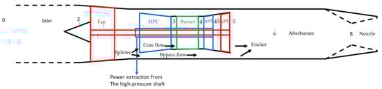
Figure 1.
Overview of the modeled engine.

Figure 2.
Schematic T-S diagram. Use of afterburner illustrated.
The engine model consists of the following components:
- Inlet
- Fan (LPC)
- Splitter
- High pressure compressor (HPC)
- Burner
- High-pressure turbine (HPT)
- Low-pressure turbine (LPT)
- Unifier (Mixer)
- Afterburner
- Nozzle
The fan (LPC) pressurizes incoming air. The air flow is then split up; one part, the core flow, is directed to the HPC and the remaining air flow is bypassed. The core flow is further compressed in the HPC and then led to the burner for combustion. After combustion, the core flow is expanded, first in the HPT and then in the LPT. Power is extracted from the HPT and LPT. In this study, the HPT provides shaft power both to the HPC and to a generator for electric power generation. The LPT provides shaft power to the fan. Turbofan engines, designed for fighter aircraft, use mixed exhausts [7]. The core flow and bypass flow are mixed in the unifier before entering the afterburner. The afterburner offers an opportunity to increase engine thrust at flight cases where high engine thrust is required; the use of afterburner is referred to as “augmented power” or “augmented” in the text. The mixed flow is finally accelerated in the nozzle. An engine process model diagram is shown in Figure 3.

Figure 3.
Engine process model diagram.
The system of equations solved arise from conservation laws, frequently referred to as compatibility equations [37]. These equations ensure:
- Compatibility of work
- Compatibility of flow
- Compatibility of rotational speed
Detailed implementations of the modelled components are outlined in Appendix A in [36]. Graph theory is used in GESTPAN to automatically assemble a set of equations of minimum size, generally represented by a system of non-linear differential algebraic equations:
x’ = f(x,z)
0 = g(x,z)
For the mission studies performed in this work, engine dynamics is not considered, thus the x’ vector is a zero vector. The algebraic vector z is comprised of nine iteration variables equating nine residuals arising in the system. The variables are given in Table 1.

Table 1.
Iteration variables and residuals of the GESTPAN calculations.
The equation solver uses a secant method with a Broyden update for the Jacobian [38,39] implemented in [40].
Cycle analysis for defined engine alternatives is carried out without and with power extraction from the high-pressure turbine (HPT) at different off-design points defining the fighter aircraft mission, as presented in Table 2 [41].
Table 2.
Key parts of mission [41]. For the mission phase specification, “augmented” refers to use of afterburner.
The different mission points are calculated as off design points where GESTPAN iterates to achieve the required thrust specified in Table 2, but the iterations are constrained by limitations of the following parameters [42]:
- Overall pressure ratio (OPR)
- Turbine inlet temperature (T4)
The constraints are managed by the engine control residual (see Table 1), which uses the engine thrust requirement unless one of the constraints are active. If both constraints are active, the solver attempts to isolate the most severe constraint. There are, of course, other limitations to the engine operating envelope as discussed in [5,43,44], but they are not evaluated further in this article.
The analysis of the results presented in this work is divided into two separate parts:
- In the first results part, Section 3.1, the thermodynamic cycle is defined by one single design point.
- The second part, Section 3.2, illustrates how a parametric variation of design OPR affects the engine’s ability to handle large power extraction.
The engine cycle data is based on information from the open literature [42,43,45,46,47,48] and has been adapted for the engine to meet the specific constraints provided in Table 2. Considerations regarding the design values are presented in Section 3.1, and a comprehensive compilation of simulation results performed with the single design point is provided in Appendix A.
In the second part, a parametric analysis is performed with 295 design points. All design points have common design parameters based on public sources, but the design OPR ranges from 13 to 40. Within the range, there are groups with one common OPR but with small variations of fan pressure ratio (FPR) and high-pressure compressor pressure ratio (HPCPR). The off-design points, corresponding to the mission points in Table 2, are simulated for each design point.
Power extraction is only evaluated from an engine perspective. Possible limitations of power equipment are not considered here. The impact on fan and high-pressure compressor surge margin is not included in this article, but must be considered during the design of a turbofan engine aimed at large power extractions as the required temperature increase moves the operating point towards surge [7,45,49].
3. Results
The analysis is carried out in two main parts; (i) a single design point evaluation, where details of the different parts of the mission are studied more closely, and (ii) a general approach where design points with different design OPR are evaluated.
3.1. Single Design Point Evaluation
To evaluate the power extraction impact in each defined mission point of Table 2, calculations have initially been carried out with a single design point. The main characteristics of the design point are given in Table 3. The engine controller limits OPR to 32 and turbine inlet temperature to 2260 K, the maximum inlet temperature of the F135 jet engine according to [46]. This is indeed a very high temperature and certainly has its challenges regarding material strength, thermal corrosion, cooling requirements etc. [5,46,50], but the obvious advantages of operating at high temperatures are improved thermal efficiency and increased power output per unit of mass flow of air [45,46]. Power is extracted at the defined off-design points representing the mission points described in Table 2.
Table 3.
Design point characteristic.
Two cases are evaluated:
- Reference case—No power extraction
- Power extraction case—900 kW power extraction from the HPT
Some reflections can be made about the design parameters specified above. With a turbine inlet temperature in the range 1900–2000 K, an OPR in the range of 32–35 is suggested in [43]. If the maximum OPR limit is raised to a higher value, the engine performance at high altitudes/low Mach numbers can be improved, but this will require a higher aerodynamic overspeed margin compared to the design point [51]. An increased aerodynamic overspeed margin will increase both maximum corrected mass flow and maximum pressure ratio relative to the design point. If the corrected mass flow and pressure ratio of the design point is unaltered, a compressor map expansion is required, which in turn requires an increased engine inlet area. However, this inlet area increase will increase the aircraft fuselage cross-sectional area, causing increased aircraft weight [51] and aircraft drag [42]. One might want to sacrifice low speed/high altitude performance of the engine by limiting the maximum allowed corrected mass flow and pressure ratio. This will allow for a smaller cross-sectional area of the inlet. Hence, at low speeds/high altitudes and maximum power, the engine controller will limit OPR to its maximum value [42]. At these occasions, the turbine inlet temperature (T4) will not reach its maximum value and the specific thrust of the engine will not be as high as if it could operate at the maximum temperature [42].
A fan pressure ratio (FPR) of 5.4 is high. High FPR causes increased thrust specific fuel consumption (SFC) at dry operation and higher temperatures at the later stages of the HPC [47]; the HPC must be designed for such high temperatures at the HPC outlet and more cooling flow will be required for turbine blade cooling when the HPC outlet temperature rises; moreover, increased FPR is hard to achieve without adding additional stages. To reduce the weight of the engine, the number of fan stages should be as few as possible; the maximum fan pressure ratio is about five with a three-stage fan according to [52]. However, technology improves and the high efficiency transonic axial flow compressors of today have pressure ratios of about 1.7–1.8 per stage [53]. If the challenges can be overcome, increased FPR will improve the specific thrust [7,20,47], which is very desirable from a military engine perspective as it allows for a reduced cross-sectional area [19,47].
Bypass ratios can be expected in the range 0.3–0.6 for a modern, low bypass ratio mixed flow turbofan engine aimed at fighter aircraft [7,42,43,45]. 900 kW is a high amount of power extraction, especially at higher altitudes and lower flight Mach numbers [45]. In the performance requirements of [42], a total shaft power of 300 kW is specified, for example. A crude comparison with a civil aircraft engine [54] reveals that around 300 kW/50 kN is used. This best compares with the 900 kW extracted at mission point 7 with a net thrust of 12.4 kN.
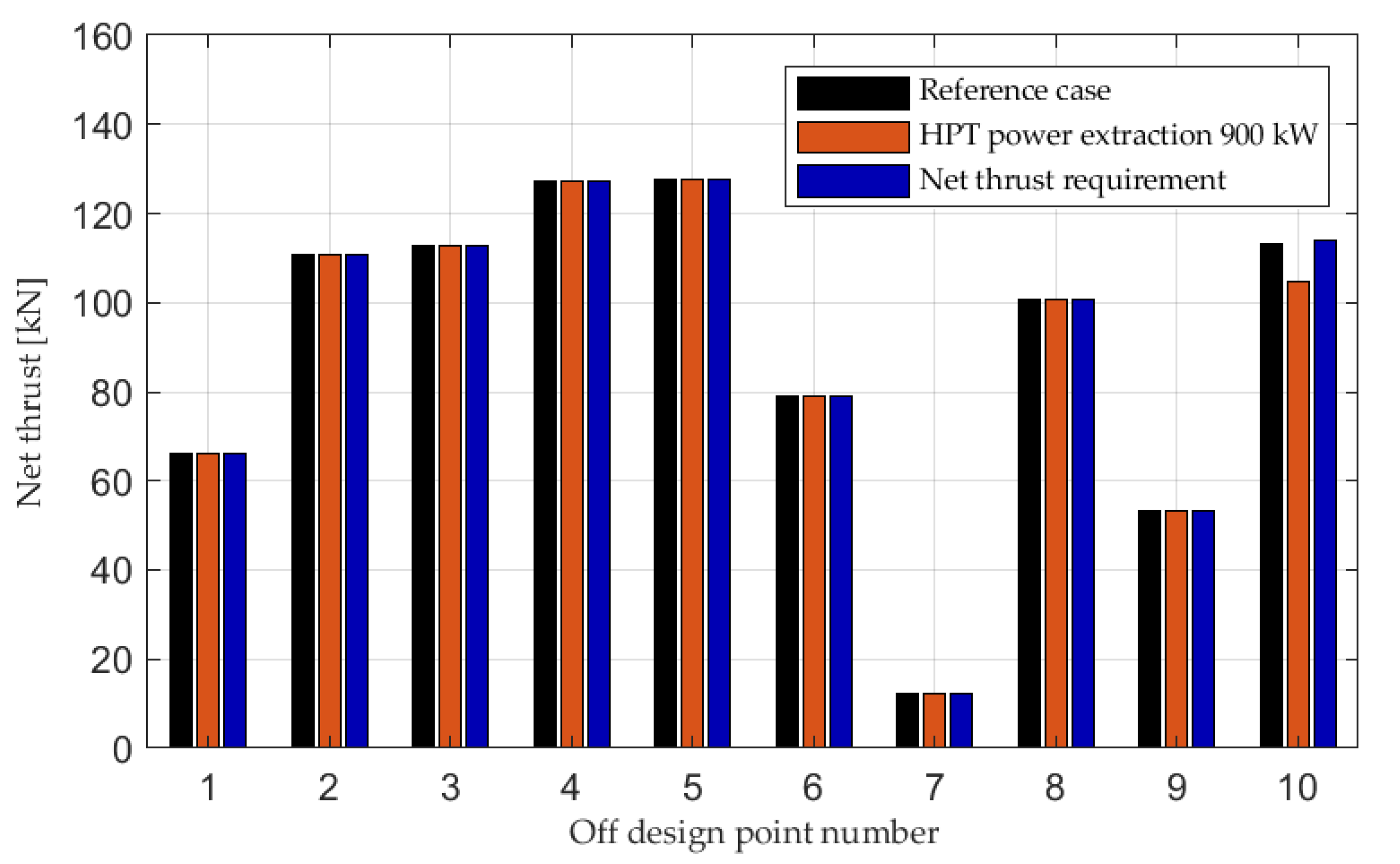
Figure 4 shows the net thrust of the reference case without power extraction, the corresponding net thrust with 900 kW power extraction and the net thrust requirement for all mission points specified in Table 2. An extensive summary of the simulation results is given in Appendix A. The required net thrust is achieved for all parts of the mission except for point number 10, the escape dash. In this case, HPT power extraction causes a considerable net thrust loss. While the reference case with no HPT power extraction almost meets the net thrust requirement of Table 2, the deviation is less than 1%, and the corresponding net thrust deviation with HPT power extraction is 8%.

Figure 4.
Net thrust with and without HPT power extraction.
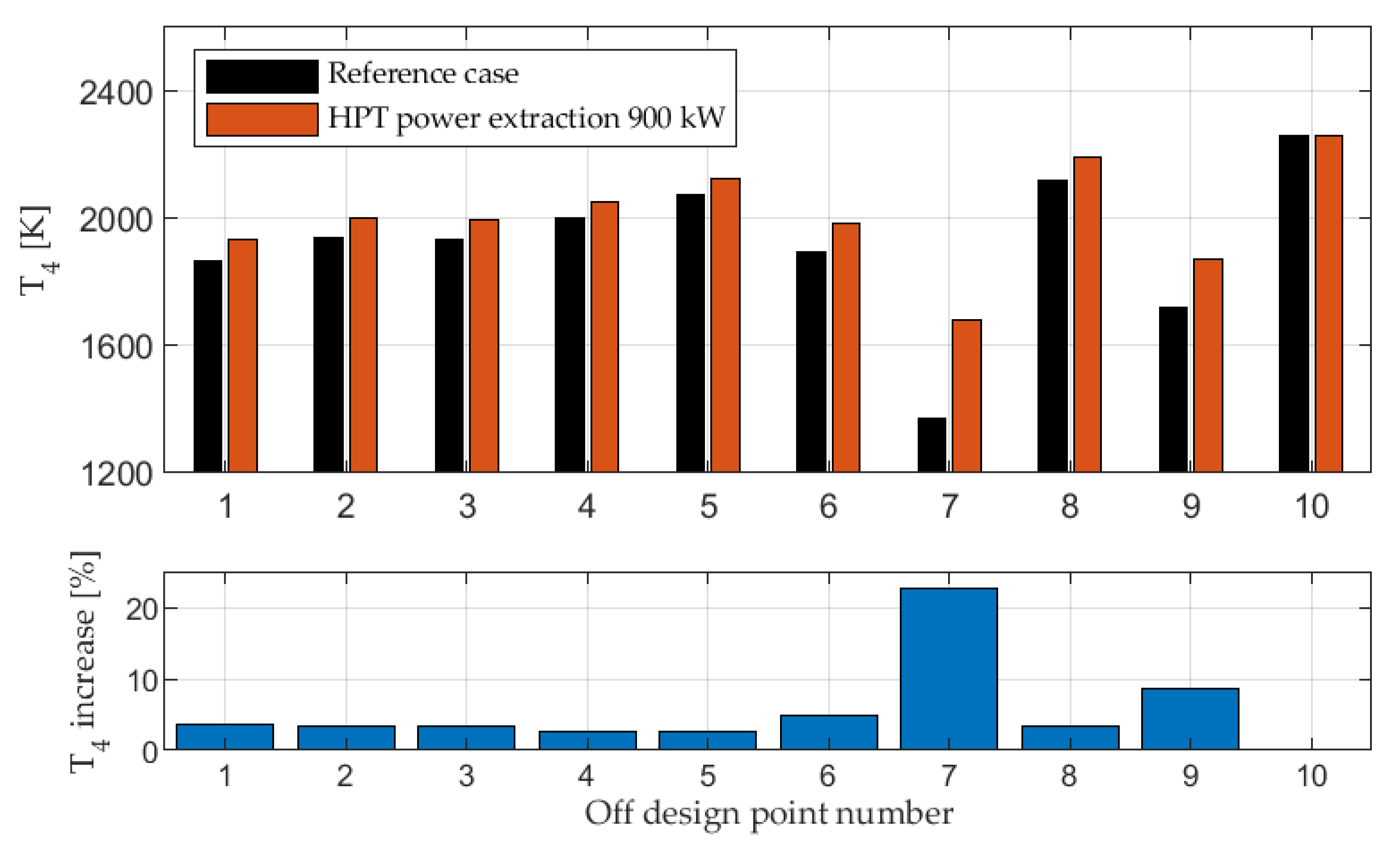
The engine is running at a higher T4 to meet the higher power output required from the HPT as shown in Figure 5. The need for temperature increases to meet the thrust requirements provided in Table 2 is consistent with statements and findings in [7,12,16,25]. In point 10, where the engine is limited by its maximum T4, HPT power extraction has an adverse effect on engine net thrust, causing the net thrust decrease shown in Figure 4.
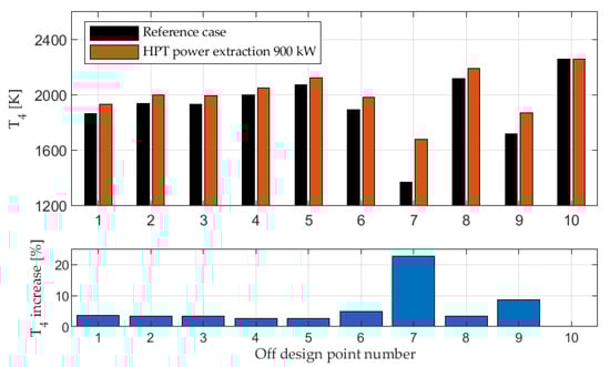
Figure 5.
Turbine inlet temperature, T4, with and without HPT power extraction.
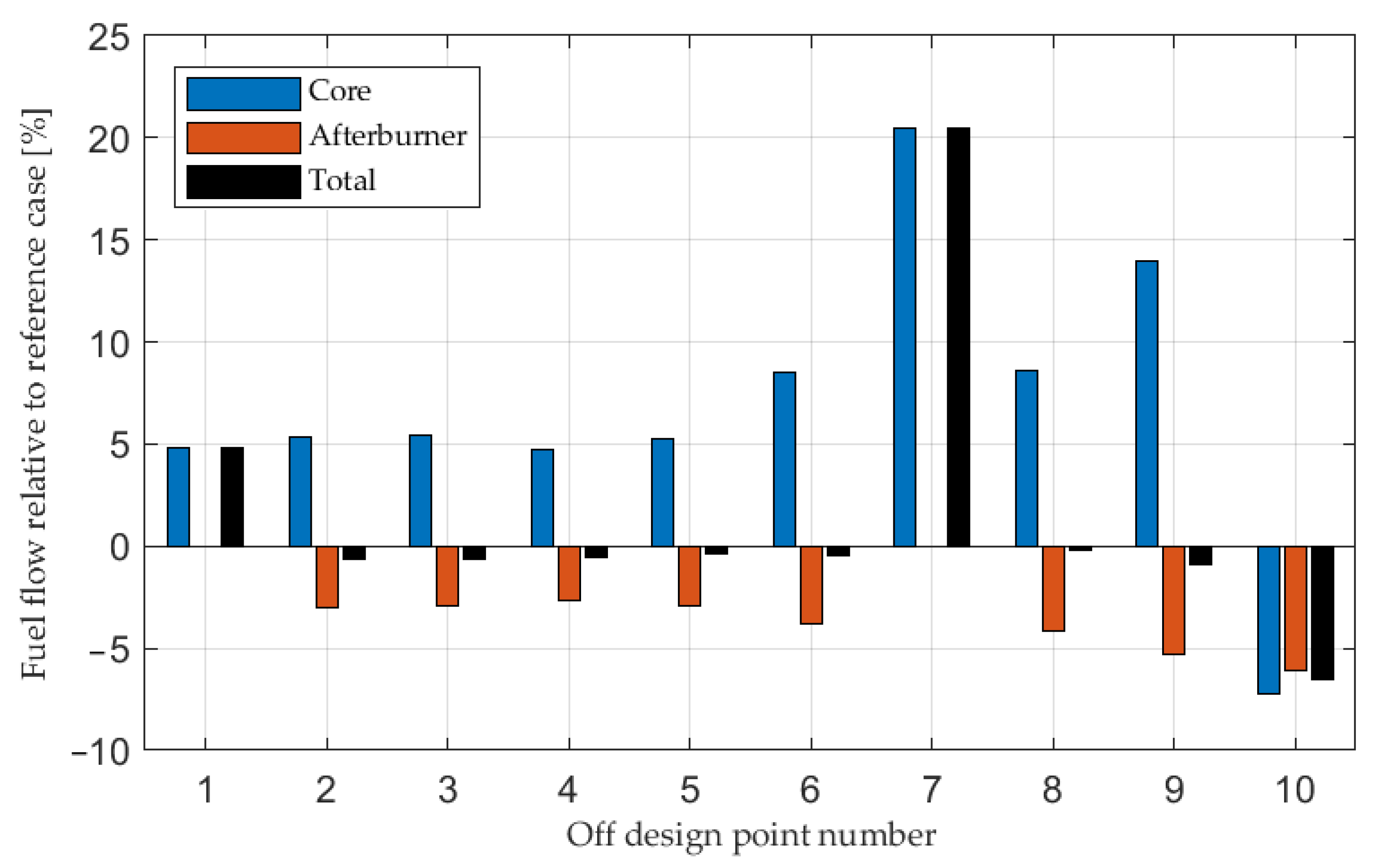
Figure 6 illustrates the relative deviation of SFC for the power extraction case compared to the reference case. The SFC increase at the non-augmented mission points 1 and 7 is in line with previous investigations performed for high bypass ratio turbofan engines and power extraction [11,12,13,16], but it should be noted that SFC is improved for point 2–6 and 8–9 with power extraction compared to the reference case. These are all cases where the engine operates near or at its OPR upper limit. At these cases, the increased core fuel flow is compensated by an afterburner (A/B) fuel flow reduction, shown in Figure 7. From a thermal efficiency perspective, it is always better to add heat at a higher pressure [45]. A schematic T-S diagram, given in Figure 8, is used to explain this further. The numbers in Figure 8 correspond to the station numbers shown in Figure 1. At lower engine power settings, the power extracted from the HPT accounts for a larger share of the total power generated by the engine, and this increases SFC significantly, as shown by point 7 in Figure 6. This complies with earlier investigations performed with power extraction from high bypass ratio turbofan engines [11].
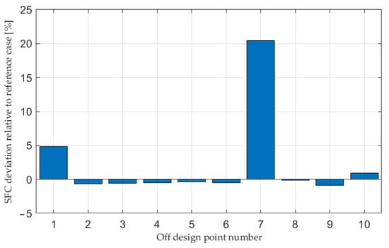
Figure 6.
SFC deviation with HPT power extraction compared to the reference case.

Figure 7.
Core, afterburner and total fuel flow deviation with HPT power extraction compared to the reference case.
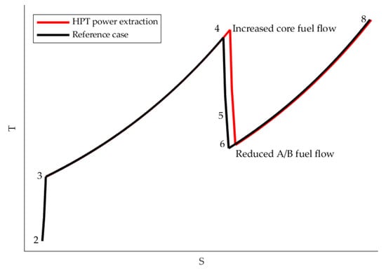
Figure 8.
Schematic T-S diagram to explain how power extraction can improve SFC at afterburner operation when core fuel flow and turbine inlet temperature increase while afterburner fuel flow decreases.
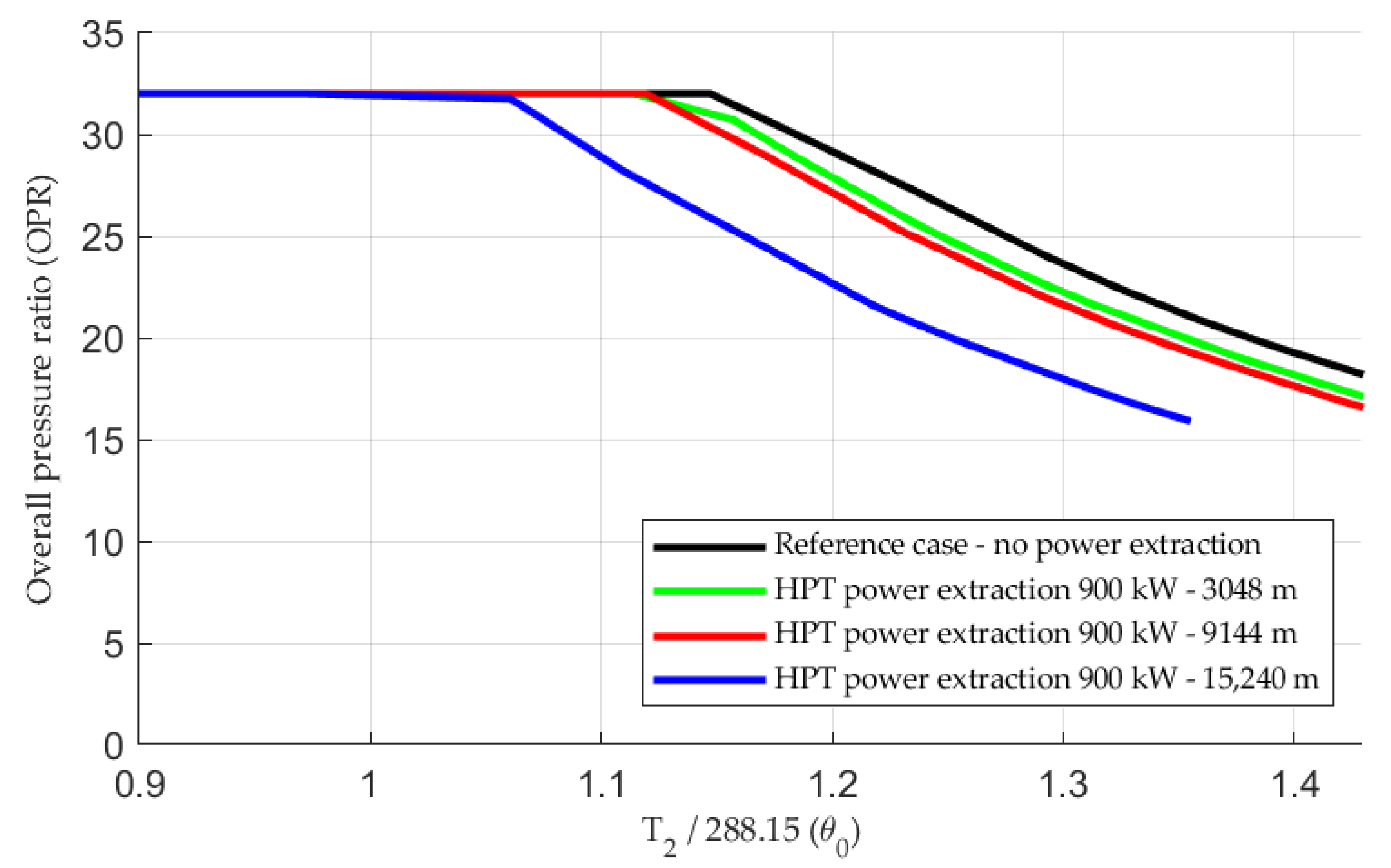
The investigation suggests that HPT power extraction can be accomplished without sacrificing too much on SFC or net thrust, provided that the engine is not running at or near its maximum T4 limitation. Figure 9 shows how the θ0 (T2/288.15) break, described in [42], is pushed to the left at higher altitudes when power is extracted. This is due to the higher temperature drop required to provide the extracted power. Consequently, the adverse effect of HPT power extraction will increase with higher altitude and reduced speed, which is expected since the extracted power becomes relatively larger compared to the total engine power. In fact, a 1 kW power offtake at 18 km altitude and Mach number 0.55 is comparable to 2 kW power extraction at 15 km and Mach number 0.8, or a power offtake of 12 kW at the sea level static case [45].
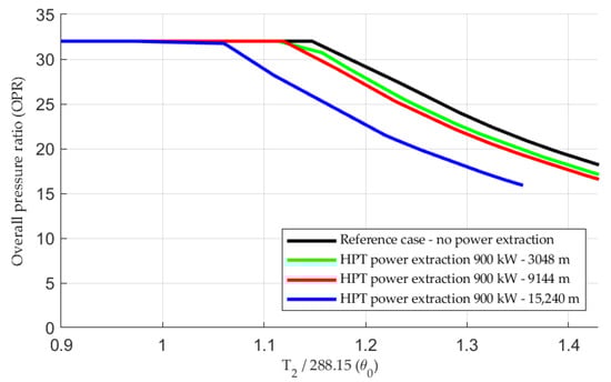
Figure 9.
Maximum augmented power. OPR versus θ0 with and without HPT power extraction. OPR versus θ0 is plotted for cases with HPT power extraction for altitudes 3048 m, 9144 m and 15,240 m for comparison.
Figure 9 shows that the engine design, defined by the design point, has a θ0 break well beyond 1, making it appropriate for high power extraction. If the θ0 break were located more to the left, the T4 limiter would become active at lower T2 (at lower Mach numbers).
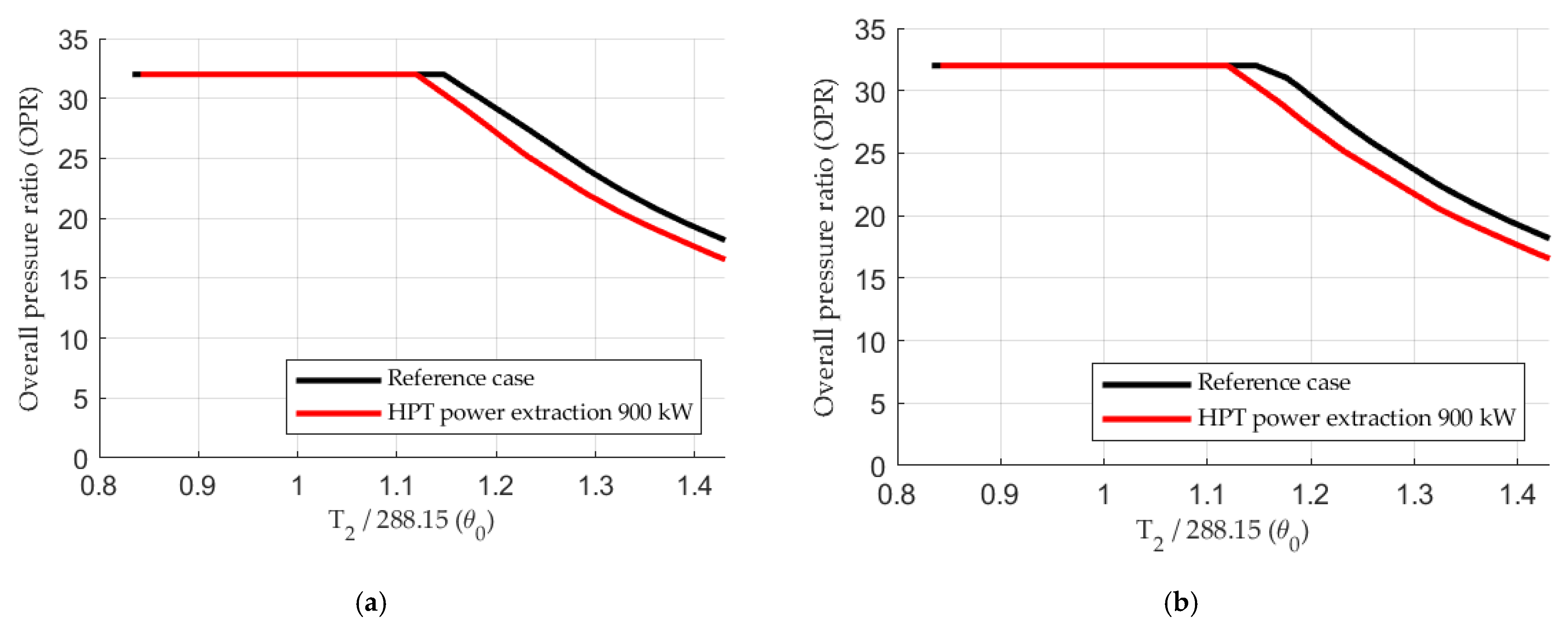
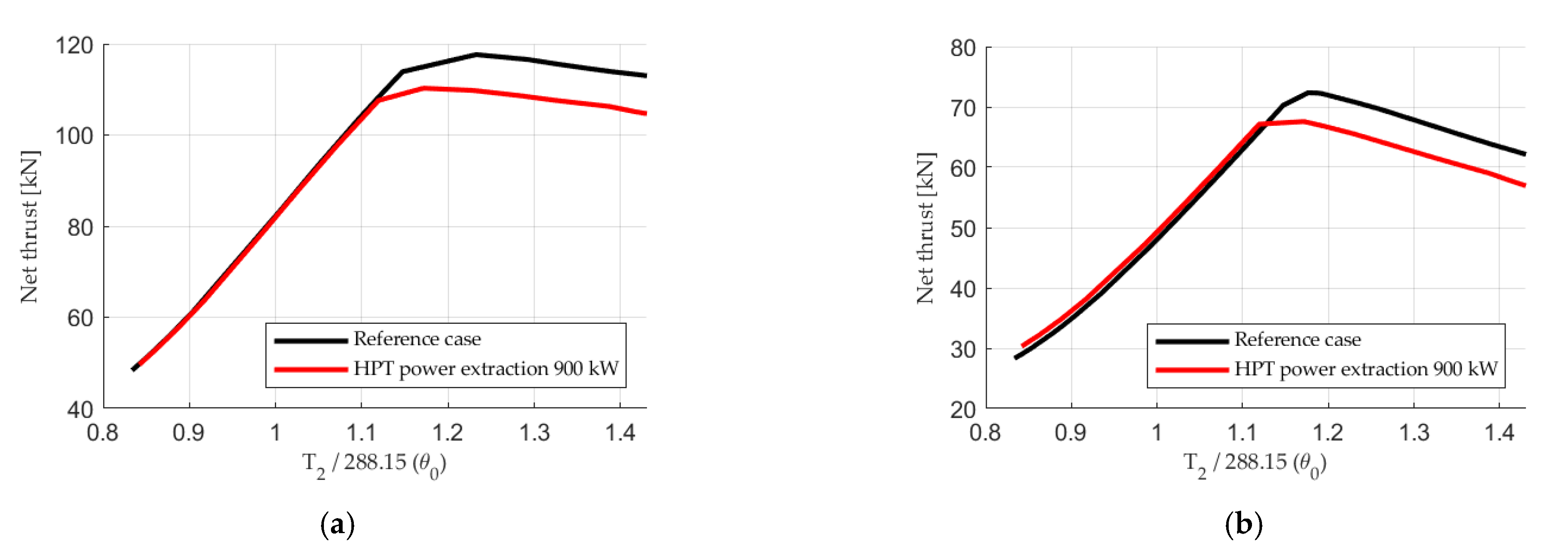
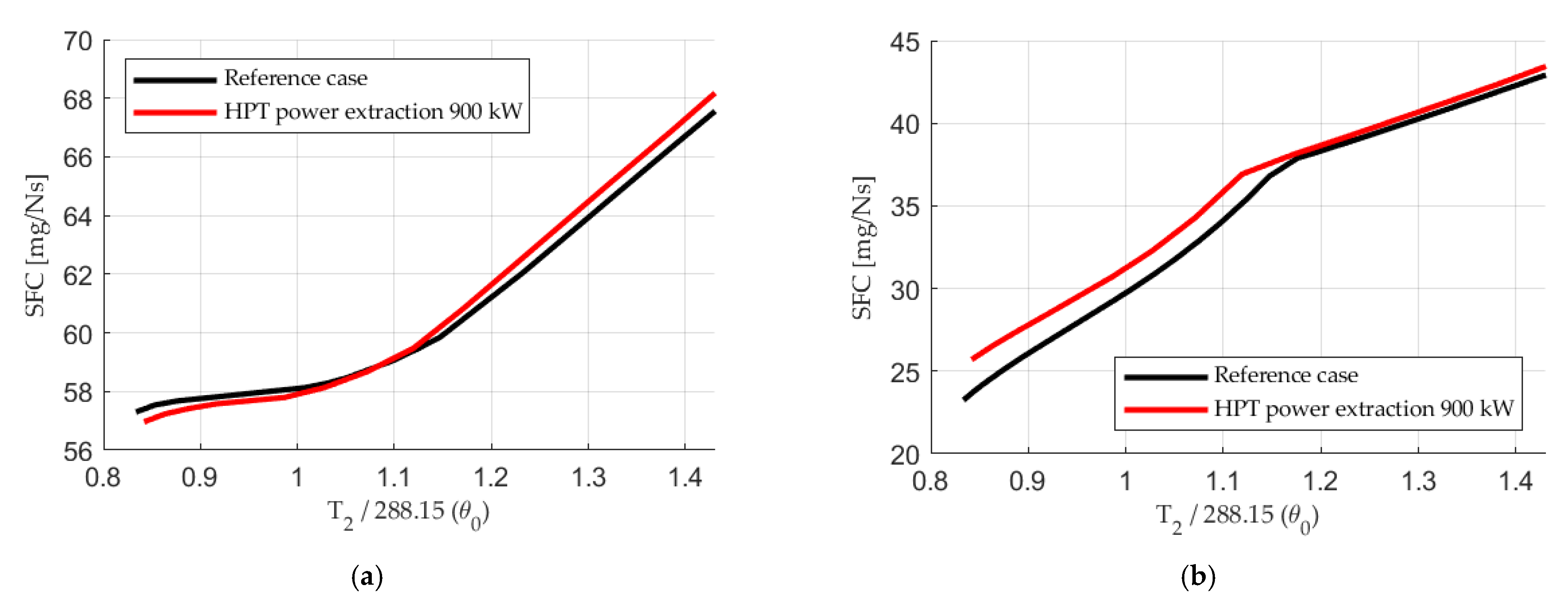
Figure 10a, Figure 11a and Figure 12a illustrate OPR, net thrust and SFC as a function of θ0 (various Mach number) with the engine running at maximum augmented power at 9144 m altitude. The figures confirm the previous conclusions that net thrust and SFC can be maintained, or even improved, if the operating point allows for a sufficient T4 increase.
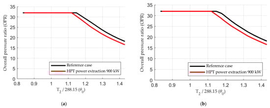
Figure 10.
OPR plotted versus θ0 (Tt2/288.15); (a) Maximum augmented power; (b) Maximum non-augmented power.
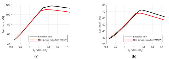
Figure 11.
Net thrust plotted versus θ0 (Tt2/288.15); (a) Maximum augmented power; (b) Maximum non-augmented power.
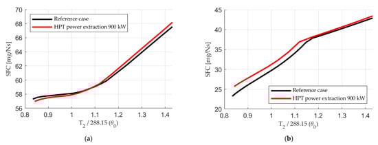
Figure 12.
SFC plotted versus θ0 (Tt2/288.15); (a) Maximum augmented power; (b) Maximum non-augmented power.
Figure 10b, Figure 11b, Figure 12b show OPR, net thrust and SFC as a function of θ0 with the engine running at maximum non-augmented power at 9144 m altitude. The non-augmented power extraction case does not bring the advantage of reducing A/B fuel flow, but the figures indicate that net thrust can be maintained or even increased at the expense of increased fuel consumption if the engine is not operating near or at its T4 limit. When power is extracted from the HPT shaft, OPR decreases, thus allowing more fuel to be burned and the OPR limit to be reached again; thereby maintaining thrust. The specific power of the engine is increased when OPR is unaltered but T4 is increased.
3.2. Effect of Varying Design OPR
To evaluate whether the conclusions made in Section 3.1 hold for engines with other thermodynamic cycles, a more extensive investigation was performed where cycles with different OPR were simulated, both for the reference case without power extraction and for the power extraction case with 900 kW extracted from the HPT. Design OPR of the design points are in the range 13–40. Each design OPR includes combinations of fan pressure ratio (FPR) and high-pressure compressor pressure ratio (HPCPR). Common characteristics of the different design points are given in Table 4.
Table 4.
Common characteristics of the design points.
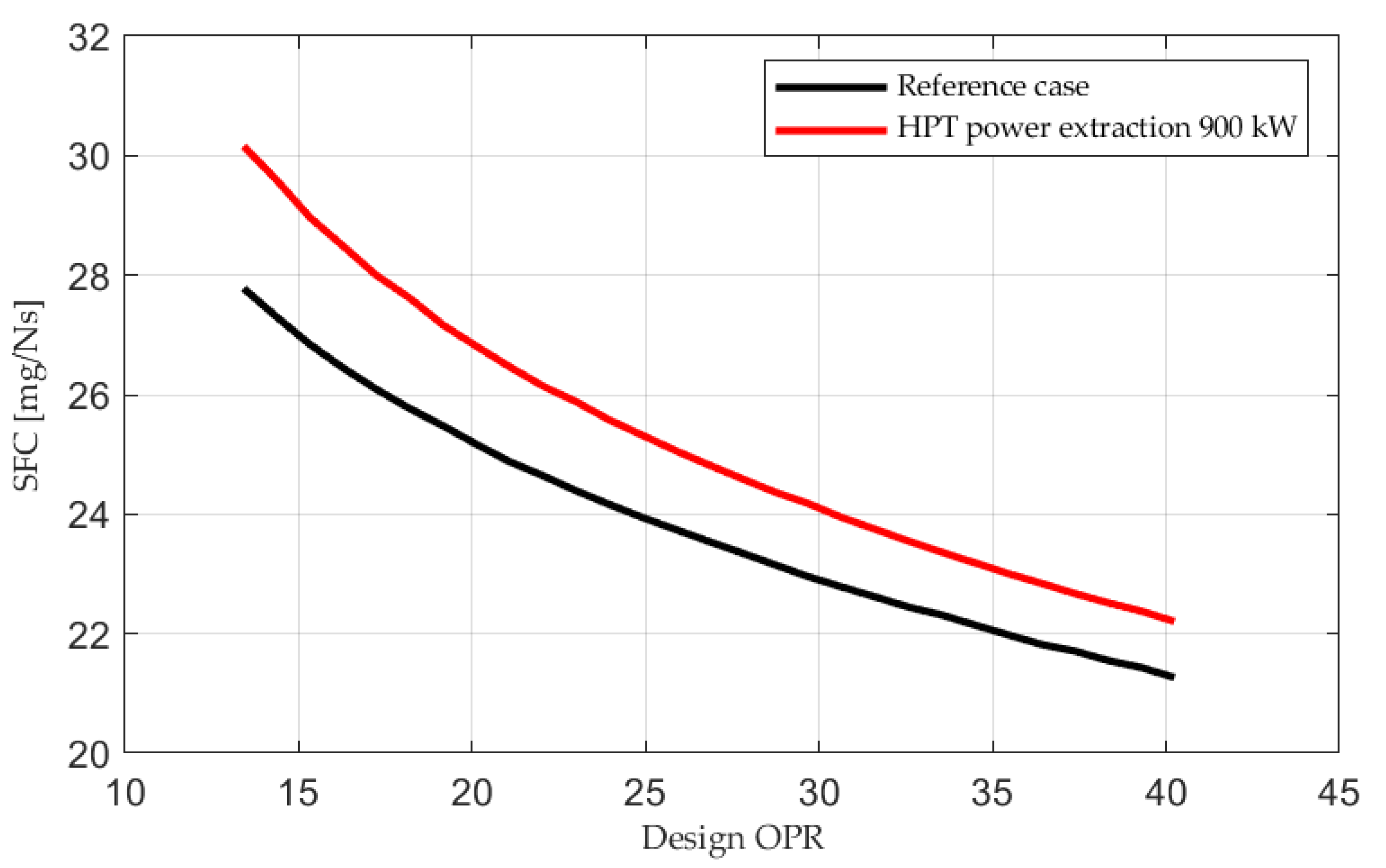
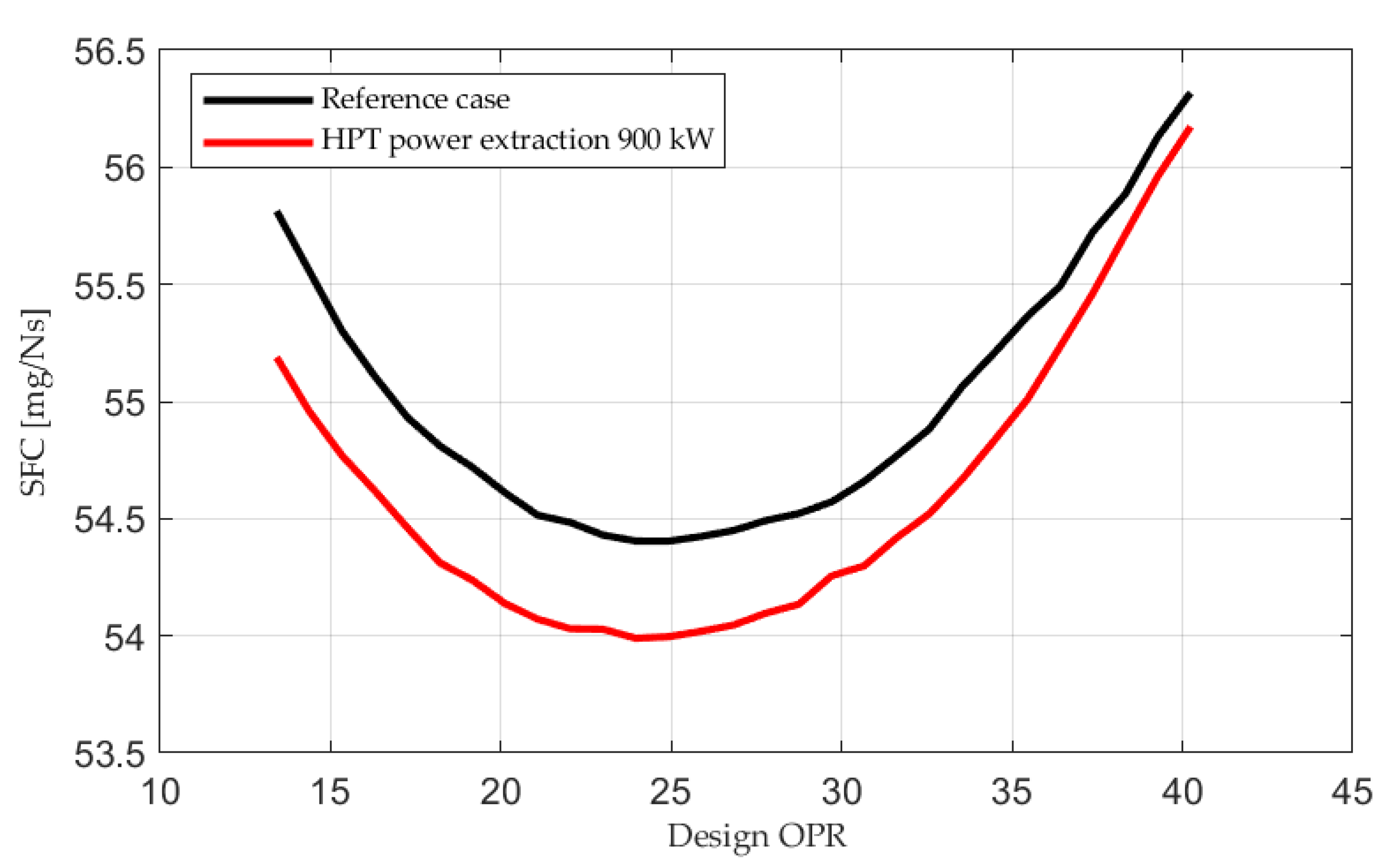
The engine controller limits OPR to the OPR specified for each design point and turbine inlet temperature to 2260 K. SFC is plotted versus design point OPR in the mission point in Figure 13 and Figure 14. Mission point 1 is shown in Figure 13 and mission point 2 is shown in Figure 14. The SFC variation with varying design OPR is in line with expectations, both at non-augmented [45,55] and augmented power [45]. The SFC values provided in Figure 13 and Figure 14 are calculated as mean values of several points with a common design OPR.
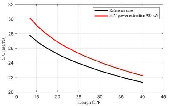
Figure 13.
Point 1 of the mission. SFC plotted versus design point OPR.
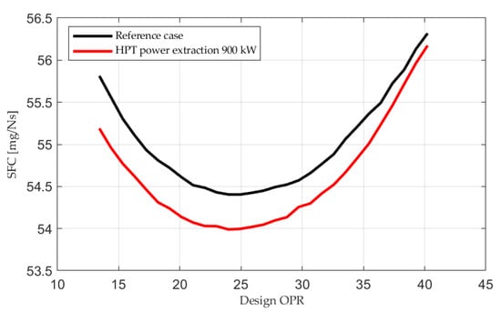
Figure 14.
Point 2 of the mission. SFC plotted versus design point OPR.
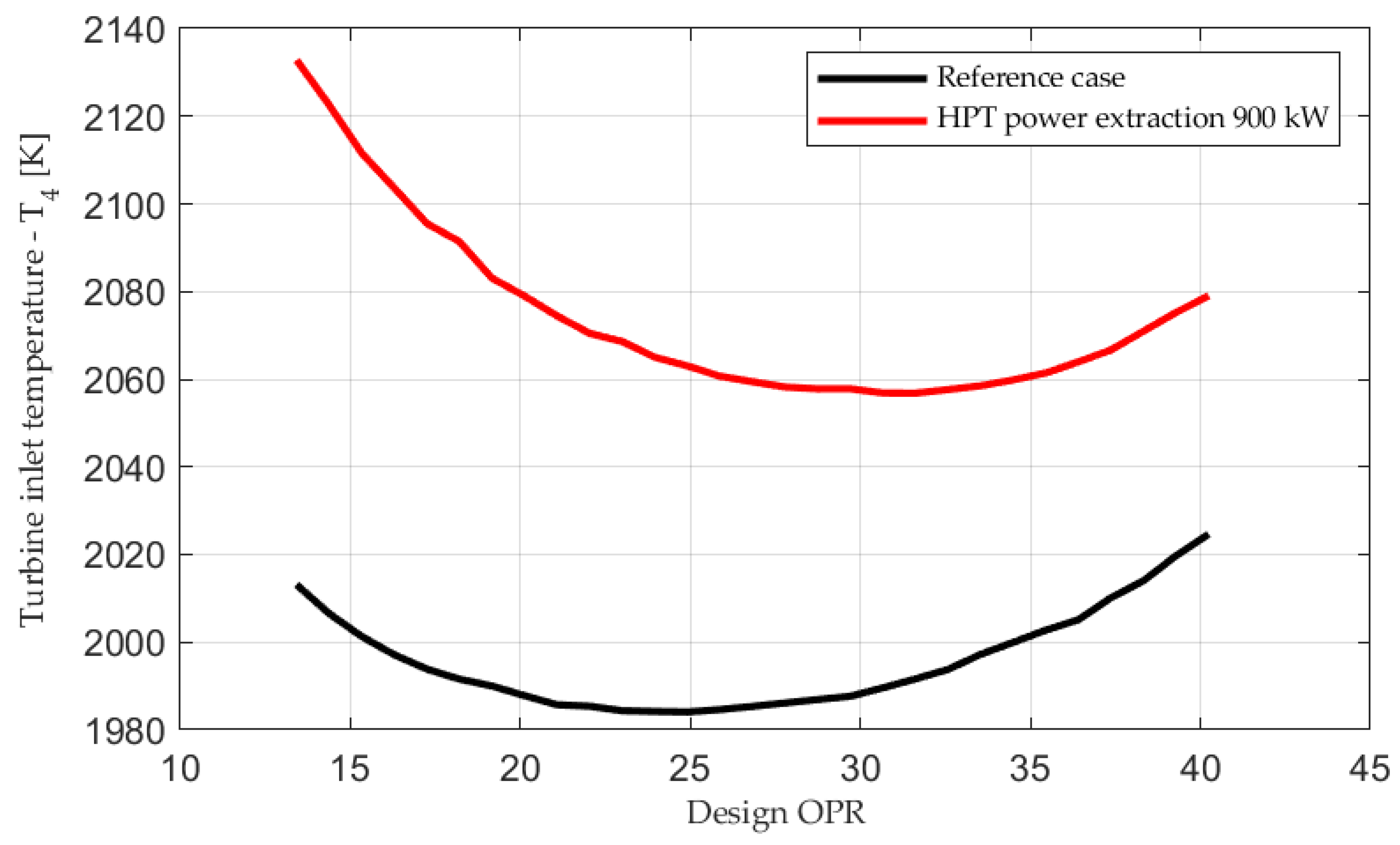
Figure 14 indicates that SFC can be improved at augmented power with different design OPRs, provided that T4 can be increased sufficiently. Figure 15 shows that a higher temperature drop is required for cycles with low OPR, thus indicating that a low OPR cycle engine will run into maximum T4 limitation at lower T2 (lower Mach numbers). As shown earlier, this leads to SFC deterioration and net thrust reduction. The T4 values provided in Figure 15 are calculated as mean values of several points with a common design OPR.
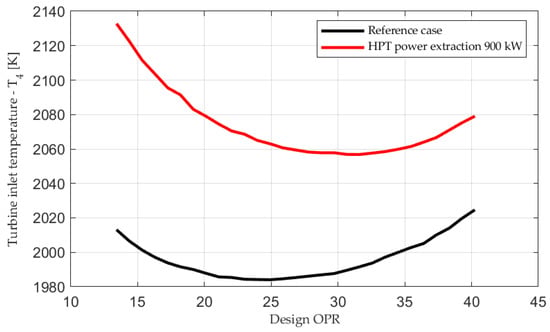
Figure 15.
Point 2 of the mission. T4 plotted versus design point OPR.
4. Discussion
Power extraction is part of the aircraft’s overall energy management and can be part of solutions to accomplish a more efficient aircraft with regards to bleed flow extraction and cooling of different subsystems [2], aircraft design and mission optimization. To identify these solutions, it is crucial to understand where the conventional turbofan engine has its potential and limitations with regards to power extraction from an engine performance perspective.
The performed investigation indicates that large HPT power extraction can be achieved at high engine power without sacrificing net thrust or SFC, provided that T4 can be increased. This in turn has important implications for the choice of thermodynamic cycle. If the θ0 break is moved to the right (i.e., θ0 > 1) the engine will have more capacity for T4 increase. By increasing T4, other costs follow, such as increased material wear and reduced engine life [5,7,50]. Nevertheless, if surge margins can be maintained at an acceptable level, the possibility to extract high HPT power at some operating conditions without too much SFC increase or net thrust reduction might have important implications with regards to both mission optimization, i.e., when to extract power from the HPT shaft, and technical solutions. For instance, if a power storage device is available, as discussed in [15,16,17,18], the analysis will help to decide when to charge and re-charge during a mission. If the thrust requirement for the escape dash is not negotiable, for example, the analysis shows that this is not a good point to extract a high amount of power; instead, it would be better to use the stored power for power consumers. A power storage device can also be used to improve stall margins and limit overspeed and T4 overshoot at transients [15]. The backside is of course the additional weight introduced with such a power storage device [17,18]. This investigation can provide guidance in a future analysis, to decide if the improved performance which could be achieved at certain parts of a mission compensates for the weight increase. Furthermore, the results can become useful in future studies to evaluate if bleed extraction from the HPC, or electric power extraction from the HPT, is the more efficient source of energy in cases where the two are interchangeable.
Author Contributions
Conceptualization, D.R. and T.G.; methodology, D.R. and T.G.; software, D.R. and T.G.; validation, D.R. and T.G.; formal analysis, D.R.; investigation, D.R.; resources, D.R. and T.G.; data curation, D.R. and T.G.; writing—original draft preparation, D.R.; writing—review and editing, D.R. and T.G.; visualization, D.R. and T.G.; supervision, T.G.; project administration, T.G.; funding acquisition, T.G. All authors have read and agreed to the published version of the manuscript.
Funding
This work has been funded by the Swedish Governmental Agency for Innovation Systems (VINNOVA), the Swedish Defense Materiel Administration (FMV) and the Swedish Armed Forces within the International Aviation Research Programme (IFFP diary number 2020-00690) and Saab Aeronautics.
Acknowledgments
I would like to express my gratitude to Pedro David Bravo-Mosquera of University of Sao Paolo, who has provided the mission for the fighter aircraft, used for evaluation in this report. I would also like to acknowledge Hans Kling, Michael Säterskog and Sebastian Arvidson at Saab for their support during the project.
Conflicts of Interest
The authors declare no conflict of interest. The funders had no role in the design of the study; in the collection, analyses, or interpretation of data; in the writing of the manuscript, or in the decision to publish the results.
Nomenclature
| A/B | Afterburner |
| ACE | Adaptive cycle engine |
| ALT | Altitude, measured in relation to sea level conditions |
| ARP | Aerospace Recommended Practice |
| BLI | Boundary layer ingestion |
| CENTRELINE | Concept validation study for fuselage wake-filling propulsion integration |
| CFS | Convertible fan stage |
| DEW | Directed energy weapon |
| EU | European Union |
| F | Force |
| Fan | Equivalent to LPC in the modeled engine |
| FN | Net thrust |
| FPR | Fan pressure ratio |
| GESTPAN | General stationary and transient propulsion analysis |
| HEP | Hybrid electric propulsion |
| LPC | Low-pressure compressor |
| HPC | High-pressure compressor |
| HPCPR | High-pressure compressor pressure ratio |
| HPT | High-pressure turbine |
| LPT | Low-pressure turbine |
| M | Mach number |
| N | Number of turns |
| OPR | Overall pressure ratio |
| PT | Stagnation pressure |
| P | Power |
| S | Entropy |
| SAE | Society of automotive engineers |
| SFC | Thrust specific fuel consumption |
| T | Stagnation temperature |
| VCE | Variable cycle engine |
| W | Mass flow |
| Β | Operating line offset relative to backbone in a compressor map |
| βf | Fuel schedule factor, off-design fuel flow relative to the design point fuel flow |
| ηp | Propulsive efficiency |
| ηth | Thermal efficiency |
| θ0 | Dimensionless stagnation temperature |
Appendix A
| ALT | M0 | PT0 | PT2 | T2 | W2 | BPR | PT3 | T3 | PT4 | T4 | PHPT | PT45 | T45 | PLPT | PT5 | T5 | PT8 | T8 | FN | ηth | ηp |
| [m] | - | [kPa] | [kPa] | [K] | [kg/s] | - | [kPa] | [K] | [kPa] | [K] | [kW] | [kPa] | [K] | [kW] | [kPa] | [K] | [kPa] | [K] | [kN] | - | - |
| 610 | 0.0 | 94.2 | 84.2 | 284 | 78.9 | 0.468 | 2280 | 782 | 2190 | 1870 | 0 | 901 | 1410 | 0 | 415 | 1200 | 410 | 991 | 66 | 0.42 | 0 |
| 610 | 0.1 | 94.9 | 86.4 | 285 | 87.6 | 0.447 | 2630 | 808 | 2530 | 1940 | 0 | 1040 | 1470 | 0 | 473 | 1250 | 399 | 2090 | 111 | 0.24 | 0.05 |
| 610 | 0.18 | 96.4 | 90.5 | 286 | 90.4 | 0.452 | 2700 | 807 | 2600 | 1930 | 0 | 1070 | 1470 | 0 | 487 | 1250 | 411 | 2090 | 113 | 0.25 | 0.1 |
| 610 | 0.44 | 108 | 104 | 295 | 104 | 0.449 | 3170 | 835 | 3050 | 2000 | 0 | 1250 | 1520 | 0 | 570 | 1300 | 489 | 2090 | 127 | 0.27 | 0.21 |
| 3048 | 0.775 | 108 | 104 | 303 | 105 | 0.44 | 3290 | 865 | 3160 | 2070 | 0 | 1300 | 1580 | 0 | 590 | 1350 | 514 | 2100 | 128 | 0.31 | 0.31 |
| 7010 | 0.875 | 67.4 | 65.5 | 280 | 65.7 | 0.455 | 1940 | 790 | 1860 | 1890 | 0 | 763 | 1440 | 0 | 348 | 1220 | 294 | 2080 | 78.9 | 0.31 | 0.33 |
| 9144 | 0.9 | 50.9 | 50.4 | 266 | 30 | 0.633 | 657 | 602 | 628 | 1370 | 0 | 257 | 1020 | 0 | 128 | 881 | 128 | 696 | 12.4 | 0.43 | 0.57 |
| 9144 | 1.6 | 127 | 115 | 346 | 88.7 | 0.498 | 2720 | 902 | 2610 | 2120 | 0 | 1080 | 1630 | 0 | 502 | 1400 | 441 | 2120 | 101 | 0.38 | 0.46 |
| 9144 | 0.9 | 50.8 | 49.7 | 266 | 45.8 | 0.485 | 1250 | 722 | 1200 | 1720 | 0 | 492 | 1290 | 0 | 227 | 1100 | 193 | 2060 | 53.2 | 0.29 | 0.34 |
| 9144 | 2.0 | 235 | 183 | 412 | 108 | 0.552 | 3320 | 985 | 3190 | 2260 | 0 | 1320 | 1750 | 0 | 634 | 1520 | 571 | 2130 | 113 | 0.38 | 0.52 |
| 610 | 0.0 | 94.2 | 84.3 | 284 | 77.7 | 0.496 | 2250 | 779 | 2170 | 1930 | 900 | 889 | 1460 | 0 | 415 | 1250 | 410 | 1020 | 66 | 0.42 | 0 |
| 610 | 0.1 | 94.9 | 86.5 | 285 | 87.1 | 0.47 | 2620 | 808 | 2520 | 2000 | 900 | 1040 | 1520 | 0 | 476 | 1300 | 408 | 2080 | 111 | 0.25 | 0.05 |
| 610 | 0.18 | 96.4 | 90.6 | 286 | 90 | 0.473 | 2700 | 807 | 2600 | 2000 | 900 | 1070 | 1520 | 0 | 491 | 1290 | 419 | 2080 | 113 | 0.25 | 0.09 |
| 610 | 0.44 | 108 | 104 | 295 | 103 | 0.467 | 3170 | 835 | 3050 | 2050 | 900 | 1250 | 1560 | 0 | 575 | 1340 | 498 | 2090 | 127 | 0.28 | 0.21 |
| 3048 | 0.775 | 108 | 104 | 303 | 105 | 0.456 | 3300 | 865 | 3170 | 2130 | 900 | 1300 | 1620 | 0 | 596 | 1390 | 524 | 2090 | 128 | 0.32 | 0.31 |
| 7010 | 0.875 | 67.4 | 65.6 | 280 | 65.5 | 0.484 | 1940 | 791 | 1870 | 1990 | 900 | 768 | 1510 | 0 | 354 | 1290 | 301 | 2080 | 78.9 | 0.32 | 0.33 |
| 9144 | 0.9 | 50.9 | 50.5 | 266 | 26.9 | 0.814 | 591 | 594 | 571 | 1680 | 900 | 233 | 1250 | 0 | 124 | 1100 | 124 | 801 | 12.4 | 0.43 | 0.55 |
| 9144 | 1.6 | 127 | 115 | 346 | 88.7 | 0.515 | 2740 | 905 | 2640 | 2190 | 900 | 1090 | 1680 | 0 | 511 | 1450 | 454 | 2110 | 101 | 0.38 | 0.46 |
| 9144 | 0.9 | 50.8 | 49.7 | 266 | 45.4 | 0.53 | 1260 | 725 | 1220 | 1870 | 900 | 498 | 1410 | 0 | 234 | 1210 | 199 | 2060 | 53.2 | 0.3 | 0.34 |
| 9144 | 2.0 | 235 | 183 | 412 | 101 | 0.589 | 3030 | 964 | 2910 | 2260 | 900 | 1200 | 1750 | 0 | 588 | 1520 | 529 | 2130 | 105 | 0.38 | 0.53 |
References
- Rosero, J.A.; Ortega, J.A.; Aldabas, E.; Romeral, L. Moving towards a more electric aircraft. IEEE Aerosp. Electron. Syst. Mag. 2007, 22, 3–9. [Google Scholar] [CrossRef] [Green Version]
- Walters, E.; Iden, S.; McCarthy, K.; Amrhein, M.; O’Connell, T.; Raczkowski, B.; Wells, J.; Lamm, P.; Wolff, M.; Yerkes, K.; et al. INVENT Modeling, Simulation, Analysis and Optimization. In Proceedings of the AIAA Aerospace Sciences Meeting Including the New Horizons Forum and Aerospace Exposition (AIAA 2010-287), Orlando, FL, USA, 4–7 January 2010; p. 3. [Google Scholar]
- Charrier, J.-J.; Kulshreshtha, A. Electric Actuation for Flight & Engine Control System: Evolution, Current trends & future Challenges. In Proceedings of the 45th AIAA Aerospace Sciences Meetings and Exhibit (AIAA 2007-1391), Reno, NV, USA, 8–11 January 2007. [Google Scholar]
- Freeman, J.; Osterkamp, P.; Green, M.; Gibson, A.; Schiltgen, B. Challenges and opportunities for electric aircraft thermal management. Aircr. Eng. Aerosp. Technol. 2014, 86, 519–524. [Google Scholar] [CrossRef]
- MacIsaac, B.; Langton, R. Gas Turbine Propulsion Systems; John Wiley and Sons Ltd.: Chichester, UK, 2011; pp. 63–65, 184–186. [Google Scholar]
- Demel, H.F. Installation of Electric Generators on Turbine Engines; 19840001994; NASA, Lewis Research Center Aircraft Elect, Secondary Power: Cleveland, OH, USA, 1983. [Google Scholar]
- Saravanamuttoo, H.I.H.; Rogers, G.F.C.; Cohen, H.; Straznicky, P.V.; Nix, A.C. Gas Turbine Theory, 7th ed.; Pearson Education Limited.: London, UK, 2017; pp. 101, 127–130, 407–408, 510. [Google Scholar]
- Rolls-Royce Plc. The Jet Engine, 5th ed.; The Technical Publication Department, Rolls-Royce Plc.: Derby, UK, 1996; p. 65. [Google Scholar]
- Guha, A. Optimisation of aero gas turbine engines. Aeronaut. J. 2001, 105, 345–358. [Google Scholar] [CrossRef]
- Roth, B.A.; Mavris, D.N. A Work Availability Perspective of Turbofan Engine Performance. In Proceedings of the 39th AIAA, Aerospace Science Meeting and Exhibit, Reno, NV, USA, 8–11 January 2001. [Google Scholar]
- Giannakakis, P.; Laskaridis, P.; Pilidis, P. Effects of Offtakes for Aircraft Secondary-Power Systems on Jet Engine Efficiency. J. Propuls. Power 2011, 27, 1024–1031. [Google Scholar] [CrossRef]
- Faidi, A. Effect of Accessory Power Take-Off Variation on a Turbofan Engine Performance; Air Force Institute of Technology, Wright-Patterson Air Force Bace: Dayton, OH, USA, 2012. [Google Scholar]
- Slingerland, R.; Zandstra, S. Bleed Air Versus Electric Power Offtakes from a Turbofan over the Flight Cycle. In Proceedings of the 7th AIAA Aviation Technology, Integration and Operations Conference (AIAA-2007-7848-925), Belfast, Northern Ireland, 18–20 September 2007. [Google Scholar]
- Samuelsson, S.; Petit, O.; Merkler, R.; Wortmann, G. Adaptation of a turbofan engine for high power offtakes for a turbo-electric propulsive fuselage concept. In Proceedings of the 24th International Symposium on Air Breathing Engines (ISABE-2019-24215), Canberra, Australia, 22–27 September 2019. [Google Scholar]
- Culley, D.E.; Kratz, J.L.; Thomas, G.L. Turbine Electrified Energy Management (TEEM) For Enabling More Efficient Engine Designs. In Proceedings of the Joint Propulsion Conference 2018, Cincinnati, OH, USA, 9–11 July 2018. [Google Scholar]
- Chapman, J.W. A Study of Large Scale Power Extraction and Insertion on Turbofan Performance and Stability. In Proceedings of the 2020 AIAA/IEEE Electric Aircraft Technologies Symposium (EATS), New Orleans, LA, USA, 26–28 August 2020. [Google Scholar]
- Van Holsteijn, M.R.; Gangoli Rao, A.; Yin, F. Operating Characteristics of an Electrically Assisted Turbofan Engine. In Proceedings of the ASME Turbo Expo 2020: Turbomachinery Technical Conference and Exposition, Online, 21–25 September 2020. [Google Scholar]
- Rafaelli, L.; Chung, J.-H.; Popovic, I. Optimisation of a High Bypass Ratio Turbofan Engine Using Energy Storage. In Proceedings of the Greener Aviation 2016, Brussels, Belgium, 11–13 October 2016. [Google Scholar]
- Mattingly, J.D. Elements of Propulsion: Gas Turbines and Rockets; American Institute of Aeronautics and Astronautics: Reston, VA, USA, 2006; p. 27. [Google Scholar]
- Guha, A. Optimum Fan Pressure Ratio for Bypass Engines with Separate or Mixed Exhaust Streams. J. Propuls. Power 2001, 17, 1117–1120. [Google Scholar] [CrossRef]
- Millhouse, P.T.; Mykytka, E.F. Identifying Optimal Fan Compressor Pressure Ratios for the Mixed-Stream Turbofan Engine. J. Propuls. Power 2000, 16, 79–86. [Google Scholar] [CrossRef]
- Nadon, L.J.P.; Kramer, S.C.; King, P.I. Multi-Objective Optimization of Mixed-Stream Turbofan Engine. In Proceedings of the 36th AIAA Aerospace Sciences Meeting and Exhibit, Reno, NV, USA, 10–13 January 1998. [Google Scholar]
- Clark, R.A.; Shi, M.; Gladin, J.; Mavris, D. Design and Analysis of an Aircraft Thermal Management System Linked to a Low Bypass Ratio Turbofan Engine. J. Eng. Gas Turbines Power 2022, 144, 011019. [Google Scholar] [CrossRef]
- Mattingly, J.D. Performance estimation of some variable bypass ratio turbofan engines. In Proceedings of the 34th AIAA/ASME/SAE/ASEE Joint Propulsion Conference and Exhibit, Cleveland, OH, USA, 13–15 July 1998. [Google Scholar]
- Meng, X.; Jang, X.-Y.; Xen, M.; Zhu, Z.-L. High Level Power Extraction from Adaptive Cycle Engine for Directed Energy Weapon. In Proceedings of the 2018 Joint Propulsion Conference, Cleveland, OH, USA, 9–11 July 2018. [Google Scholar]
- Corbett, M. Shaft Power Extraction and Waste Heat Rejection using a Three Stream Variable Cycle Engine. SAE Int. J. Aerosp. 2012, 5, 371–385. [Google Scholar] [CrossRef]
- Kurzke, J. How to Create a Performance Model of a Gas Turbine from a Limited Amount of Information. In Proceedings of the ASME Turbo Expo 2005: Power for Land, Sea, and Air, Reno, NV, USA, 6–9 June 2005; pp. 145–153. [Google Scholar]
- Mattingly, J.D. Performance Estimation of the Mixed Flow, Afterburning, Cooled, Two-Spool Turbofan Engine with Bleed and Power Extraction. In Proceedings of the AIAA/ASME/SAE/ASEE 22nd Joint Propulsion Conference, Huntsville, AL, USA, 16–18 June 1986. [Google Scholar]
- Rangwala, H.S.; Wilson, D.R. Simulation of a Low-Bypass Turbofan Engine with an Ejector Nozzle using NPSS. In Proceedings of the AIAA Propulsion and Energy Forum, Atlanta, GA, USA, 10–22 July 2017. [Google Scholar]
- Rodriguez, L.F.; Botez, R.; Mihaela, G. New Modeling Technique for Turbofan Engine Thrust. J. Propul. Power 2013, 29, 1492–1495. [Google Scholar] [CrossRef]
- Visser, W.P.J. Generic Analysis Methods for Gas Turbine Engine Performance: The development of the gas turbine simulation program GSP. Ph.D. Thesis, Technische Universiteit Delft, Delft, The Netherland, January 2015. [Google Scholar]
- Roth, B.A.; Mavris, D.N.; Doel, D.L. Estimation of Turbofan Engine Performance Model Accuracy and Confidence Bounds. In Proceedings of the 16th International Symposium on Air Breathing Engines, Cleveland, OH, USA, 31 August–5 September 2003. [Google Scholar]
- Grönstedt, T.; Wallin, M. A Comparative Study of Genetic Algorithms and Gradient Methods for RM12 Turbofan Engine Diagnostics and Performance Estimation. In Proceedings of the Turbo Expo 2004, ASME Turbo Expo, Vienna, Austria, 14–17 June 2004. [Google Scholar]
- Tong, M.T. Using Machine Learning to Predict Core Size of High-Efficiency Turbofan Engines. In Proceedings of the ASME Turbo Expo 2019, Turbomachinery Technical Conference and Exposition, Phoenix, AZ, USA, 17–21 June 2019. [Google Scholar]
- Strusnik, D. Integration of machine learning to increase steam turbine condenser vacuum and efficiency through gasket resealing and higher heat extraction into the atmosphere. Int. J. Energy Res. 2021, 2. [Google Scholar] [CrossRef]
- Grönstedt, T. Development of Methods for Analysis and Optimization of Complex Jet Engine Systems. Ph.D. Thesis, Chalmers University of Technology, Göteborg, Sweden, 2000. [Google Scholar]
- Saravanamuttoo, H.I.H. Steady and transient performance prediction of gas turbine engines. AGARD-LS-183 1992, 1, 1–18. [Google Scholar] [CrossRef]
- Broyden, C.G. A Class of Methods for Solving Nonlinear Simultaneous Equations. Math. Comp. 1965, 19, 577–596. [Google Scholar] [CrossRef]
- Broyden, C.G. A new method for solving nonlinear simultaneous equations. Comp. J. 1969, 12, 94–99. [Google Scholar] [CrossRef] [Green Version]
- Press, W.H.; Teukolsky, S.A.; Vetterling, W.T. Numerical Recipes in FORTRAN: The Art of Scientific Computing; Cambridge University Press: Cambridge, UK, 1992. [Google Scholar]
- Bravo-Mosquera, P.D. Aerodynamic design and optimization for the future fighter for the 2030–2040 timeframe. MISSION ANALYSIS. 2021. [Google Scholar]
- Mattingly, J.D.; Heiser, W.H.; Pratt, D.T. Aircraft Engine Design, Second ed.; AIAA Education Series; AIAA: Reston, NV, USA, 2002; pp. 17, 123, 172, 341, 525, 526. [Google Scholar]
- Grieb, H. Projektierung von Turboflugtriebverken; Springer: Basel, Switzerland, 2004; pp. 562–564, 735. [Google Scholar]
- Jaw, L.C.; Mattingly, J.D. Aircraft Engine Controls: Design, System Analysis, and Health Monitoring; American Institute of Aeronautics and Astronautics, Inc.: Blacksburg, VA, USA, 2009. [Google Scholar]
- Kurzke, J.; Halliwell, I. Propulsion and Power. An Exploration of Gas Turbine Performance Modeling; Springer International Publishing: Basel, Switzerland, 2018; pp. 12, 33, 34, 49, 97, 99. [Google Scholar]
- Langston, L.S. Fahrenheit 3,600. Mechan. Eng.-CIME 2007, 129, 34–37. [Google Scholar] [CrossRef] [Green Version]
- Lewis, G.M. The next European engine for combat aircraft. Aeronaut. J. 1984, 88, 5–8. [Google Scholar]
- Powel, S.F. On the Leading Edge: Combining Maturity and Advanced Technology on the F404 Turbofan Engine. J. Eng. Gas Turbines Power 1991, 113, 1–10. [Google Scholar] [CrossRef]
- Oyori, H.; Morioka, N.; Kakiuchi, D.; Shimomura, Y.; Onishi, K.; Sano, F. System Design for the More Electric Engine Incorporated in the Electrical Power Management for More Electric Aircraft; SAE Technical Paper 2012-01-2169; SAE: Warrendale, PA, USA, 2012. [Google Scholar]
- Oates, G.C. Aircraft Propulsion Systems Technology and Design; Second Printing; American Institute of Aeronautics and Astronautics: Washington, DC, USA, 1989; pp. 7, 8, 50, 64. [Google Scholar]
- Kurzke, J. The Mission Defines the Cycle: Turbojet, Turbofan and Variable Cycle Engines for High Speed Propulsion. RTO-EN-AVT-185-02; ADA596249; NATO Research and Technology Organisation: Dachau, Germany, September 2010; pp. 2–16. [Google Scholar]
- Olsson, U. Aerospace Propulsion from Insects to Spaceflight, 2nd ed.; Volvo Aero Corporation: Trollhättan, Sweden, 2012; p. 432. [Google Scholar]
- Aziz, M.A.; Owis, F.M.; Abdelrahman, M.M. Preliminary Design of Transonic Fan for Low By-Pass Turbofan Engine. Int. Rev. Aerosp. Eng. 2013, 6, 115. [Google Scholar]
- Mastropierro, F.S.; Sebastiampillai, J.; Jacob, F.; Rolt, A. Modelling geared turbofan and open rotor engine performance for year-2050 long-range and short-range aircraft. J. Eng. Gas Turbines Power 2019, 142, 14–37. [Google Scholar]
- El-Sayed, A.F. Aircraft Propulsion and Gas Turbine Engines, 2nd ed.; Taylor & Francis: Abingdon, UK, 2017; pp. 279, 286. [Google Scholar]


Publisher’s Note: MDPI stays neutral with regard to jurisdictional claims in published maps and institutional affiliations. |
© 2022 by the authors. Licensee MDPI, Basel, Switzerland. This article is an open access article distributed under the terms and conditions of the Creative Commons Attribution (CC BY) license (https://creativecommons.org/licenses/by/4.0/).