Article

Discrete Element Simulation of Interaction between Hydraulic Fracturing and a Single Natural Fracture

Rock Mechanics Engineering Division, Faculty of Engineering, Tarbiat Modares University, Tehran 14115-111, Iran
*
Author to whom correspondence should be addressed.
Fluids 2019, 4(2), 76; https://doi.org/10.3390/fluids4020076
Submission received: 5 March 2019 / Revised: 29 March 2019 / Accepted: 15 April 2019 / Published: 17 April 2019

Abstract

:
Hydraulic fracturing (HF) treatment is performed to enhance the productivity in the fractured reservoirs. During this process, the interaction between HF and natural fracture (NF) plays a critical role by making it possible to predict fracture geometry and reservoir production. In this paper, interaction modes between HF and NF are simulated using the discrete element method (DEM) and effective parameters on the interaction mechanisms are investigated. The numerical results also are compared with different analytical methods and experimental results. The results showed that HF generally tends to cross the NF at an angle of more than 45° and a moderate differential stress (greater than 5 MPa), and the opening mode is dominated at an angle of fewer than 45°. Two effects of changing in the interaction mode and NF opening were also found by changing the strength parameters of NF. Interaction mode was changed by increasing the friction coefficient, while by increasing the cohesion of NF it was less opened under a constant injection pressure.

1. Introduction

Hydraulic fracturing (HF) is a widely used well-stimulation technique for enhancing the productivity in the petroleum industry. This technique is applied in low-permeability reservoirs even in the fractured reservoirs. Extensive field observations showed that many reservoirs contain preexisting natural fractures (NF). In addition, the characterization of the fracture network for evaluating fracturing operations and for predicting reservoir performance is a common challenge for petroleum-fractured reservoirs. Characterizing stimulated fractured reservoirs is challenging because of complexities such as dual-porosity effects, multiphase flow, complex flow regimes, complex fracture geometry, the role of natural fractures, liquid loading, and operational complexities [1,2]. There are some methods for characterizing the fracture network. The most common methods for fracture characterization are pressure-transient analysis, rate-transient analysis, microseismic analysis, and tracer test. These methods are widely used by industries, and each has its own pros and cons which is discussed by Zolfaghari et al. [3].
The NF may result in a substantial difference in the HF propagation geometry. The interaction between HF and NF is a complex process. When HF intersects a NF, it can cross or be arrested by the NF; and the HF can subsequently open (dilate) the NF (Figure 1). First, the fracture tip reaches the interface, but the fluid front remains further back due to the fluid lag. At this moment, the net fluid pressure (the difference between the fracturing fluid pressure and the minimum in situ stress) at the intersection point can be considered zero, but the natural fracture is already under the influence of the stress field generated by the hydraulic fracture. This step can be analyzed by the mechanical interaction between the hydraulic fracture and the natural fracture without considering fluid flow. There are two possible outcomes from this interaction: one is slippage or arrest (Figure 1b), and the other is crossing (Figure 1c). Shortly thereafter, the second step in the process occurs when the fluid front reaches the natural fracture, and fluid pressure at the intersection point rises. In the case of slippage, the fluid may flow into and dilate the natural fracture if the fluid pressure is larger than the normal compressive stress on the natural fracture. If the flow continues, the dilated natural fracture becomes part of a hydraulic fracture network (Figure 1d); i.e., the hydraulic fracture turns and propagates along the natural fracture [4].
These interaction modes depend on the in situ stresses, the orientation of induced fracture with respect to the NF, mechanical properties of the rock, properties of NF, and the HF treatment parameters, including fracturing fluid properties and injection rate. In this regard, several works have been published in three categories of experimental [5,6,7,8,9,10,11,12], analytical [13,14,15,16], and numerical methods [17,18,19,20,21,22,23].
Warpinski et al. [5,6] found that the growth and geometry of hydraulic fractures were affected by the stress, joints, faults, interfaces and layer material property. Much research has studied factors affecting HF with the development of laboratory equipment and construction of True-Triaxial test devices [7,8,9,10,11,12]. Zhou et al. [7] also studied the interaction between HF and NF through a series of experiments and presented the crossed boundary based on different stress regimes. Sarmadivaleh et al. [8] investigated the influences of interface cohesion and approach angle on the interaction between NF and HF. Dehghan et al. [9,10] studied the effect of dip direction of NF on HF propagation as well as stress state and approach angle. Guo et al. [11] studied several factors including the type of injecting fracturing fluids, pump flow rate, fracturing pressure curve characteristics, and fracture morphology. Chen et al. [12] focused on the effects of the notch angle, notch length, and injection rate on hydraulic fracturing.
Many studies have been conducted on the effect NF on HF using different numerical methods.
Dahi-Taleghani and Olson [17] presented a numerical model based on the extended finite-element method (XFEM) as a design tool that can be used to optimize treatment parameters under complex propagation conditions. Sesetty and Ghassemi [18] presented a boundary element-based method for modeling the interaction modes. Their results showed the complexity of the propagation process and its impact on stimulation design and proppant placement. Behina et al. [19,20] studied the mechanical activation of a NF because of the propagation of the HF using displacement discontinuous method (DDM). Their results displayed before the HF reaches a NF, and the fracture re-initiation across the NF and with an offset is probable. Liu et al. [21] presented a fully coupled finite-element method (FEM)-based hydraulic-geomechanical fracture model accommodating gas sorption and damage to better understand the interaction between hydraulic fracture and oriented perforation. Liu et al. [22] developed a hybrid finite volume and XFEM for simulating hydro-fracture propagation in quasi-brittle materials. Han et al. [23] adopted a modified fluid-mechanically coupled algorithm in the Particle Flow Code (PFC2D) to study the influence of grain size heterogeneity and in situ stress on hydraulic fracturing behavior. They found that the initiation and breakdown pressure are gradually reduced with the increase of the grain size heterogeneity.
The above brief introduction indicates the complexity of the interaction between HF and NF. In order to understand the interaction mechanism and the importance of each parameter, it is necessary to conduct a fundamental study on simple cases first. Hence, in this paper, a single NF with different orientations is considered for investigating the interaction mechanism by changing the state of in situ stresses, approach angle, and NF strength properties (which is the weakness of previous research). To achieve this aim, more than 60 numerical models were simulated using the discrete element method (DEM). Finally, the numerical results were compared and discussed with analytical methods.

2. Analytical Methods

Various authors have provided analytical equations and numerical solutions for predicting the interaction between a natural fracture and hydraulic fracture. Blanton [13] derived fracture interaction criteria relating differential stress and angle of approach. Renshaw and Pollard [14] provided a criterion for crossing unbonded interfaces. Sarmadivaleh and Rasouli [16] developed a criterion for non-orthogonal cohesive fracture. In this section, these analytical criteria are presented.
Blanton [13] presented a simple analytical fracture interaction criterion on differential stress and angle of interaction to extrapolate the laboratory results to field simulations (Figure 2).
where σH and σh are the maximum and minimum principal stress acting on the plane of the NF as shown in Figure 2. θ is the angle of interaction, and T0 is tensile strength of NF. The criterion is based on the elastic solution of stresses in the interaction zone. The final equation for crossing is given by Blanton as [13]:
( σ H σ h ) T 0 < 1 cos 2 θ b sin 2 θ
When no slippage zone or no-slip occurs, b approaches infinity which term b tends to:
b = 1 2 π ln [ 1 + ( 1 + e π 2 μ f ) 0.5 1 ( 1 + e π 2 μ f ) 0.5 ] 2
and b becomes a function of the NF friction coefficient (μf). Blanton used this value for comparison of his analytical and experimental results.
and b becomes a function of the natural fracture friction coefficient. Blanton used this value to compare his analytical and experimental results.
Renshaw and Pollard [13] developed a simple criterion for predicting if a fracture will propagate across a frictional interface orthogonal to the fracture based on the linear elasticity fracture mechanics solution for the stresses near the fracture tip. It determines the stresses required to prevent slip along the interface at the moment when the stress on the opposite side of the interface is sufficient to reinitiate a fracture. Because the approach angle has a significant effect on the crossing, the Renshaw and Pollard criterion were extended to fracture intersection at non-orthogonal angles by Gu and Weng [15]. Later, Sarmadivaleh and Rasouli [16] developed Renshaw and Pollard criterion in the form a single analytical formula for a non-orthogonal cohesive fracture as the following formula:
σ n ( T 0 σ T ) < ( 1 sin θ 2 sin 3 θ 2 ) + 1 μ f cos θ 2 ( | sin θ 2 cos θ 2 cos 3 θ 2 + α | ) ( 1 + sin θ 2 sin 3 θ 2 )
where σn and σT are the normal and shear stress acting on the NF as shown in Figure 2, respectively. In the Equation (3), μ f = μ f + μ f , and μ f and α can be calculated using:
μ f = τ 0 σ n ( ( 1 sin θ 2 sin 3 θ 2 ) ( 1 sin θ 2 sin 3 θ 2 ) + 1 μ f cos θ 2 | ( sin θ 2 cos θ 2 cos 3 θ 2 + α ) | 1 )
α = τ T 0 σ T cos θ 2 ( 1 + sin θ 2 sin 3 θ 2 )
where τ0 is the shear strength of NF. Transformation of in situ stresses on the plane of NF is illustrated in Figure 2. Shear (τ), tangential (σT), and normal stresses (σn) applied along the interface can be calculated from [24]:
τ = σ H σ h 2 sin ( π 2 θ )
σ n = σ H + σ h 2 + σ H σ h 2 cos ( π 2 θ )
σ T = σ H + σ h 2 σ H σ h 2 sin ( π 2 θ )

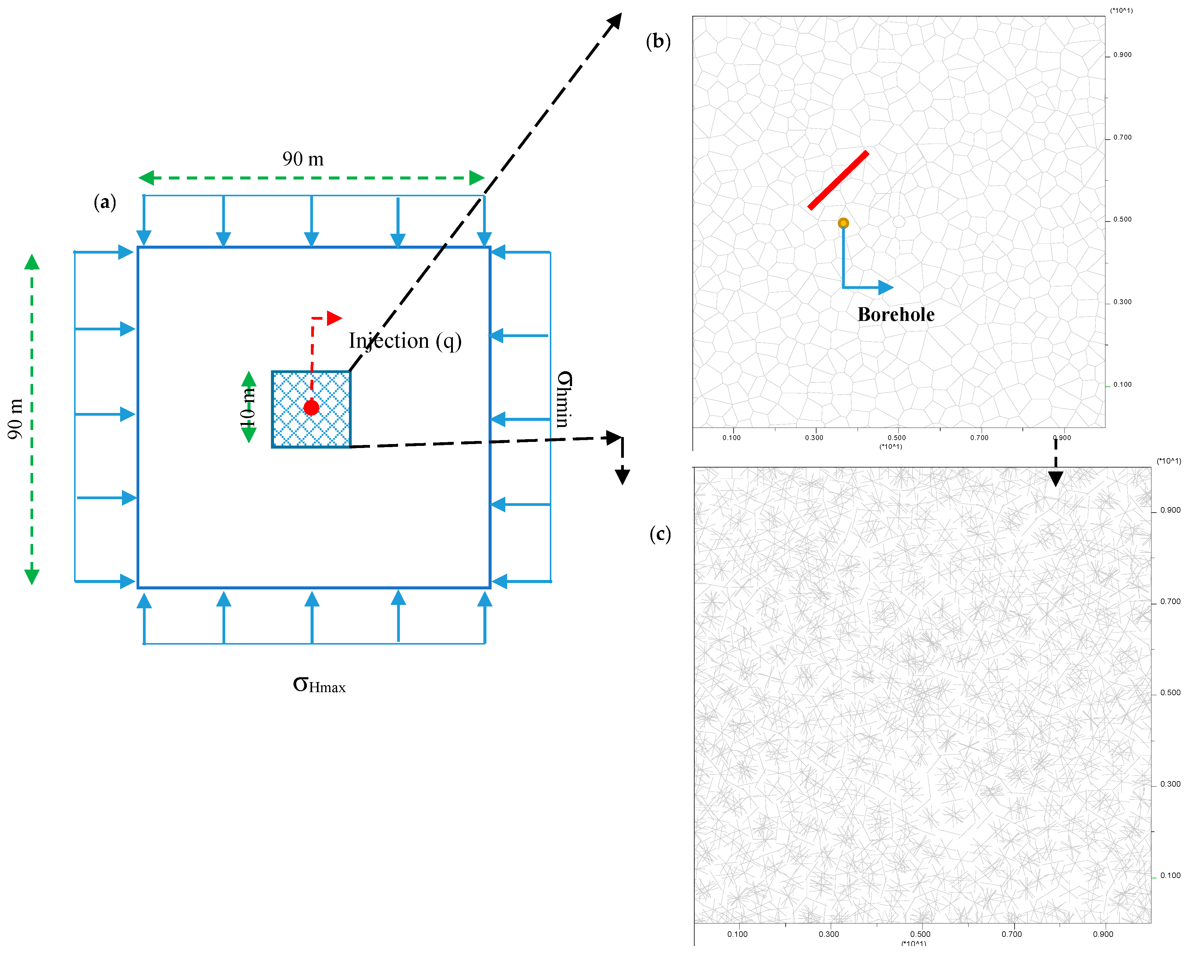
3. Numerical Modeling

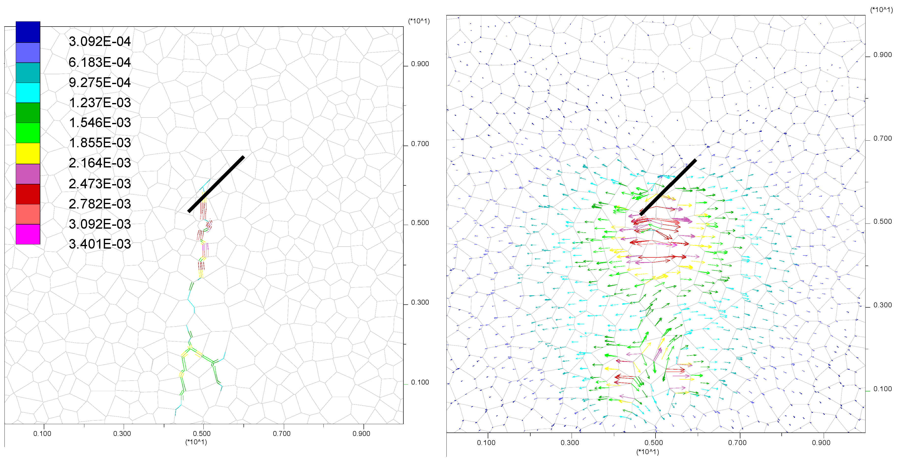
3.1. Discrete Element Method (DEM) for Simulating Hydraulic Fracturing (HF)

In this paper, DEM is used for investigating the effect of a single fracture on HF propagation. The DEM method was originated by Cundall [25] and gradually evolved to the Universal Distinct Element Code (UDEC) and 3 Dimensional Distinct Element Code (3DEC) for solving 2D and 3D problems, respectively. The mechanical interaction between blocks is captured by a compliant contact model that accommodates virtual “interpenetrations” governed by assumed finite stiffnesses to derive normal and tangential contact forces. In this model, the increments of normal stress ∆σn and the tangential stress ∆τ can be calculated from the relative motion of bonded blocks, and are given by [26]:
Δ σ n = K n Δ u n
Δ τ = K s Δ u s
where Kn and Ks are the normal and shear stiffness, respectively; ∆un and ∆us are the increments of normal displacement and shear displacement in a time step, respectively.
The DEM approach is able to capture the stress-strain characteristics of intact rocks, the opening/shearing of pre-existing fractures and the interaction between multiple blocks and fractures. Combined with discrete fracture network (DFN) models, it has been widely applied to study the mechanical behavior of fractured rocks. This is a rule-based approach which bypasses many of the complex numerical, geometrical and practical challenges of numerical methods [27].
Since UDEC can model fracture propagation along the predefined planes only, all potential fracture pathways must be pre-defined. To incorporate this limitation and provide added degrees of freedom for fracture propagation, a Voronoi tessellation scheme can be used to generate randomly sized polygonal blocks [28]. Therefore, the Voronoi elements with equivalent parameters of intact rock “i.e., (cohesion, φ, tension)DFN = (cohesion, φ, tension)intact rock” as well as appropriate stiffness (Kn and Ks) were used in this study.
Mechanical deformation of joint apertures changes conductivity, and the blocks in this assemblage are treated as being impermeable. The cubic law for flow within a planar fracture is used, where the flow rate (q) is given by [26]:
q = k a 3 Δ P l ; k = 1 12 μ
where, k is a joint conductivity factor, a is the contact hydraulic aperture, ΔP is the pressure difference between the two adjacent domains, l is the length assigned to the contact between the domains, and µ is fluid dynamic viscosity. Furthermore, the fracture flow is idealized by means of a parallel plate model and cubic law, which disregards tortuosity.
The hydro-mechanical coupling is considered by associating the hydraulic aperture to the mechanical joint stiffness and acting effective normal stresses. During the fluid flow calculation, the increment of fluid pressure (∆P) in a reservoir is computed from the bulk modulus of fluid (Kf), the volume of the domain (Vd), the sum of the flow volume for one time step (∆t), and the volume change of the domain due to mechanical loading according to Equation (12) [26]:
Δ P = K f V d ( q Δ t Δ V d )
Reservoir deformations are caused by the fluid pressure exerted on the surrounding media. This force (f) is a product of fluid pressure (Pf), the length (l) exposed to fluid in a domain, and unit thickness (1 m) in an out-of-plane direction.
Figure 3a–c show the boundary conditions, DFN model (Voronoi Elements), and contact elements related to discrete blocks, respectively. 3871 contacts elements are used in the numerical modeling. The Mohr–Coulomb and Coulomb criteria are considered for behavior model of rock mass and joints, respectively. The fluid viscosity is 1 × 10³ Pa.s. Table 1 illustrates the rock mechanical parameters of fractures network and NF.

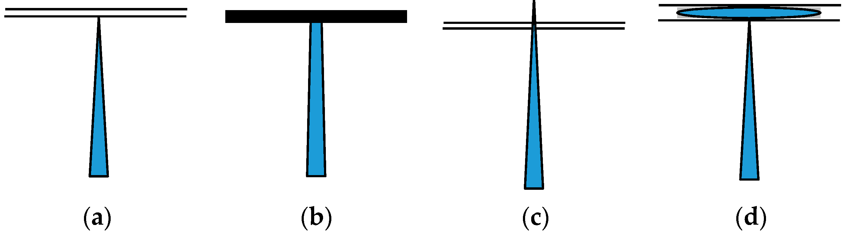
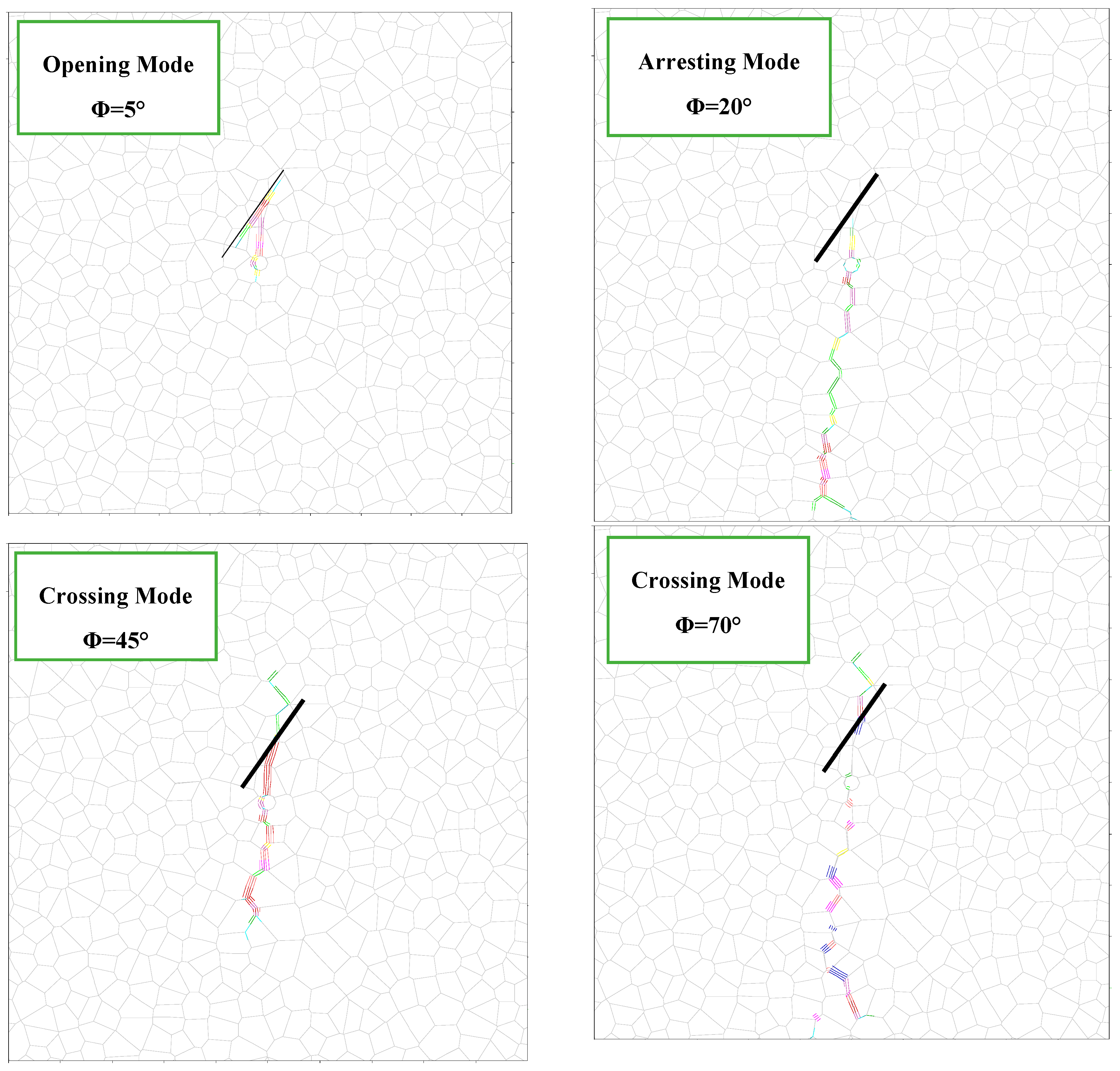
3.2. Interaction Modes in DEM Simulation

3.2.1. Opening Mode

The first interaction scenario usually happens when the approach angle is low. In this case, HF is propagated along the NF, and then it is opened. For instance, the opening mode is shown in Figure 4 with an incidence angle of 45° under low differential stresses (σ1 − σ3 = 1 MPa). The displacement vectors clearly approve the opening mode in this condition.

3.2.2. Arresting Mode

The second interaction scenario indicating an arresting response was observed when the HF approached the NF with an angle of 45° under intermediate differential stress conditions (Δσ = 10 MPa). Figure 5 shows joint opening and displacement vectors in this condition. In the arresting mode, HF is stopped in the intersection with NF, and then it propagates from the other side of a wellbore with continuing injection during the time (according to Figure 5 and displacement vectors).

3.2.3. Crossing Mode

If the HF crosses the NF, it remains planar with the possibility to open the intersected NF if the fluid pressure at the intersection exceeds the normal stress acting on the NF. An example where the numerical modeling produced a hydraulic fracture that crossed a preexisting NF is presented in Figure 6. This figure shows the joint opening and displacement vectors in this condition. In this case, the HF approaches the natural fracture with an incidence angle of 90° under high differential stresses (σ1 − σ3 = 15 MPa) and finally crosses the NF along the direction of maximum principal stress.

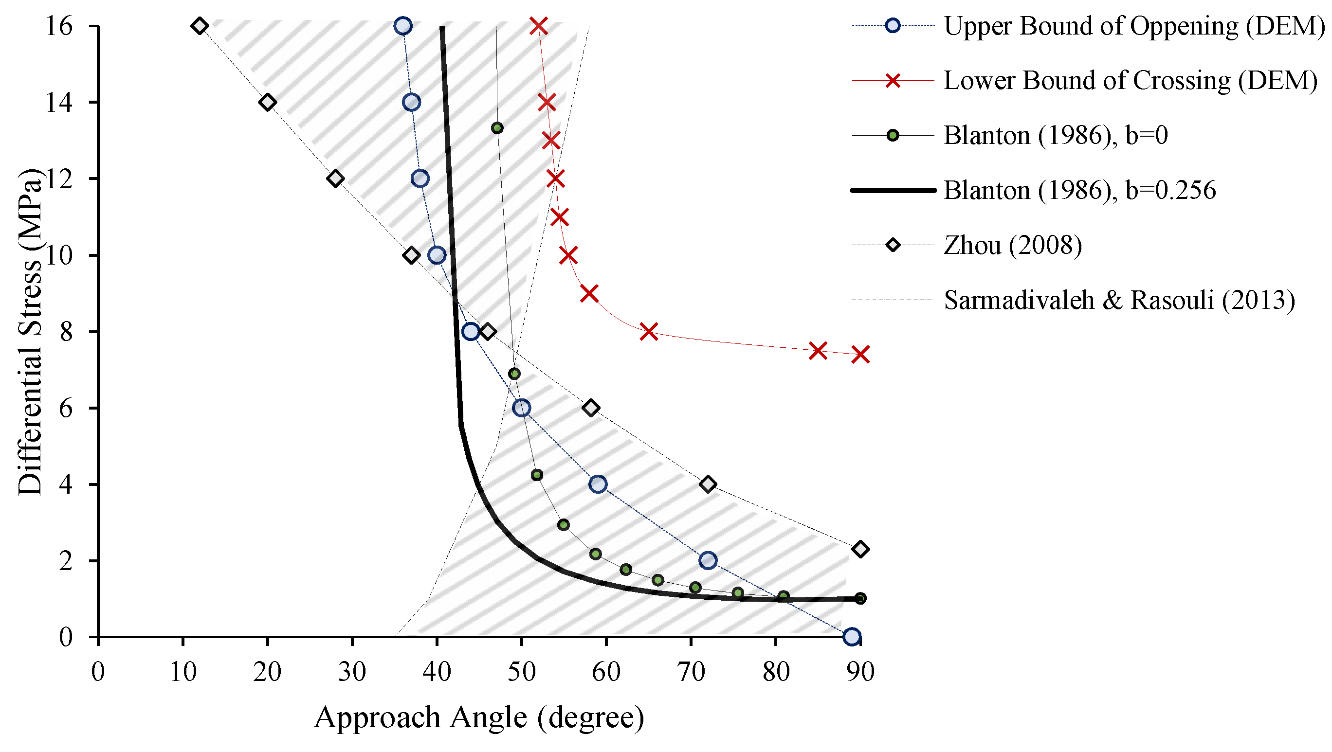
3.3. Comparison of Different Methods

The boundary of three regions of interaction modes was determined based on numerical simulation results described in the previous sections. Based on these results, we identified a clear region of opening and crossing interactions modes, separated by a region of arresting interaction (Figure 7). Then, these results were compared with two analytical methods of Blanton [13] and Sarmadivaleh–Rasouli [16], and also the experimental results of Zhou et al. [7]. Figure 8 shows the crossed boundary of different methods. Two boundaries of maximum and minimum of “b value” in Blanton method are considered. Using Equation (2) The bmin value was considered 0 and bmax value was calculated to be 0.256.
The main difference of these methods is shown as a hatched area in Figure 8. As can be seen, in Sarmadivaleh and Rasouli’s [16] method crossing mode occurs in a medium to high approach angle (more than 45°) even in the very low differential stress while crossing mode requires a minimum differential stress in the rest methods. Regardless of the difference in these methods, it can generally be said that HF tends to cross the NF at an angle of more than 45° and a moderate differential stress (greater than 5 MPa); and the opening mode is dominated at angles less than 45°.

4. Effect of Strength Parameters of Natural Fracture (NF) on HF Propagation

Cohesion (C) and friction angle (ϕ) are two parameters of fractures that seriously affect the HF. According to numerical simulation results, these parameters have two effects on HF:
-
changing the interaction mode
-
increasing/decreasing the joint opening
Figure 9 shows the effect of friction angle on the HF propagation in the case of an incidence angle of 33° under moderate differential stresses (Δσ = 10 MPa). As can be seen, interaction mode changes from opening to arresting mode and from arresting to crossing mode as ϕ increases from 5° to 70°. This phenomenon happens because NF and rock act as a unit against fracture propagation with increasing of the friction coefficient. Indeed, with an increasing friction coefficient, more pressure is needed to open the NF. Finally, HF tends to propagate in the same initial direction (perpendicular to minimum stress).
Changing mode was not observed with increase in C values of NF in numerical simulations. Figure 10 demonstrates the effect of cohesion on HF in the condition of an incidence angle of 33° under differential stresses of 10 MPa. This effect can be found in NF values. By increasing the C values, the resistance of the joint to the opening is increased by the injection pressure; therefore, NF is less opened under a constant value of injection pressure (or constant flow rate over the same time period).
Changing the interaction mode can be observed in the analytical method of Sarmadivaleh and Rasouli [16]. Figure 11 depicts the effect of strength parameters of NF on the crossed tendency. According to this figure, crossed tendency moves to the left side of the chart, leading to widening of the crossed zone. This effect is also observed in the numerical simulation results with an increase in ϕ. In this regard, the effect of ϕ is more tangible than C based on Figure 11.

5. Conclusions

Understanding the mechanisms of interaction between NF and HF plays a key role in explaining the fracture complexity during HF treatments and, ultimately, predict fracture geometry and reservoir production. In this paper, different numerical simulations based on DEM were performed for investigating these interaction mechanisms and the effect of strength parameters of NF on HF propagation route. The numerical results also were compared with the different analytical method and experimental results. The results showed that:
  • Overall, HF tends to cross the NF at an angle of more than 45° and a moderate differential stress (greater than 5 MPa); and the opening mode is dominated at an angle less than 45°.
  • Interaction mode changes from opening to arresting mode and from arresting to crossing mode with an increase in ϕ from 5° to 70°.
  • By increasing the amount of C, the resistance of the joint to the opening is increased by the injection pressure; therefore, NF is less opened under a constant value of injection pressure.

Author Contributions

Validation, R.B., K.G.; investigation, R.B.; writing—original draft preparation, R.B.; writing—review and editing, K.G. and M.A.; visualization, R.B.; supervision, K.G.; project administration, K.G. and M.A.

Funding

This research received no external funding.

Conflicts of Interest

The authors declare no conflict of interest.

References

  1. Zolfaghari, A.; Noel, M.; Dehghanpour, H.; Bearinger, D. Understanding the Origin of Flowback Salts: A Laboratory and Field Study. In Proceedings of the SPE/CSUR Unconventional Resources Conference-Canada, Calgary, AB, Canada, 30 September–2 October 2014. [Google Scholar] [CrossRef]
  2. Xu, Y.; Ezulike, O.D.; Zolfaghari, A.; Dehghanpour, H.; Virues, C. Complementary Surveillance Microseismic and Flowback Data Analysis: An Approach to Evaluate Complex Fracture Networks. In Proceedings of the SPE Annual Technical Conference and Exhibition, Dubai, UAE, 26–28 September 2016. [Google Scholar] [CrossRef]
  3. Zolfaghari, A.; Dehghanpour, H.; Ghanbari, E.; Bearinger, D. Fracture Characterization Using Flowback Salt-Concentration Transient. SPE J. 2016, 21, 233–244. [Google Scholar] [CrossRef]
  4. Gu, H.; Weng, X.; Lund, J.; Mack, M.; Ganguly, U.; Suarez-Rivera, R. Hydraulic Fracture Crossing Natural Fracture at Non-orthogonal Angles, A Criterion, Its Validation and Applications. In Proceedings of the SPE Hydraulic Fracturing Technology Conference and Exhibition, The Woodlands, TX, USA, 24–26 January 2011. [Google Scholar]
  5. Warpinski, N.R.; Fnley, S.J.; Vollendorf, W.C.; O’Brien, M.; Eshom, E. The Interface Test Series: An In Situ Study of Factors Affecting the Containment of Hydraulic Fractures; Sandia National Laboratories Report SAND81-2408; Sandia National Laboratories: Albuquerque, NM, USA, 1982. [Google Scholar]
  6. Warpinski, N.R.; Teufel, L.W. Influence of Geologic Discontinuities on Hydraulic Fracture Propagation. J. Pet. Technol. 1987, 39, 209–220. [Google Scholar] [CrossRef]
  7. Zhou, J.; Chen, M.; Jin, Y.; Zhang, G. Analysis of fracture propagation behavior and fracture geometry using a tri-axial fracturing system in naturally fractured reservoirs. Int. J. Rock Mech. Min. Sci. 2008, 45, 1143–1152. [Google Scholar] [CrossRef]
  8. Sarmadivaleh, M.; Rasouli, V. Test Design and Sample Preparation Procedure for Experimental Investigation of Hydraulic Fracturing Interaction Modes. Rock Mech. Rock Eng. 2015, 48, 93–105. [Google Scholar] [CrossRef]
  9. Dehghan, A.; Goshtasbi, K.; Ahangari, K.; Jin, Y. Mechanism of fracture initiation and propagation using a tri-axial hydraulic fracturing test system in naturally fractured reservoirs. Eur. J. Environ. Civ. Eng. 2016, 20, 560–585. [Google Scholar] [CrossRef]
  10. Dehghan, A.; Goshtasbi, K.; Ahangari, K.; Jin, Y. The effect of natural fracture dip and strike on hydraulic fracture propagation. Int. J. Rock Mech. Min. Sci. 2015, 75, 210–215. [Google Scholar] [CrossRef]
  11. Guo, Y.; Deng, P.; Yang, C.; Chang, X.; Wang, L.; Zhou, J. Experimental Investigation on Hydraulic Fracture Propagation of Carbonate Rocks under Different Fracturing Fluids. Energies 2018, 11, 3502. [Google Scholar] [CrossRef]
  12. Chen, Y.; Meng, Q.; Zhang, J. Effects of the Notch Angle, Notch Length and Injection Rate on Hydraulic Fracturing under True Triaxial Stress: An Experimental Study. Water 2018, 10, 801. [Google Scholar] [CrossRef]
  13. Blanton, T.L. Propagation of hydraulically and dynamically induced fractures in naturally fractured reservoirs. In Proceedings of the SPE Unconventional Gas Technology Symposium, Louisville, KY, USA, 18–21 May 1986. [Google Scholar]
  14. Renshaw, C.E.; Pollard, D.D. An experimentally verified criterion for propagation across unbonded frictional interfaces in brittle linear elastic materials. Int. J. Rock Mech. Min. Sci. Geomech. Abstr. 1995, 32, 237–249. [Google Scholar] [CrossRef]
  15. Gu, H.; Weng, X. Criterion for fractures crossing frictional interfaces at non-orthogonal angles. In Proceedings of the 44th US Rock Mechanics Symposium and 5th US-Canada Rock Mechanics Symposium, Salt Lake City, UT, USA, 27–30 June 2010. [Google Scholar]
  16. Sarmadivaleh, M.; Rasouli, V. Modified Reinshaw and Pollard Criteria for a Non-Orthogonal Cohesive Natural Interface Intersected by an Induced Fracture. Rock Mech. Rock Eng. 2013, 47, 2107–2115. [Google Scholar] [CrossRef]
  17. Dahi-Taleghani, A.; Olson, J.E. Numerical modeling of multistrand hydraulic-fracture propagation: Accounting for the interaction between induced and natural fractures. SPE J. 2011, 16, 575–581. [Google Scholar] [CrossRef]
  18. Sesetty, V.; Ghassemi, A. Simulation of Hydraulic Fractures and Their Interactions with Natural Fractures. In Proceedings of the 46th U.S. Rock Mechanics/Geomechanics Symposium, Chicago, IL, USA, 24–27 June 2012. [Google Scholar]
  19. Behnia, M.; Goshtasbi, K.; Fatehi Marji, M.; Golshani, A. Numerical simulation of interaction between hydraulic and natural fractures in discontinuous media. Acta Geotech. 2015, 10, 533–546. [Google Scholar] [CrossRef]
  20. Behnia, M.; Goshtasbi, K.; Zhang, G.; Mirzeinaly Yazdi, S.H. Numerical modeling of hydraulic fracture propagation and reorientation. Eur. J. Environ. Civ. Eng. 2015, 19, 152–167. [Google Scholar] [CrossRef]
  21. Liu, L.; Li, L.; Elsworth, D.; Zhi, S.; Yu, Y. The Impact of Oriented Perforations on Fracture Propagation and Complexity in Hydraulic Fracturing. Processes 2018, 6, 213. [Google Scholar] [CrossRef]
  22. Liu, C.; Shen, Z.; Gan, L.; Jin, T.; Zhang, H.; Liu, D. A Hybrid Finite Volume and Extended Finite Element Method for Hydraulic Fracturing with Cohesive Crack Propagation in Quasi-Brittle Materials. Materials 2018, 11, 1921. [Google Scholar] [CrossRef] [PubMed]
  23. Han, Z.; Zhou, J.; Zhang, L. Influence of Grain Size Heterogeneity and In-Situ Stress on the Hydraulic Fracturing Process by PFC2D Modeling. Energies 2018, 11, 1413. [Google Scholar] [CrossRef]
  24. Jaeger, J.; Cook, N.G.; Zimmerman, R. Fundamentals of Rock Mechanics; Blackwell: Oxford, UK, 2007. [Google Scholar]
  25. Cundall, P.A. Formulation of a three-dimensional distinct element model-Part I. A scheme to detect and represent contacts in a system composed of many polyhedral blocks. Int. J. Rock Mech. Min. Sci. Geomech. Abstr. 1988, 25, 107–116. [Google Scholar] [CrossRef]
  26. Itasca Consulting Group Inc. UDEC (Version 6.0) Manual; Itasca Consulting Group Inc.: Minneapolis, MN, USA, 2016. [Google Scholar]
  27. Rogers, S.; Elmo, D.; Dunphy, R.; Bearinger, D. Understanding Hydraulic Fracture Geometry and Interactions in the Horn River Basin through DFN and Numerical Modeling. In Proceedings of the Canadian Unconventional Resources and International Petroleum Conference, Calgary, AB, Canada, 19–21 October 2010. [Google Scholar] [CrossRef]
  28. Zangeneh, N.; Eberhardt, E.; Bustin, R.M. Investigation of the influence of natural fractures and in situ stress on hydraulic fracture propagation using a distinct-element approach. Can. Geotech. 2015, 52, 926–946. [Google Scholar] [CrossRef]
Figure 1. A schematic of different interaction modes between hydraulic fracturing (HF) and natural fracture (NF). (a) Approaching HF to NF. (b) Arresting. (c) Crossing. (d) Opening.
Fluids 04 00076 g001
Figure 2. A schematic of a HF approaching a NF.
Fluids 04 00076 g002
Figure 3. (a) Dimensions in general numerical mode, (b) DFN and NF, (c) contact elements location.
Fluids 04 00076 g003
Figure 4. Opening mode in numerical modeling with an incidence angle of 45° under low differential stresses of 1 MPa.
Fluids 04 00076 g004
Figure 5. Arresting mode in numerical modeling with an incidence angle of 45° under differential stresses of 10 MPa.
Fluids 04 00076 g005
Figure 6. Crossing mode in numerical modeling with an incidence angle of 90° under differential stresses of 15 MPa.
Fluids 04 00076 g006
Figure 7. Correlation between approach angle and differential stress, based on discrete element method (DEM) simulations.
Fluids 04 00076 g007
Figure 8. Comparison crossing bound in different methods.
Fluids 04 00076 g008
Figure 9. Effect of friction angle on the HF propagation (approach angle of 33° and Δσ of 10 MPa).
Fluids 04 00076 g009
Figure 10. Effect of cohesion strength of NF on the HF propagation (approach angle of 33° and Δσ of 10 MPa).
Fluids 04 00076 g010
Figure 11. Effect of strength parameters of NF on crossed tendency based on Sarmadivaleh and Rasouli [16] method.
Fluids 04 00076 g011
Table 1. Rock mechanical properties of rock mass, discrete fracture network (DFN), and natural fracture.
Rock Mass ParameterUnitValue
Elastic ModulusGPa24
Poisson’s ratio-0.25
CohesionMPa2
Friction AngleDegree35
Tension StrengthMPa1
Fracture Parameters DFNNatural Fracture
Normal StiffnessGPa/m35020
Shear StiffnessGPa/m14010
CohesionMPa20
Friction AngleDegree3520
Tension StrengthMPa10.01

