Article

Effect of Inclination on Vortex Shedding Frequency Behind a Bent Cylinder: An Experimental Study

by
Jorge Silva-Leon
1,* and
Andrea Cioncolini
2
1
Escuela Superior Politécnica del Litoral, ESPOL, Facultad de Ingeniería en Mecánica y Ciencias de la Producción, Campus Gustavo Galindo Km 30.5 Vía Perimetral, P.O. Box 09-01-5863, Guayaquil, Ecuador
2
School of Mechanical, Aerospace and Civil Engineering, University of Manchester, George Begg Building, Sackville Street, Manchester M1 3BB, UK
*
Author to whom correspondence should be addressed.
Fluids 2019, 4(2), 100; https://doi.org/10.3390/fluids4020100
Submission received: 16 May 2019 / Accepted: 29 May 2019 / Published: 31 May 2019

Abstract

:
This paper presents experimental results on the vortex shedding frequency measured behind a bent cylinder. Experiments were conducted in a wind tunnel covering Reynolds numbers between 50 and 500, a range of interest for flow sensing, flow control, and energy harvesting applications. The bent cylinder comprised a vertical leg always oriented at normal incidence with respect to the free-stream flow, and an inclined leg whose inclination was varied during the tests between 90° and 15°. The bent cylinder was oriented in the wind tunnel with the vertical leg upstream and the inclined leg downstream, and the vortex shedding frequency was measured with hot-wire anemometry at several locations behind the inclined leg. The present bent cylinder design improves upon those previously considered by providing a finer control on the upstream boundary condition acting upon the inclined leg, which in the present design is not affected by the yaw angle of the inclined leg. With the exception of free-end effects, only noticeable for certain inclinations and Reynolds number values, inclination effects were surprisingly not observed, and the frequency of vortex shedding measured behind the inclined leg of the bent cylinder was consistent (within a few percent) with the cross-flow vortex shedding frequency at the same flow velocity. The present results corroborate and significantly extend the limited observations on bent cylinders available in the literature, further highlighting the importance of the upstream boundary condition on the vortex shedding process with inclined cylinders.

1. Introduction

Vortex shedding is the oscillating flow pattern that can be observed when a fluid flows past a body, and is characterized by a regular pattern of staggered vortices (so-called vortex street) that form and periodically detach at the back of the body. Vortex shedding is rather ubiquitous in practical applications, and can, for example, be observed with suspension cables, transmission lines, chimneys and slender structures in wind; risers and mooring cables in marine applications; bridge piers; tubes and rods in fluid machinery; aircraft and missiles under maneuvering conditions; and vegetation in wind or water flow. As is well known, the periodic shedding of vortices induces a periodic fluctuation of the fluid forces acting on the body, which in turn can trigger vortex-induced vibration if the body is flexible or otherwise free to oscillate. The practical relevance of vortex shedding and vortex-induced vibration for so many applications has motivated extensive investigation in the last decades, as synthetized for example in [1,2,3]. Vortex shedding is a rather involved phenomenon that depends on a multitude of factors, including the body cross sectional shape, size, aspect ratio and surface roughness; the orientation of the body with respect to the incoming flow; density and viscosity of the fluid; free-stream flow velocity and turbulence intensity. Additional influencing parameters include the speed of sound for non-subsonic flows; end-effects such as the junction between the body and a wall or other surfaces, or free-ends and tips; and structural vibrations or body movement when present. Transverse vibrations with frequency close to the vortex shedding frequency, in particular, can have a profound effect on vortex shedding, and can cause the synchronization (so-called lock-in) between the structural vibration and the vortex shedding.
Vortex street wakes tend to be rather similar regardless of the geometry of the body [1]. As a consequence, the majority of the vortex shedding investigations documented to date has been carried out using circular cross section cylinders, which in most studies, have been oriented with the axis normal to the incoming flow. As a matter of fact, the circular cylinder in cross-flow has become a paradigmatic flow problem for the study of vortex shedding and vortex-induced vibrations, and one of the most extensively investigated problems in fluid mechanics to date. At a practical level, the most important parameter that characterizes vortex shedding is the vortex shedding frequency f . In the case of a smooth and stationary circular cylinder exposed to a subsonic cross-flow with mild turbulence intensity (usually within 1–2%), the vortex shedding frequency essentially depends on the fluid density ρ and viscosity μ , on the free-stream flow velocity U , and on the cylinder diameter d [1]. The dimensionless groups that correspondingly characterize vortex shedding in this configuration are the Strouhal number S t and the Reynolds number R e :
S t = f d / U ,
R e = ρ U d / μ ,
the Strouhal number scales the vortex shedding frequency with the free-stream flow velocity and cylinder diameter, and is a function of the Reynolds number that characterizes the flow. End-effects are normally present near the junction of the cylinder with walls or other surfaces, or near end tips. However, these are normally rather confined and do not extend for more than a few diameters along the cylinder.
Despite the fact that actual slender structures are frequently not in cross-flow, but otherwise inclined with respect to the free-stream, most of the available literature on vortex shedding and vortex-induced vibration is concerned with circular cylinders in cross-flow, and comparatively fewer studies have investigated the effect of the cylinder inclination [4,5,6,7,8,9,10,11,12,13,14,15,16,17,18,19]. Recently, studies of inclined cylinders in flow at relatively low Reynolds numbers ( R e < 1000) have experienced renewed interest in connection with flow sensing [20,21], flow control [22,23,24], and energy harvesting [25,26] applications involving slender flexible structures that reconfigure or bend due to fluid loads. The cylinder inclination angle α is normally defined as the angle between the incoming flow direction and the cylinder axis, so that α = 90° corresponds to normal incidence and therefore to cross-flow, whilst when α = 0° the cylinder axis is aligned with the free-stream velocity and the flow is purely axial. This convention will be followed here. As previously noted, the vortex shedding flow physics for stationary circular cylinders in cross-flow has been extensively investigated and is currently rather well characterized and understood. At the other extreme, the flow along a stationary circular cylinder aligned with the free-stream is purely axial, and is therefore controlled by the development of the boundary layer along the cylinder. This, in turn, depends on the Reynolds number and on the cylinder length and aspect ratio, which together control the growth of the boundary layer along the cylinder. In addition, as commonly happens with boundary layer flows, the purely axial-flow strongly depends on the upstream boundary condition, whose effect is not localized but rather transported along the cylinder by the axial flow itself. In the more general case of a stationary circular cylinder with arbitrary inclination with respect to the incoming flow, the flow field can be regarded as intermediate between the two asymptotic limiting cases of pure cross-flow and pure axial-flow, and therefore combines elements of both. Notably, the flow now includes an axial-flow component resembling a boundary layer flow that gradually develops along the cylinder. It follows that vortex shedding from a stationary, arbitrarily inclined circular cylinder cannot be simply characterized in terms of Strouhal and Reynolds number values, as happens in the cross-flow configuration. Vortex shedding is now also affected by the inclination of the cylinder, which determines the relative strength of the axial flow component. It is also affected by the cylinder aspect ratio, which controls the growth of the boundary layer axial-flow along the cylinder, and by end-conditions and particularly, by the upstream boundary condition. This latter, in fact, tends to affect the flow globally, and not locally as happens in the cross-flow case, because of the axial-flow component which transports any upstream flow disturbance downstream along the cylinder. To complicate things further, the available data indicate that the effects of the Reynolds number, cylinder inclination, aspect ratio, and end- conditions on vortex shedding are quite tightly coupled, and therefore difficult to separate. Moreover, the dependence on the upstream boundary condition tends to make experimental evidence to some extent problem-specific, and the corresponding observations difficult to generalize. Notwithstanding the investigations carried out to date, therefore, the fundamental understanding of vortex shedding from stationary inclined circular cylinders is far less satisfactory than what has been achieved with the cross-flow configuration.
In an early attempt to achieve a better control of the upstream boundary condition, Ramberg [7] proposed the bent cylinder as a potentially superior configuration to investigate vortex shedding from stationary inclined circular cylinders. Specifically, several experiments were performed with inclined cylinders, covering Reynolds numbers in the range of 160–1100, yaw angles from −10° to 60° (note that the terms inclination angle and yaw angle will be used interchangeably), aspect ratios from 20 to 100, and a variety of cylinder end-conditions with and without endplates to control the flow. The results indicated a strong dependence of vortex shedding upon the cylinder end-conditions, which controlled the three-dimensional flow features in the wake. This was an effect that was apparently not sufficiently recognized in previous research. With a view at better controlling end-effects, a series of tests were carried out using a V-shaped bent cylinder with an aperture of 120° between the two legs, each 44 diameters long. Having no upstream end, Ramberg [7] argued that the bent cylinder would be less affected by end-conditions, and could therefore help better clarifying the flow physics of vortex shedding behind inclined cylinders. In particular, the vortex shedding frequency behind one leg of the bent cylinder (about midway along the leg) at two Reynolds number values (160 and 460) and inclinations with respect to the free-stream variable between 90° and 30° were measured. Even though these tests with the bent cylinder were rather limited in scope (only 26 data points in total), the measurements were consistent (to within 15%) with cross-flow vortex shedding, surprisingly indicating that the vortex shedding frequency was not affected by the inclination of the bent cylinder with respect to the flow. The bulk of the literature on vortex shedding from stationary inclined circular cylinders generally indicates a reduction in vortex shedding frequency due to the cylinder inclination [1,2]. The results provided by Ramberg [7], therefore, stand out and suggest that bent cylinders might indeed be a configuration worth investigating further to better clarify the flow physics of vortex shedding from stationary inclined circular cylinders, with a view at better controlling the influence of the upstream boundary condition. To the best of our knowledge, however, bent cylinders have not received any further attention, and this motivated the present study. The main objective of the present work was to experimentally investigate, via hot-wire anemometry, the vortex shedding frequency behind bent cylinders, with a view at corroborating the findings of Ramberg [7] and extend the available vortex shedding frequency databank on bent cylinders to wider Reynolds numbers and yaw angle ranges. In particular, this study tested a bent cylinder comprising two legs, but with different apertures between the legs, that is, a configuration that yields a better control of the upstream boundary condition with respect to the bent cylinder design adopted by Ramberg [7]. As schematically shown in Figure 1 and Figure 2, and better discussed later on, in our tests the bent cylinder was placed in a vertical plane in the middle of a wind tunnel, with one leg vertically oriented and rigidly connected to the ceiling of the wind tunnel. The vertical leg of the bent cylinder was therefore always at normal incidence with respect to the incoming flow. The inclined leg, on the other hand, was yawed with respect to the incoming flow and was positioned in the middle of the wind tunnel downstream of the vertical leg. In this way, the upstream boundary condition acting upon the inclined leg was determined by the vertical leg, and corresponded to the well-known vortex shedding from a stationary circular cylinder in cross-flow. The influence of inclination on the vortex shedding frequency was then explored by systematically varying the yaw angle of the inclined leg.
The rest of this paper is organized as follows. The experimental setup and the experimental methodology are presented in Section 2; whilst the measurement results are presented and discussed in Section 3.

2. Materials and Methods

2.1. Bent Cylinder and Test Apparatus Description

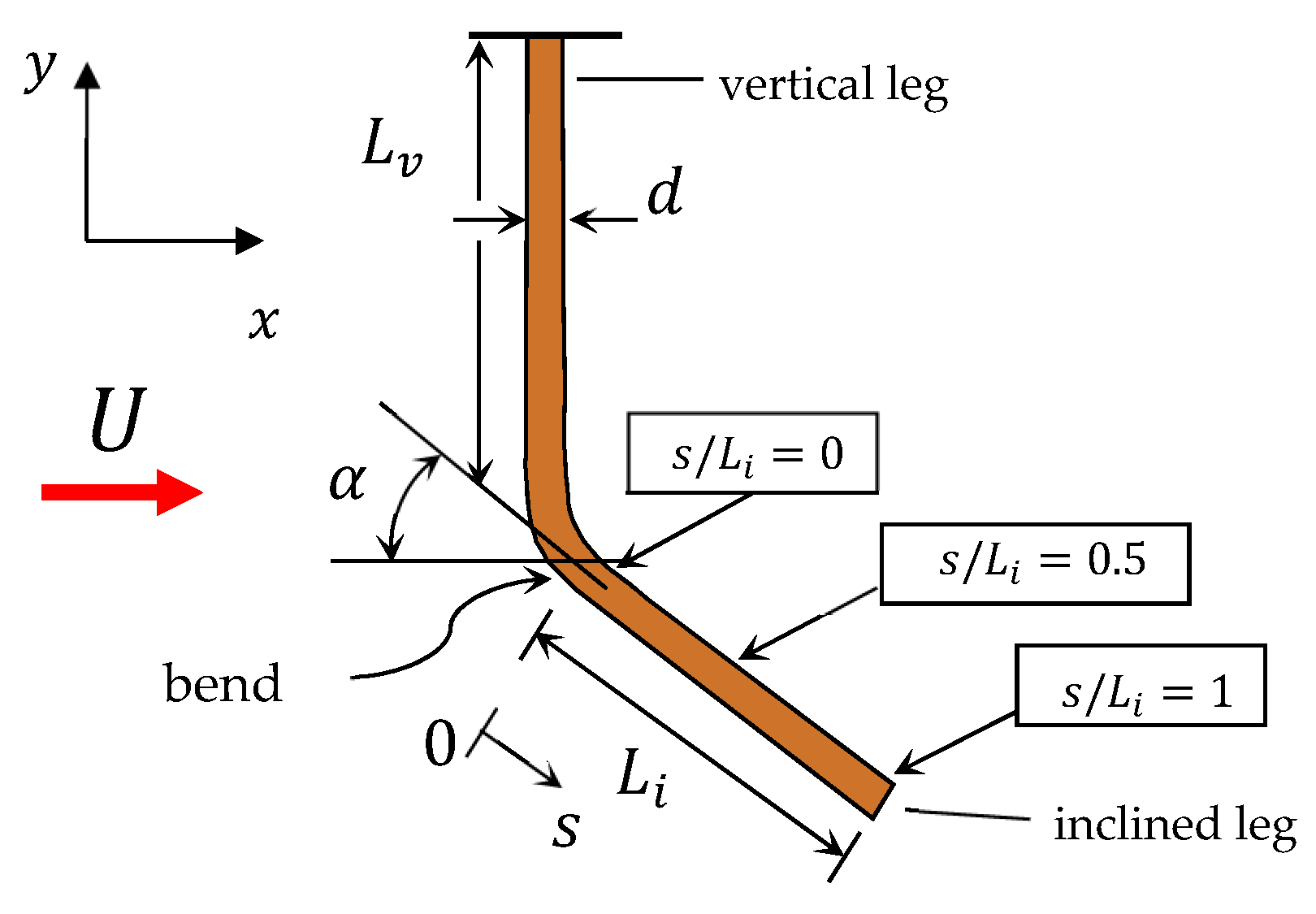
The bent cylinder was realized with copper wire of d = 0.50 ± 0.01 mm diameter and comprised, as schematically shown in Figure 1, a vertical leg and an inclined leg. The length of the vertical leg was L v = 60 ± 0.5 mm, whilst the length of the inclined leg was L i = 20 ± 0.5 mm, thus resulting in aspect ratios of L v / d = 120 and L i / d = 40 , respectively. During the tests, the inclination angle α (measured to within ± 3°) of the inclined leg with respect to the flow was gradually and step-wise varied from 90° (corresponding to cross-flow incidence) down to 15° in steps of 15°, corresponding to six different inclinations: 90°, 75°, 60°, 45°, 30°, and 15°.
Clearly, the 90° inclination corresponds to the limiting case of a cantilever circular cylinder in cross-flow, and was included to verify the asymptotic consistency of the measurements and validate the test apparatus, as described later. The bend between the two cylinder legs was realized to provide a gradual variation between the inclinations of the two legs. In particular, the arc length of the bend increased gradually with decreasing inclination angle, and was approximately 4–5 diameters for the highest inclination (75°) and approximately 15–20 diameters for the lowest inclination (15°). The manufactured surface roughness of the copper wire used to make the bent cylinder was on the order of 2–3 μm (from standard data sheets for copper wires), small enough to neglect its effect on the flow at the Reynolds number values of interest here (50–500). The bent cylinder tested here can therefore be regarded as smooth. Vortex shedding frequencies were measured at three locations along the inclined leg of the bent cylinder, as schematically shown in Figure 1 ( s / L i = 0 ; 0.5 ; 1 ). These locations are indicated in the following using the local position s along the inclined leg, so that s / L i = 0 corresponds to the upstream end of the inclined leg right after the bend, s / L i = 0.5 is the mid-point along the inclined leg, while s / L i = 1 corresponds to the inclined leg free-end.
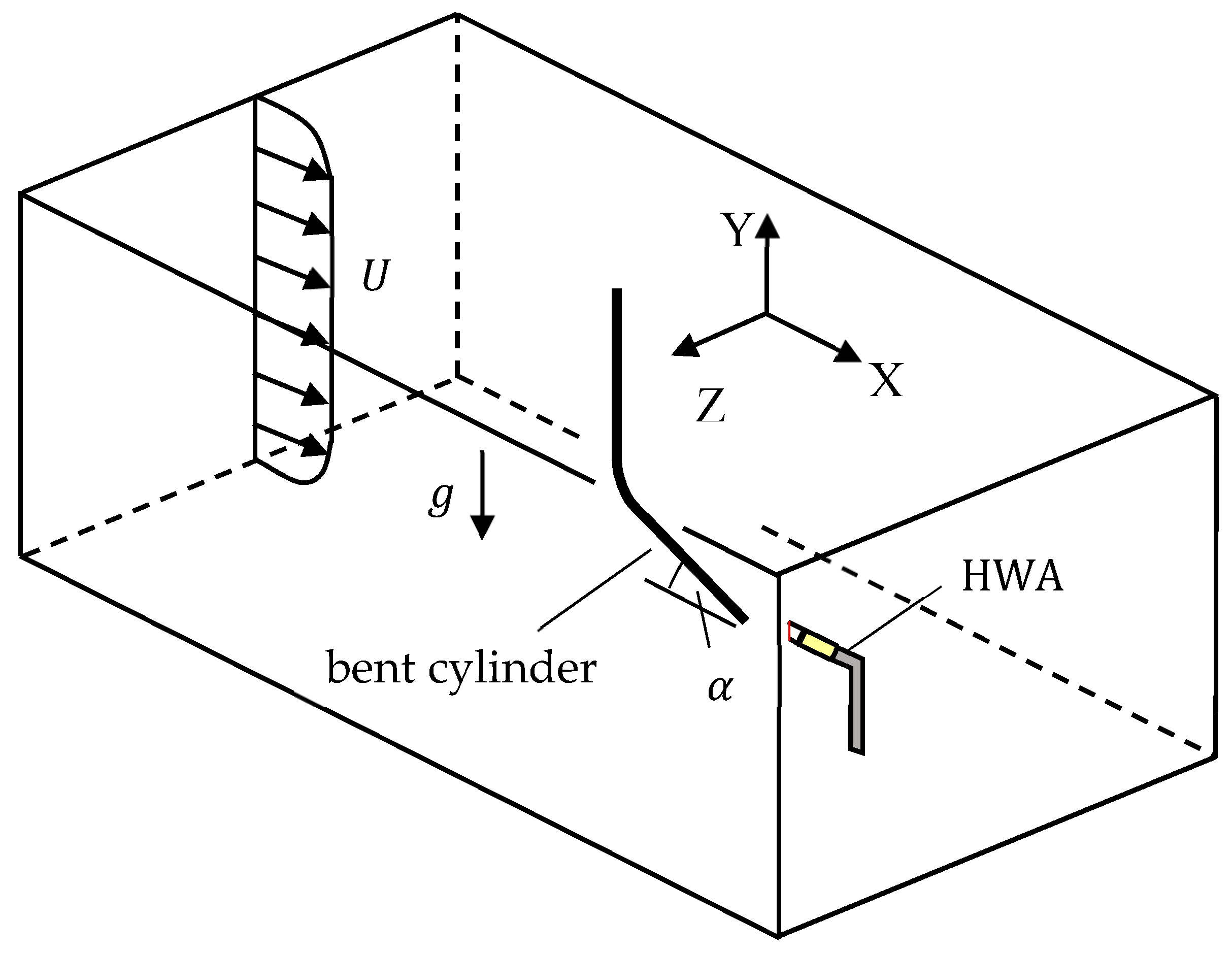
The bent cylinder was tested in a commercial wind tunnel (Armfield Limited, Ringwood, UK (armfieldonline.com)) with an octagonal cross-section and height and width of 350 mm. The blockage ratio associated with the bent cylinder was on the order of 0.1%, so that wind tunnel flow confinement effects can be ignored. As schematically shown in Figure 2, the bent cylinder was placed in a vertical plane with the vertical leg rigidly connected to the ceiling of the wind tunnel. This configuration, which differs from that employed by Ramberg [7], was selected to achieve a better control of the upstream boundary condition acting upon the inclined leg. As evident in Figure 2, the vertical leg is always located upstream of the inclined leg, and therefore determines the upstream boundary condition acting upon the inclined leg. The vertical leg is always at normal incidence with respect to the incoming flow, and is long enough (aspect ratio of 120) to assure that the flow the inclined leg is exposed to at its upstream end corresponds to a fully established (i.e., no wall effects) vortex shedding from a smooth circular cylinder in cross-flow. Vortex shedding frequency measurements carried out behind the inclined leg can therefore be instrumental in assessing to what extent the inclination of the inclined leg affects a fully established cross-flow vortex shedding. In contrast, in the bent cylinder design employed by Ramberg [7], the angle between the cylinder legs was fixed, so that the upstream boundary condition acting upon the cylinder leg where the shedding frequency was being measured varied with the inclination of the leg with respect to the incoming flow. This implies that the upstream boundary condition was not the same at different inclinations, whereas with the present bent cylinder design, the upstream boundary condition is always the same, irrespective of the yaw angle of the inclined leg.

2.2. Flow Measurement and Characterization

Flow velocities were measured with a hot-wire anemometer (Dantec Dynamics, Bristol, UK (www.dantecdynamics.com); probe type 55P15, 5-µm-diameter tungsten wire of 2 mm length), calibrated prior to the tests and operated in constant temperature mode with a sampling frequency of 20 kHz. The hot-wire anemometer was mounted on a 3D traverse system (position accuracy to within ±0.5 mm) and was located downstream of the bent cylinder, as shown schematically in Figure 2. The free-stream flow velocity ranged between 1.5 m/s and 15 m/s, and was measured (to within ± 2% accuracy) with the hot-wire anemometer located in the same vertical plane as the bent cylinder but at a lower vertical elevation. For measuring vortex shedding frequencies, the hot-wire anemometer was located behind the cylinder at the position of maximum velocity fluctuation. This latter was identified empirically during the tests (velocity power spectra were visualized in real-time with LabVIEW 2017), and corresponded to approximately 2.5–5 mm behind the cylinder and about 0.25 mm on the side, as schematically shown in Figure 3.
Power spectra of the velocity time-series were generated with the Welch’s method [27], using MATLAB (version R2015a) built-in functions (200 sample Hamming window length, and 50% overlap). The vortex shedding frequency was identified as the frequency corresponding to the maximum of the dominant peak (when present) in the power spectrum, while its absolute uncertainty was estimated as one-half of the full-width-at-half-maximum of the corresponding peak. Vortex shedding frequencies ranged between 417 Hz and 6.86 kHz, with relative uncertainties of 2–3%.
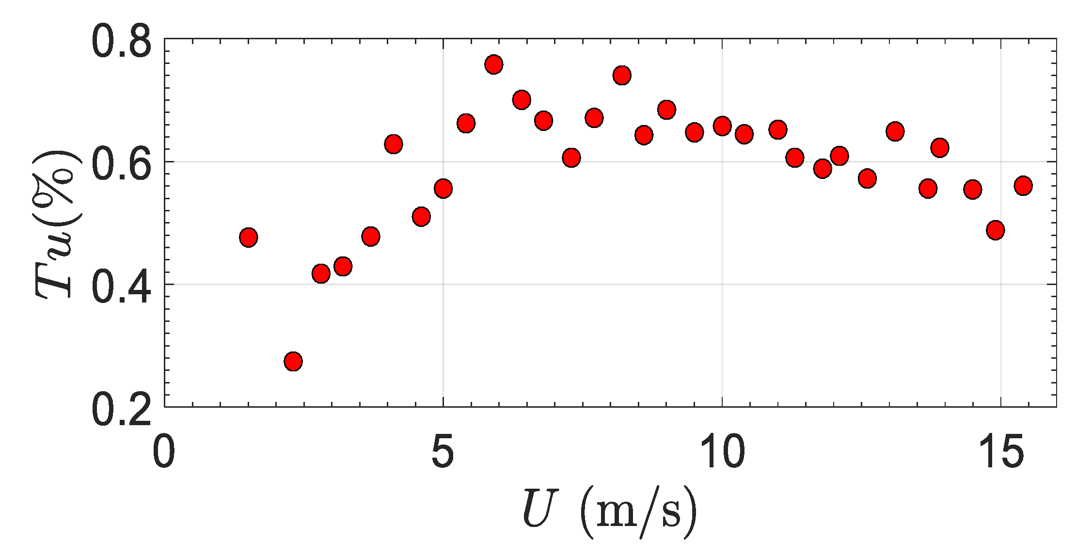
The uniformity of the velocity profile and the extension of the boundary layer inside the wind tunnel were assessed before testing the bent cylinder. The velocity profile (excluding the boundary layer) was uniform to within ±2%, i.e., velocity variations were within the present experimental resolution, while the boundary layer thickness was of about 5 mm at the lowest free-stream flow velocity of interest (1.5 m/s). As shown in Figure 4, the measured turbulence intensity varied with the free-stream flow velocity between 0.28% and 0.78%, corresponding to mild turbulence.
The fluid dynamic load acting on the bent cylinder during the tests was estimated to be in the range of 10–100 μN [28]. Since the focus of the present work was the vortex shedding frequency, and not the fluid dynamic load, this latter was not measured.
The experimental uncertainties, estimated with standard single-sample error propagation [29], are within 5% for the Strouhal number and within 3% for the Reynolds number. Ambient air temperature and pressure during the tests were 293 K and 101.3 kPa.

2.3. Experimental Setup Validation

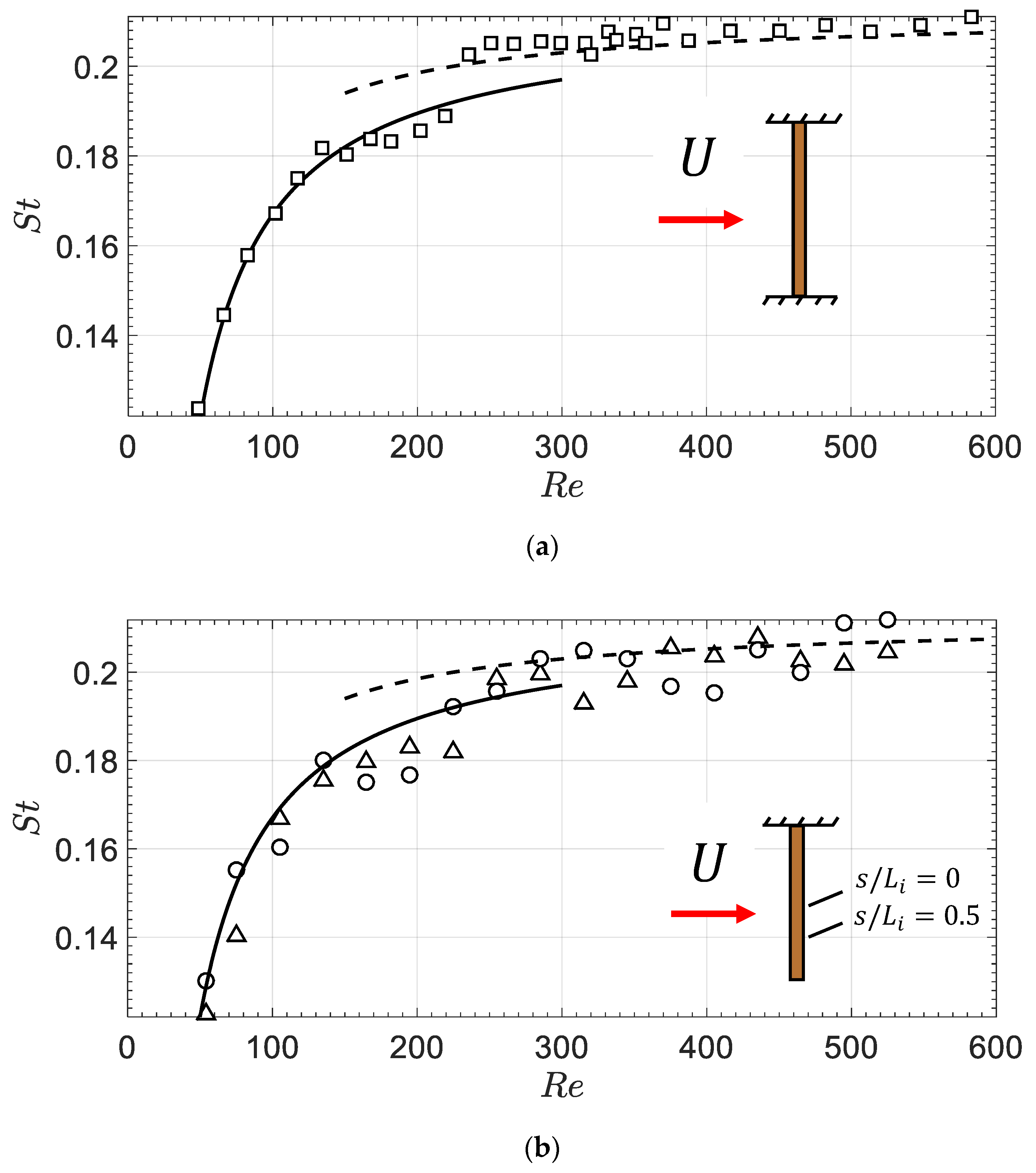
The experimental apparatus was validated with preliminary vortex shedding experiments from a smooth circular cylinder in cross-flow. The cylinder used for the validation was made of the same copper wire (0.5 mm diameter) used to manufacture the bent cylinder, and was stretched vertically and fixed at the walls of the wind tunnel (i.e., a fixed-fixed configuration) as schematically indicated in the insert in Figure 5a. The vortex shedding frequency was measured midway through the cylinder. The measured Strouhal number values are displayed versus the Reynolds number in Figure 5a, together with the predictions of the widely used correlations proposed by Roshko [30] for smooth and stationary circular cylinders in cross-flow:
S t = 0.212 4.5 / R e ; f o r   40 R e < 150 ,
S t = 0.212 2.7 / R e ; f o r   R e > 300 ,
in particular, Equation (3) is applicable when the vortex street is laminar, whereas Equation (4) is valid when the vortex street is turbulent. As is evident in Figure 5a, Equations (3) and (4) have been extended for convenience beyond their respective stated ranges of validity: Equation (3) up to a Reynolds number value of 300, and Equation (4) down to a Reynolds number value of 150. The data points in Figure 5a agree with Equation (3) up to a Reynolds number value of about 230, whilst for higher Reynolds number values the data points agree with Equation (4). The mild discontinuity in the data trend at R e = 230 can therefore be interpreted as a consequence of the laminar to turbulent flow transition in the vortex street. Overall, the agreement between measurements and predictions is good, and this validates the present experimental setup and methodology.
As previously noted, the bent cylinder tests covered six different yaw angles for the inclined leg: 90°, 75°, 60°, 45°, 30°, and 15°. The 90° inclination, in particular, corresponds to the limiting case of a cantilever circular cylinder in cross-flow, and was included to verify the asymptotic consistency of the measurements and further validate the test apparatus. Vortex shedding frequencies measured with the bent cylinder (at the two locations s / L i = 0 ; 0.5 ) in its cross-flow limiting configuration at 90° yaw angle are included in Figure 5b, where the measured Strouhal number is plotted versus the Reynolds number. As can be seen, the agreement between measurements and predictions in Figure 5 (bottom) is good, and this further validates the present experimental setup and methodology.
In the following, on the basis of the results in Figure 5a, cross-flow vortex shedding frequencies will be predicted with the Roshko [30] correlations, and in particular with Equation (3) up to a Reynolds number value of 230, and with Equation (4) for higher Reynolds number values. As is well-known, these correlations are restricted in validity to cross-flow behind smooth and stationary circular cylinders with no end-effects. Comparing the present experimental results for the bent cylinder with the predictions of Equations (3) and (4), therefore, will prove instrumental in assessing the effects of the inclination and end-effects on vortex shedding.

3. Results and Discussion

Representative power spectra measured at two Reynolds number values (75 and 285) and three inclinations (90°, 45°, and 15°) are provided in Figure 6, and include the measurements taken at the three locations along the bent cylinder inclined leg ( s / L i = 0 ; 0.5 ; 1 ). Besides measuring the vortex shedding frequency behind the inclined leg of the bent cylinder, for the sake of verifying the stability and reproducibility of the experimental setup, one additional vortex shedding frequency was measured behind the vertical leg of the bent cylinder. This was always oriented in cross-flow with respect to the flow (this additional measurement was taken midway through the vertical leg, i.e., 30 mm above the bent cylinder bend). This additional measurement is included in the power spectra in Figure 6 and labeled for convenience s / L i = 0.5 . All raw measurements are provided as Supplementary Material.
Following common practice for better visual analysis, the power spectra in Figure 6 have been normalized with respect to the maximum power of the signal. The blue-color vertical plane that can be noticed in the power spectra corresponds to the cross-flow vortex shedding frequency predicted with Equations (3) and (4), and has been included for a qualitative visual comparison.
It is evident, from inspecting Figure 6, that the power spectral peaks measured at the lower Reynolds number ( R e = 75) are very narrow, whereas the peaks measured at the higher Reynolds number ( R e = 285) are broader. On the basis of the previously commented validation results presented in Figure 5a, in the present experimental setup the laminar to turbulent flow transition in the vortex street begins at a Reynolds number of about R e = 230. The vortex street can therefore be expected to be laminar at R e = 75 and turbulent at R e = 285, so that the broadening of the power spectral peaks observed at the higher Reynolds number in Figure 6 can be regarded as the consequence of the turbulence in the vortex street that somewhat degrades the coherence of the vortex shedding [10].
In all cases included in Figure 6, the measurements taken behind the vertical leg ( s / L i = 0.5 ) yield a power spectral peak that is very close to the blue plane, thus indicating vortex shedding at a frequency that compares well (i.e., within a few percent) with cross-flow expectations. This provides further confidence in the presented results.
Surprisingly, the measurements included in Figure 6 taken behind the inclined leg of the bent cylinder yield a power spectral peak that, in most cases, is very close to the blue plane. This indicates that, for the conditions covered in Figure 6, the inclined leg of the bent cylinder is most of the times, shedding vortices at a frequency that is very close (i.e., within a few percent) to the cross-flow frequency for that particular flow velocity. The only exceptions are firstly, a reduction in vortex shedding frequency (of approximately 20% with respect to the corresponding cross-flow frequency) at the free-end of the inclined leg ( s / L i = 1 ) for both Reynolds number values for the 90° inclination, which can be regarded as a free-end effect. Secondly, a suppression of vortex shedding at the free-end of the inclined leg ( s / L i = 1 ) at the lower Reynolds number (75) for the 15° inclination, which again can be regarded as a free-end effect (as a matter of fact, a small peak near the blue plane is still noticeable in the power spectrum, though most of the energy is concentrated at lower frequency). The additional, smaller peak that can be noticed at s / L i = 0 for the lower Reynolds number (75) and 45° inclination is a harmonic of the dominant frequency, because its frequency is twice the dominant frequency.
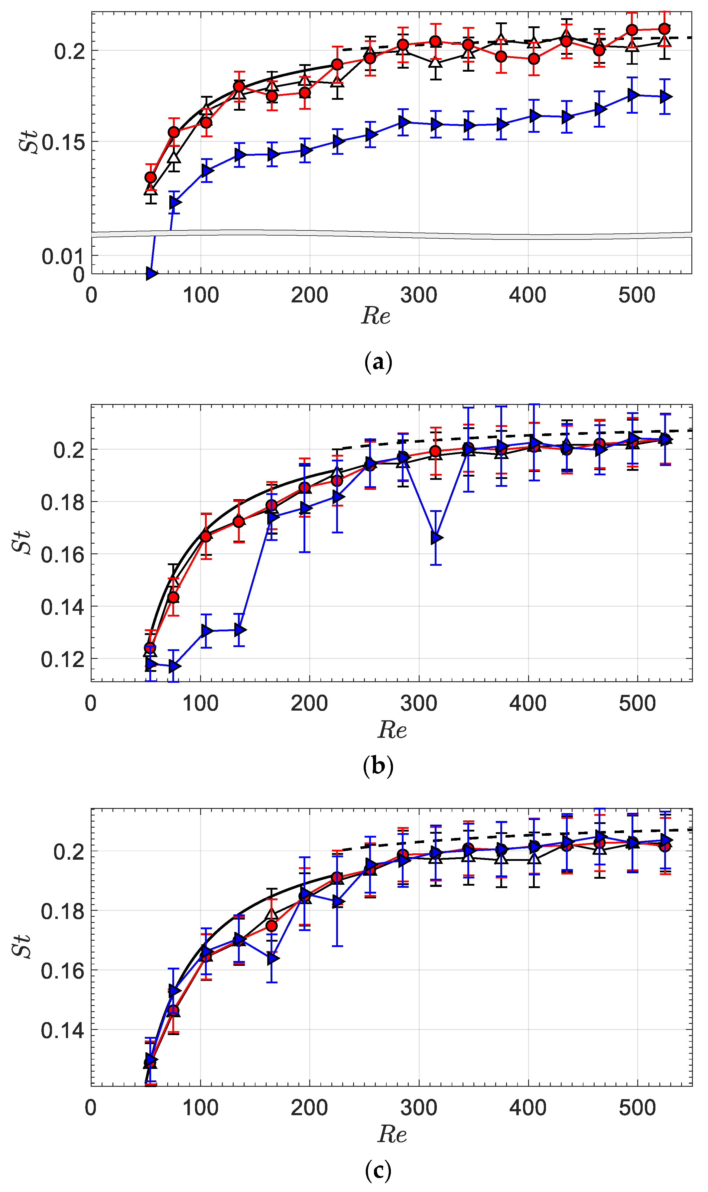
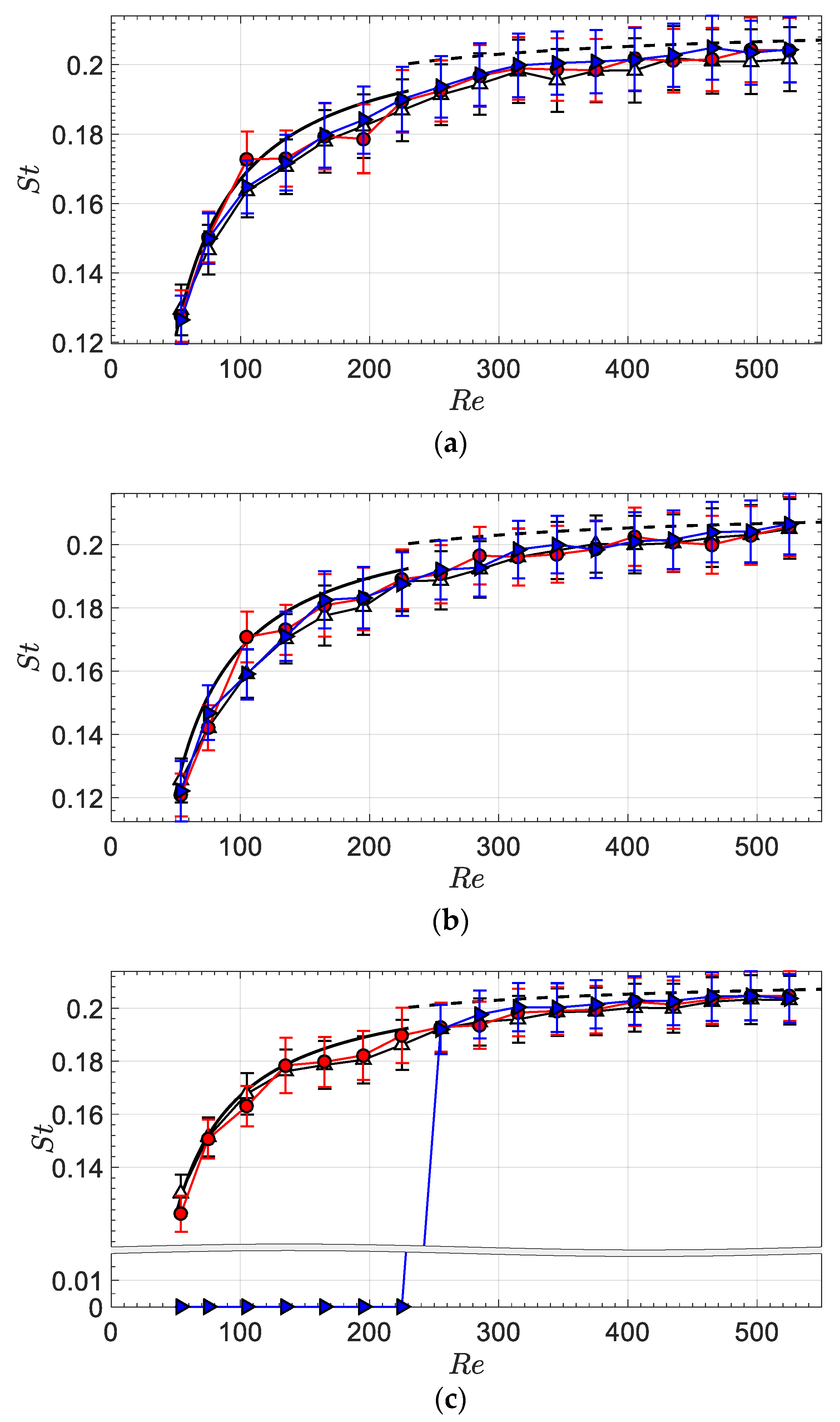
For the conditions covered in Figure 6, therefore, the frequency of vortex shedding behind the inclined leg is for the most part not affected by the yaw angle, and the systematic reduction in shedding frequency normally associated in the literature with inclination effects is therefore not present. The results included in Figure 6 are only a representative subset of the present measurements, so that it is not yet possible to draw any definite conclusions. Analyzing the present databank in terms of power spectra for all Reynolds number values tested (17 values in the range of 50–500) and all inclinations would be impractical. Therefore, the measurements are presented in a condensed and more useful format. The measurements taken at each location along the inclined leg are first presented in contour maps that provide the frequency ratio (i.e., the measured vortex shedding frequency normalized to the corresponding cross-flow vortex shedding frequency, this latter predicted from Equations (3) and (4)), displayed versus the Reynolds number and the inclination. It is noted that a frequency ratio value close to 1 indicates that the measured frequency of vortex shedding is very close to the corresponding cross-flow shedding frequency for that particular flow velocity. One contour map is provided, in Figure 7, for each location along the inclined leg of the bent cylinder ( s / L i = 0 ; 0.5 ; 1 ). In addition, the data are also provided, in Figure 8 and Figure 9, in the more familiar form of Strouhal-Reynolds numbers plot. There is one such plot for each inclination (90°, 75°, 60°, 45°, 30°, and 15°). It is noted that, for the convenience of the reader, the measurements taken at 90° inclination previously presented in Figure 5b are also included in Figure 8 and Figure 9. The contour maps provide a clear visual representation of the vortex shedding and its dependence on the Reynolds number and inclination, allowing extrapolating the results to Reynolds number values and inclinations intermediate between those tested. The Strouhal-Reynolds number plots, on the other hand, provide the data in the form that is most frequently encountered in the literature, and allow a direct quantitative comparison of the present data with the cross-flow vortex shedding prediction methods in Equations (3) and (4).
The results in Figure 7, Figure 8 and Figure 9 confirm and generalize the observations based on the power spectral densities presented in Figure 6 and previously discussed. That is, most of the times, the inclined leg of the bent cylinder sheds vortices at a frequency that is very close (within a few percent) to the cross-flow frequency for that particular flow velocity. The only exceptions are noticeable at the inclined leg free-end ( s / L i = 1 ) for certain inclinations and Reynolds number values, and can therefore be regarded as free-end effects. In particular:
  • For the limiting inclination of 90° (Figure 8a), vortex shedding frequencies at the inclined leg free-end are reduced with respect to cross-flow predictions by about 15–20% at all Reynolds number values tested, and vortex shedding is suppressed altogether for the lowest Reynolds number tested (50). Note that the suppression of vortex shedding is here indicated with a null value of the vortex shedding frequency and Strouhal number.
  • For the inclination of 75° (Figure 8b), vortex shedding frequencies at the inclined leg free-end are reduced with respect to cross-flow predictions by about 20–25% in the Reynolds number range of 75–140, and by about 20% at a Reynolds number of 320. At the inclination of 75°, the vortex shedding frequencies measured at the inclined leg free-end for Reynolds numbers within 190–230 and within 350–410 agree well with the cross-flow predictions, though the respective error bars are slightly larger, indicating that the vortex shedding is slightly less coherent. As previously discussed, the absolute uncertainty of the vortex shedding frequency is here estimated as one-half of the full-width-at-half-maximum of the corresponding peak in the power spectrum. An increase in the relative uncertainty of the Strouhal number in Figure 8, therefore, originates from the broadening of the dominant peak in the power spectrum, which in turn indicates that vortex shedding is losing coherence [10].
  • Finally, for the inclination of 15° (Figure 9c), vortex shedding is suppressed altogether at the inclined leg free-end for Reynolds numbers below 225.
For the operating conditions covered in the present study, and with the exception of the free-end effects just discussed, the frequency of vortex shedding behind the inclined leg of the bent cylinder is not affected by the yaw angle. Deviations with respect to the corresponding cross-flow vortex shedding frequency are in fact on the order of a few percent, which is comparable with the present measuring error. This is noteworthy and indicates that, with the bent cylinder considered here, inclination effects are not present. The present results are in stark contrast with the available literature on vortex shedding behind inclined cylinders, where a systematic reduction in vortex shedding frequency is normally associated with inclination effects. As previously discussed, the flow field that develops around a cylinder with arbitrary inclination with respect to the incoming flow is three-dimensional, and includes an axial-flow component resembling a boundary layer flow that gradually develops along the cylinder. This, in turn, makes the flow field around the inclined cylinder strongly dependent upon the upstream boundary condition, whose effect is not localized but rather transported along the cylinder by the axial boundary layer flow. With the bent cylinder design proposed here, the upstream boundary condition acting upon the inclined leg is imposed by the vertical leg, and corresponds to a fully-established cross-flow vortex shedding. The absence of inclination effects on vortex shedding behind the inclined leg, therefore, suggests that the flow that develops around the inclined leg of the present bent cylinder is entirely controlled by the upstream boundary condition.
As previously noted, the only experiment on vortex shedding from bent cylinders currently available is documented in the study by Ramberg [7], who tested a cylinder bent into a V-shape with a fixed aperture of 120° between the two legs. A disadvantage of adopting a bent cylinder design with a fixed aperture between the cylinder legs is that the upstream boundary condition acting upon the cylinder leg where the shedding frequency is measured varies with the inclination of the leg with respect to the incoming flow, and is therefore not the same at different yaw angles. The bent cylinder tested here, on the other hand, had different apertures between the legs, so that one leg was always at normal incidence with respect to the free-stream. The upstream boundary condition was therefore always the same, irrespective of the yaw angle of the inclined leg. Despite this improvement in the present bent cylinder design, the present results can be compared with the data from Ramberg [7], who measured the vortex shedding frequency behind one leg of his bent cylinder (about midway along the leg) at two Reynolds number values (160 and 460) for inclinations between 90° and 30°. Even though the tests by Ramberg [7] with the bent cylinder were rather limited in scope (only 26 data points in total), the measurements were consistent (to within 15%) with cross-flow vortex shedding, indicating no major inclination effects on the vortex shedding frequency. The present results, therefore, confirm the significance of the bent cylinder configuration originally proposed by Ramberg [7], and corroborate his observations to wider scope (the present databank includes 306 data points in total), tighter tolerance (on account of the improved bent cylinder design adopted here with a better control over the upstream boundary condition, the present data agree with cross-flow predictions to within a few percent, excluding free-end effects), and wider Reynolds number (50–500) and inclination angle (90°–15°) ranges.
Within the limits of the present study, the axial boundary layer flow seems effective at transporting the upstream boundary condition along the inclined leg of the bent cylinder, but does not seem to otherwise affect the flow. It is worth noting that this would no longer be necessarily the case for a bent cylinder with a longer inclined leg. If the inclined leg was longer, in fact, the axial boundary layer flow would have more time to develop and might even separate, and could therefore more profoundly affect the flow. This clearly motivates further work into vortex shedding behind bent cylinders, focusing in particular on bent cylinders with a longer inclined leg. Analyzing the evolution of the axial boundary layer flow would necessarily require some sort of flow visualization, such as a PIV (Particle Image Velocimetry). Depending on the size of the bent cylinder and on the operating conditions, a high-frequency micro-PIV might be required (the present bent cylinder was 0.5 mm in diameter, and vortex shedding frequencies were as large as 6.86 kHz). High-fidelity CFD (Computational Fluid Dynamics) simulations might be a viable and effective alternative to an experimental flow visualization.
4. Conclusions

The vortex shedding frequency behind a smooth and stationary bent cylinder was experimentally investigated in a wind tunnel setup using hot-wire anemometry. The bent cylinder design comprised two legs. One leg was always vertically oriented at normal incidence with respect to the free-stream flow, whilst the inclination of the other leg was varied during the tests between 90° (corresponding to cross-flow incidence) and 15° to assess the effect of the inclination on the vortex shedding frequency. The Reynolds number was varied between 50 and 500 which is a range of interest for flow sensing, flow control, and energy harvesting applications where slender flexible structures reconfigure or bend when exposed to fluid flow. During the tests, the bent cylinder was oriented in the wind tunnel with the vertical leg located upstream and the inclined leg downstream. This way, the boundary condition acting upon the upstream free-end of the inclined leg was determined by vertical leg, and corresponded to cross-flow vortex shedding regardless of the yaw angle of the inclined leg. This bent cylinder configuration, which differs from and improves upon those previously considered, was explicitly conceived to provide a fine control on the upstream boundary condition acting upon the inclined leg, which profoundly affects the flow. The flow around the bent cylinder inclined leg, in fact, is three-dimensional and includes an axial boundary layer flow component that transports the upstream boundary condition along the inclined leg, so that the effect of the upstream boundary condition is not localized as happens in the cross-flow configuration. With the exception of free-end effects, only noticeable for certain inclinations and Reynolds number values, the frequency of vortex shedding behind the inclined leg of the bent cylinder was consistent (within a few percent) with the cross-flow vortex shedding frequency at the same flow velocity, and was therefore not affected by the yaw angle. The present results corroborate and significantly extend the limited observations on bent cylinders available in the literature, further highlighting the importance of the upstream boundary condition on the vortex shedding process with inclined cylinders. Future work will look into vortex shedding behind bent cylinders with longer inclined legs, with a view at resolving the axial boundary layer flow along the inclined leg of the bent cylinder and investigate its effect on the vortex shedding.

Supplementary Materials

The following are available online at https://www.mdpi.com/2311-5521/4/2/100/s1, The raw data (wind speeds, vortex shedding frequencies, width of vortex shedding peaks in PSDs, inclination angle, axial position) are available online in the file Raw_data.xlsx.

Author Contributions

Conceptualization, J.S.-L. and A.C.; experiments, J.S.-L.; analysis, J.S.-L. and A.C.; original draft preparation, J.S.-L.; writing—review and editing, A.C.

Funding

This research was partially funded by Secretaría Nacional de Educación Superior, Ciencia, Tecnología e Innovación (SENESCYT) of Ecuador, through the scholarship Convocatoria Abierta 2012-I.

Acknowledgments

Andrew Kennaugh from the School of Mechanical, Aerospace and Civil Engineering of the University of Manchester (UK) is gratefully acknowledged for his technical support.

Conflicts of Interest

The authors declare no conflicts of interest.

References

  1. Blevins, R.D. Flow-Induced Vibration, 2nd ed.; Krieger Publishing Company: Malabar, FL, USA, 2001. [Google Scholar]
  2. Naudascher, E.; Rockwell, D. Flow-Induced Vibrations: An Engineering Guide; Dover Publications, Inc.: Mineola, NY, USA, 1994. [Google Scholar]
  3. Paidoussis, M.P. Fluid-Structure Interactions: Slender Structures and Axial Flow, 2nd ed.; Academic Press: Waltham, MA, USA, 2014; Volume 1. [Google Scholar]
  4. Hanson, A.R. Vortex shedding from yawed cylinders. AIAA J. 1966, 4, 738–740. [Google Scholar]
  5. Van Atta, C.W. Experiments on vortex shedding from yawed circular cylinders. AIAA J. 1968, 6, 931–933. [Google Scholar]
  6. Thomson, K.D.; Morrison, D.F. The spacing, position and strength of vortices in the wake of slender cylindrical bodies at large incidence. J. Fluid Mech. 1971, 50, 751–783. [Google Scholar] [CrossRef]
  7. Ramberg, S.E. The effects of yaw and finite length upon the vortex wakes of stationary and vibrating circular cylinders. J. Fluid Mech. 1983, 128, 81–107. [Google Scholar] [CrossRef]
  8. Bull, M.K.; Dekkers, W.A. Vortex shedding from long slender cylinders in near-axial flow. Phys. Fluids A Fluid Dyn. 1993, 5, 3296–3298. [Google Scholar] [CrossRef]
  9. Lucor, D.; Karniadakis, G.E. Effects of oblique inflow in vortex-induced vibrations. Flow Turbul. Combust. 2003, 71, 375–389. [Google Scholar] [CrossRef]
  10. Snarski, S.R. Flow over yawed circular cylinders: Wall pressure spectra and flow regimes. Phys. Fluids 2004, 16, 344–359. [Google Scholar] [CrossRef]
  11. Trim, A.D.; Braaten, H.; Lie, H.; Tognarelli, M.A. Experimental investigation of vortex-induced vibration of long marine risers. J. Fluids Struct. 2005, 21, 335–361. [Google Scholar] [CrossRef]
  12. Yeo, D.; Jones, N.P. Investigation on 3-D characteristics of flow around a yawed and inclined circular cylinder. J. Wind Eng. Ind. Aerodyn. 2008, 96, 1947–1960. [Google Scholar] [CrossRef]
  13. Zuo, D.; Jones, N.P. Wind tunnel testing of yawed and inclined circular cylinders in the context of field observations of stay-cable vibrations. J. Wind Eng. Ind. Aerodyn. 2009, 97, 219–227. [Google Scholar] [CrossRef]
  14. Song, J.N.; Lu, L.; Teng, B.; Park, H.I.; Tang, G.Q.; Wu, H. Laboratory tests of vortex-induced vibrations of a long flexible riser pipe subjected to uniform flow. Ocean Eng. 2011, 38, 1308–1322. [Google Scholar] [CrossRef]
  15. Jain, A.; Modarres-Sadeghi, Y. Vortex-induced vibrations of a flexibly-mounted inclined cylinder. J. Fluids Struct. 2013, 43, 28–40. [Google Scholar]
  16. Bourguet, R.; Triantafyllou, M.S. Vortex-induced vibrations of a flexible cylinder at large inclination angle. Philos. Trans. A Math. Phys. Eng. Sci. 2015, 373, 20140108. [Google Scholar] [CrossRef] [PubMed]
  17. Bourguet, R.; Karniadakis, G.E.; Triantafyllou, M.S. On the validity of the independence principle applied to the vortex-induced vibrations of a flexible cylinder inclined at 60°. J. Fluids Struct. 2015, 53, 58–69. [Google Scholar] [CrossRef]
  18. Hoang, M.C.; Laneville, A.; Légeron, F. Experimental study on aerodynamic coefficients of yawed cylinders. J. Fluids Struct. 2015, 54, 597–611. [Google Scholar]
  19. Leclercq, T.; de Langre, E. Vortex-induced vibrations of cylinders bent by the flow. J. Fluids Struct. 2018, 80, 77–93. [Google Scholar] [CrossRef]
  20. Kottapalli, A.G.P.; Bora, M.; Sengupta, D.; Miao, J.; Triantafyllou, M.S. Hydrogel-CNT Biomimetic Cilia for Flow Sensing. In Proceedings of the IEEE Sensors 2018, New Delhi, India, 28–31 October 2018. [Google Scholar]
  21. Beem, H.; Hildner, M.; Triantafyllou, M.S. Calibration and validation of a harbor seal whisker-inspired flow sensor. Smart Mater. Struct. 2012, 22, 014012. [Google Scholar]
  22. Silva-Leon, J.; Cioncolini, A.; Filippone, A.; Domingos, M. Flow-induced motions of flexible filaments hanging in cross-flow. Exp. Therm. Fluid Sci. 2018, 97, 254–269. [Google Scholar] [Green Version]
  23. Silva-Leon, J.; Cioncolini, A. Modulation of flexible filament dynamics due to attachment angle relative to the flow. Exp. Therm. Fluid Sci. 2019, 102, 232–244. [Google Scholar] [CrossRef]
  24. Pinelli, A.; Omidyeganeh, M.; Brücker, C.; Revell, A.; Sarkar, A.; Alinovi, E. The PELskin project: Part IV—control of bluff body wakes using hairy filaments. Meccanica 2017, 52, 1503–1514. [Google Scholar]
  25. Antoine, G.O.; de Langre, E.; Michelin, S. Optimal energy harvesting from vortex-induced vibrations of cables. Proc. R. Soc. A 2016, 472, 20160583. [Google Scholar] [CrossRef] [PubMed]
  26. Grouthier, C.; Michelin, S.; Bourguet, R.; Modarres-Sadeghi, Y.; De Langre, E. On the efficiency of energy harvesting using vortex-induced vibrations of cables. J. Fluids Struct. 2014, 49, 427–440. [Google Scholar] [CrossRef] [Green Version]
  27. Welch, P.D. The use of Fast Fourier Transform for the estimation of power spectra: A method based on time averaging over short, modified periodograms. IEEE Trans. Audio Electroacoust. 1967, 2, 70–73. [Google Scholar] [CrossRef]
  28. Silva-Leon, J.; Cioncolini, A.; Filippone, A. Determination of the normal fluid load on inclined cylinders from optical measurements of the reconfiguration of flexible filaments in flow. J. Fluids Struct. 2018, 76, 488–505. [Google Scholar] [CrossRef] [Green Version]
  29. Taylor, J.R. An Introduction to Error Analysis, 2nd ed.; University Science Books: Sausalito, CA, USA, 1997. [Google Scholar]
  30. Roshko, A. On the Drag and Shedding Frequency of Two-Dimensional Bluff Bodies; NACA Technical Note 3169; National Advisory Committee for Aeronautics: Washington, DC, USA, 1954; pp. 1–30. [Google Scholar]
Figure 1. Schematic representation of the bent cylinder design adopted in the present study.
Fluids 04 00100 g001
Figure 2. Schematic representation of the experimental wind tunnel setup.
Fluids 04 00100 g002
Figure 3. Schematic representation of the location of the hot-wire anemometer (HWA) relative to the cylinder during vortex shedding frequency measurements.
Fluids 04 00100 g003
Figure 4. Turbulence intensity of the free-stream flow in the wind tunnel as a function of the wind speed.
Fluids 04 00100 g004
Figure 5. Experimental setup validation: Strouhal number versus Reynolds number for the smooth circular cylinder in cross-flow: fixed-fixed cylinder (a), and bent cylinder in its asymptotic limiting configuration at 90° yaw angle (b). Symbols: s / L i = 0   ( ) ,   0.5 ( ) . Continuous line: Equation (3); Dashed line: Equation (4).
Fluids 04 00100 g005
Figure 6. Normalized power spectral densities (PSD) measured at two Reynolds number values ( R e = 75: (a,c,e); R e = 285: (b,d,f)) and three inclination angles (90°: (a,b); 45°: (c,d), 15°: (e,f)).
Fluids 04 00100 g006
Figure 7. Contour maps of frequency ratio versus the inclination angle and Reynolds number at different locations along the bent cylinder inclined leg: s / L i = 0 (a), s / L i = 0.5 (b), and s / L i = 1 (c).
Fluids 04 00100 g007
Figure 8. Strouhal number versus Reynolds number along the bent cylinder inclined leg at different inclinations: 90° (a); 75° (b); 60° (c). Symbols: s / L i = 0   ( ) , 0.5 ( ) ,   1 ( ) . Continuous line: Equation (3); Dashed line: Equation (4).
Fluids 04 00100 g008
Figure 9. Strouhal number versus Reynolds number along the bent cylinder inclined leg at different inclinations: 45° (a); 30° (b); 15° (c). Symbols: s / L i = 0   ( ) , 0.5 ( ) ,   1 ( ) . Continuous line: Equation (3); Dashed line: Equation (4).
Fluids 04 00100 g009