Article

Time-Dependent Shear Stress Distributions during Extended Flow Perfusion Culture of Bone Tissue Engineered Constructs

1
Stephenson School of Biomedical Engineering, University of Oklahoma, Norman, OK 73019, USA
2
Otto H. York Department of Chemical and Materials Engineering, New Jersey Institute of Technology, Newark, NJ 07102, USA
*
Author to whom correspondence should be addressed.
Fluids 2018, 3(2), 25; https://doi.org/10.3390/fluids3020025
Submission received: 9 January 2018 / Revised: 23 March 2018 / Accepted: 29 March 2018 / Published: 3 April 2018
(This article belongs to the Special Issue Flow and Heat or Mass Transfer in the Chemical Process Industry)

Abstract

:
Flow perfusion bioreactors have been extensively investigated as a promising culture method for bone tissue engineering, due to improved nutrient delivery and shear force-mediated osteoblastic differentiation. However, a major drawback impeding the transition to clinically-relevant tissue regeneration is the inability to non-destructively monitor constructs during culture. To alleviate this shortcoming, we investigated the distribution of fluid shear forces in scaffolds cultured in flow perfusion bioreactors using computational fluid dynamic techniques, analyzed the effects of scaffold architecture on the shear forces and monitored tissue mineralization throughout the culture period using microcomputed tomography. For this study, we dynamically seeded one million adult rat mesenchymal stem cells (MSCs) on 85% porous poly(l-lactic acid) (PLLA) polymeric spunbonded scaffolds. After taking intermittent samples over 16 days, the constructs were imaged and reconstructed using microcomputed tomography. Fluid dynamic simulations were performed using a custom in-house lattice Boltzmann program. By taking samples at different time points during culture, we are able to monitor the mineralization and resulting changes in flow-induced shear distributions in the porous scaffolds as the constructs mature into bone tissue engineered constructs, which has not been investigated previously in the literature. From the work conducted in this study, we proved that the average shear stress per construct consistently increases as a function of culture time, resulting in an increase at Day 16 of 113%.

1. Introduction

Every year in the United States, there are more than 500,000 bone graft surgeries [1]. In most cases, bone will regenerate after fracture with minimal complications; however, when there is a critically-sized defect or fracture healing is impaired, bone grafts must be used in order to regain proper bone function. Furthermore, bone diseases such as osteoporosis, infection, skeletal defects and bone cancer may also cause a need for bone grafts. Bone tissue engineering is a possible solution to the problems plaguing the current bone graft therapies. Because tissue engineered bone would be made using the patient’s own cells, immune rejection would be eliminated. For this to work, four components are needed for tissue growth: cells that can be differentiated into bone cells, osteoconductive scaffolds acting as a matrix while the tissue grows, growth factors and other chemical stimulation and mechanical stimulation to encourage osteogenic differentiation. Mechanical stimulation, in particular, is implemented through the use of bioreactors.
Previous studies have given the indication that the shear stresses bone cells experience inside the body are between 8 and 30 dynes/cm 2 [2]. In vitro culture studies combined with computational fluid dynamic simulation results have shown that shear stresses below 15 dynes/cm 2 are conducive to increased matrix production and osteoblastic differentiation. However, if the shear rates are too high, detachment or cell death can occur [3]. In addition, whenever inhomogeneous cell seeding distributions occur, especially in the case of cell aggregates, even modest shear rates that are otherwise beneficial may result in cell detachment [4,5,6,7]. Due to this, it is important to properly model and evaluate the flow profile inside cell-seeded scaffolds [8,9,10,11]. Ideally, the localized shear rates should be anticipated in order to give proper fluid control. However, the largest barrier to this goal is the continual deposition of mineralized tissue during the culture period. After the stem cells differentiate into mature osteoblasts, both soft and hard extracellular matrices grow into the pores of the construct. This effectively alters the flow field, due to the porosity of the scaffold decreasing, and renders simulations performed on empty scaffolds invalid after the start of culture.
To combat this issue, we aimed to evaluate the localized fluid shear distributions throughout the culture period, giving an indication of the effects of tissue growth on the flow-induced stress fields, which has been extensively investigated in the literature [12,13,14,15,16]. Using spunbonded poly(l-lactic acid) scaffolds and a custom flow perfusion bioreactor, we cultured rat mesenchymal stem cells for 16 days under shear-induced differentiation flow ranges. The resulting constructs were imaged utilizing microcomputed tomography ( μ CT), segmented and reconstructed following previously published techniques [2,17,18]. This flow path allows for subsequent computational fluid dynamic (CFD) simulations on the cultured constructs.
In this manuscript, we hypothesized that the levels of fluid shear present at the walls of a scaffold, where the cells are located, will increase as a function of culture time. Previous studies have assumed that (1) the shear field predicted using a non-cultured scaffold is representative of cultured constructs and (2) that the average wall shear experienced by the cells is constant throughout a culture period [18,19]. The intention of this study is to use CFD simulations in conjunction with microcomputed tomography of mature constructs and biochemical assays to bring to light the relationship between the localized shear field and culture time, which would give researchers the ability to predict the time-dependent shear distribution in conjunction with the growing extracellular matrix within three dimensional scaffolds exposed to flow perfusion.

2. Results

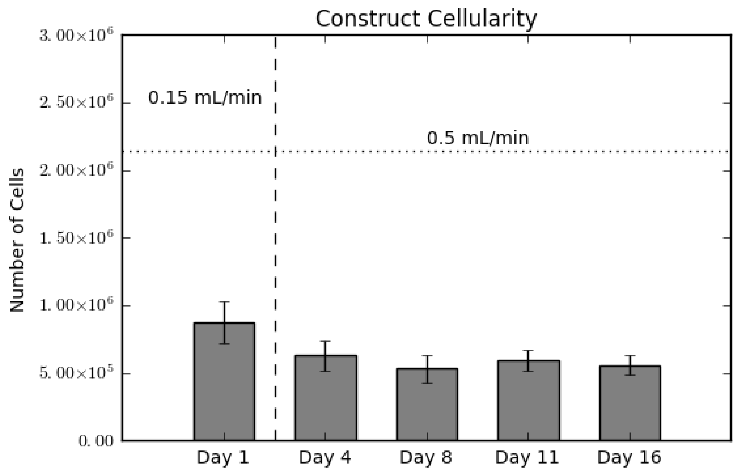
2.1. Construct Cellularity

In order to validate the presence of cells in the constructs, we conducted a destructive dsDNA quantification assay. As shown in Figure 1, there is a slight decrease in scaffold cellularity between Day 1 and Day 4, and a statistically steady cellularity through the end of culture. The vertical dotted line between Day 1 and Day 4 indicates the switch in flow rate from 0.15 mL/min–0.5 mL/min. Hence the decrease between these two days represents a loss of cells either due to cell detachment or as a result of cell death [20,21]. This loss is a common occurrence, as MSCs display weak adherence to poly(l-lactic acid) (PLLA). The horizontal dashed line represents the amount of cells initially seeded on the constructs. The ratio between this line and Day 1 is known as the seeding efficiency, which in this case is 40%.

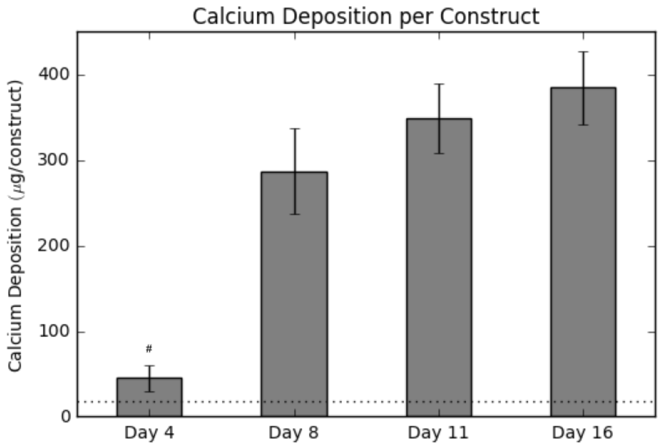
2.2. Calcium Deposition

Calcium deposition was measured using a calcium assay at each sacrificial time point, with results shown in Figure 2. As seen in the graph, there is a sharp increase in calcium deposition around Day 8. In conjunction with the calcium assay, we rendered a 3D representation of the constructs (Figure 3 and Figure 4), which were imaged using μ CT. Extensive mineralized tissue can be seen in samples sacrificed after Day 8, while samples prior to that time displayed only minor mineralized tissue. It can be noted that the largest standard deviation in mineralization was observed in samples sacrificed on Day 8, a time point that matches the onset of extensive mineralization (Figure 3). A similar spike in mineralized tissue can be seen around Day 11.

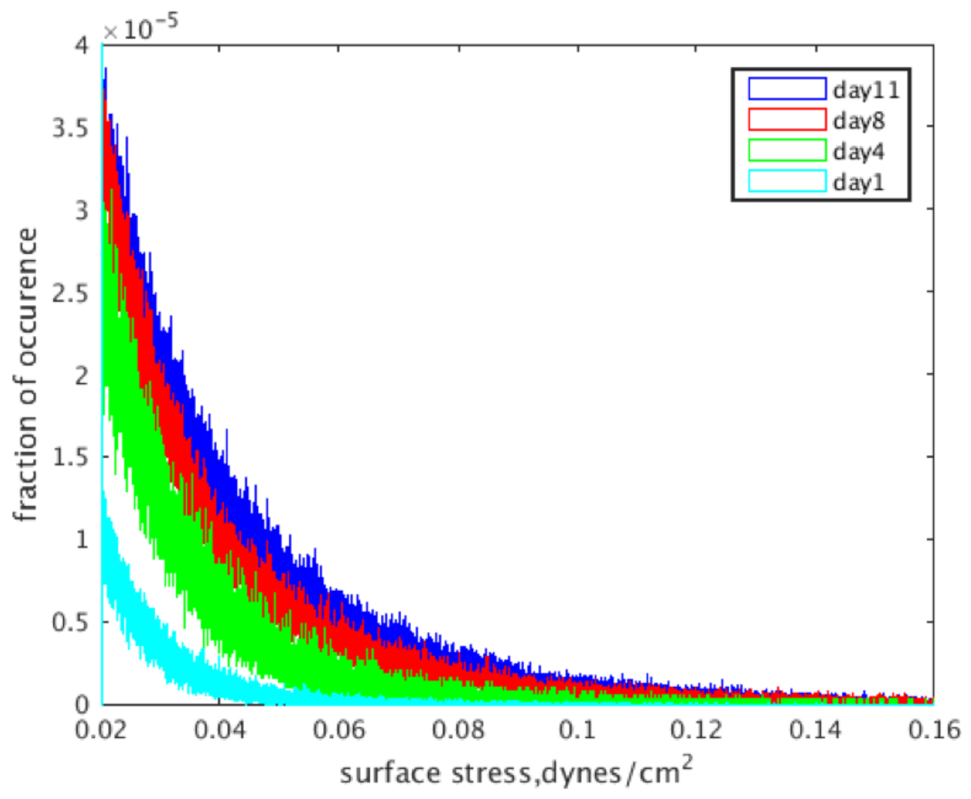
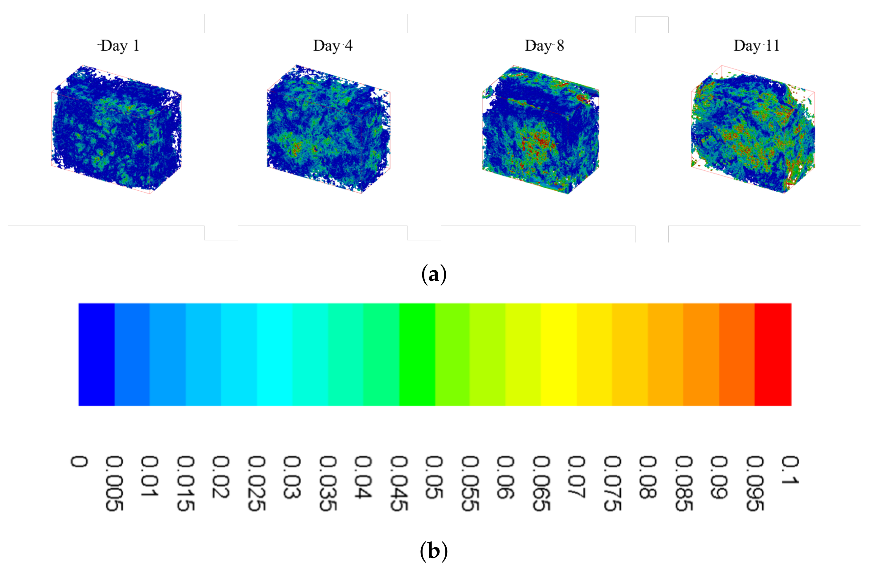
2.3. Shear Stress Distributions over Time

The localized fluid shear stress distributions for the reconstructions at each intermittent time point are shown in Figure 5, where light blue is Day 1, green is Day 4, red is Day 8 and dark blue is Day 11. The data presented show a pronounced increase in shear stress levels with an increase in culture time, which is evident by the rightwards shift in distributions shown in the graph.

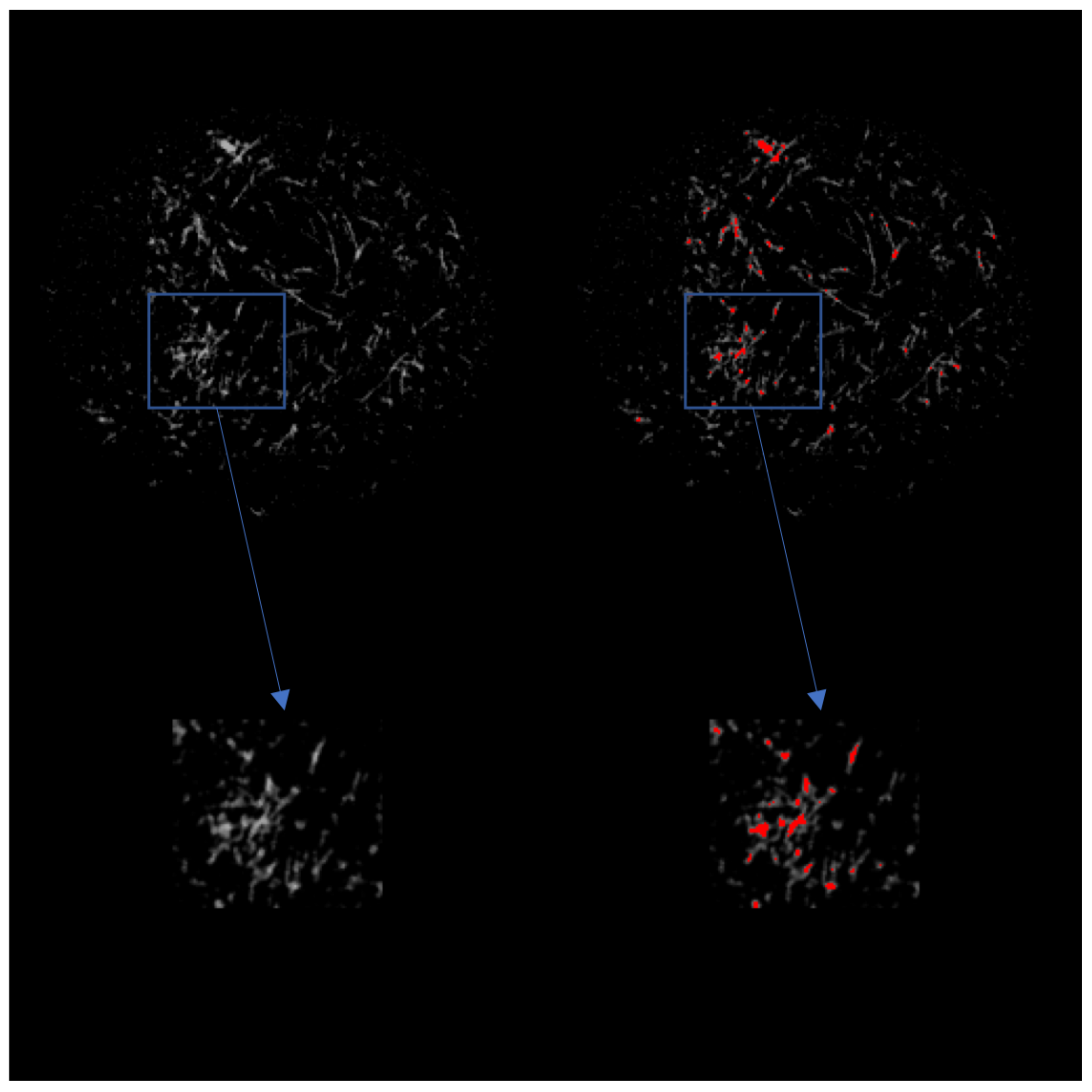
2.4. Effects of Calcium Deposition on Localized Shear Fields

Figure 6 shows isometric sections of reconstructed scaffolds, with wall shear stress heat maps overlaid on top. It is evident that there are higher levels of shear stress present during the later time points, which is supported by the distributions shown in Figure 5. As pore size decreases, bottlenecks occur resulting in increased fluid velocity and, subsequently, increased shear stress (yellow and red colors in the figure). Furthermore, these increased levels of shear stress are more widely distributed as culture time increases.

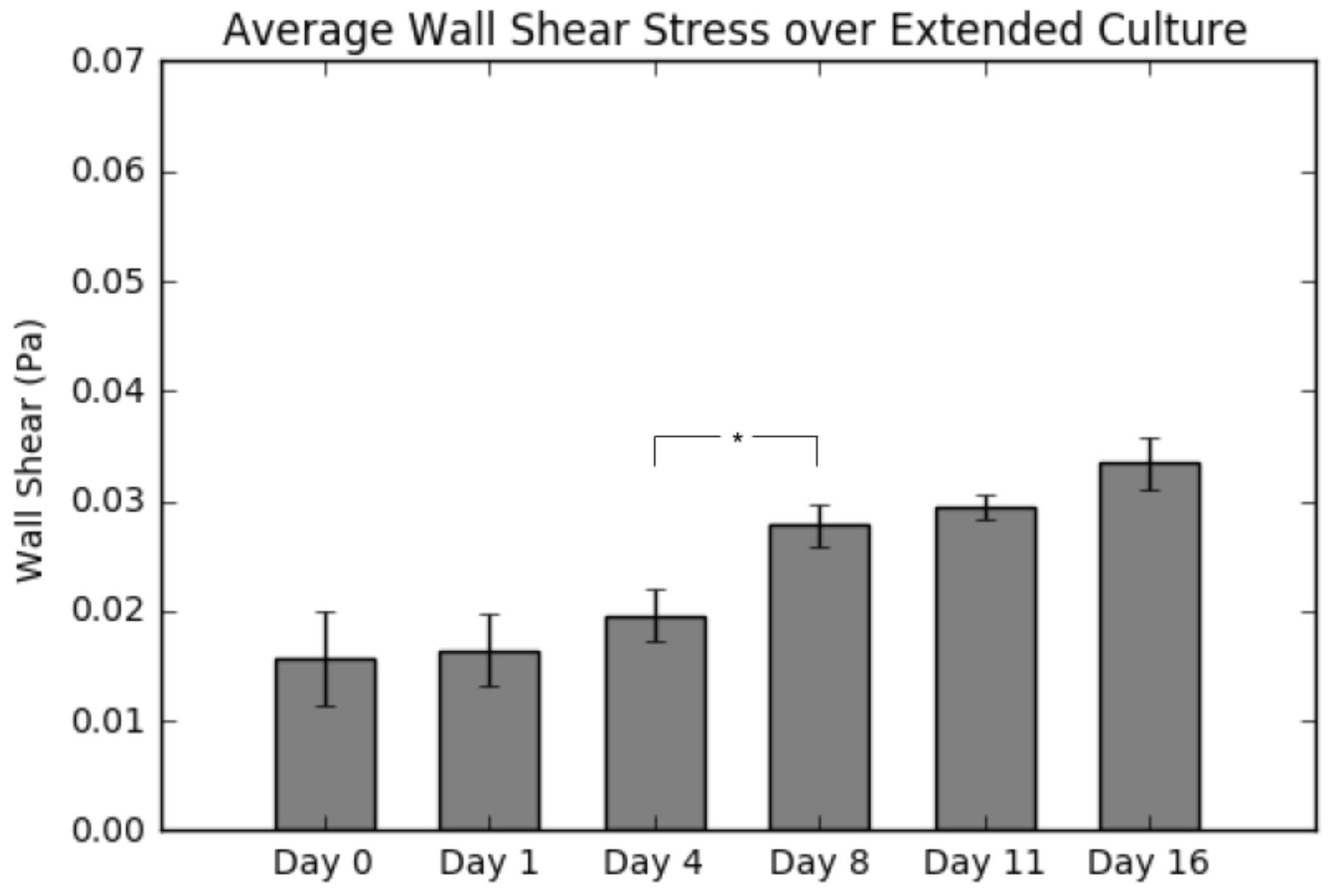
2.5. Average Wall Shear Stress

Figure 7 displays the average wall shear stress calculated from simulations following construct culture, resection, imaging and reconstruction. Indeed, the results do show a continuous increase in shear as culture time increases, which is consistent with the results presented in Figure 5. The most significant takeaway from this graph is the large jump in average wall shear between Day 4 and Day 8, due to matrix clogging the pores, consistent with the calcium deposition results (Figure 2).

3. Discussion

Following destructive analysis of the constructs, we evaluated the average wall shear stress per construct as a function of culture time. As seen in Figure 7, the average shear stress remains statistically the same throughout the first four days of culture; however, after Day 8, there is a continual increase in the value to the end of the culture period (113% by Day 16). This finding is in agreement with theoretical estimations of shear forces in scaffolds having similar levels of tissue formation [13]. Furthermore, it also confirms our hypothesis about bone tissue engineered cultures; that the shear stress experienced by the cells will increase significantly during culture, if the circulation fluid flow remains constant. We attribute this to extracellular matrix deposition resulting in a clogging of the construct pores. By holding the circulation fluid flow constant and simultaneously decreasing the pore sizes, we effectively are increasing the fluid velocity within the construct interior and, along with it, the wall shear stress. Considering the influence of shear rate on osteoblastic differentiation, it is evident that a continuous increased shear rate exposure will potentially accelerate the differentiation towards an osteoblastic lineage. Obviously, if the initial shear rates are near the range of flow-induced detachment, the observed increase could lead to undesirable detachment, implying the need for further investigating the shear levels at which detachment occurs.
After evaluating the construct reconstructions, we can see a clear correlation to the amount of mineralized tissue and an overall increase in the magnitude of wall shear experienced within the pores of the construct. Indeed, this relationship is obvious in both Figure 5, showing the frequency distributions, and Figure 6, which shows the wall shear heat maps. For the former, the distributions show an increased frequency of elevated shear stress as culture time increases, supporting the aforementioned increase in average wall shear stress. This finding is consistent when evaluating the heat maps. As culture time increases, there is a higher density of elevated shear seen within the constructs. This increase is most pronounced after Days 8–11, which, according to the reconstructions, are when large amounts of mineralized tissue starts depositing.
Additionally, the scaffold cellularity and the levels of mineralized tissue deposited were evaluated. As seen in Figure 1, a seeding efficiency of 40% was achieved, higher than most perfusion-based seeding methods, and can be directly attributed to the oscillatory seeding protocol we established in previous studies. Following the complete seeding process, the seeding efficiency drops further to 28% at Day 4 with the addition of a higher unidirectional fluid flow established at the end of Day 1. We believe that the decrease in cellularity seen between Day 1 and Day 4 is due to the change from basic maintenance flow employed immediately after seeding until Day 1 (0.15 mL/min) to culture flow beyond Day 1 (0.5 mL/min), and potentially causing a portion of cells to detach from the scaffold, especially those that form aggregates that are loosely bound to the surface. However, it must be noted that this drop can also be attributed to cell death or apoptosis, as seen in previous studies [4,5].
In Figure 2, a spike in calcium production is seen between Day 4 and Day 8. The point at which the spike occurs remains a critical parameter in bone tissue engineering research and better understanding of the factors influencing it will result in more efficient scheduling of culturing bone tissue engineering constructs in vitro. Recent studies identifying the initiation of extensive osteoblastic differentiation using nondestructive metabolic monitoring may allow us in future studies to better predict the exact timing of mineralization and thus allow for accurate prediction of the end of the culture period [5].
Figure 3 and Figure 4 demonstrate qualitatively that the mineralized tissue begins developing from the outer layer of the top surface of the scaffold directly exposed to the fluid flow. This result contradicts our previous assumption of a homogeneous cell distribution and cannot be justified by any localized fluid shear forces. It is potentially an artifact due to the scaffold radius being slightly larger than the bioreactor cassette, which causes both a more snug fit, but also a decreased porosity at the edges in contact with the wall; thusly, this presents an environment where cells can attach in greater numbers due the larger surface area available for attachment. Such a phenomenon is not expected to occur in rigid three-dimensional scaffold, but it will persist whenever deformable meshes are utilized, as is in this case.
In addition, Figure 3 shows an increase in mineralized tissue found utilizing μ CT between Day 8 and Day 11. We believe this lag time is due to the cells beginning to deposit calcium that is not dense enough to be picked up during imaging segmentation around Day 8. Along with this, Figure 4 shows the 2D images obtained from μ CT with the growing tissue highlighted in red. These images illustrate the state of the construct at the end of culture and give insight into the density of mineralization that would occur if culture continued. It is to be expected that the soft tissue visualized in the image will eventually transition into fully-mineralized tissue.

4. Materials and Methods

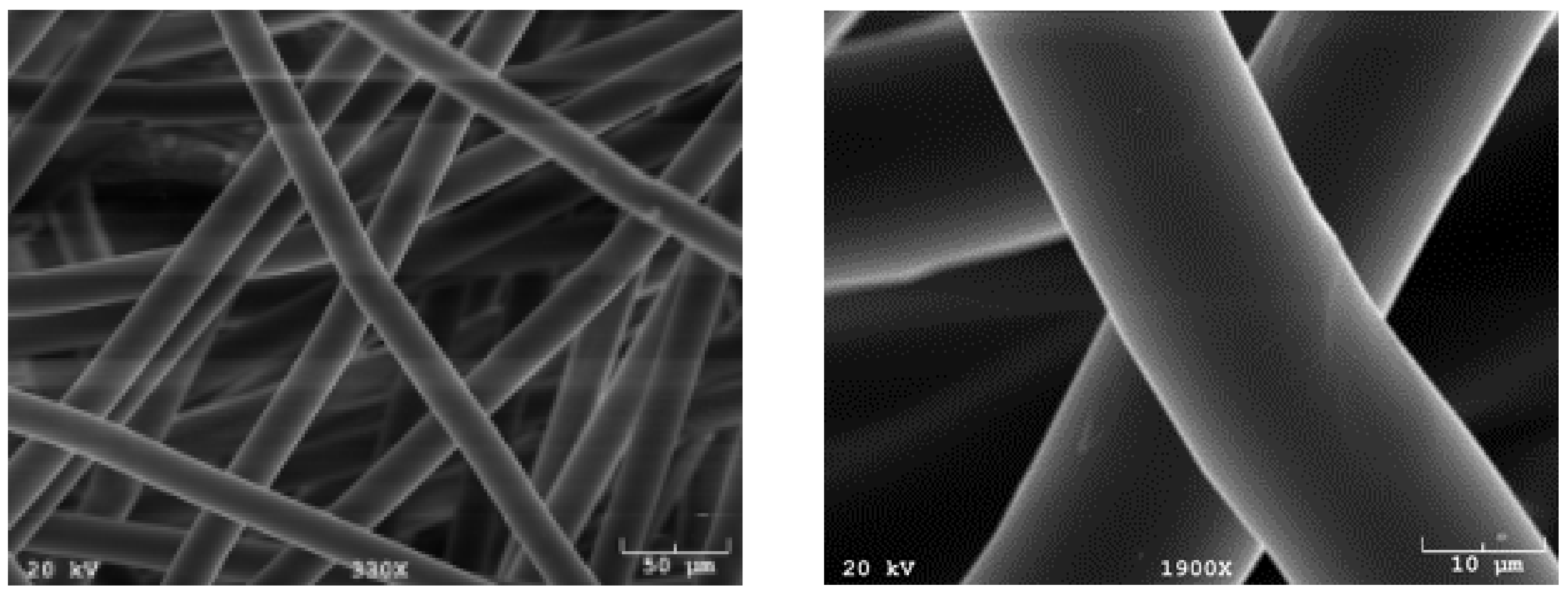
4.1. Scaffold Manufacturing

Poly(l-lactic acid) (PLLA; Grade 6251D; 1.4% D enantiomer; 108,500 MW; 1.87 PDI; NatureWorks LLC) non-woven fiber mesh scaffolds were produced via spunbonding, as previously indicated [22]. Scaffolds were cut from an 8 mm-thick PLLA mat, resulting in a porosity of 88% and a radius of 3.5 mm. A Nikon HFX-II microscope (Nikon Corporation, Tokyo, Japan) was used to evaluate fiber diameter, found to be 24.5 μ m, and was confirmed by scanning electron microscopy, shown in Figure 8.

4.2. Cell Expansion, Seeding and Culture

Adult mesenchymal stem cells were extracted from the tibias and femurs of male Wistar rats (Harlan Laboratories, Inc., Indianapolis, IN, USA) using methods identified in previous publications [1,4]. Cells were cultured at 37 C and 5% CO 2 in standard minimum essential medium eagle alpha modification ( α -MEM) (Invitrogen, Thermo Fisher Scientific corporation, Waltham, MA, USA) supplemented with 10% fetal bovine serum (Atlanta Biologicals, Flowery Branch, GA, USA) and 1% antibiotic-antimycotic (Invitrogen). Passage 2 cells were used for this study at a density of two million cells/mL for scaffold seeding.
We prepped the scaffolds for cell seeding using an established pre-wetting technique [5]. Vacuum air removal of scaffolds was conducted in 75% ethanol. Pre-wet scaffolds were placed in cassettes within a flow perfusion bioreactor for one hour in α -MEM to remove any remaining ethanol [23,24]. Schematics of the perfusion system used for this study may be found in Figure 9. Following the removal of ethanol, two million MSCs/150 μ L of osteogenic α -MEM were pipetted in each scaffold chamber. The seeding mixture was dynamically perfused at 0.15 mL/min, forwards and backwards, in five-minute intervals for two hours. Osteogenic media consist of standard α -MEM supplemented with dexamethasone, beta-glycerophosphate and ascorbic acid, which have been shown to induce osteogenic differentiation [25]. After dynamic seeding, the bioreactor was allowed to rest for two hours, without flow, to facilitate cell attachment. Finally, osteogenic α -MEM was continuously perfused at a rate of 0.5 mL/min for the remainder of the culture period. Scaffolds were collected for analysis at Days 1, 4, 8, 11 and 16.

4.3. Construct Cellularity

The number of cells present in each construct was evaluated using the fluorescent PicoGreen® dsDNA assay (Invitrogen). At each sacrificial time point, the construct was removed from the cassette and rinsed in PBS to remove any cells not adhered to the scaffold. Subsequently, the scaffolds were cut into eight pieces, placed in 1 mL of deionized (DI) H 2 O and stored at −20 C. Each construct underwent three freeze/thaw cycles to lyse the cells. Fluorescent analysis was conducted on a Synergy HT Multi-Mode Microplate Reader (BioTek Instruments, Inc., Winooski, VT, USA) at an excitation wavelength of 480 nm and an emission wavelength of 520 nm. All samples and standards were run in triplicate. Resulting values were then divided by the previously-determined dsDNA content per cell.

4.4. Construct Calcium Deposition

Calcium deposition was measured utilizing the scaffolds following the freeze/thaw cycles of the previous section. The solution was measured with a calcium colorimetric assay (Sigma-Aldrich Corporation, St. Louis, MO, USA, Cat. # MAK022). Samples were read on a Synergy HT Multi-Mode Microplate Reader (Bio-Tek) at an absorbance of 575 nm. All samples and standards were run in triplicate.

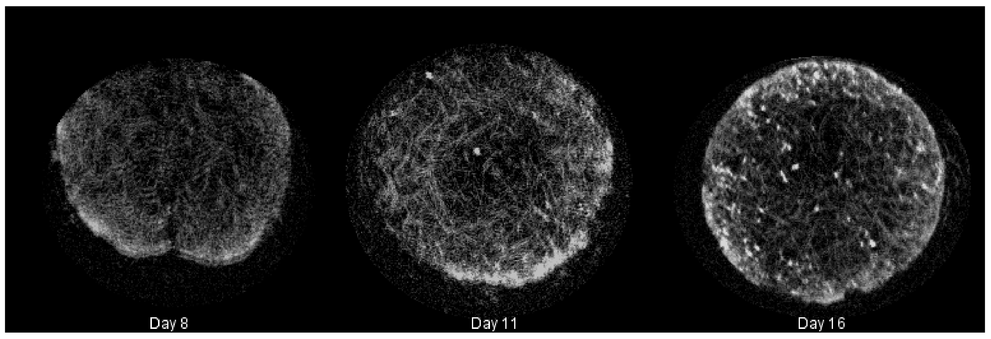
4.5. Imaging and Reconstruction

Micro-computed tomography was used to non-destructively scan the scaffolds at a resolution of 20 μ m and 45 kV energy (Quantum FX, Perkin Elmer, Waltham, MA, USA; L10101, Hamamatsu Photonics, Hamamatsu, Japan; PaxScan 1313, Varian Medical Systems, Palo Alto, CA, USA). The resulting 2D image slices were filtered, thresholded and stacked using the open-source visualization software 3D Slicer (slicer.org). Following reconstruction, the porosity of the digital scaffold was measured and compared to the actual spunbonded scaffolds in order to assure a proper segmentation. Using methods described in a previous publication, we also identified in each construct three different materials (polymer scaffold, soft tissue and mineralized tissue). This was done using a segmentation method that allowed us to distinguish between the aforementioned materials, based on their attenuation to X-rays and structural differences. Details for the methodology appear in a previous study [26]. For this study, we investigated a total of six time points (three constructs per time point).

4.6. CFD Simulations

Simulations were performed via the lattice Boltzmann method implemented using a previously-validated custom in-house lattice Boltzmann code, which has been extensively utilized for computing surface shear stresses on μ CT reconstructions [2,17,27].

Lattice Boltzmann Simulations

The lattice Boltzmann method (LBM) is a numerical technique for simulating fluid flow that consists of solving the discrete Boltzmann equation [28,29]. In addition to its computational advantages such as inherent parallelizability on high-end parallel computers [30,31] and relative ease of implementation, LBM techniques have been used in a wide spectrum of applications including turbulence [32], non-Newtonian flows [33,34,35] and multiphase flows [36]. More importantly, for the present application, LBM is especially appropriate for modeling pore-scale flow through porous media (such as scaffolds) due to the simplicity with which it handles complicated boundaries [2,12,18].
LBM is based on the discrete Boltzmann equation, which is an evolution equation for a particle distribution function, calculated as a function of space and time [37] as follows:
f i ( x + e i Δ t , t + Δ t ) = f i ( x , t ) + Ω i ( x , t ) ± f f i
where x represents the particle position, t is time, Δ t is the evolution time step, e is the microscopic velocity, Ω is the collision operator, f i is the particle distribution function, f i e q is the equilibrium particle distribution function and f f i is the forcing factor. The terms on the right-hand side of Equation (1) describe the three steps of the LBM algorithm: streaming, collision and forcing steps. In the streaming stage, the particle distribution function f i at position x and time t moves in the direction of the velocity to a new position on the lattice at time t + Δ t . The collision stage subsequently computes the effects of collisions that have occurred during movements in the streaming step, which is considered a relaxation towards equilibrium. The collision term can be computed for single-relaxation time (SRT) or multiple-relaxation time LBM models. The SRT approximation given by Bhatnagar, Gross and Krook (BGK) [38] is common. It is expressed as:
Ω i ( x , t ) = - 1 τ ( f i - f i e q )
The particle equilibrium distribution function f i e q is given as:
f i e q ( x ) = w i ρ ( x ) 1 + 3 e i U i c 2 + 9 ( e i U i ) 2 c 4 - 3 2 U i 2 c 2
where c is the lattice speed and defined as c = Δ x Δ t , Δ x is the lattice constant, iis an index that selects between possible discrete velocity directions (e.g., i = 0, 1, 2, …, 14 for the D3Q15 lattice), w i is a lattice dependent weighting factor, ρ is the fluid density and U is the macroscopic fluid velocity. The time τ is the time scale by which the particle distribution function relaxes to equilibrium and is related to kinematic fluid viscosity using:
v = 1 3 τ - 1 2
During the forcing step of the algorithm, a pressure drop is specified by adding a forcing factor f f i to the fluid particle distribution components moving in the positive stream-wise direction and by subtracting from those in the negative direction.
The final stage of the algorithm involves computing the macroscopic fluid density ρ and velocity U at any instant using the conservation equations of mass and momentum given as:
ρ = i = 0 n f i
ρ U i = i = 0 n f i e i
A custom-written, in-house code was developed for this work, and a detailed description may be found in previous publications [2,17,39]. The three-dimensional, 15 lattice (D3Q15) for LBM [40], in conjunction with the single-relaxation time approximation of the collision term given by Bhatnagar, Gross and Krook [38], was used to perform simulations. LBM results have been validated for several flow cases for which analytical solutions are available: forced flow in a slit, flow in a pipe and flow through an infinite array of spheres [2].
Due to the computationally-intensive nature of fluid flow simulations in scaffolds, representative portions cut from whole scaffolds are used. In this work, a single cuboid portion was extracted from the center of the 3D scaffold reconstruction to avoid end effects in flow simulations. The resulting simulation domain size was 153 μ m × 277 μ m × 221 μ m, with the center of the domain located at the center of the scaffold. Periodic boundary conditions were applied in all three directions, in order to approximate the whole scaffold. In addition, it was assumed that the whole extracellular matrix (ECM) was a rigid, non-permeable domain.
A no-slip boundary condition was applied at wall faces using the “bounce-back” technique [29]. To take advantage of the inherent LBM parallelizability, the domain was decomposed using message passing interface [17]. Simulation convergence was defined as when the minimum, average and highest velocities computed for the simulation domain vary by at least 0.001% for two consecutive time steps.
In order to estimate the mechanical stimulation of the cells by the flow of the culture media, the fluid-induced shear stresses on the surface of the scaffold were calculated following a scheme suggested by Porter et al. [18]. Here, the total stress stress tensor σ is represented by a summation of the hydrostatic pressure p and the viscous (also known as deviatoric) stress tensor τ :
σ i j = - p δ i j + τ i j
where δ i j is the unit tensor, such that δ i j is 1 if i = j and 0 if i j .
While the former is assumed to be negligible, the latter is the component of the total stress tensor that is of interest since as it is responsible for shearing the cells. Because it describes how momentum is transported across the fluid layers due to velocity shear, it must be related to the deformation tensor:
D i j = 1 2 ( U + U T ) + 1 2 ( U - U T )
This tensor can be decomposed into a symmetric (rate of strain) and an anti-symmetric (vorticity) contributions. Furthermore, we assume that the constitutive relationship between the viscous stress and the rate of strain is linear: in other words, the fluid is Newtonian, with a constant viscosity. Consequently, the viscous stress tensor depends only on the symmetric component of the deformation tensor due to this assumption. Hence, the shear stress at every location within the scaffold was calculated using the following equation, where σ is the shear stress tensor and U is local velocity vector:
σ ̲ ̲ = μ 1 2 ( U + U T )
The derivatives for the velocity field were approximated numerically using the centered finite difference method (Equations (10)–(12)), where lu is the length of one side of an element in the LBM model. The same was done for the partials of U y and U z . Following this, the symmetric strain matrices were found by adding the 3 × 3 partials matrix for each field location to its own transpose.
d U x d x ( i , j , k ) = U x ( i + l u , j , k ) - U x ( i - l u , j , k ) 2 × l u
d U x d y ( i , j , k ) = U x ( i , j + l u , k ) - U x ( i , j - l u , k ) 2 × l u
d U x d z ( i , j , k ) = U x ( i , j , k + l u ) - U x ( i , j , k - l u ) 2 × l u
Finally, eigenvalues of the symmetric matrix were obtained using the Jacobi method, and the largest absolute-value eigenvalue (i.e., largest principal component of the tensor) for each fluid voxel was used to determine the stresses experienced by the cells.
The fluid dynamic viscosity was 0.01 g c m · s , which is close to that of α -MEM supplemented with 10% FBS typically used in cell culturing experiments [41]. Velocity vectors used in calculations were derived from a flow rate of 0.1 mL/min. Computed shear stress values are the largest eigenvalues of σ ̲ ̲ . Stress maps generated using Tecplot 360 EX 2016 (Tecplot Inc., Bellevue, WA, USA) were used to visualize computed shear stresses. Additionally, we modeled the ECM as an impermeable wall without elasticity (static mesh) and did not distinguish between hard and soft ECM during the computations.

4.7. Statistical Analysis

A one-way analysis of variance (ANOVA) was used to compare the mean ± the standard deviation of pore measurements, in which Tukey’s honestly significant difference (HSD) test was performed to identify significant differences (p-value < 0.05). One-way ANOVA and Tukey’s HSD were used for the rest of the results. All statistical analysis was performed using a custom Python code utilizing the open source Numpy, matplotlib and SciPy libraries.

5. Conclusions

In the presented manuscript, we hypothesized that the distribution of fluid shear present at the walls of a construct cultured under osteoconductive conditions will exhibit higher magnitudes as culture increases. In order to accomplish this, rat mesenchymal stem cells were dynamically seeded on 85% porous spunbonded poly(l-lactic acid) and cultured with osteogenic media for up to 16 days in a flow perfusion bioreactor. Following culture, these constructs were either destructively evaluated with assays for cellularity and calcium deposition or imaged using μ CT and reconstructed to allow for CFD simulations to be performed. Average shear stress values and shear stress frequency distributions obtained from simulations were compared with the assays and confirmed our original hypothesis. In terms of the calcium quantification assay, a spike is seen around Day 8. This finding is supported by the reconstructions, where imaging identified an increase in mineralized tissue between Days 8 and 11. Additionally, the shear distribution heat maps show elevated magnitudes of shear stress in the same time period. Finally, we proved that both the shear stress distributions and the average shear stress per construct consistently increase as a function of culture time. This is due to mineralization occurring within the pores of the scaffold, decreasing pore diameter and effectively increasing velocity within the pores. In future studies, a correlation or algorithm may be developed that will give users the ability to predict, for the culture period, fluid shear distributions in bone tissue engineered cultures using μ CT images of empty scaffolds, fluid dynamic simulations on the reconstructions and nondestructive metabolic monitoring that allows for the identification of the point of sharp increase of mineralized deposition.

Acknowledgments

The authors acknowledge support from Ghani Muhammed and Hong Liu for imaging assistance. This work was funded in part by the Gustavus and Louise Pfeiffer Research Foundation and the Oklahoma Center for the Advancement of Science and Technology (HR13-214). C.W. gratefully acknowledges fellowship funding from the Oklahoma Louis Stokes Alliance for Minority Participation (OK-LSAMP) Bridge to the Doctorate, Cohort 6 (EHR/HRD (Education & Human Resources/Human Resource Development) #1249206). Any opinions, findings, conclusions or recommendations expressed in this material are those of the authors and do not necessarily reflect the views of the Gustavus and Louise Pfeiffer Research Foundation, Oklahoma Center for the Advancement of Science and Technology, or the National Science Foundation.

Author Contributions

C.W. and V.I.S. conceived of and designed the experiments. C.W. performed cell culture, performed bioreactor experiments, performed image analysis, performed reconstructions, performed data analysis and wrote the manuscript. O.E.K. performed LBM simulations, performed data analysis and wrote the manuscript. R.S.V. and V.I.S. performed data analysis and wrote the manuscript.

Conflicts of Interest

The authors declare no conflict of interest. The founding sponsors had no role in the design of the study; in the collection, analyses or interpretation of data; in the writing of the manuscript; nor in the decision to publish the results.

References

  1. VanGordon, S.B. Three-Dimensional Bone Tissue Engineering Strategies Using Polymeric Scaffolds. Ph.D. Thesis, The University of Oklahoma, Norman, OK, USA, 2012. [Google Scholar]
  2. Voronov, R.; VanGordon, S.; Sikavitsas, V.I.; Papavassiliou, D.V. Computational modeling of flow-induced shear stresses within 3D salt-leached porous scaffolds imaged via micro-CT. J. Biomech. 2010, 43, 1279–1286. [Google Scholar] [CrossRef] [PubMed]
  3. Melchels, F.P.; Tonnarelli, B.; Olivares, A.L.; Martin, I.; Lacroix, D.; Feijen, J.; Wendt, D.J.; Grijpma, D.W. The influence of the scaffold design on the distribution of adhering cells after perfusion cell seeding. Biomaterials 2011, 32, 2878–2884. [Google Scholar] [CrossRef] [PubMed]
  4. Alvarez-Barreto, J.F.; Linehan, S.M.; Shambaugh, R.L.; Sikavitsas, V.I. Flow perfusion improves seeding of tissue engineering scaffolds with different architectures. Ann. Biomed. Eng. 2007, 35, 429–442. [Google Scholar] [CrossRef] [PubMed]
  5. Alvarez-Barreto, J.F.; Sikavitsas, V.I. Improved mesenchymal stem cell seeding on RGD-modified poly(l-lactic acid) scaffolds using flow perfusion. Macromol. Biosci. 2007, 7, 579–588. [Google Scholar] [CrossRef] [PubMed]
  6. Du, D.J.; Furukawa KS, U.T. 3D culture of osteoblast-like cells by unidirectional or oscillatory flow for bone tissue engineering. Biotechnol. Bioeng. 2009, 102, 1670–1678. [Google Scholar] [CrossRef] [PubMed]
  7. Papantoniou, I.; Guyot, Y.; Sonnaert, M.; Kerckhofs, G.; Luyten, F.P.; Geris, L.; Schrooten, J. Spatial optimization in perfusion bioreactors improves bone tissue-engineered construct quality attributes. Biotechnol. Bioeng. 2014, 111, 2560–2570. [Google Scholar] [CrossRef] [PubMed]
  8. Campolo, M.; Curcio, F.; Soldati, A. Minimal perfusion flow for osteogenic growth of mesenchymal stem cells on lattice scaffolds. AIChE J. 2013, 59, 3131–3144. [Google Scholar] [CrossRef]
  9. Maes, F.; Van Ransbeeck, P.; Van Oosterwyck, H.; Verdonck, P. Modeling fluid flow through irregular scaffolds for perfusion bioreactors. Biotechnol. Bioeng. 2009, 103, 621–630. [Google Scholar] [CrossRef] [PubMed]
  10. Cioffi, M.; Boschetti, F.; Raimondi, M.T.; Dubini, G. Modeling evaluation of the fluid-dynamic microenvironment in tissue-engineered constructs: A micro-CT based model. Biotechnol. Bioeng. 2006, 93, 500–510. [Google Scholar] [CrossRef] [PubMed]
  11. Sandino, C.; Checa, S.; Prendergast, P.J.; Lacroix, D. Simulation of angiogenesis and cell differentiation in a CaP scaffold subjected to compressive strains using a lattice modeling approach. Biomaterials 2010, 31, 2446–2452. [Google Scholar] [CrossRef] [PubMed]
  12. Hossain, S.; Bergstrom, D.J.; Chen, X.B. A mathematical model and computational framework for three-dimensional chondrocyte cell growth in a porous tissue scaffold placed inside a bi-directional flow perfusion bioreactor. Biotechnol. Bioeng. 2015, 112, 2601–2610. [Google Scholar] [CrossRef] [PubMed]
  13. Guyot, Y.; Luyten, F.P.; Schrooten, J.; Geris, L. A three—Dimensional computational fluid dynamics model of shear stress distribution during neotissue growth in a perfusion bioreactor. Biotechnol. Bioeng. 2015, 112, 2591–2600. [Google Scholar] [CrossRef] [PubMed]
  14. Guyot, Y.; Papantoniou, I.; Luyten, F.P.; Geris, L. Coupling curvature-dependent and shear stress-stimulated neotissue growth in dynamic bioreactor cultures: A 3D computational model of a complete scaffold. Biomech. Model. Mechanobiol. 2015, 15, 169–180. [Google Scholar] [CrossRef] [PubMed]
  15. Nava, M.M.; Raimondi, M.T.; Pietrabissa, R. A multiphysics 3D model of tissue growth under interstitial perfusion in a tissue-engineering bioreactor. Biomech. Model. Mechanobiol. 2013, 12, 1169–1179. [Google Scholar] [CrossRef] [PubMed]
  16. Checa, S.; Prendergast, P.J. A Mechanobiological Model for Tissue Differentiation that Includes Angiogenesis: A Lattice-Based Modeling Approach. Ann. Biomed. Eng. 2009, 37, 129–145. [Google Scholar] [CrossRef] [PubMed]
  17. Voronov, R.S.; VanGordon, S.B.; Sikavitsas, V.I.; Papavassiliou, D.V. Distribution of flow-induced stresses in highly porous media. Appl. Phys. Lett. 2010, 97, 024101. [Google Scholar] [CrossRef]
  18. Porter, B.; Zauel, R.; Stockman, H.; Guldberg, R.; Fyhrie, D. 3-D computational modeling of media flow through scaffolds in a perfusion bioreactor. J. Biomech. 2005, 38, 543–549. [Google Scholar] [CrossRef] [PubMed]
  19. Childers, E.P.; Wang, M.O.; Becker, M.L.; Fisher, J.P.; Dean, D. 3D printing of resorbable poly(propylene fumarate) tissue engineering scaffolds. MRS Bull. 2015, 40, 119–126. [Google Scholar] [CrossRef]
  20. McCoy, R.J.; Jungreuthmayer, C.; O’Brien, F.J. Influence of flow rate and scaffold pore size on cell behavior during mechanical stimulation in a flow perfusion bioreactor. Biotechnol. Bioeng. 2012, 109, 1583–1594. [Google Scholar] [CrossRef] [PubMed]
  21. Wendt, D.; Marsano, A.; Jakob, M.; Heberer, M.; Martin, I. Oscillating perfusion of cell suspensions through three-dimensional scaffolds enhances cell seeding efficiency and uniformity. Biotechnol. Bioeng. 2003, 84, 205–214. [Google Scholar] [CrossRef] [PubMed]
  22. VanGordon, S.B.; Voronov, R.S.; Blue, T.B.; Shambaugh, R.L.; Papavassiliou, D.V.; Sikavitsas, V.I. Effects of scaffold architecture on preosteoblastic cultures under continuous fluid shear. Ind. Eng. Chem. Res. 2011, 50, 620–629. [Google Scholar] [CrossRef]
  23. Kasper, F.K.; Liao, J.; Kretlow, J.D.; Sikavitsas, V.I.; Mikos, A.G. Flow Perfusion Culture of Mesenchymal Stem Cells for Bone Tissue Engineering; StemBook, Harvard Stem Cell Institute: Cambridge, MA, USA, 2008. [Google Scholar]
  24. Bancroft, G.N.; Sikavitsas, V.I.; Van Den Dolder, J.; Sheffield, T.L.; Ambrose, C.G.; Jansen, J.A.; Mikos, A.G. Fluid flow increases mineralized matrix deposition in 3D perfusion culture of marrow stromal osteoblasts in a dose-dependent manner. Proc. Natl. Acad. Sci. USA 2002, 99, 12600–12605. [Google Scholar] [CrossRef] [PubMed]
  25. Porter, J.R.; Ruckh, T.T.; Popat, K.C. Bone tissue engineering: A review in bone biomimetics and drug delivery strategies. Biotechnol. Prog. 2009, 25, 1539–1560. [Google Scholar] [CrossRef] [PubMed]
  26. Voronov, R.S.; VanGordon, S.B.; Shambaugh, R.L.; Papavassiliou, D.V.; Sikavitsas, V.I. 3D tissue-engineered construct analysis via conventional high-resolution microcomputed tomography without X-ray contrast. Tissue Eng. Part C Methods 2013, 19, 327–335. [Google Scholar] [CrossRef] [PubMed]
  27. Pham, N.H.; Voronov, R.S.; VanGordon, S.B.; Sikavitsas, V.I.; Papavassiliou, D.V. Predicting the stress distribution within scaffolds with ordered architecture. Biorheology 2012, 49, 235–247. [Google Scholar] [PubMed]
  28. Chen, S.; Doolen, G.D. Lattice Boltzmann method for fluid flows. Annu. Rev. Fluid Mech. 1998, 30, 329–364. [Google Scholar] [CrossRef]
  29. Sukop, M.C.; Thorne, D.T., Jr. Lattice Boltzmann Modeling an Introduction for Geoscientists and Engineers; Springer: Berlin, Germany; New York, NY, USA, 2006; 172p. [Google Scholar]
  30. Kandhai, D.; Koponen, A.; Hoekstra, A.G.; Kataja, M.; Timonen, J.; Sloot, P.M.A. Lattice-Boltzmann hydrodynamics on parallel systems. Comput. Phys. Commun. 1998, 111, 14–26. [Google Scholar] [CrossRef]
  31. Wang, J.Y.; Zhang, X.X.; Bengough, A.G.; Crawford, J.W. Domain-decomposition method for parallel lattice Boltzmann simulation of incompressible flow in porous media. Phys. Rev. E 2005, 72, 016706. [Google Scholar] [CrossRef] [PubMed]
  32. Cosgrove, J.A.; Buick, J.M.; Tonge, S.J.; Munro, C.G.; Greated, C.A.; Campbell, D.M. Application of the lattice Boltzmann method to transition in oscillatory channel flow. J. Phys. Math. Gen. 2003, 36, 2609–2620. [Google Scholar] [CrossRef] [Green Version]
  33. Gabbanelli, S.; Drazer, G.; Koplik, J. Lattice Boltzmann method for non-Newtonian (power-law) fluids. Phys. Rev. E 2005, 72, 046312. [Google Scholar] [CrossRef] [PubMed]
  34. Boyd, J.; Buick, J.; Green, S. A second-order accurate lattice Boltzmann non-Newtonian flow model. J. Phys. Math. Gen. 2006, 39, 14241–14247. [Google Scholar] [CrossRef] [Green Version]
  35. Yoshino, A.; Hotta, Y.; Hirozane, T.; Endo, M. A numerical method for incompressible non-Newtonian fluid flows based on the lattice Boltzmann method. J. Non-Newton. Fluid Mech. 2007, 147, 69–78. [Google Scholar] [CrossRef]
  36. Swift, M.R.; Orlandini, E.; Osborn, W.R.; Yeomans, J.M. Lattice Boltzmann simulations of liquid-gas and binary fluid systems. Phys. Rev. E 1996, 54, 5041–5052. [Google Scholar] [CrossRef]
  37. McNamara, G.; Zanetti, G. Use of the Boltzmann equation to simulate Lattice-gas automata. Phys. Rev. Lett. 1988, 61, 2332–2335. [Google Scholar] [CrossRef] [PubMed]
  38. Bhatnagar, P.L.; Gross, E.P.; Krook, M. A Model for Collision Processes in Gases. I. Small amplitude processes in charged and neutral one-component systems. Phys. Rev. 1954, 94, 511–525. [Google Scholar] [CrossRef]
  39. Voronov, R.S.; VanGordon, S.B.; Sikavitsas, V.I.; Papavassiliou, D.V. Efficient Lagrangian scalar tracking method for reactive local mass transport simulation through porous media. Int. J. Numer. Methods Fluids 2011, 67, 501–517. [Google Scholar] [CrossRef]
  40. Qian, Y.H.; Dhumieres, D.; Lallemand, P. Lattice Bgk models for Navier-Stokes equation. Europhys. Lett. 1992, 17, 479–484. [Google Scholar] [CrossRef]
  41. Lakhotia, S.; Papoutsakis, E.T. Agitation induced cell injury in microcarrier cultures—Protective effect of viscosity is agitation intensity dependent—Experiments and modeling. Biotechnol. Bioeng. 1992, 39, 95–107. [Google Scholar] [CrossRef] [PubMed]
Figure 1. Construct cellularity for each construct over the culture period. The horizontal dashed line indicates the initial amount of cells seeded. The vertical dotted line indicates the switch in flow rates, from 0.15 mL/min during seeding to 0.5 mL/min for culture. Values are given as the mean ± the standard error of the mean (n = 4).
Fluids 03 00025 g001
Figure 2. Calcium levels present within each construct over the culture period. The horizontal dotted line represents the background signal for an empty construct. Values are given as the mean ± the standard error of the mean (n = 4). The # signifies the significantly lowest value ( p < 0.01).
Fluids 03 00025 g002
Figure 3. Summary of mineralized tissue (hard extracellular matrix (ECM)) deposited in cultured constructs rendered during microcomputed tomography ( μ CT) with Simple Viewer for samples taken on Days 8, 11 and 16, respectively.
Fluids 03 00025 g003
Figure 4. (Left) 2D grayscale view of the scaffold after μ CT imaging. The top row is a view of the entire scaffold, while the bottom row is a magnified view of the indicated area of interest. (Right) 2D view of the scaffold after μ CT imaging with ECM indicated in red.
Fluids 03 00025 g004
Figure 5. Wall shear stress distributions based on the day a construct was removed from culture and imaged.
Fluids 03 00025 g005
Figure 6. Summary of wall shear stress heat maps for constructs cultured under osteoconductive conditions. (a) Wall shear heat maps for Day 1 (far left) to Day 11 (far right) obtained using the custom lattice Boltzmann method code. (b) Scale bar: values given in g cm · s 2 .
Fluids 03 00025 g006
Figure 7. Summary of average shear stress per layer for a 0.5 mL/min flow rate. Values are given as the mean ± the standard error of the mean (n = 3). Significance calculated via analysis of variance (ANOVA) with the Tukey honest significant difference (HSD) post-hoc analysis.
Fluids 03 00025 g007
Figure 8. Common synthetic polymeric scaffolds used for tissue engineering. Scaffolds manufactured using spunbonding and imaged using scanning electron microscopy (SEM).
Fluids 03 00025 g008
Figure 9. Schematic of the custom in-house perfusion bioreactor system. The right image shows the combination of the bioreactor body, scaffold cassettes and stand.
Fluids 03 00025 g009

