Abstract
Better mixing in the near-field region of jets with their surrounding fluid is of high interest for several industrial applications. Passive control that involves jet geometry modifications as compared to the traditional circular design is used in the present work. An analysis of the entrainment mechanism in the near jet-exit field is proposed for innovative hemispherical nozzles (circular and six-lobed). High-speed Time-Resolved Particle Image Velocimetry (TR-PIV) measurements are used to experimentally characterize the entrainment mechanism in these jets. The distributions of mean entrainment rates, shear layer growth, and momentum flux are investigated along the longitudinal direction within the near-field region of both circular and lobed hemispherical jets. Significant entrainment enhancement is found using the hemispherical geometry as a passive-control method. By comparing both investigated hemispherical nozzle geometries, it has been demonstrated that the lobed nozzle provides higher mixing rates compared to the circular jet. This enhancement in mixing can be attributed to the stronger streamwise vortex structures generated by the lobed nozzle geometry, which promote increased entrainment of the surrounding fluid.
1. Introduction
As industrial applications continue to evolve rapidly, there is a growing interest in optimizing faster and more efficient mixing processes in the near-field region of jets interacting with surrounding fluids. For example, the operation of mixing devices in combustion injection chambers, HVAC systems, and submarine or aircraft propulsion systems is of great interest to be optimal, effective, and less energy-consuming by controlling the jet flow inside such engineering systems. The entrainment of the surrounding fluid by the primary fluid of the jet plays a significant role in improving mixing processes [1,2,3,4].
Several turbulent jet studies proved that the inlet conditions (i.e., nozzle exit characteristics) control the behavior of the entire jet flow, especially in the jet’s mixing region. There are several strategies to control jet flows and enhance their mixing processes. One of these strategies, known as “passive-control”, involves jet geometry modifications that differ from the traditional circular design. This strategy has been adopted by researchers to investigate mixing performance between a jet flow (various geometries) and its surroundings using experimental measurements such as the high-speed TR-PIV [3,4,5,6].
The entrainment rate refers to the rate at which surrounding fluid (e.g., air) is drawn into a primary flow (e.g., a jet), and it quantifies the amount of surrounding fluid mixed with the jet flow per unit time [7]. Several studies showed that the entrainment rate increases considerably (up to 50%) in the near-field region of the jet (2De ≤ x ≤ 4De, where De is the equivalent diameter of the circular nozzle exit) when using non-circular jet geometries such as elliptic and rectangular jets. It was experimentally shown that the distribution of the entrainment rate has a spatial dependence in the near-field region of plane jet flows, along with an enhancement in mixing by the entrainment mechanism with a lobed (daisy) plane jet compared to a circular plane jet [1,2,3,4].
Nastase et al. [5] considered a lobed nozzle geometry for an innovative 3D air diffuser design. Two different designs of lobed nozzles were studied: a tubular lobed nozzle and a hemispherical lobed nozzle. Entrainment was studied using high-speed TR-PIV measurements. It was demonstrated that such nozzle geometries of a lobed jet, which can be integrated into 2D air diffusion devices, provide higher efficiencies in terms of induction capabilities. Sodjavi et al. [8] used PIV to study the flow fields in an impinging hemispherical lobed nozzle jet and compared the results to the performance of a traditional circular nozzle at a Reynolds number of 5620 based on the exit velocity. It was shown that the maximum wall shear rate was 93% higher for the lobed jet compared to the circular nozzle. It was also demonstrated that the maximum mass transfer was 35% higher in the case of the lobed nozzle.
At relatively low Reynolds numbers of turbulence regimes (3000–5000), previous studies [9,10,11] have demonstrated that large streamwise (S-W) structures, generated by the edges of the lobed jet exit, control the mixing processes through the entrainment mechanism (surrounding fluid induction). Additionally, it was suggested that lobed jets generate a transverse shear in the lobe troughs, which leads to a breakdown of the Kelvin–Helmholtz (K–H) structures into “rings”. Further development of S-W structures at discontinuity regions controls the lobed jet self-induction. This leads to less effect on the entrainment rate by the dynamics of the primary structures. Furthermore, it was shown that lobed jets play a considerable role in both shear production and the resulting vortical mechanisms. In addition, the deflection angles of lobes amplified shear production and managed vorticity fields in Large-Scale Structures (LSSs), which correlates well with transverse shear leading to increased mixing. The inclinations of the lobes themselves also create flow asymmetry, enhancing induction phenomena in the far-field region of lobed jets [9,10,11].
Several types of axisymmetric jets (e.g., sharp-edged orifice plates) were utilized in entrainment investigations for enhancing mixing processes. Azimuthal (K–H) and streamwise (S-W) vortices are the main Large-Scale Structures (LSSs) in such jets. Many researchers have investigated the generated vortices in jet flow to determine the role played by these structures in the entrainment process.
El Hassan et al. [3] conducted high-speed stereoscopic TR-PIV measurements to characterize the entrainment mechanism in the near-field region of jets (circular and six-lobed), both of sharp-edged 2D planar type at Re = 3600. The authors found that the distribution of the mean entrainment rate at different longitudinal locations has a radial spatial dependency near the jet core. In addition, at all longitudinal locations, the entrainment is enhanced using the lobed jet compared to the circular one. Furthermore, the authors used the instantaneous PIV profiles to obtain temporal evolutions of the entrainment downstream of the nozzle exit. It was found that for the planar lobed orifice jet, an axis-switching phenomenon exists at X/De = 1 and was responsible for the high complexity of flow dynamics and the significant entrainment enhancement compared to the circular one. The momentum flux, turbulent intensities, and turbulent kinetic energy (TKE) were also analyzed to better explain the enhanced mixing of the lobed jet core with its surrounding air compared to the circular jet.
In view of the relatively less studies performed on the 3D hemispherical nozzle jets, many researchers investigated the 2D planar diffusers. For instance, Bode et al. [12] investigated passive flow control methods to optimize ventilation in buildings. The focus was on lobed air diffusers, which showed better performance in thermal comfort compared to circular ones. Kannan et al. [13] performed numerical simulations as well as experiments to study turbulent isothermal jets from non-circular nozzles, focusing on the vortical structures and flow field behavior. Complex dynamics were observed in the near-field regions of jets. It was also concluded that by using non-circular nozzles, significantly different vortical structures (from those of axisymmetric nozzles) were obtained in the flow, showing changes in shape while moving downstream the nozzle, leading to better efficiencies in mixing.
Myeong et al. [14] investigated steam jet flow characteristics from different orifice nozzles. By analyzing the velocity distributions, the “vena-contracta” effect was observed at the jet exit. It was also concluded that passive control via modifications of orifice/nozzle geometry plays a considerable role in controlling jet velocities, leading to better jet spread rates and thermal performance. Seif et al. [15] studied non-circular nozzle jets, comparing the turbulent free jets from different nozzle geometries. It was concluded that the nozzle exit geometry significantly impacts jet development and turbulence levels, in which 3D jets are observed to achieve axisymmetric states far downstream of the nozzle exit, i.e., higher levels of mixing are potential in the near-field region of the 3D non-circular nozzle jets.
Pawlowska et al. [16] experimentally studied free jets emanating from non-circular nozzles. The vortex dynamics visualizing the flow oscillations were investigated at different Reynolds numbers (5000~10,000). It was reported that LLS (Kelvin–Helmholtz vortices) were developed due to low perturbations at the nozzle exit. Furthermore, neither the “vena-contracta” effects in the near-field regions nor longitudinal vortices from non-circular flows were observed. Sheng et al. [17] performed numerical simulations to study lobed jet mixing mechanisms. The flow fields’ structures were analyzed to find that lobed mixers enhance jet mixing for various engineering applications. The changes in mixing performance (in terms of velocity gradients of the jet and its surrounding fluid) based on passive-control geometry modifications of nozzle exits were positively increased. The mechanisms of streamwise vortex formation and breakdown along the jet’s flow in the longitudinal direction were also discussed.
Rohn et al. [18] examined the entrainment process with different nozzle geometries using high-speed stereo-PIV measurements. It was also confirmed that nozzle design via geometry modifications significantly affects the entrainment efficiencies. The authors reported increased entrainment rates by non-circular nozzle geometries, with the lobed one showing the highest improvement. Braganca et al. [19] compared the thermal comfort from HVAC diffusers with and without lobe insertion using PIV measurements. By analyzing the air flow patterns and interactions, the lobed nozzle jets were found to significantly improve thermal comfort without any increase in noise or pressure drop, especially at high flow rates.
Hashiehbaf and Romano [4] investigated the mixing enhancement of non-circular sharped-edges nozzles using the PIV measurements. Both the axis-switching and “vena-contracta” phenomena by non-circular jets were observed and found to affect the turbulence intensity. It was also confirmed that non-circular nozzles enhance mixing efficiencies, especially at lower Reynolds numbers (just after laminar-turbulent transition, Re ≈ 8000). By analyzing the mean velocities, turbulence, and velocity profiles for large/small scales mixing behavior, it was concluded that the complex dynamic behavior of non-circular nozzles makes them good mixing candidates for better thermal performance.
Salewski et al. [20] focused their studies on the mixing in circular and non-circular jets. It was concluded that the nozzle shape affects the spatial distribution of the passive scalar. In addition, distinct jet flow distributions from circular and non-circular nozzles were observed. It was also reported that the turbulence levels of the nozzle affect the number of peaks in the jet’s flow distributions. Rahman et al. [21] concluded that non-circular nozzles show enhanced mixing and entrainment rates in the near-field regions compared to the traditional circular ones at a constant effective nozzle exit area. The influence of nozzle geometry on coherent vortical structures in the interaction regions was also quantified.
Hashiehbaf and Romano [22] did an experimental study on circular and non-circular synthetic nozzle jets. By analyzing the turbulence properties, mixing rates, and entrainment, it was reported that synthetic nozzle jets introduce the “vena-contracta” and the axis-switching phenomena’ effects. Enhanced mixing behavior in the near-field regions was observed compared to the downstream continuous jets’ flows, with self-similarity found in all investigated nozzle jets for X/De > 5. Bennia et al. [23] investigated lobed and swirling turbulent thermal jets for HVAC systems. By comparing different nozzle geometries, it was concluded that six-lobed nozzle jets provide higher mixing rates while highlighting the importance of the jet type and design on mixing capacity. The need for further studies and the development of new air diffusers was also confirmed.
The development of advanced jet technologies necessitates innovative designs to enhance performance and mixing efficiency. Traditional orifices, characterized by simple geometries and abrupt flow transitions, are limited by significant energy losses and inadequate control of flow patterns. To overcome these limitations, we introduce a novel 3D nozzle design that optimizes the flow by incorporating a streamlined geometry, specifically tailored to enhance mixing through controlled turbulence generation. Unlike orifices, which primarily restrict flow or measure it, the proposed 3D nozzle efficiently converts pressure energy into kinetic energy, directing the jet with precision and reducing energy dissipation. This design leverages complex shapes, such as lobed hemispherical geometries, to achieve superior entrainment and mixing, making it ideal for applications in propulsion, fluid dynamics research, and industrial mixing processes. These 3D nozzles represent a significant advancement in jet technology, offering improved performance and greater adaptability to various operational conditions.
Therefore, the present paper aims to develop geometries of 3D hemispherical jets for further mixing enhancement as compared to the existing literature. Specifically, at some points, the 2D orifice jets (circular and lobed) are included as reference cases. Hence, high-speed stereoscopic TR-PIV measurements were conducted to further investigate the entrainment mechanism in circular and six-lobed hemispherical jets. The high-speed TR-PIV measurement technique aims at revealing intricate flow patterns, vortex dynamics, and unsteady phenomena specific to 3D geometries that have not been previously well understood. This deeper understanding of 3D nozzle performance opens new possibilities for optimizing industrial applications.
This paper is structured as follows: the entrainment behavior of jet flows utilizing the 3D hemispherical nozzles (circular and six-lobed) is quantified and described. The velocity field, the entrainment rate, the shear layer growth, and the momentum flux are all investigated over several longitudinal/axial locations in the near-field region of turbulent regime jets.
This paper provides a comparative analysis of the development of hemispherical lobed and circular nozzle jets, emphasizing the impact of nozzle geometry on mixing rates and vortex dynamics. Unlike prior studies that primarily focused on either planar or circular jets, this work uniquely investigates the role of hemispherical (circular and lobed) geometries in enhancing mixing through the generation of distinct streamwise vortices. The findings contribute novel insights into the entrainment mechanisms associated with lobed nozzle jets, which have not been extensively or sufficiently explored in the existing literature.
2. Experimental Procedures
2.1. Exit Nozzle Conditions of the Air Jet Facility
Two isothermal air jet flows are generated using two different types of innovative 3D exit nozzles comprising hemispherical six-lobed and circular designs, both with an exit diameter of 16 mm (equivalent diameter of 16 mm for the lobed nozzle), as shown in Figure 1. These nozzles are fabricated from 1.5 mm-thick aluminum sheet projected onto a hemispherical surface with a diameter of 40 mm. For a lobed nozzle, the plane dividing the width of the lobes is called the “major plane” while the plane intersecting the opposing troughs is called the “minor plane”. All dimensions are illustrated in Figure 1.
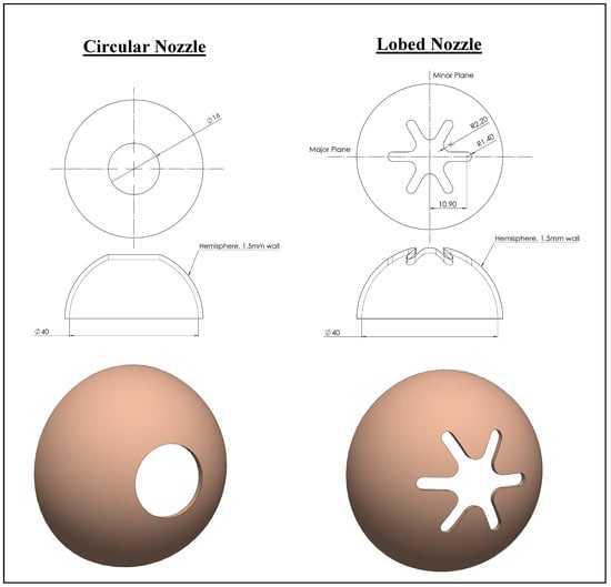
Figure 1.
Hemispheric nozzles’ geometries.
The air jet experimental facility is shown in Figure 2, including flow conditioning and seeding for the PIV measurements. Based on the volumetric flow rate measured a few millimeters downstream from the nozzle exit (X = 0.5De or X/De = 0.5), centerline exit velocity of air (U0m = 3.6 m/s), and effective equivalent diameter of the nozzle exit, the initial Reynolds number is found to be around 2600 for both air jet flows (circular and lobed) at lab environment temperature of 20 °C.
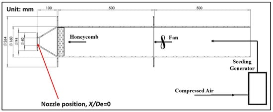
Figure 2.
Air jet experimental facility indicating the installation position of 16 mm nozzles.
The Reynolds number of approximately 2600 was chosen in order to study the jet behavior in the transitional regime, where large-scale vortex structures dominate. This choice facilitates clear observation and a comparison of coherent structures between circular and lobed jets. Similar Reynolds numbers have been used in previous studies [9,10,11] to investigate entrainment and vortex dynamics in non-circular jets.
2.2. TR-PIV Measurements of Jets
In this paper, the region of interest of jets’ flows along the longitudinal direction (over the x-axis) is 0 ≤ X/De ≤ 6.5, as this is where all coherent vortex structures are generated. To analyze the jet flows in the investigated region of interest, high-speed stereoscopic TR-PIV measurements were conducted. These advanced measurements were employed to capture all three components (3C) of the velocity field, from which hundreds of instantaneous spatial distributions of the 2D-2C velocities in the longitudinal direction (XY) of the jet flows were obtained and analyzed. The 2D-3C was used for the calculation of the entrainment rate.
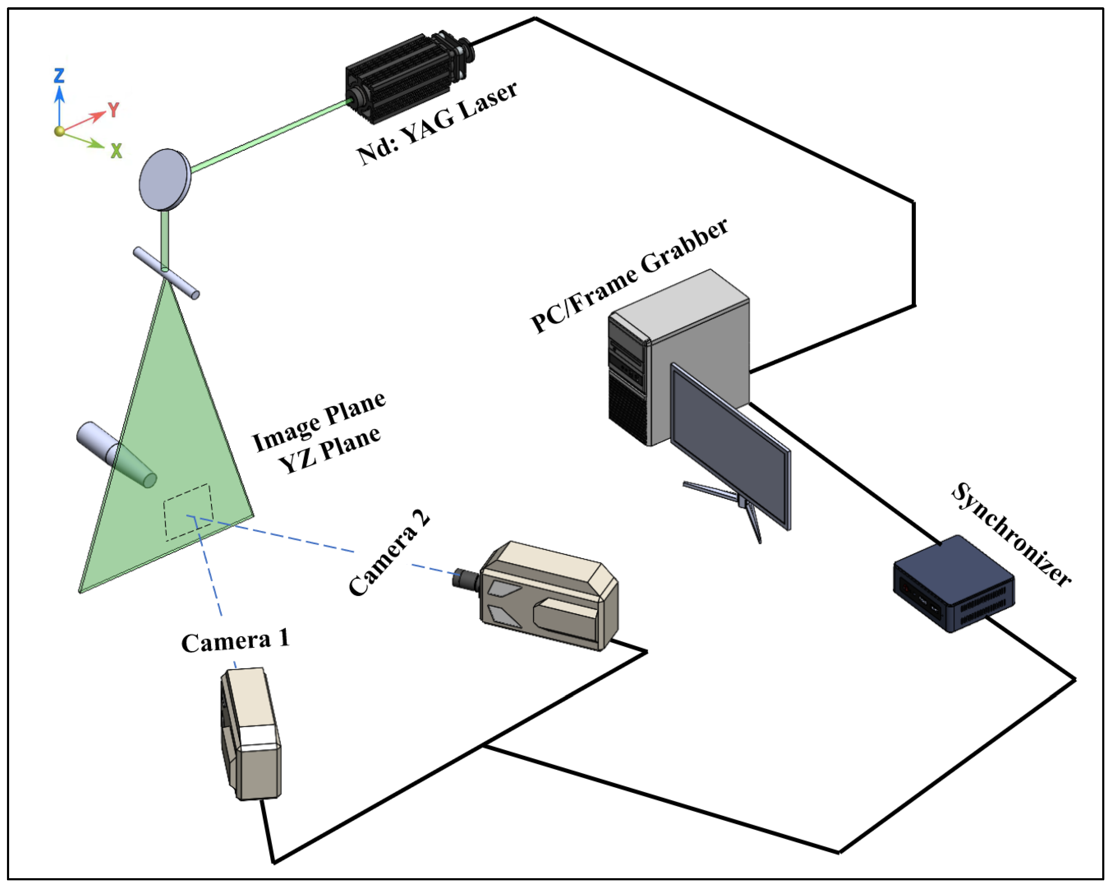
The high-speed stereoscopic TR-PIV system of this paper is shown in Figure 3. The high-speed stereoscopic TR-PIV system utilized in this investigation consists of two Phantom V9 cameras (1200 × 1632 pixels2) (https://www.phantomhighspeed.com/, accessed on 29 June 2025) and an Nd:YLF NewWave Pegasus laser (https://www.spectra-physics.com/en/, accessed on 29 June 2025) with 10 mJ energy and a wavelength of 527 nm. Operating at 500 Hz, the system captured 1000 image pairs (initial images) for each plane of each type of jet flow, resulting in a sequence of 500 synchronized photographs (final images), all with the air jets seeded using 1–2 μm olive oil droplets generated by a liquid seeding system. An olive oil droplet seeder was properly installed to better reflect the green laser light, which interacts with air flow molecules, toward the two photography cameras as oil droplets adhere to flow surfaces. It is worth mentioning that the seeding process of the green oil droplets was carefully tailored with the flow conditions and adjusted to improve the reflection function, providing better quantifications of the flow phenomena, as oil has a different refractive index than air.
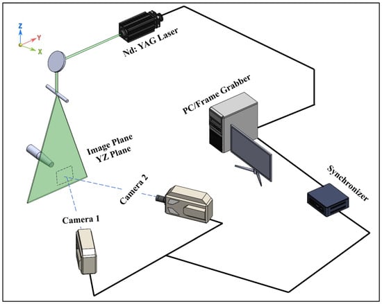
Figure 3.
A schematic shows the stereoscopic TR-PIV system used in this paper.
The cameras, mounted at a 45° angle relative to the light sheet plane, satisfy Scheimpflug conditions for optimal focus alignment. A 3D empirical stereo reconstruction method cross-correlates calibration images, achieving a spatial resolution of 59.9 μm/pixel within a Field Of View (FOV) of 97.7 × 62.4 mm2. Images were processed using an adaptive multigrid correlation algorithm, with an error detection rate of under 2%, corrected via bilinear interpolation. The final grid resolution was 0.59 mm with interrogation windows of 16 × 16 pixels and a vector spacing of 9.8 pixels. Particle image sizes averaged 2.5 × 2.5 pixels, avoiding peak locking artifacts. The system’s error rates for velocity measurements were 1%, 2%, and 2.5% for longitudinal, vertical, and transverse directions, respectively, with 0.09 m/s overall rms error.
Calculations of out-of-plane vorticity introduced bias and random errors, estimated as 0.8% and ±1.5% (95% confidence level). Turbulent kinetic energy errors, accounting for bias and statistical scattering, were ±4.2%. This streamlined methodology ensures high accuracy in velocity and vorticity measurements, supporting reliable analysis of the flow fields [6]. And the detailed principle of the stereoscopic PIV method is well described in [24,25,26,27]. Further relevant details on the PIV imaging system, its setup, data resolving and processing, and correlations are well-detailed in [27,28,29,30,31].
The PIV measurements were processed using interrogation windows of 32 × 32 pixels with 50% overlap, resulting in a vector spacing of 16 pixels. Each velocity field was obtained by averaging 500 image pairs. The center-plane velocity components (axial and radial) were extracted from the stereo PIV dataset by selecting the symmetry plane normal to the flow direction. An uncertainty analysis was conducted, considering factors such as image resolution, particle seeding density, and cross-correlation peak detection. The estimated uncertainty in the velocity magnitude is approximately ±2.4% of the centerline exit velocity, U0m.
3. Results and Discussion
3.1. Initial Conditions of Jets
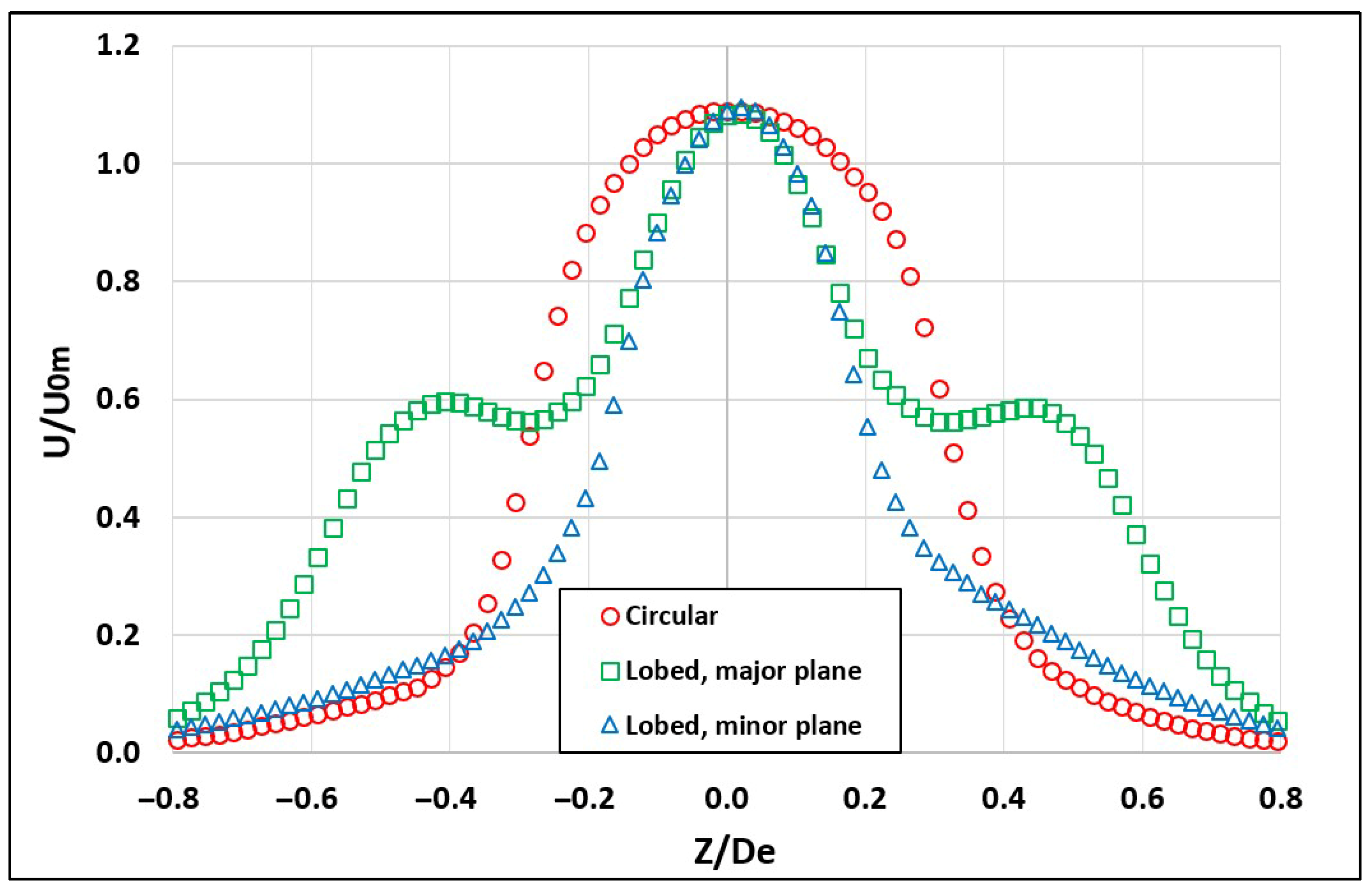
Near the exit of both the circular and six-lobed hemispherical jets (X/De = 0.1), the average distributions of the streamwise velocity and turbulent intensity were obtained as shown in Figure 4 and Figure 5, respectively. The turbulent intensity is represented by the root-mean-square (RMS) values of the axial velocity fluctuations. A laminar behavior is observed at the exit plane for both jets. Figure 4 shows a “smooth dome” shape of the mean streamwise velocity profile for the circular jet, whereas a sharper “dome” is observed for the minor plane of the lobed jet. A two-step distribution is also observed for the mean velocity profile in the major plane, indicating enhanced layered mixing, driven by distinct shear layers and vortex structures, which promote asymmetric entrainment patterns, faster jet spreading, and sustained entrainment efficiency along the flow development.
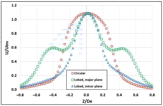
Figure 4.
Normalized mean streamwise velocity profiles at the jet exit for hemispherical nozzles.
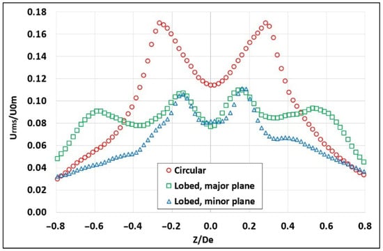
Figure 5.
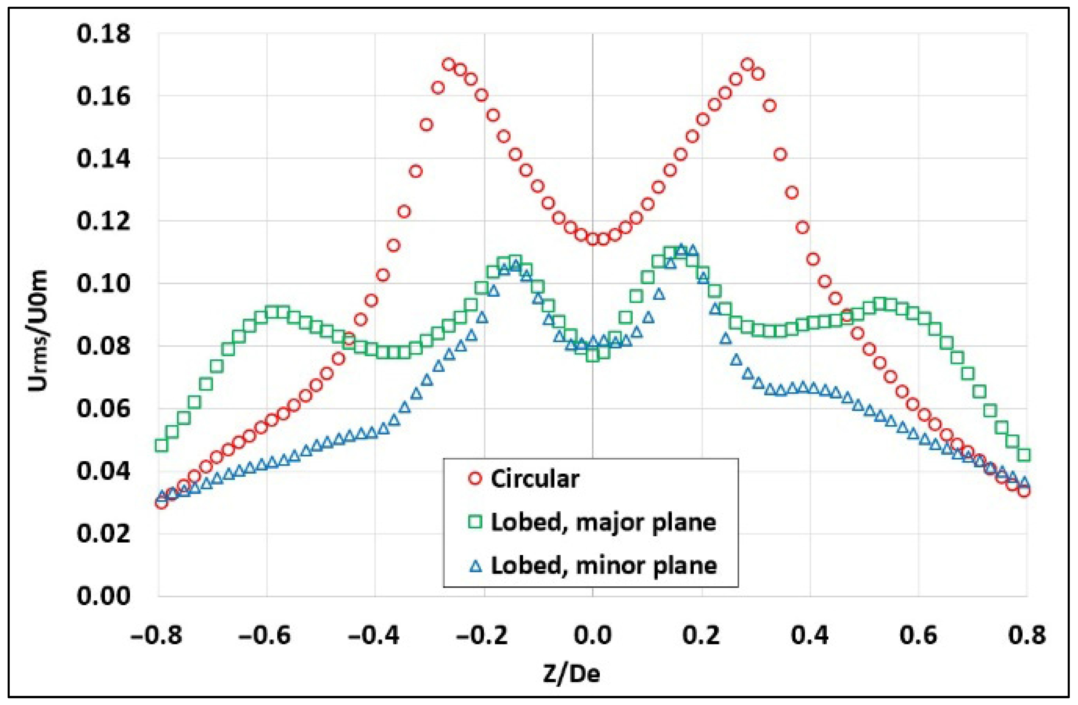
Normalized turbulence intensity profiles at the jet exit for hemispherical nozzles.
In comparison, El Hassan and Meslem [3] used 2D planar orifices in their TR-PIV jet investigations. A “saddle-backed” shape of the average streamwise velocity profiles for the circular jet and the minor plane of the lobed jet was observed. Whereas, an “M” shape was observed for the major plane of the lobed jet. Krueger [32] reported similar observations, at a jet planar exit. Moreover, El Hassan and Meslem [3] observed the “vena-contracta” effect due to significant increases in velocity at the exit edges of the planar orifices’ jets. Qunin et al. [33] and Ashforth et al. [34] observed similar behavior.
Figure 5 shows the turbulent intensity profiles where no flat regions are observed for both types of jets (circular and lobed). This indicates the start of high turbulence levels not only at edges where local shear is expected to be high but also along the entire axial span of jet cross-planes. Such behavior might lead to higher entrainment rates and thus better mixing phenomena in the near-field regions of the jets, with higher expected values for the lobed jet.
The broader turbulence intensity peaks in the circular jet indicate stronger radial spreading compared to the lobed jets. This is due to the absence of geometric modulation in the circular nozzle, which leads to more uniform azimuthal shear layer development and earlier roll-up of Kelvin–Helmholtz instabilities. This can also lead to the higher turbulence intensity peaks observed in the circular jet. In contrast, the lobed nozzles generate streamwise vortices that enhance axial entrainment and mixing, particularly in the minor plane. This results in narrower turbulence intensity around the double peak, as shown in Figure 5.
Furthermore, higher values of turbulence intensity were observed for hemispherical nozzle ranges between 3 and 17% for the circular jet and 3 and 11% for the lobed jet compared to ranges between 0 and 6%, which were observed for planar orifice circular jets and between 0 and 14% for planar orifice lobed jets [3]. In addition, at the jets’ edges, significantly higher RMS values were observed in the central regions of all 3D hemispherical jets compared to 2D planar ones.
In comparison, El Hassan and Meslem [3] demonstrated that the turbulent intensity profile remains flat at approximately 2% in the center of the circular jet as well as for both the minor and major planes of the lobed jet. However, in the regions of the shear layer (jet edges), the RMS values increase in both planar jets (6%, 14%, and 11% for the circular jet, minor plane, and major plane of the lobed jet, respectively). The authors [3] expected such high RMS values in regions where the local shear in the average streamwise velocity is high.
3.2. Mean Velocity Fields
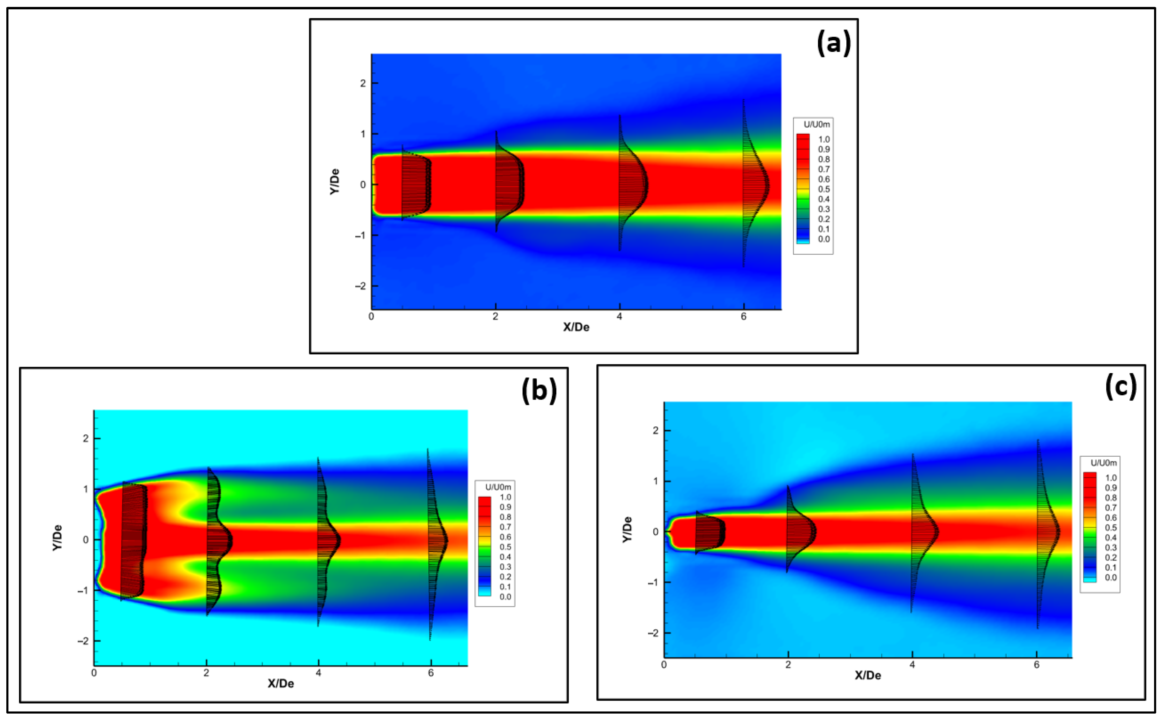
To analyze the streamwise evolution of jet flow downstream from both circular and six-lobed hemispherical nozzles, two-dimensional (2D) PIV measurements were performed in the center plane. The two-component (2C) of the streamwise velocity profiles is presented at several cross-plane longitudinal locations in Figure 6 over the range of 0 ≤ X/De ≤ 6.5 for both hemispherical jets by averaging 500 instantaneous PIV images. It should be noted that both the iso-contours and the vector representations of the velocity are presented in Figure 6. The velocity profiles in the two planes converge and appear nearly identical after X/De = 6.
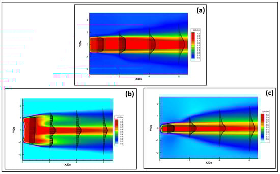
Figure 6.
Mean streamwise velocity profiles for hemispherical nozzle jets; (a) circular; (b) lobed major plane; (c) lobed minor plane.
Figure 6a shows the mean streamwise velocity profiles obtained for the circular hemispherical nozzle jet. At X/De = 0.5, it is observed that the velocity profile maintains a flat shape in the jet core region. This could be related to a larger span of turbulence fluctuations providing higher rates of mixing by entrainment. In comparison, for the circular planar orifice, El Hassan and Meslem [3] reported that velocity profiles become almost flat at X/De = 0.5 in the jet core region compared to those measured at the jet exit. These profiles keep changing their shapes while traveling downstream along the jet shear layer, with a quicker transition observed in the lobed jet. In the major plane of the hemispherical nozzle lobed jet (Figure 6b), we observed the presence of a stronger two-step distribution in the mean velocity profiles for several longitudinal locations along the jet core. However, the two-step profile is almost absent in the minor plan (Figure 6c). Nastase and Meslem [9] and Hu et al. [9,35] observed the same behavior in their studies of velocity profiles downstream of a lobed nozzle jet.
In comparison, for the major plane of the planar orifice lobed jet, the authors [3] observed the presence of a two-step distribution in the average velocity profiles for several longitudinal locations along which the jet core was observed. Nevertheless, both distributions were compared to confirm that the “2-step” distribution is stronger in the hemispherical jets introducing higher levels of turbulence as well as entrainment rates and leading to better mixing behavior compared to planar orifice jets.
3.3. Entrainment Mechanism
The entrainment is defined as the streamwise spatial derivative of the volume flux Q(x), i.e., dQ/dx [3]. The net volume flux in the longitudinal direction (X/De) is balanced by the volume flux in the radial direction (r/De). Therefore, to obtain the entrainment rate, Equation (1) [3] is used.
where is the initial volumetric flow rate, is the volumetric flow rate at the longitudinal distance (X/De) from the jet exit plane, De is the jet equivalent diameter, r is the radial distance (r/De), and is the radial velocity.
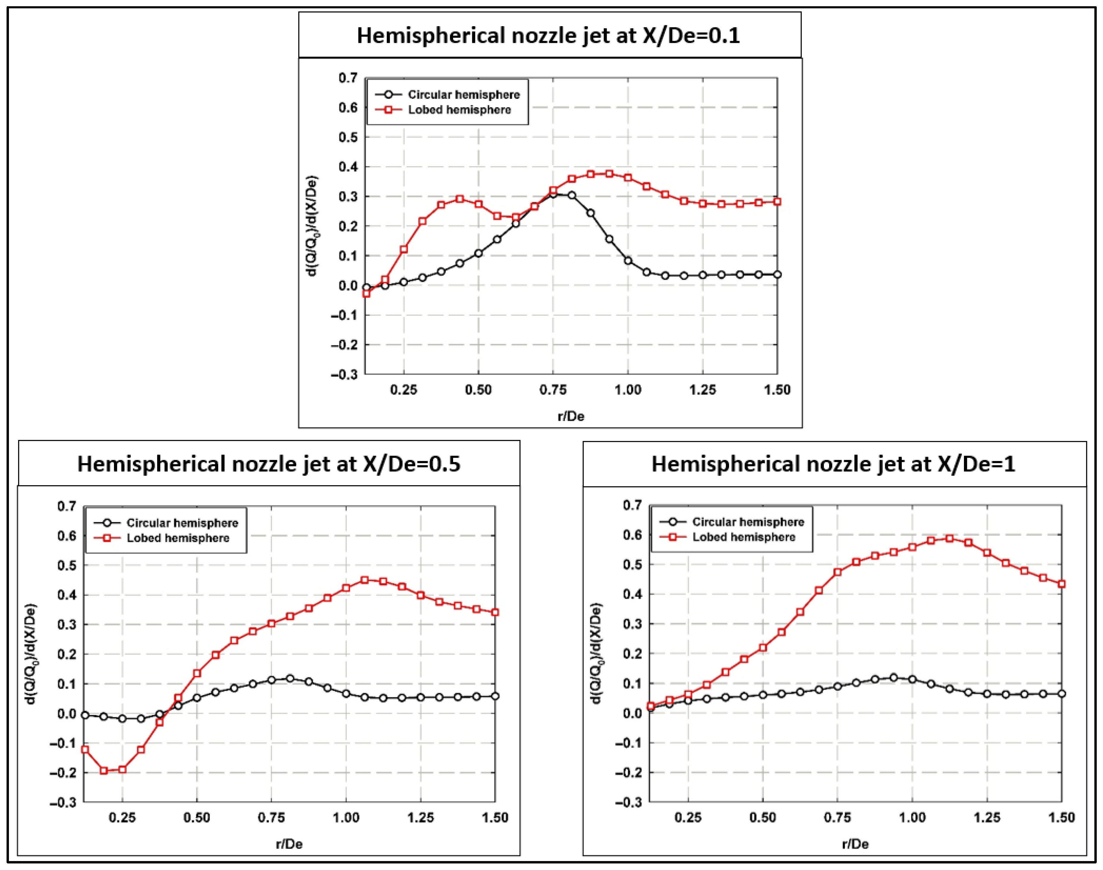
Figure 7 shows the dependence of the normalized average volume flux (average entrainment rate) on the radial distance (r/De) for different streamwise longitudinal locations. It is seen that a strong dependence of the radial volume flux is present in the hemispherical lobed jets within the initial near-field region for X/De ≤ 1. For the hemispherical circular jets, the spatial dependency is mainly observed near the jet exit (X/De = 0.1), then it almost stabilizes (plateau behavior with slight positive values) for X/D = 0.5 and 1.

Figure 7.
Normalized average radial volume flux at different longitudinal locations for both hemispherical nozzle jets.
By analyzing the radial spatial dependency of the average volume flux, higher positive values of entrainment were observed by the hemispherical jets presented in this work compared to the planar orifice jets [3]. It is worth mentioning that the positive values of the radial volume flux indicate the entrainment process of the surrounding fluid toward the core (center) of the jet, while negative values are explained as a jet flow expansion away from its center.
Figure 7 also indicates that the effect of the lobed jet extends further radially as compared to the circular jet. Such analysis helps with choosing a proper integration radius for the calculation of the entrainment rate for both jets. These fluctuations are more pronounced for the hemispherical lobed nozzle jet compared to the circular nozzle jet. This indicates that the lobed geometry enhances mixing and entrainment mechanisms, leading to greater variability in the radial flow field. Additionally, the increased radial reach of the lobed jet highlights its ability to extend entrainment effects further from the jet centerline, making it more effective for applications requiring broader mixing.
Furthermore, by analyzing Figure 7 and depending on the distance, almost double the positive entrainment rates are observed for the hemispherical nozzle lobed jets compared to planar lobed orifice jets [3]. In other words, twice the absolute values of entrainment rates’ fluctuations are observed. All of the above-mentioned interesting observations indicate higher potential rates of efficient mixing phenomena in the near-field regions of jet flows utilizing the hemispherical nozzle geometries as one of the passive control methods of mixing processes. Moreover, for hemispherical jets, another interesting observation is that no negative values were observed, i.e., negligible rates of jet flow expansions. This indicates higher positive entrainment rates that lead to better mixing phenomena in the near-field regions of the jets.
Figure 7 also shows that the lobed nozzle jet sustains a greater volume flux peak, reflecting this jet’s ability to promote more vigorous mixing and entrainment at midstream locations, consistent with Zaman (1999) [36]. For X/De = 1, circular nozzle continues to exhibit weaker radial flux and limited mixing, whereas the lobed nozzle retains its strong radial volume flux, sustaining turbulence and enhanced entrainment downstream, also noted by Mi et al. (2001) [37]. The lobed nozzle consistently excels the circular one in generating radial spreading and turbulence, critical for rapid mixing applications, e.g., combustion or chemical processing.
Quantitative investigations of the S-W vorticity evolution are presented in order to better understand and relate jets’ evolution with the evolved entrainment process. The effect of different S-W structures on mixing enhancement can be quantified by computing the averaged ( and maximum () S-W vorticity in the longitudinal direction.
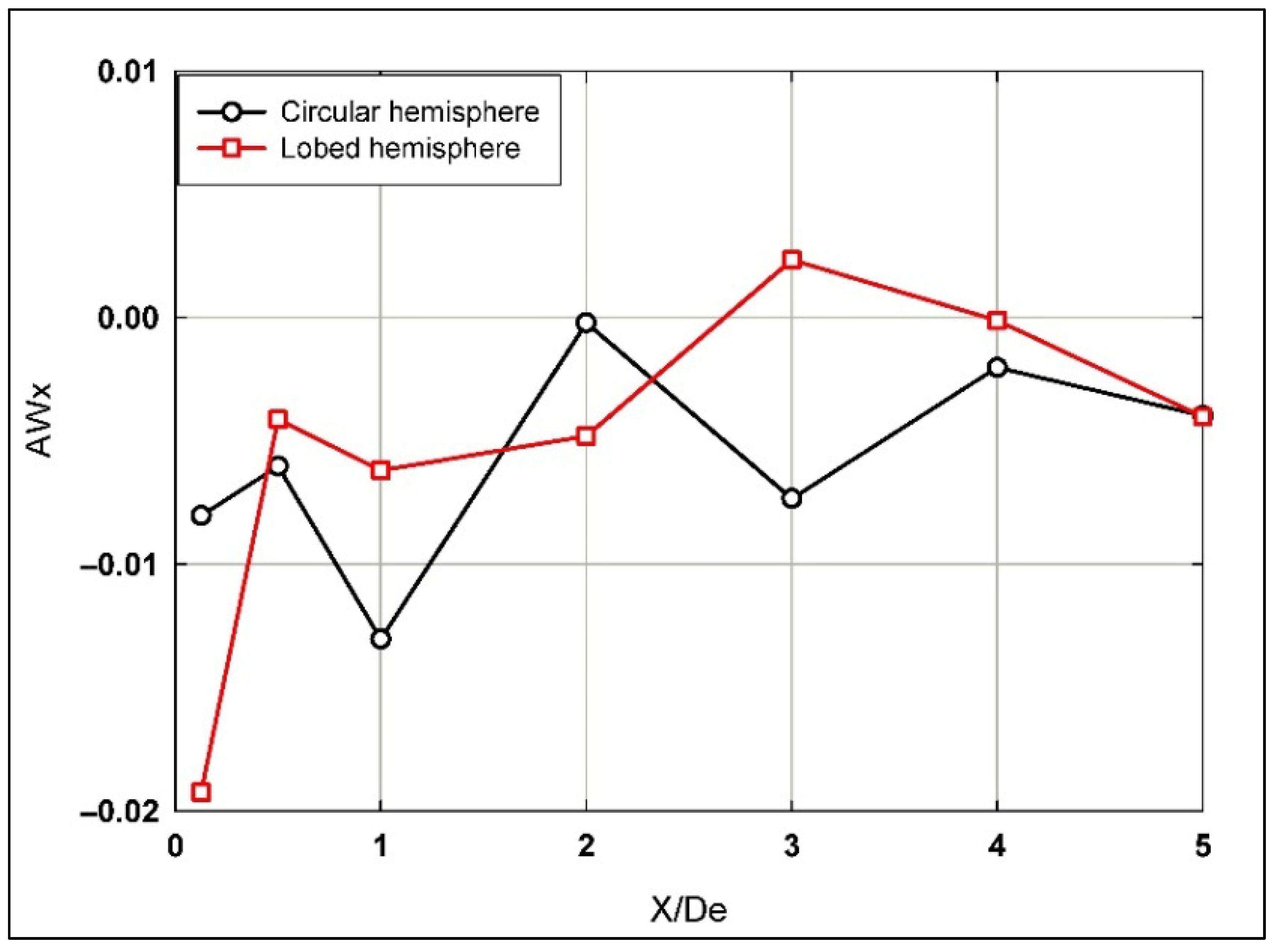
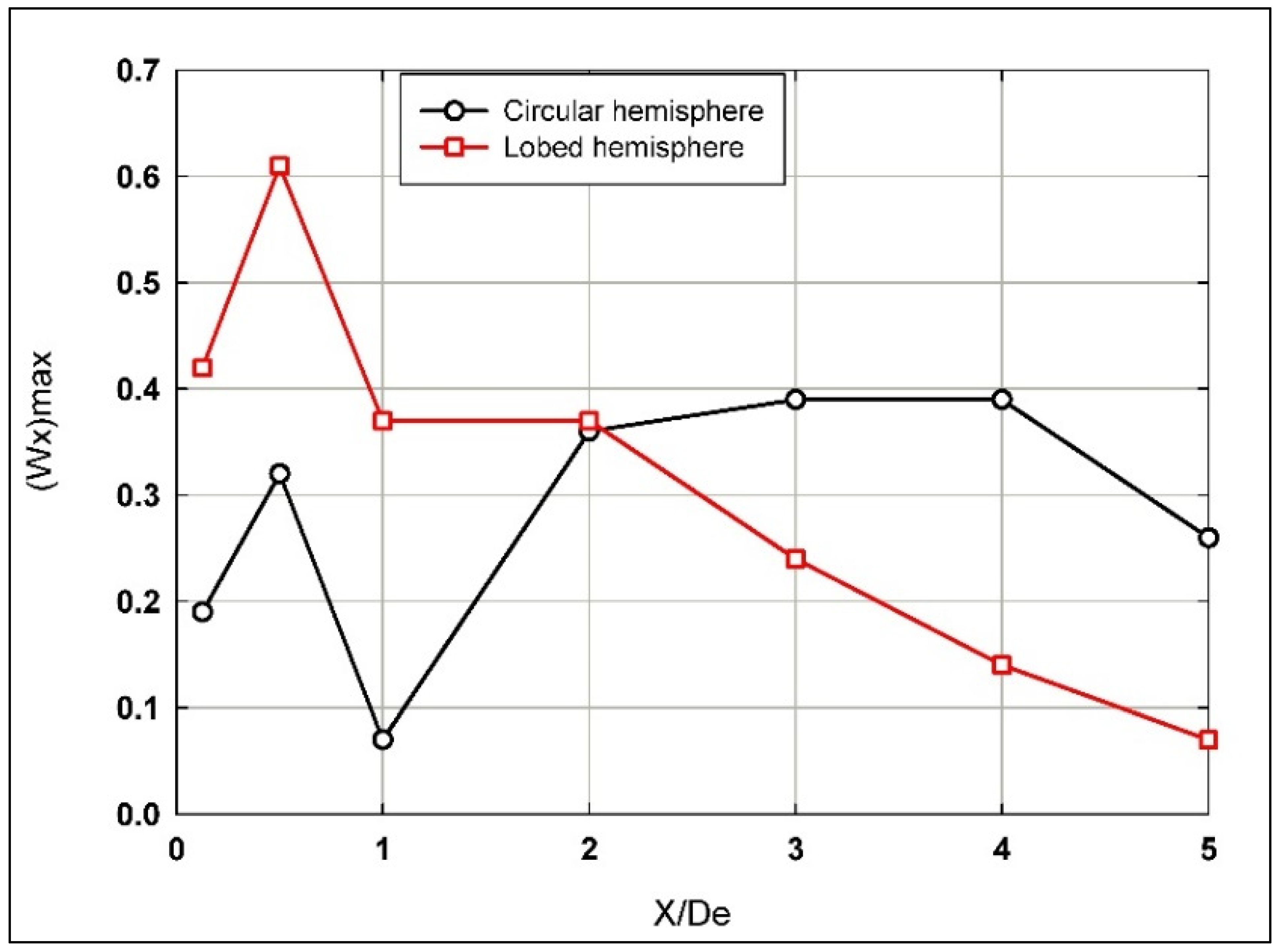
Figure 8 and Figure 9 show a detailed analysis of the S-W averaged ) and maximum () vorticity distributions, respectively, for both circular and lobed hemispherical jets compared along the longitudinal direction of the jets’ flow. It can be observed that, for both investigated jets, values fluctuate along the entire span in the longitudinal direction (0 ≤ X/De ≤ 5) with slightly greater values for the lobed jet for most streamwise locations. For values, higher values are observed for the lobed jet when compared to the circular jet for 0 ≤ X/De ≤ 2, whereas the situation is inverted further downstream, as greater values were observed for the circular jet.
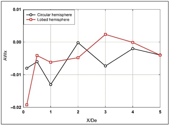
Figure 8.
Averaged streamwise vorticity distribution along the longitudinal direction for both hemispherical nozzle jets.

Figure 9.
Maximum streamwise vorticity distribution along the longitudinal direction for both hemispherical nozzle jets.
Additionally, from Figure 8, it is observed that the lobed nozzle shows higher values of ) at the jet exit, indicating stronger initial vorticity generation compared to the circular nozzle. As X/De increases, the lobed nozzle demonstrates more significant oscillations in vorticity up to X/De = 3, which reflects enhanced mixing and periodic vortex shedding. Beyond X/De = 3, the vorticity values for both nozzles converge, indicating that the turbulence decays with downstream distance. This behavior aligns with the findings of Gutmark and Grinstein (1999) [38], who observed that lobed nozzles generate higher turbulence levels at the early stages of jet development.
In comparison, El Hassan and Meslem [3] reported that when planar orifice jets flow from X/De = 1 to 3, the S-W vorticity continued intensifying gradually for the circular jet while it decayed for the lobed jet. That was attributed to the growth of the vortices in the longitudinal direction, which heavily contributes to the entrainment process while moving downstream from the jet exit. For the distributions of the averaged and maximum S-W vorticity for planar jets, it was reported that higher values were observed for the lobed mixing jet compared to the circular one within 0 ≤ X/De ≤ 3. Whereas, the situation is inverted afterward, as greater values were observed for the circular jet. On the other hand, a decrease in the values was observed as X/De increased for the planar orifice lobed jet. Eckerle et al. [39] and Werle et al. [40] related this behavior to a breakdown of the large-scale S-W vortices into many small-scale ones.
Negative averaged S-W vorticity values imply that the jet flows are decelerating in those regions of observation (i.e., the S-W velocity vectors are rotating opposite to flow direction). This might complicate the flow dynamics, or it can be attributed to a “vortex shedding” phenomenon. It is also worth emphasizing that, eventually, the understanding of the flow dynamics depends on the balance of all relevant flow phenomena in the region of interest of the application being investigated. Therefore, further detailed analysis of flow dynamics is still required to accurately assess such effects on the mixing phenomena by entrainment.
From Figure 9, it is observed that the lobed nozzle exhibits significantly higher peak values near the jet exit (X/De ≈ 0.5), with a gradual decline as X/De increases. The circular nozzle, in contrast, shows a more modest increase in vorticity, with irregular fluctuations along the jet’s length. This suggests that the lobed nozzle promotes stronger coherent streamwise vortical structures, which enhance entrainment and mixing, particularly in the early and midstream regions.
It is observed from Figure 9 that the development of the S-W vortices becomes more significant for the circular jet between X/De = 2 and 4, indicating a stronger growth of vortices in that region. This supports more prolonged, coherent vortex structures, which can lead to less efficient mixing. However, beyond this point, the strength of these vortices starts to decay. For the lobed nozzle jet, the decay starts directly from X/De = 2, indicating the disruption of the coherence of the vortices earlier, likely due to enhanced shear layer interactions and increased mixing efficiency introduced by the lobes. After X/De = 4, both jets decay, with higher values for the circular hemispherical nozzle jet.
The cross-plane distributions of the Turbulent Kinetic Energy (TKE) are used to compare the flow evolution of both jets along the axial downstream distance [3]. Hu et al. [35] proposed to study the Averaged Turbulent Kinetic Energy (ATKE). It can be calculated at any selected longitudinal cross-plane location using Equation (2) [6], as follows:
where K is the Turbulent Kinetic Energy calculated from the three components of the velocity obtained from stereoscopic TR-PIV measurements using Equation (3) [6], as follows:
where RMS values are the three root-mean-squared components in the (x, y, z) directions, respectively; N = 500 is the number of instantaneous TR-PIV images used in the averaging calculation for the streamwise velocities; and (u, v, w) are the three instantaneous velocity components (3C) in the (x, y, z) directions (3D), respectively.
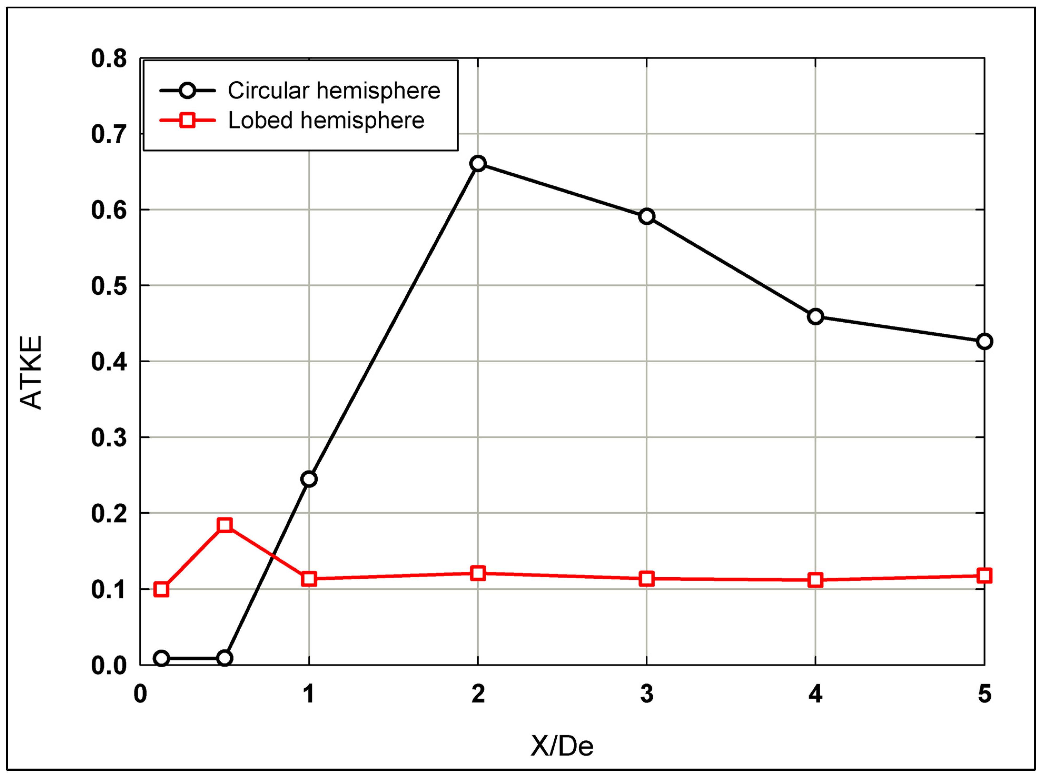
The distribution of the Averaged Turbulent Kinetic Energy (ATKE) for hemispherical nozzle jets is presented in Figure 10, comparing circular and lobed jet configurations. Close to the nozzle exit (0.1 ≤ X/De ≤ 0.5), the lobed jet exhibits significantly higher ATKE values than the circular jet, due to the nozzle geometry itself, which inherently enhances mixing in the near-field region. Beyond X/De = 0.5, the behavior diverges: the lobed jet maintains a relatively flat ATKE profile across the flow span, persisting downstream after X/De = 1. This consistent ATKE profile suggests that the lobes are effective in maintaining mixing efficiency over a longer distance further downstream. In contrast, the circular jet demonstrates a rapid increase in ATKE between X/De = 0.5 and X/De = 2, attributed to the significant K–H instability, suggesting intensified mixing activity in this region. This is followed by a gradual decline as the jet transitions further downstream.
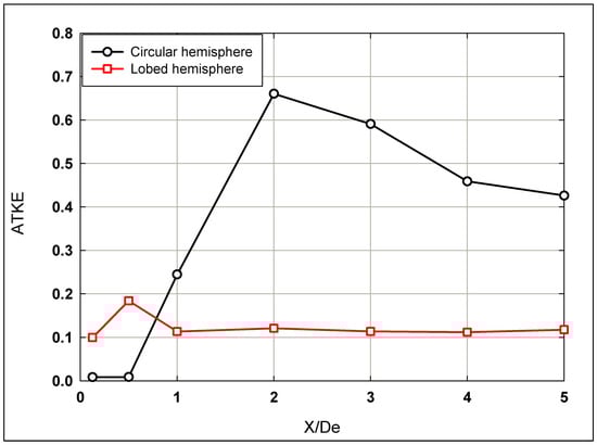
Figure 10.
The ATKE distribution along the longitudinal direction for both hemispherical nozzle jets.
Furthermore, as can be inferred from Figure 10, higher ATKE can be a disadvantage for many industrial applications. Thus, the lobed jet presents the advantage of lower TKE and much higher entrainment and mixing. Thus, less noise and drag would arise from the lobed jet.
In comparison, El Hassan and Meslem [3] observed that, for the circular orifice jet, ATKE rapidly increases within 0 ≤ X/De ≤ 3, then stabilizes. For the lobed orifice jet, ATKE decreases within 0 ≤ X/De ≤ 1 and then rapidly increases within 1 ≤ X/De ≤ 2.5 until plateauing. Near the jet exit (X/De ≤ 0.7), ATKE values are lower for the circular orifice jet compared to the lobed one but become higher downstream in the longitudinal S-W direction due to the pairing of the K–H structures. According to the “collective interaction mechanism” [41], small vortices roll up to form K–H structures. Ho and Nosseir [42] noted that vortices coalesce into large vortices due to the induced field. The axis-switching phenomena and flow convergence observed further downstream contribute to decreased ATKE values within 0.5 ≤ X/De ≤ 1. The high energetic level of S-W vortices in the lobed jet explains higher ATKE values near the exit compared to the circular jet. Additionally, azimuthal modes could compete with each other for growth of the shear layer [43].
3.4. Shear Layer Growth
The shear layer growth is a measure of the momentum entrained into the shear layer [44] and is calculated using Equation (4) [6], as follows:
where U1 and U2 are the velocities of the two streams at the inlet of the mixing region, U is the local ensemble averaged velocity, and U0m is the centerline exit longitudinal velocity of air obtained from PIV measurements at X/De = 0.1. In the present study, U2 = 0 and U1 = U0m. Figure 11 shows the normalized shear layer growth in terms of the momentum thickness along the longitudinal direction reflecting the distribution of momentum across that layer. For the hemispherical circular nozzle jet, it is observed that the rate of shear layer growth decreases near the nozzle until reaching X/De = 1, then it rapidly increases downstream of the nozzle to the end of investigated longitudinal span due to the mixing between the air jet and the surrounding fluid. This indicates a slower rate of expansion of the shear layer and thus less mixing in this region. As the jet progresses, increased mixing between the air jet and surrounding occurs. In contrast, for hemispherical lobed nozzle jets, the rate of shear layer growth increases near the nozzle till reaching X/De = 2 then stabilizes to the end of investigated longitudinal span. It indicates enhanced mixing right from the lobed nozzle exit, leading to a sustained growth in the shear layer.
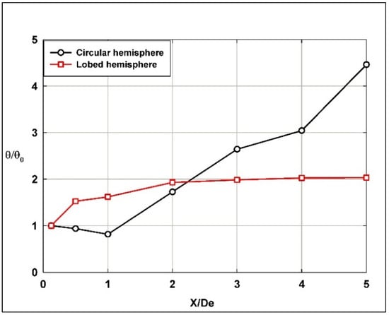
Figure 11.
The normalized shear layer growth in terms of the momentum thickness along the longitudinal direction for both hemispherical nozzle jets.
In light of the passive-control mechanisms of jets’ flows, these observations present various behaviors where applications determine the choice between hemispherical circular or lobed nozzles, which can be optimized based on the desired shear layer behavior. For instance, the hemispherical lobed nozzles might be more effective in applications where rapid (early stages) mixing is desired right at the nozzle exit, while hemispherical circular nozzles may be preferable where initial flow stability is more critical, i.e., late-stage mixing is preferred.
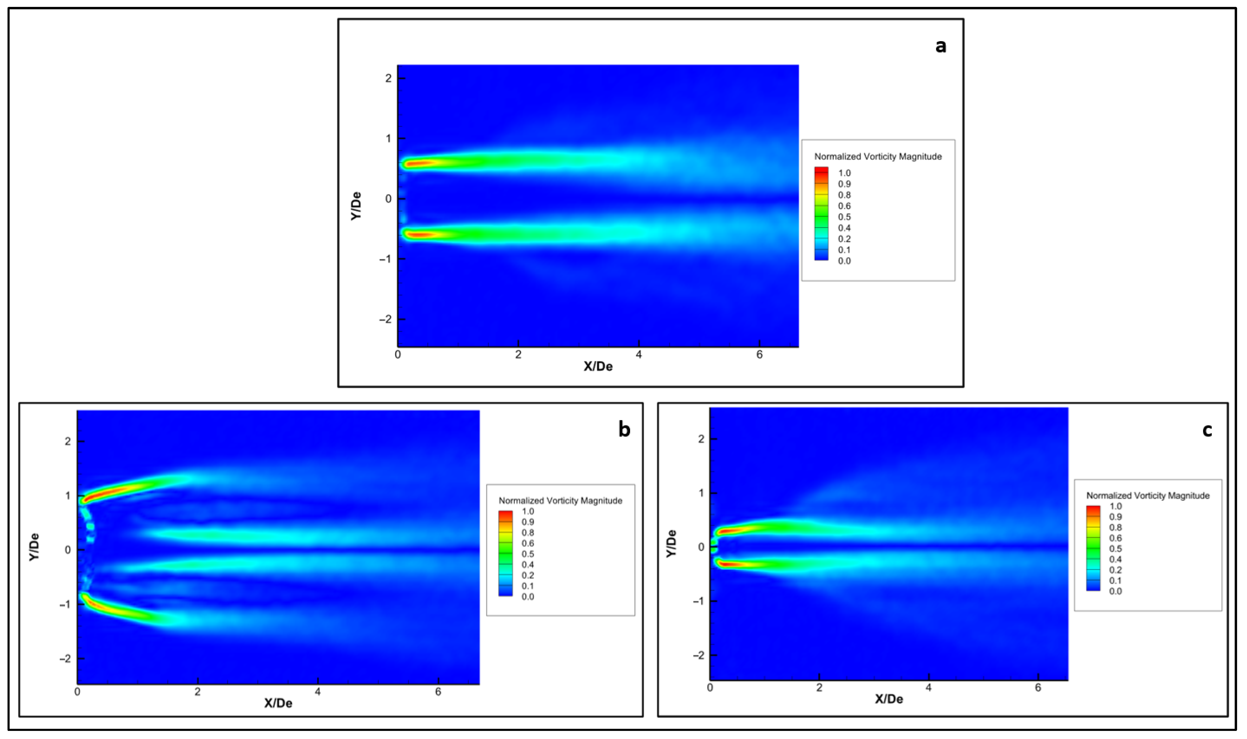
Figure 12 visualizes the normalized distribution in the longitudinal plan of the circular and lobed jets. This distribution highlights distinct regions of high vorticity, which correspond to locations of strong shear within the flow. These regions are indicative of the formation and interaction of vortices in the shear layer. Figure 12a shows that the vorticity is concentrated near the centerline, suggesting a more symmetrical flow pattern. Figure 12b exhibits a more complex flow pattern with distinct regions of higher vorticity, indicating increased turbulence and mixing. The flow is less symmetrical, displaying more complex interactions within the fluid. Figure 12c demonstrates a different flow behavior with variations in the vorticity magnitude distribution indicating a flow pattern in the minor plan that confirms the fast-mixing rate in both the major and minor plans up to X/De = 2.
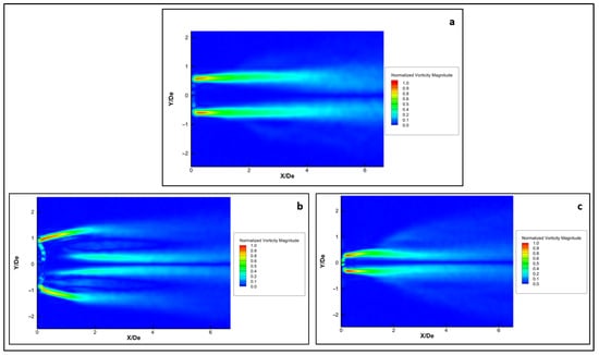
Figure 12.
Normalized vorticity showing flow behavior within the shear layer along the longitudinal direction for the hemispherical nozzle jets; (a) circular; (b) lobed major plane; (c) lobed minor plane.
The normalized vorticity magnitude, that which is more concentrated near the nozzle exit in both investigated jets, suggests stronger vortex formation closer to the origin of jets. Higher values near the nozzle exit suggest more intense mixing and momentum transfer, leading to higher entrainment rates in the near-field region.
3.5. Momentum Flux Distribution
To obtain the conservation equations for the volume flux and axial momentum, the continuity and axial momentum equations, respectively, can be integrated across the jet [45]. The kinematic momentum flux M(x) can be obtained by integrating the axial momentum equation as follows using Equation (5) [3]:
where is the mean streamwise velocity, and are the contributions from the velocity fluctuations and mean pressure, respectively, and S is the jet surface in the cross-plane.
For many years, it was believed that the momentum flux in any jet is very nearly constant [46,47]. Kotsovinos [48,49] challenged the assumption that momentum flux is constant along the jet’s path and showed that it varies due to external factors like entrainment, jet geometry, and pressure fields. Self-preservation in jets, while widely accepted, is only achievable if the source is considered a point source of momentum. Laboratory jets, however, cannot replicate this idealized point source.
Miller and Comings [50] and Bradbury [51], in their experimental studies, proposed that the contributions from the velocity fluctuations (turbulences) and mean static pressure to the kinematic momentum flux M(x) are negligible. In addition, the S-W pressure gradient was replaced by the radial momentum equation as suggested by Hussein et al. [52] and as follows using Equation (6) [6] to obtain M(x):
In this paper, the kinematic momentum flux (momentum integral), M(x), was estimated from the average axial velocity PIV measurements. Theoretically, the longitudinal turbulences contribute to M(x) can be defined using Equation (7) [3,6], as follows:
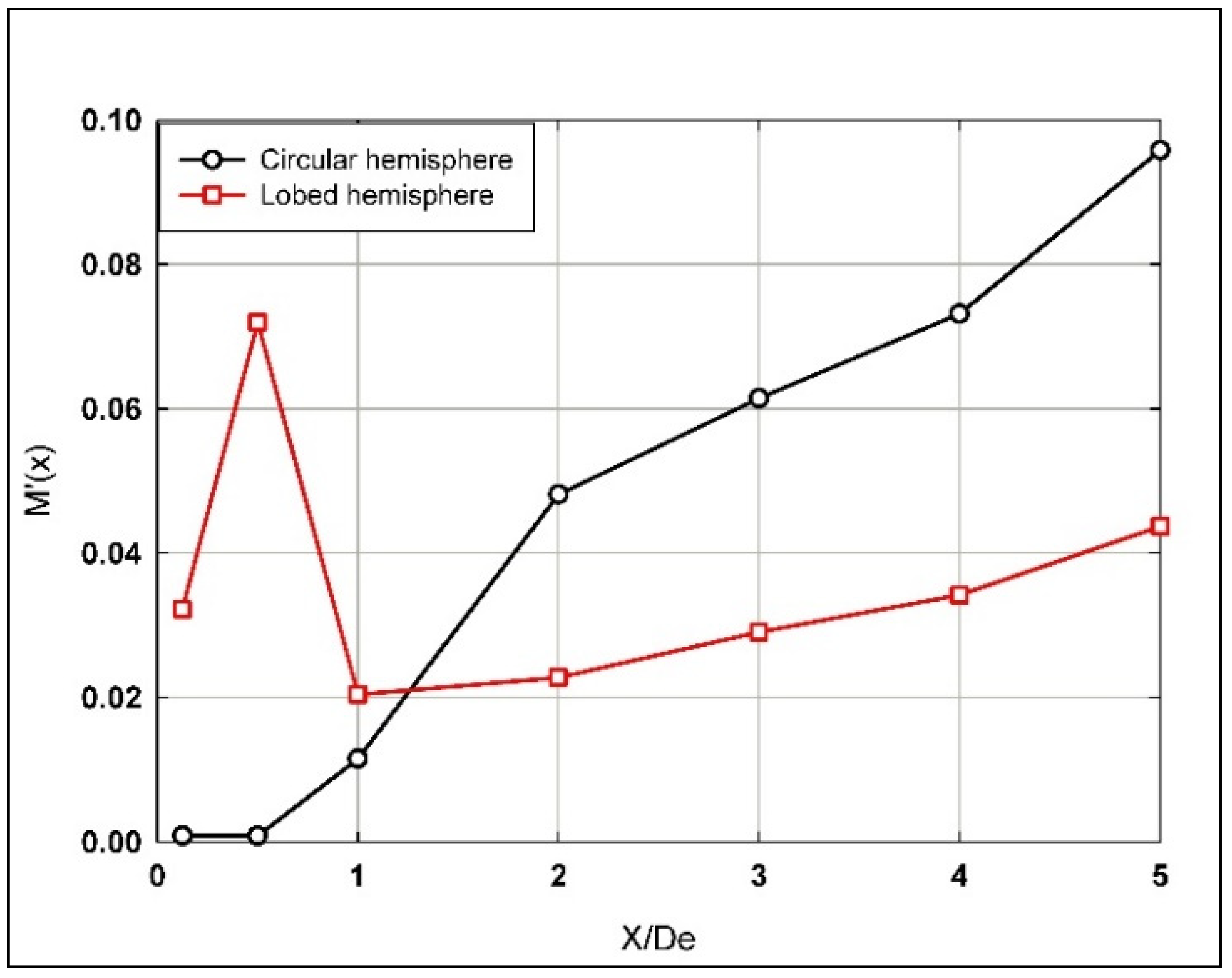
Figure 13 proves that the contribution from the S-W turbulence intensity to the momentum flux in the initial region of both the hemispherical circular and the six-lobed jet flows should not be neglected. Indeed, this contribution is considerable for the hemispherical lobed nozzle jet flow ranging between 2 and 7% at early stages of the near-field region up to X/De = 1 and is lower for the hemispherical circular nozzle jet up to 1% in the same mentioned region. However, after X/De = 1, the situations change significantly, where for the hemispherical lobed nozzle jet flow, a gradual increase in the momentum flux (Figure 13) ranged between 2 and 4% till the end of the investigated longitudinal span. Whereas, for the hemispherical circular nozzle jet flow, a rapid increase was observed, reaching up to 10% at X/De = 5.
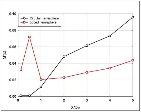
Figure 13.
Contribution from the streamwise turbulence intensity to the momentum flux along the longitudinal jet flow direction using the hemispherical nozzles.
In comparison, El Hassan and Meslem [3] reported similar behavior (and values) to that of the hemispherical circular nozzle jet upstream along the entire investigated range for the case of planar circular orifice jet. However, for the lobed nozzle jet, the flow behavior diverges significantly between the hemispherical nozzle jets and planar lobed orifice jets just prior to X/De = 1, though the flow characteristics for both geometries align similarly along the remainder of the investigated longitudinal jet flow span.
Figure 14 shows a rapid increase in the normalized momentum flux (up to ratio of 2.5) when traveling downstream along the hemispherical lobed nozzle jet shear layer from the nozzle near exit to X/De = 1, while it remains almost constant (below ratio of 1.25) for the hemispherical circular nozzle jet along the entire investigated longitudinal span. This indicates a more uniform momentum distribution along the jet’s flow span, with less pronounced mixing and momentum transfer, compared to the lobed nozzle. However, for the hemispherical lobed nozzle jet and after X/De = 1, the normalized momentum flux continues to significantly increase up to a ratio of 3.5, then stabilizes to the end of the investigated longitudinal span of the jet flow.
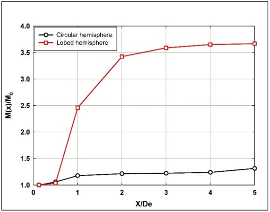
Figure 14.
Normalized momentum flux along the longitudinal jet flow direction using hemispherical nozzles.
The behavior of the hemispherical lobed nozzle jet enhances the jet’s momentum transfer, likely due to increased mixing and turbulence generated by the lobed geometry. With further growth and stabilization beyond X/De = 1, the momentum flux continues to grow, peaking at around 3.5 before stabilizing. This sustained increase indicates that the lobed nozzle continues to promote strong momentum exchange further downstream, contributing to efficient mixing over a larger distance.
In comparison, El Hassan and Meslem [3] reported that the normalized momentum fluxes behavior of the planar orifice circular jet is almost the same as for the hemispherical circular nozzle jet along the entire flow span. However, the normalized momentum flux for hemispherical lobed nozzle jets is almost 100% higher than that of the planar orifice jets. Generally, the increase in the momentum flux for lobed nozzle jets was previously observed and indicated in many studies in the literature [6].
4. Conclusions
More efficient and faster mixing processes in the near-field region of jets with their surrounding fluid are of high interest in many advanced engineering industrial applications. One of the mixing-control strategies known as “passive” involves jet exit (nozzle) geometry modifications different from the traditional circular design, which is discussed. High-speed Time-Resolved Particle Image Velocimetry (TR-PIV) measurements are helpful to experimentally characterize the entrainment mechanism. The entrainment of surrounding fluid by the primary jet flow plays a significant role in improving mixing processes. An analysis of the mean entrainment behavior of air jet flows utilizing a 3D newly proposed innovative hemispherical nozzle (circular and six-lobed) jets is presented. The entrainment rates utilizing these hemispherical nozzles are quantified and described. The distributions of the mean streamwise velocity field, mean entrainment rates, shear layer growth, and momentum flux along the longitudinal direction within the near-field region of a turbulent jet regime are investigated. Various mixing enhancements by entrainment based on a passive-control method using the geometry of a 3D jet exit/nozzle are observed. By comparing both investigated hemispherical nozzle geometries, it has been demonstrated that the lobed nozzle provides higher mixing rates compared to the circular jet. This enhancement in mixing can be attributed to the stronger streamwise vortex structures generated by the lobed nozzle geometry, which promote increased entrainment of the surrounding fluid. The hemispherical lobed nozzles might be more effective in applications where rapid (early stages) mixing is desired right at the nozzle exit, while hemispherical circular nozzles may be preferable where initial flow stability is more critical, i.e., late stages mixing is preferred.
Author Contributions
Conceptualization, M.E.H., A.S. and K.A.-M.; methodology, M.E.H.; software, M.E.H. and N.B.; validation, S.A. and M.E.H.; formal analysis, S.A., M.E.H. and N.B.; investigation, S.A. and M.E.H.; resources and data curation, M.E.H.; writing—original draft preparation, S.A., M.E.H. and N.B.; writing—review and editing, S.A., M.E.H., N.B, A.S. and K.A.-M., visualization, S.A., M.E.H. and N.B.; supervision, M.E.H., A.S. and K.A.-M.; project administration, M.E.H., A.S. and K.A.-M. All authors have read and agreed to the published version of the manuscript.
Funding
This research received no external funding.
Data Availability Statement
The original contributions presented in the study are included in the article, further inquiries can be directed to the corresponding author.
Conflicts of Interest
The authors declare no conflict of interest.
References
- Ho, C.-M.; Gutmark, E. Vortex induction and mass entrainment in a small-aspect-ratio elliptic jet. J. Fluid Mech. 1987, 179, 383–405. [Google Scholar] [CrossRef]
- Austin, T. The Small Scale Topology of a 2:1 Aspect-Ratio Elliptic Jet. Ph.D. Thesis, University of South California, Los Angeles, CA, USA, 1992. [Google Scholar]
- El Hassan, M.; Meslem, A. Time-resolved stereoscopic particle image velocimetry investigation of the entrainment in the near field of circular and daisy-shaped orifice jets. Phys. Fluids 2010, 22, 035107. [Google Scholar] [CrossRef]
- Hashiehbaf, A.; Romano, G. Particle image velocimetry investigation on mixing enhancement of non-circular sharp edge nozzles. Int. J. Heat Fluid Flow 2013, 44, 208–221. [Google Scholar] [CrossRef]
- Nastase, I.; Meslem, A.; El Hassan, M. Image processing analysis of vortex dynamics of lobed jets from three-dimensional diffusers. Fluid Dyn. Res. 2011, 43, 065502. [Google Scholar] [CrossRef]
- El Hassan, M.; Meslem, A.; Abed-Meraim, K. Experimental investigation of the flow in the near-field of a cross-shaped orifice jet. Phys. Fluids 2011, 23, 045101. [Google Scholar] [CrossRef]
- Paizis, S.T.; Schwarz, W.H. Entrainment rates in turbulent shear flows. J. Fluid Mech. 1975, 68, 297–308. [Google Scholar] [CrossRef]
- Sodjavi, K.; Montagné, B.; Meslem, A.; Byrne, P.; Serres, L.; Sobolik, V. Passive control of wall shear stress and mass transfer generated by submerged lobed impinging jet. Heat Mass Transf. 2015, 52, 925–936. [Google Scholar] [CrossRef]
- Nastase, Analyse des Jets Lobés en vue de Leur Intégration Dans les Unités Terminales de Diffusion d’air. Ph.D. Thesis, Université de La Rochelle, La Rochelle, France, 2007.
- Nastase, I.; Meslem, A. Vortex dynamics and mass entrainment in turbulent lobed jets with and without lobe deflection angles. Exp. Fluids 2010, 48, 693–714. [Google Scholar] [CrossRef]
- Nastase, I.; Meslem, A.; Gervais, P. Primary and secondary vortical structures contribution in the entrainment of low Reynolds number jet flows. Exp. Fluids 2008, 44, 1027–1033. [Google Scholar] [CrossRef]
- Bode, F.I.; Dogeanu, A.; Tăcutu, L.; Nastase, I.; Danca, P.A.; Angelescu, A.E. Experimental study of an innovative perforated air diffuser at real scale conditions. Energy Rep. 2022, 8, 1479–1490. [Google Scholar] [CrossRef]
- Kannan, B.; Ssheshan, P.; Senthilkumar, S. Large Eddy Simulation of isothermal cruciform jet flow: Preliminary results. Perspect. Sci. 2016, 8, 10–12. [Google Scholar] [CrossRef]
- Myeong, J.; Kim, S.; Kim, D.; Kim, J.; Shin, W.G. The effect of the nozzle exit geometry on the flow characteristics of the free condensing jet. Nucl. Eng. Technol. 2024, 56, 2545–2556. [Google Scholar] [CrossRef]
- Seif, A.; Zedan, M.; Shibl, A. Effect of nozzle exit geometry on the development of turbulent jets. J. King Saud Univ. Eng. Sci. 1994, 6, 217–239. [Google Scholar] [CrossRef]
- Pawlowska, A.; Boguslawski, A.; Tyliszczak, A.; Geurts, B. Dynamics of transitional jets emanating from a non-circular nozzle. Exp. Therm. Fluid Sci. 2022, 139, 110720. [Google Scholar] [CrossRef]
- Sheng, Z.-Q.; Liu, J.-Y.; Yao, Y.; Xu, Y.-H. Mechanisms of lobed jet mixing: About circularly alternating-lobe mixers. Aerosp. Sci. Technol. 2020, 98, 105660. [Google Scholar] [CrossRef]
- Rohn, M.; Mathis, P.; Röder, T.; Müller, D. Stereoscopic particle image velocimetry study of the single side entrainment behaviour of multiple air jets with different nozzle cross-sections. Build. Environ. 2021, 205, 108195. [Google Scholar] [CrossRef]
- Bragança, P.; Sodjavi, K.; Meslem, A.; Nastase, I. Passive control strategy for mixing ventilation in heating mode using lobed inserts. Energy Build. 2016, 133, 512–528. [Google Scholar] [CrossRef]
- Salewski, M.; Stankovic, D.; Fuchs, L. Mixing in circular and non-circular jets in crossflow. Flow Turbul. Combust. 2008, 80, 255–283. [Google Scholar] [CrossRef]
- Rahman, M.S.; Tay, G.F.K.; Tachie, M.F. Effects of nozzle geometry on turbulent characteristics and structure of surface attaching jets. Flow Turbul. Combust. 2019, 103, 797–825. [Google Scholar] [CrossRef]
- Hashiehbaf, A.; Romano, G. Experimental investigation on circular and non-circular synthetic jets issuing from sharp edge orifices. In Proceedings of the 17th International Symposium on Applications of Laser Techniques to Fluid Mechanics, Lisbon, Portugal, 7–10 July 2014. [Google Scholar]
- Bennia, A.; Fellouah, H.; Khelil, A.; Loukarfi, L.; Naji, H. Experiments and Large-Eddy Simulations of Lobed and Swirling Turbulent Thermal Jets for HVAC’s Applications. J. Appl. Fluid Mech. 2020, 13, 103–117. [Google Scholar] [CrossRef]
- Prasad, A.K.; Adrian, R.J. Stereoscopic particle image velocimetry applied to liquid flows. Exp. Fluids 1993, 15, 49–60. [Google Scholar] [CrossRef]
- Arroyo, M.P.; Greated, C.A. Stereoscopic particle image velocimetry. Meas. Sci. Technol. 1991, 2, 1181. [Google Scholar] [CrossRef]
- Sinha, S.K.; Kuhlman, P.S. Investigating the use of stereoscopic particle streak velocimetry for estimating the three-dimensional vorticity field. Exp. Fluids 1988, 12, 377–384. [Google Scholar] [CrossRef]
- Prasad, A.K. Stereoscopic particle image velocimetry. Exp. Fluids 2000, 29, 103. [Google Scholar] [CrossRef]
- Westerweel, J. Digital Particle Image Velocimetry. Ph.D. Thesis, Delft University, Delft, The Netherlands, 1993. [Google Scholar]
- Prasad, A.K.; Adrian, R.J.; Landreth, C.C.; Offutt, P.W. Effect of resolution on the speed and accuracy of particle image velocimetry interrogation. Exp. Fluids 1992, 13, 105–116. [Google Scholar] [CrossRef]
- Lawson, N.J.; Wu, J. Three-dimensional particle image velocimetry: Error analysis of stereoscopic techniques. Meas. Sci. Technol. 1997, 8, 894–900. [Google Scholar] [CrossRef]
- Soloff, S.M.; Adrian, R.J.; Liu, Z.-C. Distortion compensation for generalized stereoscopic particle image velocimetry. Meas. Sci. Technol. 1997, 8, 1441–1454. [Google Scholar] [CrossRef]
- Krueger, P.S. An over-pressure correction to the slug model for vortex ring circulation. J. Fluid Mech. 2005, 545, 427–443. [Google Scholar] [CrossRef]
- Quinn, W. Upstream nozzle shaping effects on near field flow in round turbulent free jets. Eur. J. Mech. B/Fluids 2006, 25, 279–301. [Google Scholar] [CrossRef]
- Ashforth-Frost, S.; Jambunathan, K. Effect of nozzle geometry and semi-confinement on the potential core of a turbulent axisymmetric free jet. Int. Commun. Heat Mass Transf. 1996, 23, 155–162. [Google Scholar] [CrossRef]
- Hu, H.; Saga, T.; Kobayashi, T.; Taniguchi, N. A study on a lobed jet mixing flow by using stereoscopic particle image velocimetry technique. Phys. Fluids 2001, 13, 3425–3441. [Google Scholar] [CrossRef]
- Zaman, K.B.M.Q. Spreading characteristics of compressible jets from nozzles of various geometries. J. Fluid Mech. 1999, 383, 197–228. [Google Scholar] [CrossRef]
- Mi, J.; Nobes, D.S.; Nathan, G.J. Influence of jet exit conditions on the passive scalar field of an axisymmetric free jet. J. Fluid Mech. 2001, 432, 91–125. [Google Scholar] [CrossRef]
- Gutmark, E.; Grinstein, F.F. Flow control with noncircular jets. Annu. Rev. Fluid Mech. 1999, 31, 239–272. [Google Scholar] [CrossRef]
- Eckerle, W.A.; Sheibani, H.; Awad, J. Experimental measurement of the vortex development downstream of a lobed forced mixer. J. Eng. Gas Turbines Power 1992, 114, 63–71. [Google Scholar] [CrossRef]
- Werle, M.J.; Paterson, R.W.; Presz, W.M. Flow Structure in a Periodic Axial Vortex Array; AIAA Paper No. 87-610; AIAA: Reston, VA, USA, 1987. [Google Scholar]
- Ho, C.-M.; Huang, L.-S. Subharmonics and vortex merging in mixing layers. J. Fluid Mech. 1982, 119, 443–473. [Google Scholar] [CrossRef]
- Ho, C.M.; Nosseir, N.S. Dynamics of an impinging jet. Part 1. The feedback phenomenon. J. Fluid Mech. 1981, 105, 119. [Google Scholar] [CrossRef]
- Samimy, M.; Kim, J.-H.; Kastner, J.; Adamovich, I.; Utkin, Y. Active control of high-speed and high-Reynolds-number jets using plasma actuators. J. Fluid Mech. 2007, 578, 305–330. [Google Scholar] [CrossRef]
- McCormick, D.C.; Bennett, J.C. Vortical and turbulent structure of a lobed mixer free shear layer. AIAA J. 1994, 32, 1852–1859. [Google Scholar] [CrossRef]
- Kotsovinos, N.E. A note on the conservation of the axial momentum of a turbulent jet. J. Fluid Mech. 1978, 87, 55–63. [Google Scholar] [CrossRef]
- Rajaratnam, N. Turbulent Jets; Elsevier: New York, NY, USA, 1976. [Google Scholar]
- Townsend, A.A. The Structure of Turbulent Shear Flows, 2nd ed.; Cambridge University Press: Cambridge, UK, 1976. [Google Scholar]
- Kotsovinos, N.E. A Study of the Entrainment and Turbulence in a Plane Buoyant Jet. Ph.D. Dissertation, California Institute of Technology, Pasadena, CA, USA, 1975. Available online: https://resolver.caltech.edu/CaltechETD:etd-05162007-081622 (accessed on 29 June 2025). [CrossRef]
- Kotsovinos, N.E.; Angelidis, P.B. The momentum flux in turbulent submerged jets. J. Fluid Mech. 1991, 229, 453–470. [Google Scholar] [CrossRef]
- Miller, D.R.; Comings, E.W. Static pressure distribution in the free turbulent jet. J. Fluid Mech. 1957, 3, 1. [Google Scholar] [CrossRef]
- Bradbury, L.J.S. The structure of a self-preserving turbulent plane jet. J. Fluid Mech. 1965, 23, 31–64. [Google Scholar] [CrossRef]
- Hussein, H.J.; Capp, S.P.; George, W.K. Velocity measurements in a high Reynolds number, momentum-conserving axisymmetric turbulent jet. J. Fluid Mech. 1994, 258, 31. [Google Scholar] [CrossRef]


Disclaimer/Publisher’s Note: The statements, opinions and data contained in all publications are solely those of the individual author(s) and contributor(s) and not of MDPI and/or the editor(s). MDPI and/or the editor(s) disclaim responsibility for any injury to people or property resulting from any ideas, methods, instructions or products referred to in the content. |
© 2025 by the authors. Licensee MDPI, Basel, Switzerland. This article is an open access article distributed under the terms and conditions of the Creative Commons Attribution (CC BY) license (https://creativecommons.org/licenses/by/4.0/).