Article

Digital Twins: A Solution Under the Standard k-ε Model in Industrial CFD, to Predict Ideal Conditions in a Sugar Dryer

by
Verónica Guerrero-Hernández
1,
Guillermo Reyes-Morales
1,*,
Violeta Alejandra Bastián Lima
1,
Jorge Ortega-Moody
2,
Quelbis Román Quintero Bertel
3,
Gerardo Aguila Rodríguez
4,
Blanca Estela González Sánchez
4,
Claudia Ceballos-Díaz
3 and
Luis Carlos Sandoval Herazo
3,5,*
1
Instituto Tecnológico Superior de San Andrés Tuxtla, Tecnológico Nacional de México, San Andrés Tuxtla 95804, Veracruz, Mexico
2
College of Aviation, Embry-Riddle Aeronautical University, 1 Aerospace Boulevard, Daytona Beach, FL 32114, USA
3
Facultad de Ingenieria, Universidad de Sucre, Sincelejo 700001, Colombia
4
Instituto Tecnológico de Orizaba, Tecnológico Nacional de México, Orizaba 94320, Veracruz, Mexico
5
Wetlands and Environmental Sustainability Laboratory, Division of Graduate Studies and Research, Instituto Tecnológico Superior de Misantla, Tecnológico Nacional de México, Misantla 93821, Veracruz, Mexico
*
Authors to whom correspondence should be addressed.
Fluids 2025, 10(6), 146; https://doi.org/10.3390/fluids10060146
Submission received: 23 March 2025 / Revised: 28 April 2025 / Accepted: 22 May 2025 / Published: 1 June 2025
(This article belongs to the Special Issue Industrial CFD and Fluid Modelling in Engineering, 3rd Edition)

Abstract

Currently, emerging technologies such as digital twins, through the application of frontier techniques, have achieved physics-based simulations that reduce time and costs. Hence, its application is of the utmost importance in the industry, mainly in the sugar drying process of sugar mills for an updated version of the process. Sugar mills lack process control, leading to unexpected issues. Sugar mills with poor process control cause operational problems. This article presents significant innovation in the field of industrial process optimisation through the integration of digital twins with the k-ε standard model in computational fluid dynamics (CFD). The primary objective of this publication is to predict the ideal conditions of a centrifugal sugar dryer using CFD through the k-ε standard model to analyse the aerodynamic behaviour of the ambient air by applying heat through heat exchangers to obtain a suitable mass flow. The mathematical model was carried out under an energy balance to the thermodynamic system to study the behaviour through a simulation in MATLAB R2017 and an air-fluid simulation of drying with software CFD 2015. The results proved that the model of the thermal system and frontier conditions, when applying CFD, carried our simulation and remained stable. The ideal operating conditions of the centrifugal sugar dryer can be predicted effectively, with an energy saving of 4.25%.

1. Introduction

Historically, Mexican sugar mills have been characterised by gradual progress in the sugar production process. The implementation of new technologies is slow compared to other sectors, such as manufacturing, agriculture, education, construction, medicine, automotive, according to Maulshree Singh et al. [1]. Currently, the sugar industry has coexisted as an important source of economic activity. Therefore, the application of optimisation methods to innovate sugar production is relevant. This problem is common to all Mexican sugar mills that produce sugar by drying and, in particular, to a rotary dryer located at the Benito Juárez sugar mill in the city of Cárdenas, Tabasco. At the moment, this rotary dryer is started by an operator who controls the variables on the basis of experience only. This results in unpredictable operation, which causes maintenance downtime, low production, high production costs, interruptions in operation, and even serious accidents to personnel.
Recently, several researchers have designed virtualised plants by applying mathematical models. Therefore, it is important to analyse the work related to the use of platforms applied to digital twins in this industry. The rapid development of this emerging technology provides solutions without the need to stop factory production. This has resulted in a set of computer-created models that determine a physical object in a virtual space. In addition, the potential of the technology is harnessed to generate virtual models and simulate assets in real processes. This has favored the widespread acceptance of this technology in various commercial sectors [2,3,4,5]. With the application of emerging technology, simulations of physical systems can be obtained from digital twins, reducing the time and cost of physical commissioning/reconfiguration through the early detection of SMS (Intelligent Manufacturing System) design errors/failures, as well as realising more complex industrial applications [6,7,8]. Due to the great interest that has aroused regarding digital twins, they were applied in active magnetic bearings (AMBs), building processes, production lines, and in continuous real-time fault-detection monitoring, especially for planning, controlling, and optimising applications [9,10,11]. Roberto Molinaro et al. [12] introduced a new paradigm for the use of computational physics data. This involves using machine learning to extend simulation databases to cover a wider range of operating conditions and to provide rapid feedback directly in the field. In addition, several researchers have been able to predict the solution of industrial problems by applying advanced computational techniques, in particular, computational fluid dynamics (CFDs), as mentioned in the literature on its rapid growth in reactor design [13], or by analysing the lifelines of organisms in an industrial bioreactor using Lattice–Boltzmann CFD [14]. Results when using CFD analysis and the optimal design of a centrifugal pump using an efficient artificial intelligence algorithm showed that the performance of the centrifugal pump, the mixing in industrial UF/DF tanks, and the efficiency of a solar air heater were improved [15,16,17,18,19]. CFD is used to predict turbulence in current road vehicle design processes, aerospace systems, and RANS turbulence model development, where it has become one of the main research tools for aerodynamic analysis [20,21,22]. Meanwhile, Djamal Hissein Didane et al. [23] carried out an investigation on the performance of a vertical axis wind turbine with a Savonius rotor using CFD, achieving an increase in the potential coefficient and the highest efficiency in its performance. Other applications are cyclone separators with a high and economical separation performance, where it is specifically designed to reduce emissions from industrial and manufacturing processes, such as critical diameter design in gas–solid separators, multi-scale chemical processes, and oil–water separation [24,25,26,27,28]. Other applications of CFD include exhaust fans in the distribution of pollution in an enclosed parking lot, natural ventilation design applications, and mine ventilation in mineral development [29,30,31]. In addition, continuous improvements have been experimented with in CFD solvers, mesh deformation, sensitivity calculations, and optimisation tools [32]. Industrial applications of CFD in heat transfer have been reported, including a three-dimensional CFD model of a steam ejector, the optimisation and validation of radiation in an industrial methane reforming furnace, and the design of a spray dryer [33,34,35]. On the other hand, CFD is not a mature technology. There are several issues related to heat transfer, combustion modelling, turbulence and efficient solutions, or discretisation methods [36].
These factors are present in Mexican sugar mills due to the lack of digital twins and CFD applications. This issue is also apparent in the literature review, which reveals a notable absence of discussions on the applications of digital twins and CFD in Mexican industries to improve sugar production conditions. The main objective of this work is to fill this knowledge gap by establishing and optimising sugar drying. Under the ideal conditions in which the rotary dryer should operate, the heat transfer relationships between the air inlet velocity and various air flow characteristics are presented. The goal is to propose a feedback control system with ideal conditions. The focus of this study is to obtain the optimum inlet and outlet temperature of the rotary dryer by controlling the mechanical ventilation. A comparative analysis has been carried out to study how it operates in its thermal conditions at different inlet velocities, which affect the drying characteristics of the product.

2. Materials and Methods

2.1. Dryer Technical Parameter Specification

This research focuses on the analysis of the operation of the rotary dryer for sugar drying in the Cardenas Tabasco sugar mill, using mathematical modelling of the heat transfer process to create a digital twin, whose solution is estimated using MATLAB software R2017. The following parametric specifications were considered for the rotary dryer: size of the central cooling tube with dimensions of 27.94 cm × 152.4 cm (drum diameter × length), design conditions based on the initial and final air–sugar temperatures, operating conditions considering the sugar inlet temperature, sugar humidity, sugar outlet temperature, and residence time in the dryer, technical data of the radiator for the application of heat transfer from ambient air, and technical characteristics of the air fan. These parameters are shown in Table 1, and Figure 1 shows the design with its parametric measurements of the rotary dryer.

2.2. Methodology

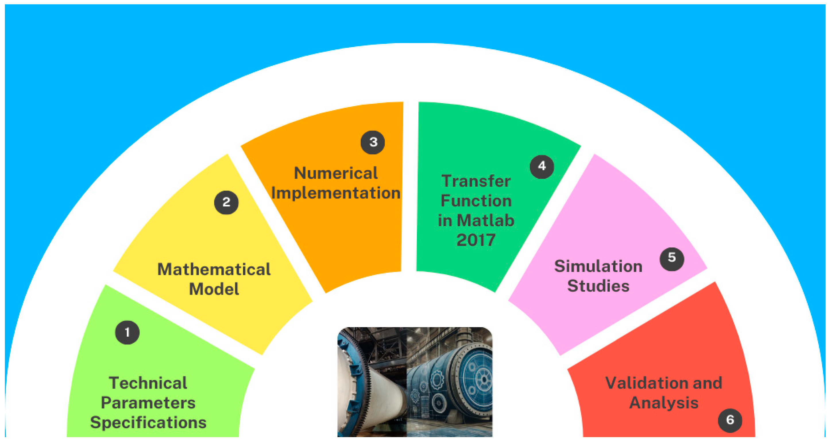
The following flow diagram (Figure 2) summarizes the key steps of our methodology, from system modelling to experimental validation.

2.2.1. Technical Parameters Specifications

The first step in our study is the comprehensive modelling of the components of the centrifugal sugar dryer system. These include the treated steam radiator (pure condensate without hardness), the bulkhead in which the exchange of hot and cold air was carried out, and the 74,570 Watts fan, which functions as an extractor of the air passing through the sugar dryer. The behaviour of hot air flow inside a centrifugal sugar dryer is studied. The dryer contains a rotor with internal blades that induce turbulent fluid motion. The physical model includes the following: three-dimensional, incompressible, and turbulent flow, convective heat transfer between the air and the internal walls of the drum, and simulation of the relative motion induced by the rotor.

2.2.2. Mathematical Model

Mathematical models are developed to precisely represent the dynamic behaviour of these components in different operating conditions. The mathematical model is based on the thermal balance inside the rotary sugar dryer, considering the air as fluidized under its real conditions. The applied mathematical Navier–Stokes equation (momentum and continuity) model is also the standard k-ε turbulence model and is suitable for industrial flows with a certain degree of anisotropy in industrial CFD, for the analysis of turbulent fluid motion.

2.2.3. Numerical Implementation

The numerical implementation of the digital twin for geometric design and tools was based on the geometry modeled in Inventor 2019 for the CAD model, with the computational domain exported in step format. The mesh generation applied through CFD2015 meshing software was the hexahedral structured mesh in the drum and tetrahedral structured zone in the rotor region, considering the quality criteria in orthogonality and asymmetry. For the simulation, a solver type (Solver) was considered at a stationary base pressure; for the discretization, the second-order equation for all variables and a residual convergence were considered. A new strategy was developed to find the ideal conditions of the centrifugal sugar dryer. This strategy integrates an approach based on the k-ε standard in industrial CFD to optimise fluidization in its temperature and air velocity variables for sugar drying. This strategy integrates an approach based on the k-ε standard in industrial CFD to optimise the fluidization in its temperature and air velocity variables for sugar drying.

2.2.4. Transfer Function in MATLAB R2017

In general, this method is determined by the heat transfer function of the fluid (air) within the system inside the centrifugal sugar dryer, where it is carried out under the analysis of the energy balance equation. This study considers that the accumulated thermal energy of the fluid inside the centrifugal sugar dryer is equal to the thermal energy of the fluid whose behaviour remains homogeneous inside the centrifugal dryer. This approach aims to optimise the robustness and performance indicator of the centrifugal sugar dryer.

2.2.5. Simulation Studies

Simulation strategies of the airflow were carried out in a digital twin environment using CFD 2015 software. Thermal performance evaluations were carried out under simulations of the system at different air velocities, considering a 74,570 Watts fan as the exhaust fan inside the centrifugal sugar dryer. These simulations help to validate the effectiveness of the strategy in achieving stable and efficient energy conversion. For the CFD simulation, the Navier–Stokes equations were solved together with the energy equation, using the standard k-ε turbulence model. The mesh was verified through a mesh independence study, and boundary conditions representative of the dryer’s real operation were applied. The numerical solution was considered converged when the residuals of the conservation equations were below 10−5 and the energy variation was less than 10−6.

2.2.6. Validation and Analysis

The simulation results have been extensively analysed for validation strategies based on the thermal behaviour of fluidisation. Critical performance metrics such as temperature and optimal thermal air speed were evaluated. In addition to the standard tests, extended simulations were carried out that covered different seasonal conditions to evaluate the thermal fluidisation performance and stability of the system. This exhaustive analysis confirmed that the strategies of the standard k-ε method in industrial CFD are robust and consistent under real operating conditions. For model validation, quantitative experimental data of the physical system were considered, allowing the simulated behaviour to be compared with real observations.

2.3. Mathematical Model of the Technologic System

The specialised unit present in the virtual environment was classified into the following two classes: those for whom the study, over time, made it possible to determine the variable value in a category, and those whose condition was adapted to a digital variable.
The supply of air to the centrifugal dryer, where the sugar is treated to remove humidity, is by forced convection from the environment, which passes through the coils of a radiator at a certain temperature. An ideal operating temperature is expected to be reached, and as the temperature value varies over time, a thermal dynamic system is created. This depends on the ability of the elements involved in the digital twin and the physical properties to reach the ideal temperature in a timely manner.
According to the above, the fluid inside the centrifugal sugar dryer must be characterized by the transfer function obtained in the energy balance. To obtain the dynamic system, the function of temperature differences was used, which considers the accumulation of thermal energy of the fluid inside the centrifugal sugar dryer, as well as the loss of energy by conduction. For energy loss due to conduction, it is considered zero since the centrifugal sugar dryer is well insulated, as shown in the following Equation (1):
V C p ρ d T d t = ρ C p F T e T t + Q T t T a ( t ) R
where V represents the volume of the centrifugal sugar dryer, Cp is the specific heat of the ambient air at 40 °C, ρ is the density of the ambient air, F is the mass flow rate of the ambient air, Te is the initial or inlet temperature of the ambient air, T(t) is the ambient air temperature at the exit of the centrifugal dryer, Q is the heat flux applied to the fluid inside the centrifugal dryer, Ta(t) is the ambient temperature outside the centrifugal dryer, and R is the thermal resistance of the material adhered to the centrifugal dryer.
According to Equation (2), where the correlation of the stimulating signal and the response signal is shown, in regard to obtaining the transfer function of the centrifugal sugar dryer with this relationship, it is demonstrated that the application theory is that of classical control. Therefore, we present the dynamic transfer function in the Laplace domain in Equation (2) in the following way:
T Q = 1 K 1 S + K 2
The corresponding equation in the Laplace domain, which represents the centrifugal sugar dryer (plant), must be obtained in discrete time so that the system can recognise the operation of the centrifugal dryer in a real-time digital twin. Therefore, in accordance with the state-of-the-art models of dynamic thermal systems and according to the above, the Tustin method or linear transformation method was applied.
In Equation (2), the application of period T = 0.05 is considered, and Z−1 represents S, which characterizes the complex domain in the bilinear transformation. Considering a period less than 0.05, the substitution in Equation (3) is shown below, where T represents the period of the digital function, and Z is the transformation in the digital domain. Thus, the fluid constants are represented by K1 and K2, and Q is the thermal constant, which are used to obtain Equation (3) in the digital domain, shown as follows:
T ( Z ) = Q ( Z ) K 1 2 T 1 Z 1 1 + Z 1 + K 2
According to the mathematical development, to virtualise the centrifugal dryer process and to establish the dynamic system model, it is possible to derive the necessary control signal in time (heat flow) to control the temperature of the composition in the centrifugal dryer. This is because the technical parameters of the centrifugal dryer operating in real time in the sugar mill have been included to obtain the discretised Equation (4) of the system. However, this system is mainly implemented using a MATLAB programming code.
T K = T Q K 1 T ρ C P F + 2 V ρ C P + T Q K T ρ C P F + 2 V ρ C P + T ρ C P F 2 V ρ C P T K 1 T ρ C P F + 2 V ρ C P

2.4. Standard k-ε Method Used in Industrial CFD

The applied research carried out in this project used the standard k-ε turbulence model, which has become the workhorse of practical engineering flow calculations due to its multiple advantages. The standard k-ε model is robust and stable, making it suitable for a wide range of turbulent flow applications. It is also computationally efficient, allowing for accurate simulations to be carried out without consuming many resources. This model is less sensitive to boundary conditions and provides reasonable accuracy for many types of flows, particularly those where the turbulence is isotropic. The standard k-ε method relies on fluid export equations to forecast and simulate turbulent kinetic energy (k) and fluid energy loss (ε), as shown in Equations (5) and (6), respectively. This model assumes that the flow is turbulent and that other effects, such as molecular viscosity, are negligible. It is therefore only valid for turbulent flows.
ρ u ¯ k x + ρ v ¯ k y = x μ + μ 1 σ k k x + y μ + μ t σ k k y + P k + G k ρ ε Y M
ρ u ¯ ε x + ρ v ¯ ε y = x μ + μ 1 σ ε ε x + y μ + μ t σ ε ε y + C 1 ε ε K P K + C 3 ε G K C 2 ε ρ ε 2 K

2.5. Turbulence Model Selection

In this industrial application, the standard k-ε turbulence model was initially chosen due to its computational robustness, simplicity, and extensive validation in industrial flows. This model solves the following two equations: one for turbulent kinetic energy (k) and another for its dissipation rate (ε), which allows for estimating the average effects of turbulence on the flow. Although it presents limitations in areas with strong pressure gradients, flow separation, or intense recirculation, its performance is acceptable in configurations with predominantly developed flow and less complex geometries. In the context of hot air fluidization, the standard k-ε model provides a first approximation of the temperature and velocity fields with relatively low computation times. However, it is recognised that more advanced models, such as k-ε realisable or k-ω SST, could offer greater accuracy in regions close to walls or in the presence of complex rotational flows; thus, their application could be considered in future stages of this study.

3. Results

The results obtained from the digital twin research show that the experiments are consistent with the discrete time response to the manipulation of the centrifugal sugar dryer. Firstly, the transfer function was determined experimentally for the mathematical analysis to demonstrate that the digital twin is possible to operate. A simulation was carried out in MATLAB R2015 in real time in order to define the operation of the digital twin under continuous real-time response conditions. Obtaining the plant’s transfer function was a priority, and the bilinear was used to obtain the equation in terms of discrete time. Experimental tests were subsequently verified in the centrifugal sugar dryer based on the digital twin to analyse the behaviour of air as a thermal fluid, which is the fluid used to dry sugar in the sugar mill. The following two experimental tests were executed by the CFD 2015 software: the first experiment was carried out under the current operating conditions of the rotary dryer to find the causes of the current problem, and the second experiment was carried out to find the ideal conditions under which the rotary dryer should operate to solve the problem.

3.1. Experimental Determination of the Transfer Function in Matlab R2015

Section 2.2 shows the mathematical equations of the system or plant that were developed To analyse the behaviour of the plant and to obtain the response as a function of continuous time, the definition of the energy balance equation was used to achieve the transfer function under the Laplace transform technique and the MATLAB R2015 software (Figure 2). To meet the stated objective of the operation of the digital twin, the transfer function obtained under the Laplace method was discretized under the bilinear method of the Z transform to obtain the discrete-time response in the MATLAB R2015 software, which also means o characterise the discrete-time dynamic model from the factory rotary dryer to be realised, with the purpose of discretizing the dynamic behaviour of the procedure in the virtual environment on the embedded physical electronic card of the digital twin established as a rotary sugar dryer.
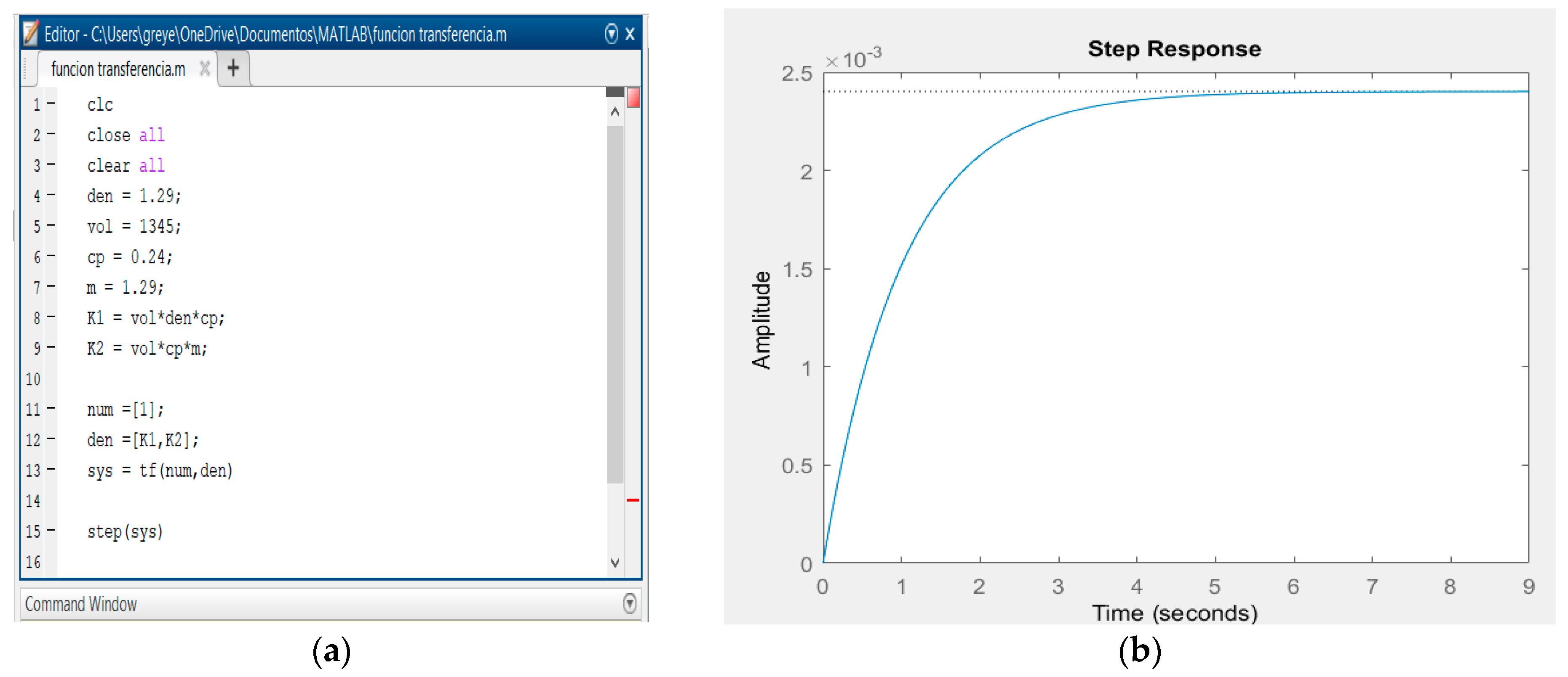
As shown in Figure 3, we obtained the discrete-time response, in which the programming code in MATLAB R2015, which is related to the application of the Tustin method, is presented. The programming considers the density of the ambient air, mass flow, specific heat, and the volume of the centrifugal sugar dryer, and it also presents the behaviour of the discretized function of the plant acting as the digital twin with a sampling period of 0.05.
According to the behaviour of the plant in continuous time (Figure 3) and the behaviour of the plant in discrete time (Figure 4), the dynamic response of the system is about five seconds in both cases. However, the stationary part in continuous time is observed up to four seconds, and the discrete part is only observed up to two seconds. Thus, according to the dates obtained, the digital twin was adapted to the real conditions and observed a high response to thermal behaviour.

3.2. Experimental Analysis of Centrifuge Dryer in CFD2015

As shown in Section 2.3, it is suggested to apply the standard k-ε turbulence model to experiments with the CFD2015 software, as well as the mathematical equations directly applied by the software to analyse the behaviour of the fluid inside the rotary dryer, both in its actual condition and in the ideal condition under which the rotary sugar dryer should operate. For the CFD simulation of the centrifugal sugar dryer using hot air injection and the standard k-ε turbulence model, a hybrid mesh was employed that combined structured and unstructured regions. This approach balances numerical accuracy in regular flow zones with the flexibility required to discretize complex geometries, such as the rotor and internal blades. A structured hexahedral mesh was used in cylindrical regions, such as the air inlet and outer casing, improving the alignment with flow direction and aiding convergence. A tetrahedral unstructured mesh was applied in the internal region, especially around the rotating blades and rotor, where geometric complexity and flow recirculation required local refinement. Inflation layers were added near solid surfaces (walls and blades) to capture thermal and velocity boundary layers, although wall refinement was moderate since the k-ε standard model uses wall functions and does not require low y+ values. Since the standard k-ε model was selected, it was not necessary to use a highly refined near-wall mesh, as this model is compatible with y+ values in the range of 30–300 by employing wall functions. Figure 5 shows the design of the rotary sugar dryer used to carry out the experiments.
In this study, two types of experimental analyses were carried out. The first was an experiment carried out in the operating conditions of the rotary sugar dryer in order to observe which variables are outside the ideal operating ranges, and the second was used to predict the ideal conditions in which the control system of the rotary sugar dryer should operate.

3.2.1. Testing in Actual Conditions

Currently, the rotary sugar dryer at the Benito Juárez sugar mill, located in the city of Cárdenas, Tabasco, operates through a thermal process induced by a heat exchanger (radiator). A partition in the middle part of the dryer separates the hot air from the cold air. In the cold air section, there is a central duct that communicates with the centrifugal fan, through which the ambient air is sucked. This sucked air passes through the heat exchanger and is the object of analysis in the fluidisation system, to observe the behaviour of the variables to be controlled. To define how to carry out this analysis, the boundary conditions of the elements mentioned in the digital twin had to be defined. Once this was done, the mesh was configured in the software. In this numerical grid, you can see the relevant numerical representations of the interactions to be integrated into the geometric figure. As shown in Figure 6, the network has 1,092,002 nodes and 4,160,140 elements for the simulation.
The corresponding simulation interactions provided the graph (Figure 5b) of the dynamic system setup and behaviour of the variables, as well as the airflow and temperature distribution through the drying system. The results shown in the graph (Figure 5b) were the product of 300 interactions detailing the behaviour of each of the variables involved. The airflow, represented by the blue line on the ‘X’ axis, remains unstable. The temperature, represented by the green line, appears stable but is high, which is the first cause of poor operation.
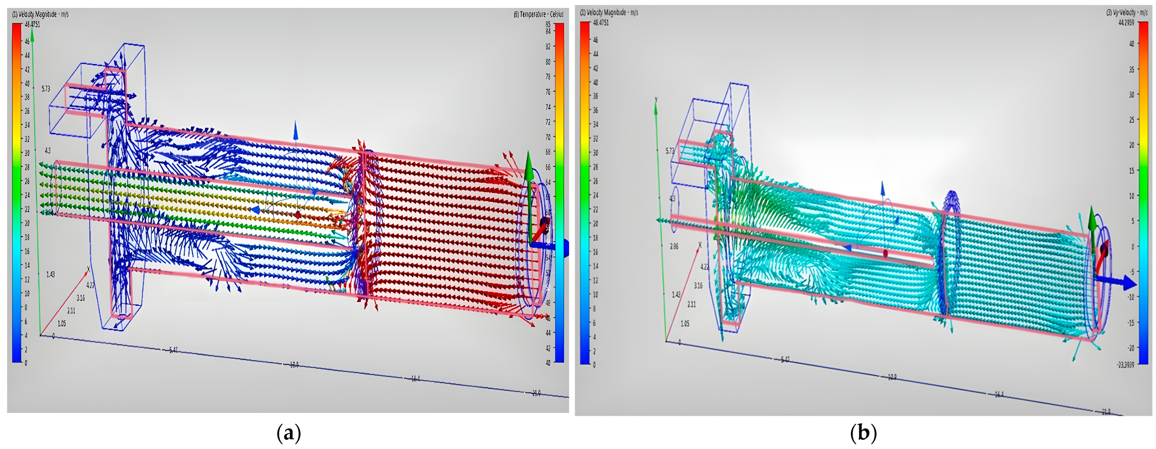
In Figure 7, a maximum temperature of 205.17 °C was observed at a point in the dryer, which is problematic since, at this temperature, the sugar melts and becomes compacted, disrupting the operation of the equipment. Furthermore, it was assumed or modeled as such through the numerical approach employed in the center of the equipment, where the partition that separates the hot and cold air mixture is located. Sugar material was observed to be entrained at the dryer outlet, due to the flow velocity reaching 54 m/s. This caused poor drying and compaction due to caramelization and sugar reflux into the dryer. Finally, it was observed that the cold air flow from the environment was not adequately supplying the dryer; quite the opposite, it was leaving the dryer mixed with hot air and with sugar dust loss to the atmosphere.

3.2.2. Experimentation for the Prediction of Ideal Conditions

Due to the internal analysis of equipment operation, adjustments were applied to the equipment using the same procedure for predicting ideal conditions.
According to the analysis carried out, the problems of the variables were identified. The air velocity in the fan and the temperature in the radiator were modified. The results obtained after assigning the boundary conditions to the elements in the digital twin are shown in Figure 8.
In the CFD software, the mesh was established for the calculation of the interactions to be integrated in the geometrical figure. The mesh has 1,175,386 nodes and 4,775,685 elements for the simulation. As shown in the graph of Figure 7b, the dynamic system shows a stable behaviour, with the temperature constant at 97 °C and a velocity of 48 m/s on the X-axis. The pressure shows small fluctuations that are considered negligible.
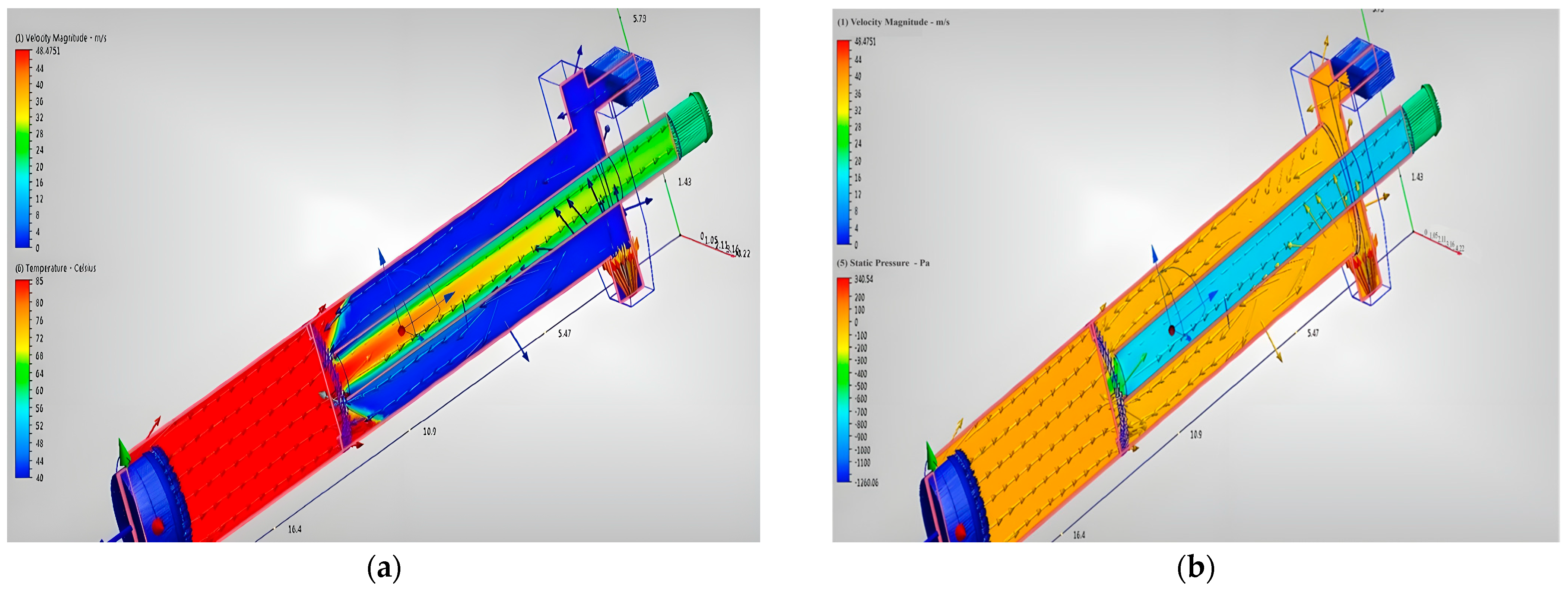
Figure 9 shows the fluidisation simulation of the interacting variables in the operation of the rotary dryer. Figure 8a (left) shows the thermal distribution of the fluidised and vectorial behaviour in the different compartments of the rotary dryer, resulting in a turbulent flow in the hot and cold air mixing zone. The uniform temperature of 85 °C is presented on the right side of Figure 8b, where the humidity is extracted from the sugar and the air flow is extracted by the fan, and it behaves in a laminar form. In this proposal, the ambient air maintains the sugar temperature between 30 and 35 °C, which is ideal for continuing the packaging process without compressing and melting the raw material.
Figure 9b on the right shows the behaviour of the velocities in the X-axis of the fluidised system. The simulation shows that the airflow reaches a maximum speed of 48 m/s in a uniform form, with minor turbulence in the centre of the equipment or in the bulkhead towards the sugar outlet due to the thermal treatment of the airflows circulating through the centrifugal dryer. However, these peak speeds have no influence on the operation of the dryer.
Figure 10 shows the correct form in which the centrifugal dryer should operate for sugar drying according to the prediction of the ideal variables. Figure 10a clearly shows the thermal behaviour that the sugar should receive to remove moisture from both the hot and cold fluidised sugar throughout the centrifugal dryer. In addition, Figure 10b shows the behaviour of the fluidised pressure. The simulation shows that the pressure remains stable in all parts of the dryer, without alterations or overpressure. According to the results, the centrifugal sugar dryer remained at 205.17 °C with a turbulent fluidised particle velocity of 54 m/s for the first experiment and at 97 °C with a fluidised particle velocity of 48 m/s in the second experiment. This was conducted in order to analyse the recognised thermodynamic tables on the principle of using a pure condensate without hardness inside the system. It was found that, at 205.17 °C, the internal energy of the steam (enthalpy) was 2600.1 Kj/kg, and at 85 °C, the internal energy of the vapour (enthalpy) was 2489.6 Kj/kg. According to the experiments in which the ideal predictable variables were presented, for the centrifugal dryer to work correctly, the second experiment was considered. Therefore, it was observed that there was a temperature difference and, therefore, a decrease in the internal energy of the steam, resulting in a steam energy saving of 4.25%.

3.3. Experimental Data and CFD Model Validation

This section considers a centrifugal sugar dryer operating in a sugar mill in Villahermosa. As mentioned, this equipment is obsolete due to the conditions in which it operates and the lack of recommended variables to monitor and control it under ideal conditions. For the reasons mentioned above, in this centrifugal sugar dryer, the only experimental data under real conditions that are monitored are the hot air temperature at the dryer inlet and the air temperature at the outlet. Forced air is applied by a 74,570-Watt fan under uncontrolled conditions to supply constant air speed. Hence, the use of emerging technologies, such as digital twins, is recommended to improve and update these industrial systems to their ideal conditions under the validation of CFD models.

3.3.1. Experimental Data Under Real Conditions

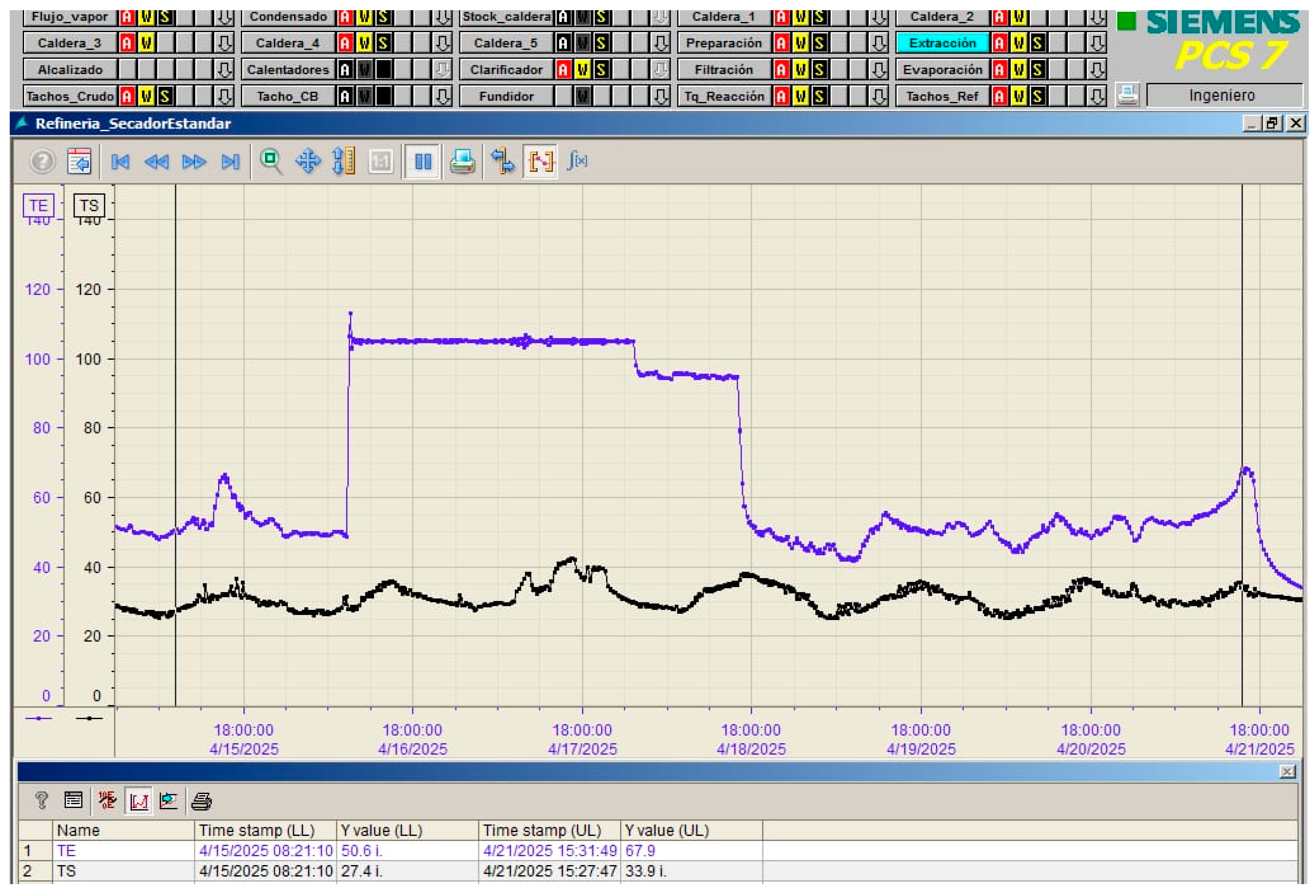
To validate the developed CFD model, real-time experimental data obtained from the Siemens PCS 7 distributed control system (DCS), corresponding to a centrifugal sugar dryer operating with hot air, were used. The variables considered were the inlet air temperature (TE) and the outlet temperature (TS) during continuous operation between 15 and 21 April 2025, as shown in Figure 11.
Measurements show dynamic thermal behaviour that responds to the operating conditions of the dryer. The inlet air temperature (TE) ranged between 50 and 105 °C, while the outlet temperature (TS) ranged between 27 and 44 °C. For the temperature conditions required by the centrifugal sugar dryer for proper operation, the conditions shown in Table 2 were considered.

3.3.2. Validación del Modelo CFD

The results obtained using computational fluid dynamics (CFD) were compared with experimental data under real conditions to evaluate the accuracy of the model under ideal conditions. The validation was carried out by comparing the simulated values with those recorded by the plant’s pt100 sensors (thermo resistive device). This device contains a platinum wire that, at 0 °C, has 100 ohms, and as the temperature increases, its electrical resistance increases. The validation is shown in Table 3.
The results of the CFD model were compared with experimental data from the drying system under real conditions. The comparison of the air inlet temperatures (TE) and the outlet temperature (TS) shows acceptable agreement, with relative errors less than 5%, which validates the reliability of the numerical model to predict the thermal behaviour of the system.

4. Discussion

In this study, the behaviour of the centrifugal sugar dryer was evaluated with the DT methodology using CFD simulations and the standard k-ε turbulence model. The results obtained show the stable behaviour of the dynamic system at a temperature of 85 °C and an air flow velocity of 48 m s−1. The temperature of 85 °C is crucial to avoid the melting and compaction of the sugar, in agreement with the results obtained by Polasak Srinavin [37] and Palacios-Bereche [38], where they pointed out the importance of maintaining a controlled temperature to ensure the quality of the final product. The air velocity achieved was a maximum of 48 m/s in a uniform manner, ensuring uniform heat distribution and efficient moisture removal without affecting the quality of the sugar. In terms of energy efficiency, a study by Mkwananzi [39] found that, by reducing the peak velocity and improving air flow distribution, the overall efficiency of the system could be increased by 2 to 4% [39]. These results, when compared to the scientific literature, are favourable for the Cardenas Tabasco sugar factory.
In summary, these results support the assertion that the CFD model is robust and provides an effective tool for the accurate design and simulation of performance in various areas at the industrial level, such as aerospace, automotive, energy, chemical processes, and the environment. This shows that the k-ε model is effective when applied to different industrial areas, as shown in Table 4, under different operating conditions. Despite its challenges and limitations in the different industrial areas shown in Table 4, it was not necessary to apply complex adverse conditions in the application of the centrifugal sugar dryer. Additionally, there was no difficulty in capturing interactions and no limitations in prediction with high anisotropy or mass transfer phenomena. This demonstrates that the application of the centrifugal sugar dryer under the DT methodology, applying the CFD model k-ε standard r, gave us the solution to the problem identified in the sugar mill of Cardenas, Tabasco.

5. Conclusions

In this research, digital twin technology was used to build an integral model of a piece of industrial equipment (centrifugal dryer) with the aim of identifying the deficiencies in the sugar drying process in a sugar mill in Cardenas Tabasco, Mexico. This allowed us to solve the problems related to sugar densification in real time and to diagnose the variables that cause failures, thus avoiding plant downtime. By assigning boundary conditions of external factors (e.g., ambient air parameters, radiator parameters, centrifugal fan parameters, and centrifugal dryer parameters), a fluid system was created to diagnose actual variables and predict ideal variables in the digital twin.
Design software such as Autodesk Inventor 2017, CFD2015 industrial, and MATLAB R2017 helped overcome the limitations of idealised factors in modelling. The digital twin technology avoided the need to stop the operation of the plant for experimentation, as in the traditional system, resulting in a more complete description of the operating status and working conditions. The digital twin model was experimented with the actual operating conditions of the centrifugal dryer, identifying out-of-range variables and diagnosing operational problems in real time. Its viability and accuracy in fault diagnosis were subsequently verified experimentally to predict the ideal variables under which the centrifugal dryer should operate. Finally, the digital twin model fulfilled our initial expectations of high accuracy, 3D visualisation, and interaction.
The application of the digital twin allowed for the detection of variables outside the parameters that cause the centrifugal sugar dryer to malfunction. Therefore, the adaptability of the digital twin for plant diagnosis through specific simulations applicable under the real parameters of the centrifugal sugar dryer was proposed. Similarly, the experimental results showed that the proposed method guarantees that, by using the digital twin models, the ideal variables for the correct operation of the centrifugal sugar dryer can be predicted without stopping the factory, thus avoiding economic losses. Additionally, by controlling the ideal temperature variable, the system improved its efficiency and, therefore, saved energy by 4.25%.

Author Contributions

Conceptualization, V.G.-H., V.A.B.L., and B.E.G.S.; methodology, G.R.-M.; software, J.O.-M.; validation, L.C.S.H., G.R.-M., and J.O.-M.; formal analysis, G.A.R.; investigation, Q.R.Q.B.; resources, C.C.-D.; data curation, G.A.R.; writing—original draft preparation, G.R.-M.; writing—review and editing, L.C.S.H.; visualization, V.G.-H.; supervision, B.E.G.S. and V.A.B.L.; project administration, Q.R.Q.B. All authors have read and agreed to the published version of the manuscript.

Funding

This research received no external funding.

Data Availability Statement

The data that support the findings of this study are available from the corresponding author upon reasonable request.

Conflicts of Interest

The authors declare no conflicts of interest.

References

  1. Singh, M.; Srivastava, R.; Fuenmayor, E.; Kuts, V.; Qiao, Y.; Murray, N.; Devine, D. Applications of Digital Twin across Industries: A Review. Appl. Sci. 2022, 12, 5727. [Google Scholar] [CrossRef]
  2. Segovia, M.; Garcia-Alfaro, J. Design, Modeling and Implementation of Digital Twins. Sensors 2022, 22, 5396. [Google Scholar] [CrossRef] [PubMed]
  3. Menon, D.; Anand, B.; Chowdhary, C.L. Digital Twin: Exploring the Intersection of Virtual and Physical Worlds. IEEE Access 2023, 11, 75152–75172. [Google Scholar] [CrossRef]
  4. Bamunuarachchi, D.; Georgakopoulos, D.; Banerjee, A.; Jayaraman, P.P. Digital Twins Supporting Efficient Digital Industrial Transformation. Sensors 2021, 21, 6829. [Google Scholar] [CrossRef]
  5. Deng, M.; Menassa, C.C.; Kamat, V.R. From BIM to Digital Twins: A Systematic Review of the Evolution of Intelligent Building Representations in the AEC-FM Industry. J. Inf. Technol. Constr. 2021, 26, 58–83. [Google Scholar] [CrossRef]
  6. Leng, J.; Wang, D.; Shen, W.; Li, X.; Liu, Q.; Chen, X. Digital Twins-Based Smart Manufacturing System Design in Industry 4.0: A Review. J. Manuf. Syst. 2021, 60, 119–137. [Google Scholar] [CrossRef]
  7. Wu, J.; Zuo, R. Intelligent Computation Offloading Based on Digital Twin-Enabled 6G Industrial IoT. Appl. Sci. 2024, 14, 1035. [Google Scholar] [CrossRef]
  8. Guerrero-Hernandez, V.; Reyes-Morales, G.; Jacome-Onofre, P.; Ortega Moody, J.A.; Matacapan-Toto, F.A.; Martínez Herrera, M.A. Integration of an Industrial Control to a Digital Twin at the Industrial Level. In Proceedings of the 2023 3rd International Conference on Electrical, Computer, Communications and Mechatronics Engineering (ICECCME), Tenerife, Spain, 19–21 July 2023; IEEE: Piscataway, NJ, USA, 2023; pp. 1–8. [Google Scholar]
  9. Lopes, P.V.; Silveira, L.; Guimaraes Aquino, R.D.; Ribeiro, C.H.; Skoogh, A.; Verri, F.A.N. Synthetic Data Generation for Digital Twins: Enabling Production Systems Analysis in the Absence of Data. Int. J. Comput. Integr. Manuf. 2024, 37, 1252–1269. [Google Scholar] [CrossRef]
  10. González-Herbón, R.; González-Mateos, G.; Rodríguez-Ossorio, J.R.; Domínguez, M.; Alonso, S.; Fuertes, J.J. An Approach to Develop Digital Twins in Industry. Sensors 2024, 24, 998. [Google Scholar] [CrossRef]
  11. Hu, Y.; Taha, O.W.; Yang, K. Fault Detection in Active Magnetic Bearings Using Digital Twin Technology. Appl. Sci. 2024, 14, 1384. [Google Scholar] [CrossRef]
  12. Molinaro, R.; Singh, J.-S.; Catsoulis, S.; Narayanan, C.; Lakehal, D. Embedding Data Analytics and CFD into the Digital Twin Concept. Comput. Fluids 2021, 214, 104759. [Google Scholar] [CrossRef]
  13. Dixon, A.G.; Partopour, B. Computational Fluid Dynamics for Fixed Bed Reactor Design. Annu. Rev. Chem. Biomol. Eng. 2020, 11, 109–130. [Google Scholar] [CrossRef] [PubMed]
  14. Haringa, C. An Analysis of Organism Lifelines in an Industrial Bioreactor Using Lattice-Boltzmann CFD. Eng. Life Sci. 2023, 23, e2100159. [Google Scholar] [CrossRef]
  15. Wang, C.-N.; Yang, F.-C.; Nguyen, V.T.T.; Vo, N.T.M. CFD Analysis and Optimum Design for a Centrifugal Pump Using an Effectively Artificial Intelligent Algorithm. Micromachines 2022, 13, 1208. [Google Scholar] [CrossRef]
  16. Wutz, J.; Waterkotte, B.; Heitmann, K.; Wucherpfennig, T. Computational Fluid Dynamics (CFD) as a Tool for Industrial UF/DF Tank Optimization. Biochem. Eng. J. 2020, 160, 107617. [Google Scholar] [CrossRef]
  17. Nidhul, K.; Yadav, A.K.; Anish, S.; Arunachala, U.C. Efficient Design of an Artificially Roughened Solar Air Heater with Semi-Cylindrical Side Walls: CFD and Exergy Analysis. Sol. Energy 2020, 207, 289–304. [Google Scholar] [CrossRef]
  18. Jaszczur, M.; Młynarczykowska, A.; Demurtas, L. Effect of Impeller Design on Power Characteristics and Newtonian Fluids Mixing Efficiency in a Mechanically Agitated Vessel at Low Reynolds Numbers. Energies 2020, 13, 640. [Google Scholar] [CrossRef]
  19. Yamini, O.A.; Movahedi, A.; Mousavi, S.H.; Kavianpour, M.R.; Kyriakopoulos, G.L. Hydraulic Performance of Seawater Intake System Using CFD Modeling. J. Mar. Sci. Eng. 2022, 10, 988. [Google Scholar] [CrossRef]
  20. Zhang, C.; Bounds, C.P.; Foster, L.; Uddin, M. Turbulence Modeling Effects on the CFD Predictions of Flow over a Detailed Full-Scale Sedan Vehicle. Fluids 2019, 4, 148. [Google Scholar] [CrossRef]
  21. Mani, M.; Dorgan, A.J. A Perspective on the State of Aerospace Computational Fluid Dynamics Technology. Annu. Rev. Fluid Mech. 2023, 55, 431–457. [Google Scholar] [CrossRef]
  22. Zhao, Y.; Akolekar, H.D.; Weatheritt, J.; Michelassi, V.; Sandberg, R.D. RANS Turbulence Model Development Using CFD-Driven Machine Learning. J. Comput. Phys. 2020, 411, 109413. [Google Scholar] [CrossRef]
  23. Didane, D.H.; Bajuri, M.N.A.; Manshoor, B.; Boukhari, M.I. Performance Investigation of Vertical Axis Wind Turbine with Savonius Rotor Using Computational Fluid Dynamics (CFD). CFD Lett. 2022, 14, 116–124. [Google Scholar] [CrossRef]
  24. Park, D.; Go, J.S. Design of Cyclone Separator Critical Diameter Model Based on Machine Learning and CFD. Processes 2020, 8, 1521. [Google Scholar] [CrossRef]
  25. Nakhaei, M.; Lu, B.; Tian, Y.; Wang, W.; Dam-Johansen, K.; Wu, H. CFD Modeling of Gas–Solid Cyclone Separators at Ambient and Elevated Temperatures. Processes 2020, 8, 228. [Google Scholar] [CrossRef]
  26. Ngo, S.I.; Lim, Y.-I. Multiscale Eulerian CFD of Chemical Processes: A Review. ChemEngineering 2020, 4, 23. [Google Scholar] [CrossRef]
  27. Acharya, T.; Casimiro, L. Evaluation of Flow Characteristics in an Onshore Horizontal Separator Using Computational Fluid Dynamics. J. Ocean Eng. Sci. 2020, 5, 261–268. [Google Scholar] [CrossRef]
  28. Kuang, S.; Zhou, M.; Yu, A. CFD-DEM Modelling and Simulation of Pneumatic Conveying: A Review. Powder Technol. 2020, 365, 186–207. [Google Scholar] [CrossRef]
  29. Yi, H.; Kim, M.; Lee, D.; Park, J. Applications of Computational Fluid Dynamics for Mine Ventilation in Mineral Development. Energies 2022, 15, 8405. [Google Scholar] [CrossRef]
  30. Pramadhony; Kaprawi, S.; Dewi, P.; Muhammad, S.; Sugianto. The Effects of the Exhaust Fan Position to Indoor Air Pollution Distribution in Enclosed Parking Garage. CFD Lett. 2023, 15, 123–138. [Google Scholar] [CrossRef]
  31. Kim, R.; Hong, S.; Norton, T.; Amon, T.; Youssef, A.; Berckmans, D.; Lee, I. Computational Fluid Dynamics for Non-Experts: Development of a User-Friendly CFD Simulator (HNVR-SYS) for Natural Ventilation Design Applications. Biosyst. Eng. 2020, 193, 232–246. [Google Scholar] [CrossRef]
  32. Martins, J.R.R.A. Aerodynamic Design Optimization: Challenges and Perspectives. Comput. Fluids 2022, 239, 105391. [Google Scholar] [CrossRef]
  33. Atmaca, M.; Ezgi, C. Three-Dimensional CFD Modeling of a Steam Ejector. Energy Sources Part A Recovery Util. Environ. Eff. 2022, 44, 2236–2247. [Google Scholar] [CrossRef]
  34. Tutar, M.; Üstün, C.E.; Campillo-Robles, J.M.; Fuente, R.; Cibrián, S.; Arzua, I.; Fernández, A.; López, G.A. Optimized CFD Modelling and Validation of Radiation Section of an Industrial Top-Fired Steam Methane Reforming Furnace. Comput. Chem. Eng. 2021, 155, 107504. [Google Scholar] [CrossRef]
  35. Langrish, T.A.G.; Harrington, J.; Huang, X.; Zhong, C. Using CFD Simulations to Guide the Development of a New Spray Dryer Design. Processes 2020, 8, 932. [Google Scholar] [CrossRef]
  36. Bhatti, M.M.; Marin, M.; Zeeshan, A.; Abdelsalam, S.I. Editorial: Recent Trends in Computational Fluid Dynamics. Front. Phys. 2020, 8, 593111. [Google Scholar] [CrossRef]
  37. Srinavin, P.; Laloon, K.; Wongwuttasatien, T.; Patra, S.; Padungthon, S. Drying process optimization and kinetic study of sugarcane filter cake using a pilot-scale rotary dryer. Res. Sq. 2023. [Google Scholar] [CrossRef]
  38. Palacios-Bereche, M.C.; Palacios-Bereche, R.; Ensinas, A.V.; Gallego, A.G.; Modesto, M.; Nebra, S.A. Brazilian sugar cane industry–A survey on future improvements in the process energy management. Energy 2022, 259, 124903. [Google Scholar] [CrossRef]
  39. Mkwananzi, T.; Mandegari, M.; Görgens, J.F. Disturbance Modelling through Steady-State Value Deviations: The Determination of Suitable Energy Indicators and Parameters for Energy Consumption Monitoring in a Typical Sugar Mill. Energy 2019, 176, 211–223. [Google Scholar] [CrossRef]
  40. Huang, S.; Chen, Q.; Cheng, Y.; Xian, J.; Tai, Z. Supersonic Combustion Modeling and Simulation on General Platforms. Aerospace 2022, 9, 366. [Google Scholar] [CrossRef]
  41. Sankalp, S.S.; Sharma, V.; Singh, A.; Salian, A.S.; Srinivas, G. Computational Analyses of Tail Fin Configurations for a Sounding Rocket. Aerosp. Syst. 2022, 5, 233–246. [Google Scholar] [CrossRef]
  42. Kulshreshtha, A.; Gupta, S.K.; Singhal, P. FEM/CFD Analysis of Wings at Different Angle of Attack. Mater. Today Proc. 2020, 26, 1638–1643. [Google Scholar] [CrossRef]
  43. Rajanna, M.R.; Johnson, E.L.; Codoni, D.; Korobenko, A.; Bazilevs, Y.; Liu, N.; Lua, J.; Phan, N.; Hsu, M.C. Finite Element Methodology for Modeling Aircraft Aerodynamics: Development, Simulation, and Validation. Comput. Mech. 2022, 70, 549–563. [Google Scholar] [CrossRef]
  44. Kamal, M.N.F.; Ishak, I.A.; Darlis, N.; Maruai, N.M.; Jamian, R.; Rashid, R.A.; Samiran, N.; Hassan, N.N.M. Flow Structure Characteristics of the Simplified Compact Car Exposed to Crosswind Effects Using CFD. J. Adv. Res. Appl. Sci. Eng. Technol. 2022, 28, 56–66. [Google Scholar] [CrossRef]
  45. Ren, J.; Zhao, H.; Wang, M.; Miao, C.; Wu, Y.; Li, Q. Design and Investigation of a Dynamic Auto-Adjusting Ejector for the MED-TVC Desalination System Driven by Solar Energy. Entropy 2022, 24, 1815. [Google Scholar] [CrossRef]
  46. Shen, Y.; Zheng, T.; Lv, H.; Zhou, W.; Zhang, C. Numerical Simulation of Hydrogen Leakage from Fuel Cell Vehicle in an Outdoor Parking Garage. World Electr. Veh. J. 2021, 12, 118. [Google Scholar] [CrossRef]
  47. Tan, L.; Yuan, Y. Computational Fluid Dynamics Simulation and Performance Optimization of an Electrical Vehicle Air-Conditioning System. Alex. Eng. J. 2022, 61, 315–328. [Google Scholar] [CrossRef]
  48. Fertahi, S.D.; Belhadad, T.; Kanna, A.; Samaouali, A.; Kadiri, I. CFD Investigation of Fin Design Influence on Phase Change Material Melting for Solar Thermal Energy Storage. e-Prime—Adv. Electr. Eng. Electron. Energy 2023, 6, 100306. [Google Scholar] [CrossRef]
  49. Ngadi, Z.; Lahlaouti, M.L. CFD Modeling of Petcoke Co-Combustion in a Real Cement Kiln: The Effect of the Turbulence-Chemistry Interaction Model Applied with K-ϵ Variations. Int. Rev. Appl. Sci. Eng. 2022, 13, 148–163. [Google Scholar] [CrossRef]
  50. Saini, A.K.; Radu, T.; Paritosh, K.; Kumar, V.; Pareek, N.; Tripathi, D.; Vivekanand, V. Bioengineered Bioreactors: A Review on Enhancing Biomethane and Biohydrogen Production by CFD Modeling. Bioengineered 2021, 12, 6418–6433. [Google Scholar] [CrossRef]
  51. Antara, I.G.F.B.; Sucipta, M.; Astawa, K.; Wirawan, I.K.G.; Sukrawa, M. CFD Simulation of Photovoltaic Thermal PV/T) Cooling System with Various Channel Geometries. J. Heat Mass Transf. Res. 2024, 11, 297–306. [Google Scholar] [CrossRef]
  52. Villalobos-Lara, A.D.; Castillo, B.; Rivera, F.F.; Vazquez-Arenas, J. Model Accounting for the Cr(III) Electroprecipitation Kinetics in an Electrochemical Reactor Based on CFD and Mass Transport Contributions. J. Electroanal. Chem. 2023, 928, 117057. [Google Scholar] [CrossRef]
  53. Savarese, M.; Cuoci, A.; De Paepe, W.; Parente, A. Machine Learning Clustering Algorithms for the Automatic Generation of Chemical Reactor Networks from CFD Simulations. Fuel 2023, 343, 127945. [Google Scholar] [CrossRef]
  54. Rezaeimanesh, M.; Asghar Ghoreyshi, A.; Peyghambarzadeh, S.M.; Hassan Hashemabadi, S. A Coupled CFD Simulation Approach for Investigating the Pyrolysis Process in Industrial Naphtha Thermal Cracking Furnaces. Chin. J. Chem. Eng. 2022, 44, 528–542. [Google Scholar] [CrossRef]
  55. Jamil, Q.; Rana, K.B.; Matoh, L. A CFD Study on Optimization of Mass Transfer and Light Distribution in a Photocatalytic Reactor with Immobilized Photocatalyst on Spheres. Water 2024, 16, 1828. [Google Scholar] [CrossRef]
  56. Zohdi, T.I. A Digital Twin Framework for Machine Learning Optimization of Aerial Fire Fighting and Pilot Safety. Comput. Methods Appl. Mech. Eng. 2021, 373, 113446. [Google Scholar] [CrossRef]
  57. Fuhrman, D.R.; Li, Y. Instability of the Realizable k—ε Turbulence Model beneath Surface Waves. Phys. Fluids 2020, 32, 115108. [Google Scholar] [CrossRef]
  58. Ioannidis, G.; Li, C.; Tremper, P.; Riedel, T.; Ntziachristos, L. Application of CFD Modelling for Pollutant Dispersion at an Urban Traffic Hotspot. Atmosphere 2024, 15, 113. [Google Scholar] [CrossRef]
  59. Lin, C.; Wang, Y.; Ooka, R.; Flageul, C.; Kim, Y.; Kikumoto, H.; Wang, Z.; Sartelet, K. Modeling of Street-Scale Pollutant Dispersion by Coupled Simulation of Chemical Reaction, Aerosol Dynamics, and CFD. Atmos. Chem. Phys. 2023, 23, 1421–1436. [Google Scholar] [CrossRef]
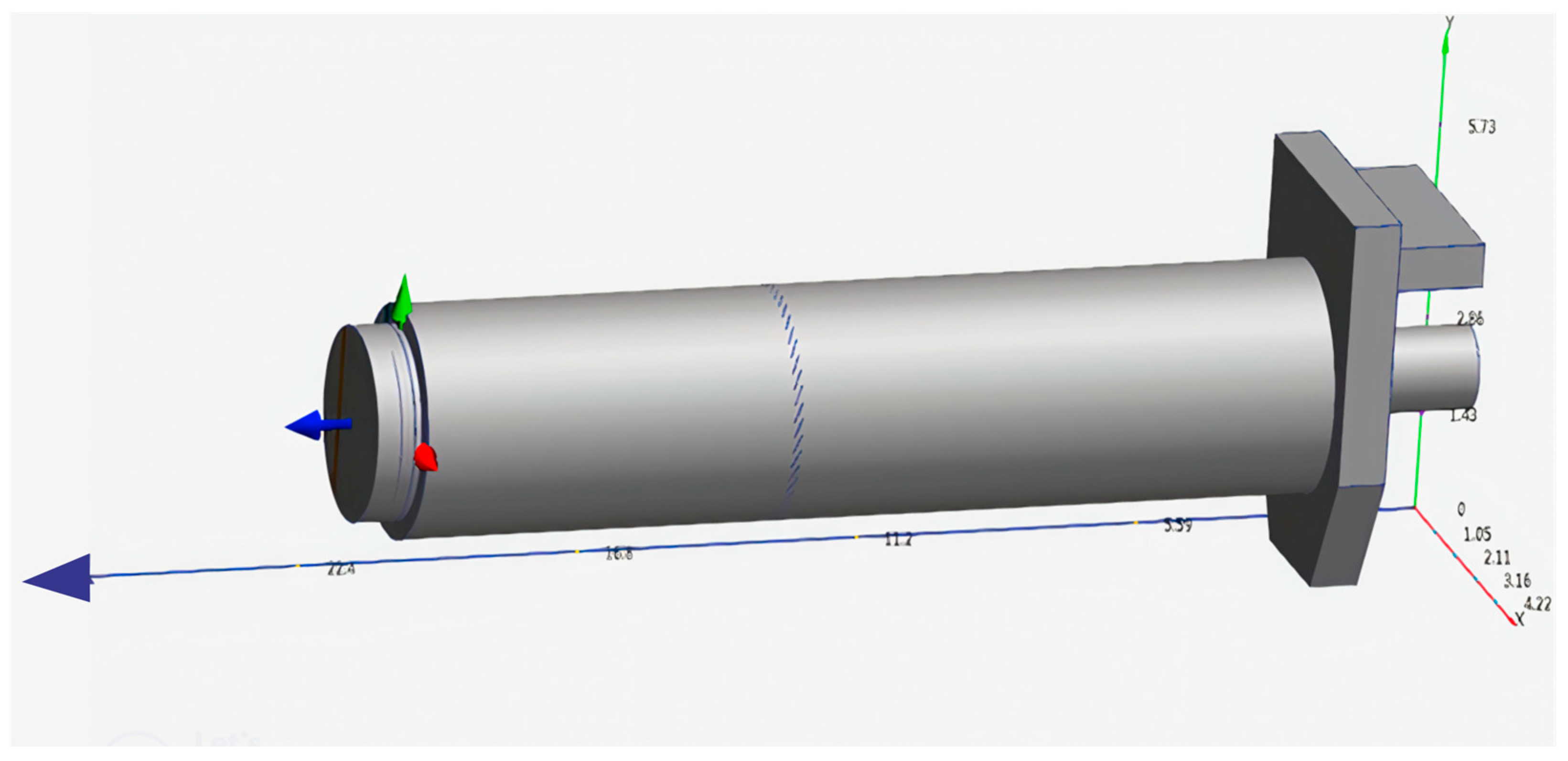
Figure 1. Dryer assembled with parametric measurements.
Fluids 10 00146 g001
Figure 2. The key steps of methodology: from system modelling to experimental validation.
Fluids 10 00146 g002
Figure 3. Continuous time response: (a) programming code in MATLAB R2015; (b) the thermal behaviour of the plant in its real scheme.
Fluids 10 00146 g003
Figure 4. Discrete time response: (a) programming code in MATLAB R2015 applying Tustin; (b) thermal behaviour of the plant in digital twin scheme.
Fluids 10 00146 g004
Figure 5. Rotary sugar dryer: (a) fully assembled in software CFD2015; (b) assignment of boundary conditions.
Fluids 10 00146 g005
Figure 6. Testing in the real conditions of the rotary dryer: (a) mesh model; (b) graph of the variables obtained.
Fluids 10 00146 g006
Figure 7. Schematic of fluidisation under current operating conditions: (a) 3D fluidisation behaviour; (b) 2D fluidisation behaviour.
Fluids 10 00146 g007
Figure 8. Experimentation to predict the ideal conditions of the rotary dryer: (a) meshed model; (b) plot of the predicted variables.
Fluids 10 00146 g008
Figure 9. Vector behaviour of the fluidised fluid with the prediction of ideal variables: (a) thermal behaviour of the fluidised fluid in vector form; (b) velocity behaviour of the fluidised fluid in vector form.
Fluids 10 00146 g009
Figure 10. Ideal rotary dryer operation with predictable variables: (a) fluidised thermal behaviour; (b) fluidised pressure behaviour.
Fluids 10 00146 g010
Figure 11. Graph of real-time variables.
Fluids 10 00146 g011
Table 1. Parameters of centrifugal sugar dryer. Allis Chalmer brand.
Classification Measurement Unit
Central tube cooling section
Inner diameter13.116 m
Length11.8872 m
Outer diameter120.142/10.16 cm
Design conditions
Initial air temperature299.15 °K (26 °C)
Initial sugar temperature313.15–315.35 °K (40–42.22 °C)
Final air temperature416.48 °K (143.33 °C)
Final sugar temperature310.26 °K (37.11 °C)
Operating conditions
Sugar inlet temperature299.15 °K (49 °C)
Sugar inlet humidity1.9%
Sugar outlet temperature316.15 °K (43 °C)
Residence time20 min
Air radiator
Air flow26,000 CFM
Mass flow53,070.30729 kg/h
Pressure drops11.69548 Pa
Air inlet temperature277.55 °K (4.44 °C)
Air outlet temperature416.15 °K (143 °C)
Maximum pressure103,421 Pa
Maximum temperature423.15 °K (150 °C)
Steam flow3611.50244994 kg/h
Air fan
Air flow capacity47,407 CFM
Power74,570 Watts
Speed790 RPM
Dryer inclination1.5 degrees
Table 2. Temperature variable measurements.
Date 2025TE Real (°C)TS Real (°C)
16/0410038
17/0410042
18/049539
Table 3. CFD model validation.
Date 2025TE CFD (°C)TE Real (°C)Error (%)TS CFD (°C)TS Real (°C)Error (%)
16/0497100−3.040382.0
17/0497100−3.040422.0
18/0497952.040391.0
Table 4. Comparison of the use of the k-ε model in the industry.
Industrial AreasTypical ApplicationsAdvantages k-ε ModelChallenges and Limitations
Aerospace
[40,41,42,43]
Supersonic combustion in aerospace vehicles, missiles with wing and tail-fin configuration, wing designs, and aerodynamics of cubicopters.Robustness, computational efficiency, ability to simulate separate flowsDifficulty in accurately predicting flow separation in adverse conditions
Automotive
[44,45,46,47]
Aerodynamic design of compact cars, dynamic self-adjusting ejector, hydrogen leakage in batteries, and vehicle air conditioning systems.Versatility, ability to simulate internal and external flowsLimitations in predicting turbulence near walls in complex geometries
Energy
[48,49,50,51]
Vibration analysis in a reactor, combustion in a cement kiln, bioreactor design, and ventilation in mining.Robustness, ability to simulate combustion flowsDifficulty in capturing the interaction between turbulence and chemistry in combustion processes
Chemical processes
[52,53,54,55]
Reactor design, mixer design, and pipeline flow analysis.Computational efficiency, ability to simulate multiphase flowsLimitations of turbulence prediction in flows with high anisotropy
Environmental
[56,57,58,59]
Simulation of pollutant dispersion and flow modelling in water bodies.Versatility, ability to simulate flows in complex geometriesDifficulty in capturing the influence of turbulence on mass transfer phenomena
Disclaimer/Publisher’s Note: The statements, opinions and data contained in all publications are solely those of the individual author(s) and contributor(s) and not of MDPI and/or the editor(s). MDPI and/or the editor(s) disclaim responsibility for any injury to people or property resulting from any ideas, methods, instructions or products referred to in the content.