1. Introduction
Convection heat transfer is essential for effective cooling and heating systems and is widely applicable in diverse fields [
1,
2,
3,
4]. This process, involving fluid movement, ensures efficient temperature regulation. Its significance is evident across industries, homes, and technological applications. Many techniques are used for better heat transfer, and some of these techniques include corrugated channels, nanofluids, and vortex generators [
5,
6,
7]. Numerous studies have been carried out on corrugated channels, investigating a variety of shapes to comprehend the various implications and effects they have. These studies explore the complexities of channel geometry and provide insight into the range of results related to different setups [
8,
9]. Although corrugated channels have a higher contact surface area and so improve heat transfer, they also have a higher pressure drop, which results in energy loss. In both their design and application, finding the right balance is essential [
10,
11,
12,
13]. Vortex generators are efficient ways to address corrugated channels because they serve two main functions: they reduce thermal boundary layers and promote fluid mixing [
14,
15,
16]. By carefully adjusting the flow, these devices can control the dynamics of the flow and maximize heat transfer as well as channel performance. Their use helps to improve corrugated channel efficiency by resolving boundary layer problems and promoting efficient fluid interaction within the system [
17,
18,
19]. In addition, while the Introduction extensively discusses corrugated channels and nanofluids, the role of vortex generators (VGs) has now been clarified. VGs are extruded along the depth of the channel, resulting in symmetric flow behavior along the spanwise direction. Although a full 3D simulation would capture all complex secondary flows generated by VGs, our 2D approach approximates these effects by modeling the induced recirculation zones in the plane of the channel. This allows for efficient estimation of heat transfer enhancement while maintaining computational feasibility. By incorporating this explanation, the manuscript now explicitly connects the use of vortex generators with the research gap and novelty of the present study, demonstrating how the combination of trapezoidal channels, hybrid nanofluids, and VGs synergistically enhances thermal performance.
Table 1 summarizes several previous studies on the heat transfer performance of nanofluids in different configurations. Each study reports the type of nanoparticle, its concentration, and the observed improvement in heat transfer compared to the base fluid. It is important to note that these studies were conducted under varying experimental and numerical conditions, including different Reynolds numbers, channel geometries, and heating methods. Therefore, while they demonstrate the potential of nanofluids to enhance heat transfer, direct quantitative comparison is challenging. The present study builds on this previous research by systematically investigating the effects of hybrid nanofluids and vortex generators in a trapezoidal corrugated channel, providing a consistent set of parameters to evaluate performance.
In selecting the cited literature, priority was given to studies that (i) used nanoparticles similar to those in the present work (, , ), (ii) examined forced convection in corrugated or enhanced channels, and (iii) reported quantitative results for Nusselt number, friction factor, or PEC under comparable flow regimes.
The process of creating nanofluids involves mixing metal, carbon-based materials, oxides, nitrides, carbides, and hybrid nanoparticles with base fluids that include water (W), ethylene glycol (EG), EG-water (EG-W), oil, and other substances with particles that are nanometer-sized (0–100 nm). Recent review papers on thermophysical properties of nanofluids state that the following parameters affect thermal conductivity and dynamic viscosity of nanofluids: Brownian velocity, particle size and shape, type of nanoparticle
,
,
and base fluid, nanofluid temperature (T), particle volume fraction (
), and surfactants [
25,
26,
27,
28,
29,
30,
31]. Kaplan and Melda [
32] propose new equations to calculate the thermophysical properties of nanofluids to reach better results, and these equations are proven by experimental. An empirical correlation for the nanofluid viscosity is proposed by Dhahri et al. [
33] After comparing the predicted results with numerous other published experimental findings for various nanofluids, a very high degree of concordance was found. This correlation has better accuracy and precision overall. Researchers have become interested in nanofluids, which are composed of nanoparticles mixed with conventional fluids, because of their interesting thermal properties and potential to advance heat transfer applications [
34]. Hamid et al. [
35] wrote a paper review that explores the use of nanofluids in improving heat transfer in facing step and corrugated channels. It presents numerical modeling and experimental findings, highlighting the potential of nanofluids in enhancing heat transfer rates. Bhowmick et al. [
36] numerically investigated nanofluid forced convective flow in diverse corrugated porous channels. Their results highlight a significant boost in heat transfer rates by incorporating a partially filled metal porous foam into corrugated profiles, showing enhancement irrespective of nanofluid volume fraction and Reynolds number. Moreover, higher Reynolds numbers correlate with increased heat transfer rates as nanofluid volume fraction rises. Ajeel et al. [
37] conducted a study investigating the application of different volume concentrations of ZnO nanoparticles in various corrugated channels (semicircle, trapezoidal, and house shapes). In comparison to the straight channel, it was observed that among the corrugated channels, the trapezoidal configuration exhibited the highest thermal performance, followed by the other shapes. The incorporation of nanoparticles was found to enhance heat transfer, although it also led to an increase in pressure drop. Azman et al. [
38] studied the hybrid of two types of nanoparticles,
-Cu, inside sawtooth-shaped corrugated pipes with different pitch height and pitch distance; the study shows that increasing Reynolds numbers at constant pitch height enhances heat transfer efficiency. Corrugated pipes outperform smooth pipes in Nusselt number due to robust recirculation and a thin boundary layer, while the friction factor in corrugated pipes is unaffected by the Reynolds number but significantly influenced by larger amplitudes. Turbulent nanofluid thermo-fluidic characteristics in a pipe with half-circle ribs were investigated by Togun et al. [
39]. This study focuses into how to improve transfer of heat of hybrid “
-Cu/water” nanofluids flowing in a two-dimensional channel with semicircle ribs. The simulation’s findings indicated that the passage’s heat transfer was improved by the ribs’ presence. A higher number of ribs was also demonstrated to result in a larger number of recirculation zones, boosting the thermal performance. The Nusselt number increased when the solid volume percentage of “
-Cu/water” hybrid nanofluids increased, as did the Re number. Ma et al. [
40] studied laminar nanofluid flow and convective heat transfer in microtubes under constant wall temperature and heat flux conditions. It uses a multiphase Eulerian–Lagrangian method and analyzes the effects of Peclet number, nanoparticle volume fraction, and diameter on thermal characteristics. Results show that Reynolds number, axial heat conduction, and entrance effects significantly influence performance. Nanofluids are also applied in a horizontal tube heat exchanger in a study carried by Yang et al. [
41]. The heat transfer coefficient of the fluid system in laminar flow is increased by the nanoparticles, according to the experimental results, although the increase is substantially smaller than that predicted by the current correlation based on static thermal conductivity measurements.
The utilization of nanofluids extends across multiple industrial domains, notably in heat exchangers, engine nanocoolants, and microchannel heat sinks. This broad application underscores their efficacy in enhancing thermal processes, marking a significant contribution to advancements in diverse technological fields [
42,
43,
44,
45,
46].
In reviewing the existing literature, it becomes apparent that the influence of corrugation profiles on thermal performance using nanofluids has been an overlooked aspect for previous researchers. The majority of prior studies focused on 2D laminar convective heat transfer with consistent configurations, such as trapezoidal shapes [
5]. Furthermore, they did not combine these channels with
–water,
–water, and
–water nanofluid. Recognizing this research gap, the present study aims to fill this void by investigating 2D turbulent forced convective flow of three types of nanoparticles—
,
, and
—within corrugated channel. This examination spans Reynolds numbers and volume fraction ranges of 5000–17,500 and 0–3%, respectively. The trapezoidal channel geometry is particularly well-suited for integration with winglet-type vortex generators, promoting enhanced fluid mixing and turbulence. The channel dimensions were selected based on previous studies to ensure both realistic application scenarios and accurate numerical simulations. Beyond the base fluid, three types of nanoparticles are scrutinized to comprehensively assess and compare their impact on thermal performance, considering factors such as temperature distribution, velocity profiles, average Nusselt number, and pressure drop. The novelty of this study lies in the combined investigation of hybrid nanofluids, trapezoidal channel geometry, and vortex generator arrangement to identify their synergistic effect on heat transfer enhancement and pressure drop. The research is hypothesis-driven, aiming to determine how the combination of these design and material parameters can maximize the performance evaluation criterion (PEC) compared to single-phase nanofluids or channels without vortex generators.
2. Physical Model
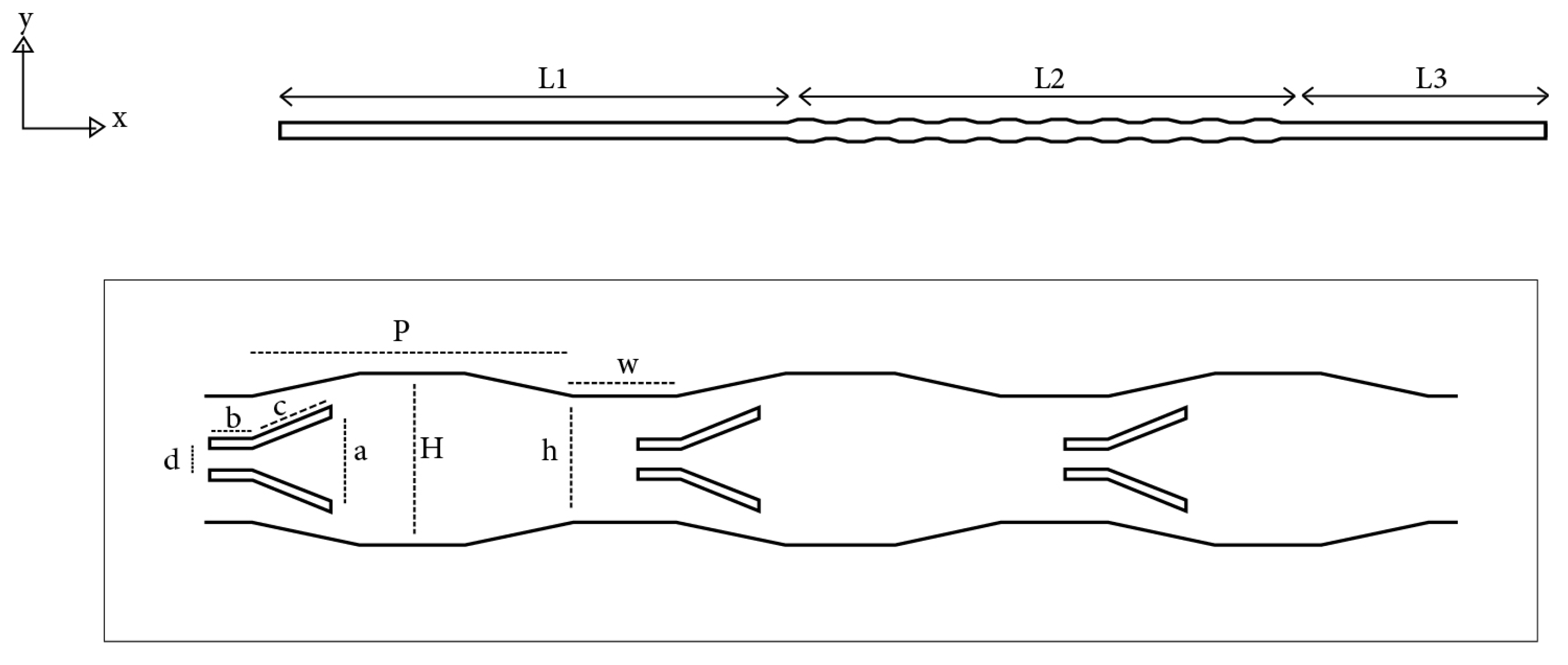
Figure 1 depicts the two-dimensional geometry of the schematic picture of the physical problem being investigated, which is a geometrical model of a trapezoidal corrugated channel. Corrugated channels frequently have two walls, one higher and one lower. The flow domain is separated into three areas: the test section, which has corrugated surfaces heated from above and below, and the downstream and upstream sections, which have smooth, flat surfaces that are handled adiabatically. The channel had an overall length of 500 mm and a corrugated section (L2) of 200 mm. To assure complete flow at the test component, the upstream or entry part was 200 mm (L1) and the downstream or exit section was 100 mm (L3). The entrance and exit channels have a height of
h = 6 mm. Corrugation’s pitch is (
p = 20 mm), while its width and height are
w = 15 mm and
H = 8 mm, respectively. Furthermore, channel dimensions and heating rate simulation conditions are taken into account in order to bring the simulation process as near to the genuine plate-fin heat exchanger design. The vortex generators are extruded along the channel depth (z-axis), resulting in symmetric flow behavior along this direction. Although a 2D simulation cannot fully capture the 3D secondary flows induced by the vortex generators, it approximates their effect by creating recirculation zones in the plane of the channel, allowing for an efficient estimation of heat transfer enhancement. The specific values of these parameters are summarized in
Table 2.
2.1. Governing Equations
The governing equations for a given geometry and set of boundary conditions are solved numerically using the CFD approach [
44,
47].
The continuity or conservation of mass, momentum, and energy governs the turbulent flow of nanofluids and forced convection heat transfer in a corrugated channel. The Reynolds-averaged Navier–Stokes (RANS) equation was modified for a 2D flow of an incompressible Newtonian fluid in a steady state. The following is a general Cartesian form for these equations.
The averaged Reynolds equations as well as the energy equation obtained reveal a number of additional unknowns (
), hence the need for a turbulence model in order to close the system of equations to be solved. In this sense, several turbulence models are available. For the present study, the choice fell on the most commonly used model: the standard (k–
) model. The k–
model is a two-equation model that uses the turbulent kinetic energy (
k) and dissipation (
) transport equations to provide a broad description of turbulence. The rate at which velocity fluctuations disappear is known as the turbulent dissipation. Based on the comparison between the exchange of momentum caused by turbulence at the macroscopic scale and molecule interaction at the microscopic size, this model employs the Boussinesq idea. The k–
model applies the gradient diffusion hypothesis to link Reynolds stresses with the mean velocity gradients and turbulent viscosity [
48].
where
and
are the turbulent Prandtl numbers for the turbulent kinetic energy and dissipation rate, respectively.
;
. Empirical coefficients are equal to
;
.
represents how average velocity gradients cause turbulence to produce kinetic energy.
2.2. Boundry Conditions
The following boundary conditions are subjected to the above equations:
At the channel entrance, the working fluid (water and nanofluids) enters at a uniform temperature (
T) is
. The inlet velocity is determined from the Reynolds number, which varies from 5000 to 17,500, according to
where
and
are the dynamic viscosity and density of the fluid, respectively. For the corrugated (trapezoidal) channel, the hydraulic diameter
D is estimated as
where
H is the main channel height and
h is the corrugation height, following the approach used in previous studies [
47].
Near the smooth and corrugated walls, the impermeability and no-slip conditions imply . The upstream and downstream smooth channel walls are assumed adiabatic, whereas in the corrugated section, a heat flux of is imposed.
To the output, the flow at the outlet is assumed to be hydrodynamically fully developed (, ) and thermally fully developed (), which ensures zero normal gradients for the velocity components and temperature.
2.3. Thermophysical Properties of Hybrid Nanofluid
With the proper changes, the equations provided in this paper may be used for both mono and hybrid nanoparticles. The symbols (bf), (np), and (nf) stand for the base fluid, nanoparticles, and nanofluid, respectively [
38]. The necessary characteristics of the
,
, and
water nanofluid for simulations were derived by applying the mixing theory, as shown below. The thermal and physical properties of these nanoparticles are listed in
Table 3. These equations are used to calculate the effective thermophysical properties of the nanofluid (density, viscosity, specific heat, and thermal conductivity). In the case of hybrid nanofluids, two types of nanoparticles are first combined using the mixing rules, and the resulting mixture is treated as an equivalent single nanoparticle with averaged properties. Once the equivalent properties are determined, they are inserted into ANSYS Fluent 2021 Fluent as input data for the numerical model. This approach allows both mono and hybrid nanofluids to be simulated consistently within the single-phase model. It should be noted that this single-phase model implements a mixture theory (or effective medium approximation) specifically for hybrid nanofluids. In this framework, the hybrid suspension is approximated as a single-phase fluid with effective properties derived from the constituent nanoparticles. This clarification ensures that the methodology accurately reflects the assumptions and limitations inherent in modeling hybrid nanofluids.
The density (
) of the equivalent nanoparticles is given as
The specific heat capacity (
) of the equivalent nanoparticles is given as
The thermal conductivity (
) of the equivalent nanoparticles is given as
The effective heat capacity [
50]:
Using the empirical correlation below, the influence of Brownian motion will be taken into account when computing the (
) while employing nanoparticles in the corrugated channel [
50]
where the Boltzmann constant is
and the values of
. The function
is given by
The effective viscosity [
51]:
The equivalent diameter of base molecule:
where the Avogadro number is
.
2.4. Numerical Method
The pressure-based Finite Volume Method is used to solve the governing equations. Pressure and velocity components are stored on a staggered grid, where pressure is located at the cell faces, while the velocity components are stored at the center of each cell. A SIMPLE method couples the pressure and velocity components [
52]. A second-order upwind differencing strategy was employed in order to discretize the governing equations [
53]. Lastly, it is considered that for the summing of residuals less than
, the solutions have converged (see
Appendix A for details on the numerical simulation procedure).
ANSYS Fluent plays a vital role in optimizing designs, improving performance, and tackling intricate fluid flow challenges. It predominantly employs the Finite Volume Method (FVM) to simulate fluid flow, heat transfer, and associated phenomena. This method involves discretizing the computational domain into control volumes and solving governing equations within them [
54,
55].
3. Mesh Independence Study and Validation
In general, the precision of numerical results hinges on mesh resolution. To ascertain the necessary element size for our study, six distinct mesh sizes were tested: 0.8, 0.6, 0.4, 0.2, and 0.1 mm. For water at Re = 5000, the velocity profile along the centerline of the fifth corrugation was evaluated for each case. Upon closer inspection,
Figure 2 shows that the grid sizes of 0.1 and 0.2 mm yield almost identical results, confirming mesh independence. Therefore, a grid size of 0.2 mm was selected as optimal to balance accuracy and computational cost. The number of nodes corresponding to each mesh size is summarized in
Table 4.
To assess the precision of numerical methods, the current study compares its results to those of the earlier investigation carried out by Shlash and Koç [
9]. This comparison study, as shown in
Figure 3, shows how average Nusselt numbers fluctuate in relation to Reynolds numbers for corrugated channels with vortex generators. It should be noted that there is consistency between the two sets of results. In addition, further validation was performed against the study by Ajeel et al. [
37], which investigated corrugated channels without vortex generators. This dual comparison strengthens confidence in our results, as it demonstrates agreement for both configurations (with and without vortex generators). To provide a more quantitative assessment of accuracy, error metrics were also calculated for the comparison with both benchmark studies. For the validation against Shlash and Koç (VGs case), the results yielded a Mean Absolute Percentage Error (MAPE) of 3.59%, a Root Mean Square Error (RMSE) of 8.45, and a coefficient of determination (
) of 0.996, indicating excellent agreement. Similarly, for the validation against Ajeel et al. (no VGs case), the corresponding metrics were a MAPE of 2.57%, RMSE of 4.57, and
of 0.991. These quantitative measures confirm that the present model is in strong alignment with established results and can reliably capture the heat transfer behavior of corrugated channels. Essentially, the averaged Nusselt values are established by
The convective heat transfer coefficient (
h) is obtained from the ANSYS Fluent simulation results.
Table 5 summarizes the error metrics, confirming excellent agreement with previous studies.
4. Results
4.1. The Effect of VGs
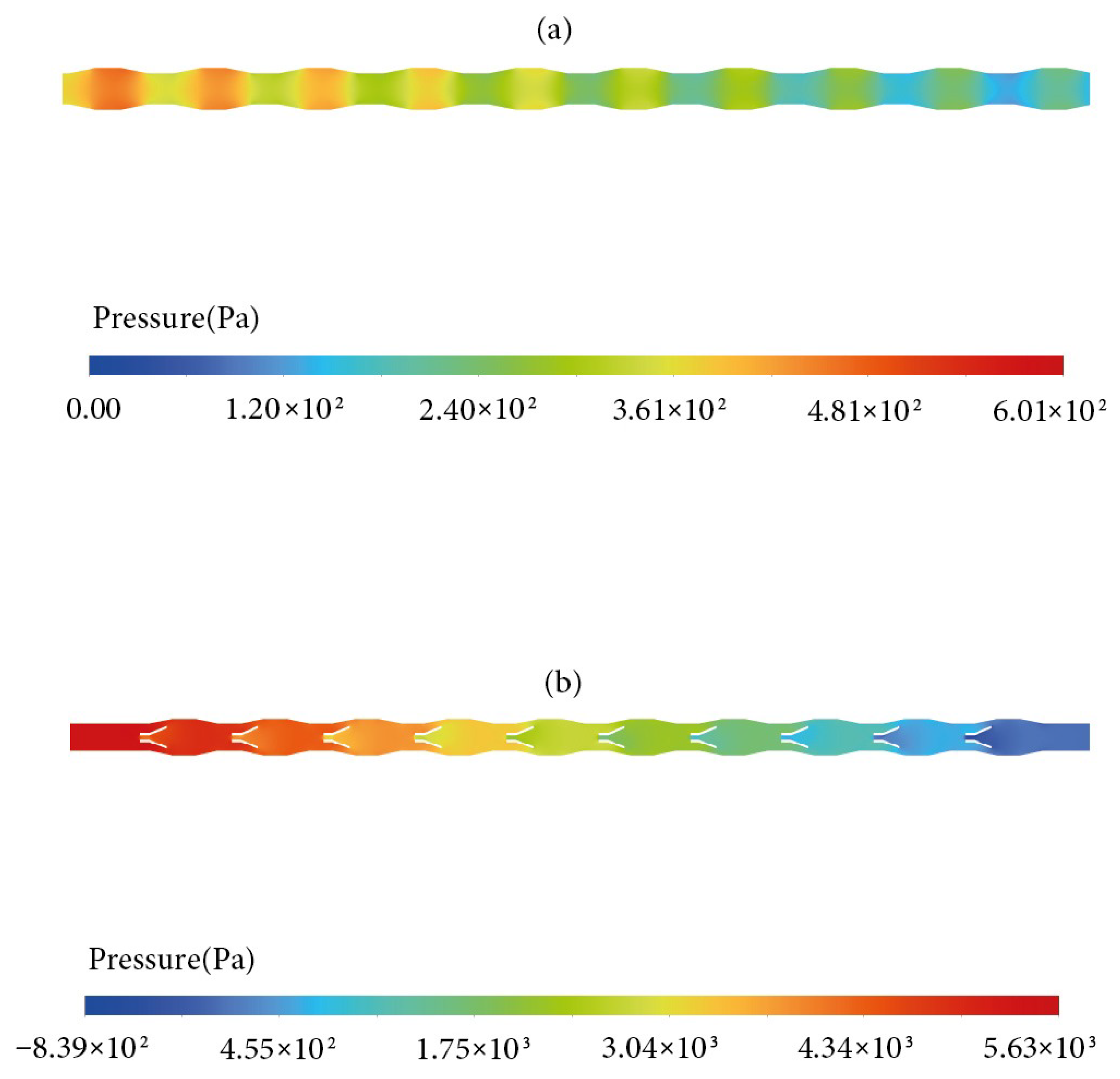
Figure 4 presents pressure contours, which are most noticeable at Reynolds numbers of 5000. Pressure reaches its maximum close to the entrance of the channel and then begins to decrease as one moves in the direction of the exit. The existence of corrugations along the surface of the channel contributes to a noticeable reduction in pressure, which is gradually intensified. The use of vortex generators considerably modifies this pressure profile even further. It should be noted that the present study employs a two-dimensional model, which cannot fully reproduce the three-dimensional vortical structures of actual VGs. Instead, the results reflect the approximate influence of VGs represented in 2D, primarily through modifications to flow recirculation and pressure distribution. Thus, the observed effects should be interpreted as indicative trends rather than exact quantitative predictions. The pressure is observed to be much higher at the entrance of the channel and noticeably lower at its departure, indicating significant changes caused by the vortex generators. The pressure distribution arises from viscous wall-shear losses and form drag caused by flow separation and reattachment over the corrugations and vortex generators. These mechanisms increase resistance to the flow, leading to the higher pressure drop observed. These outcomes highlight the significant impact that geometric arrangements have on the channel pressure. Furthermore, they emphasize how important it is to take these combinations into account when designing and improving fluid flow systems.
A velocity distribution contour field at a Reynolds number of 5000 is shown in
Figure 5. When corrugations without vortex generators are used, the fluid accelerates significantly toward the channel’s center, while velocities near the walls remain lower. The addition of winglet-shaped vortex generators inside the corrugations reduces stagnation areas close to the channel edges and redirects flow toward the middle of the channel. Although only winglet-shaped vortex generators are considered in this study, their presence significantly influences velocity streamlines and improves the flow distribution near the walls. The interaction between the surface layer and the viscous sub-layer explains the apparent decrease in velocity close to the walls, which is mitigated by the vortex generators. The resulting flow integration enhances heat transfer performance. For qualitative validation, the velocity contours obtained in this work are compared with those reported by the reference study [
56], and the close agreement further supports the accuracy of the present numerical model. This agreement increases confidence in the 2D approach for capturing overall flow redistribution trends. However, it does not replace full 3D validation, which would be necessary to fully resolve secondary vortex structures and spanwise effects.
Figure 6 provides a detailed representation of the x-velocity variation along the 5th corrugation line (x = 287.5 mm) across a range of y values from −7 mm to 7 mm, corresponding to a Reynolds number (Re) of 5000. This visualization underscores the significant influence of vortex generators (VGs) on fluid dynamics and heat transfer within the channels. Upon observing the velocity profile, it becomes apparent that the distribution of velocity follows a parabolic shape at the geometry’s center. However, the introduction of vortex generators brings about notable alterations to this profile. Notably, the velocity not only changes direction around the channel walls but also exhibits negative values in the channel’s center, attributed to the influence of these VGs. This observation further underscores their pivotal role in modifying flow behavior.
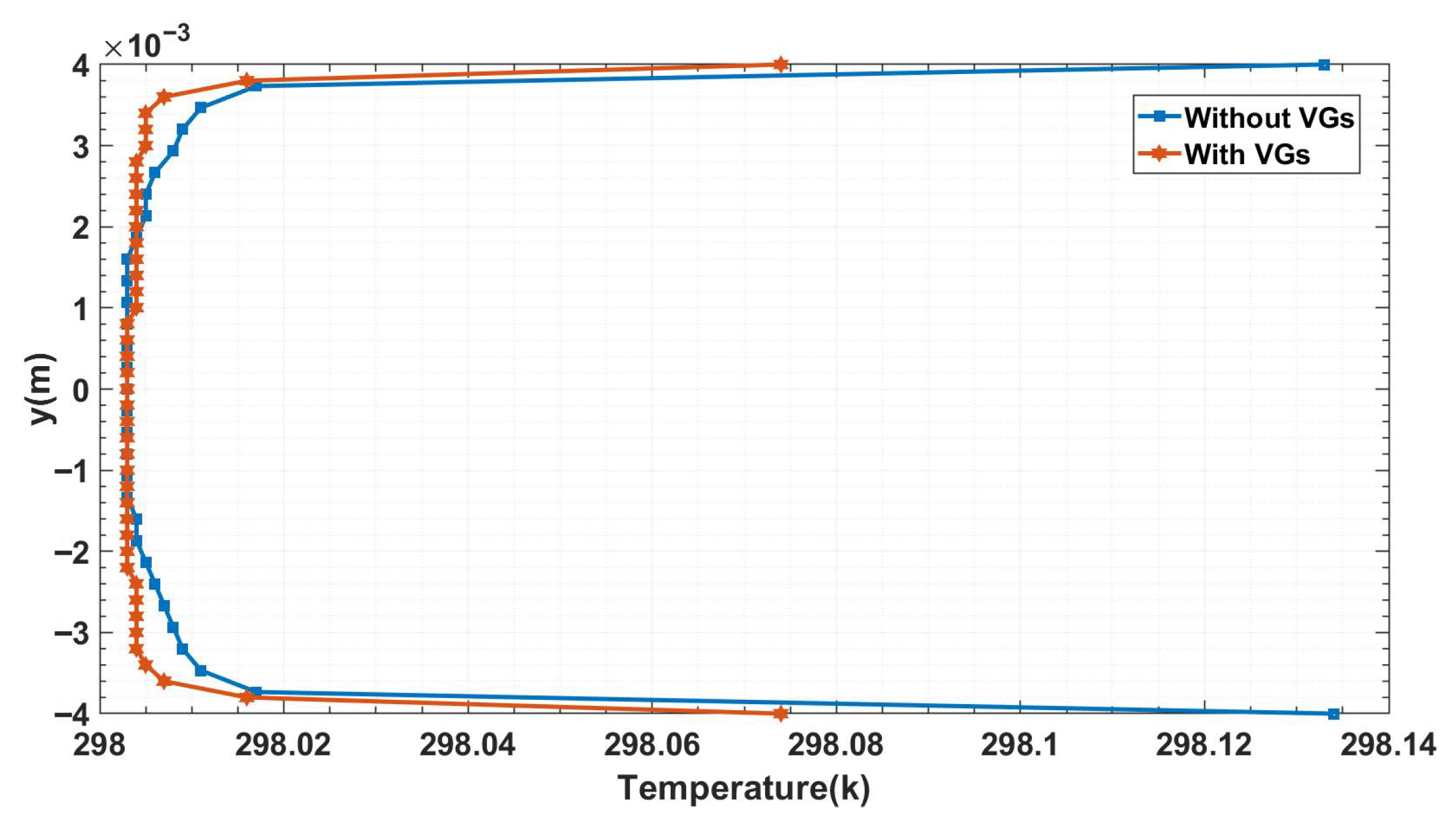
The temperature distribution along the fifth corrugation line (x = 287.5 mm) is significantly illuminated by
Figure 7. Although there are noticeable fluctuations in the fluid’s temperature, particularly in the vicinity of the channel walls, it is evident that a significant thermal boundary layer is present. There are noticeable temperature variations in this layer, which might make heat transfer procedures less efficient. Nevertheless, the incorporation of vortex generators (VGs) results in a significant decrease in these temperature differences. This reduction demonstrates how VGs disrupt and thin the thermal boundary layer through enhanced mixing and secondary vortices, which in turn improves the system’s total heat transfer efficiency. These results highlight the critical function of VGs in modifying temperature gradients, especially in configurations with naturally high gradients. This emphasizes the potential of VGs to enhance convective heat transfer in this 2D framework. Nevertheless, the absence of fully three-dimensional vortex dynamics means these findings represent approximate guidance rather than definitive quantitative conclusions.
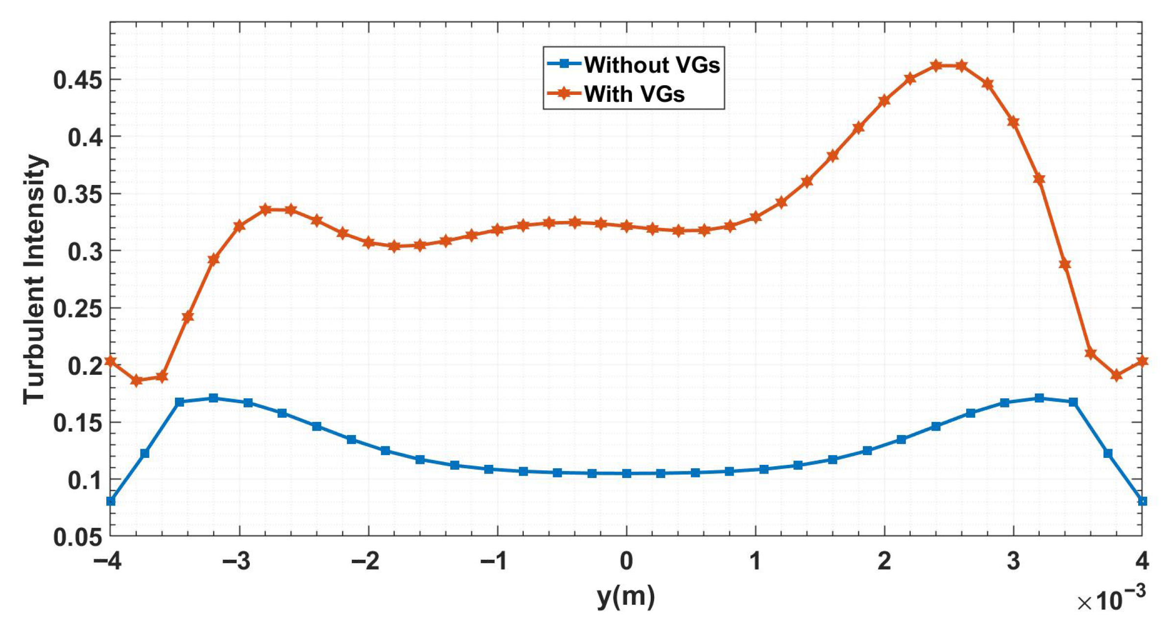
Figure 8 shows the turbulence intensity at Reynolds number (Re) 5000 in detail, with a focus on the corrugation’s centerline. A famous illustration shows the effect of vortex generators (VGs) on the distribution of turbulence intensity. In the absence of VGs, turbulence intensity is lower in the channel core and higher near the walls due to shear. With VGs, additional secondary flows and vortices are generated, which increase turbulence intensity and promote stronger mixing across the channel. This observation highlights the ability of VGs to increase turbulence and enhance fluid mixing, which directly affects the dynamics of flow and heat transfer inside the channel. Because turbulence production and secondary vortices are inherently three-dimensional, the present results should be viewed as qualitative indications of the trend rather than precise turbulence distributions.
4.2. The Single Nanofluid
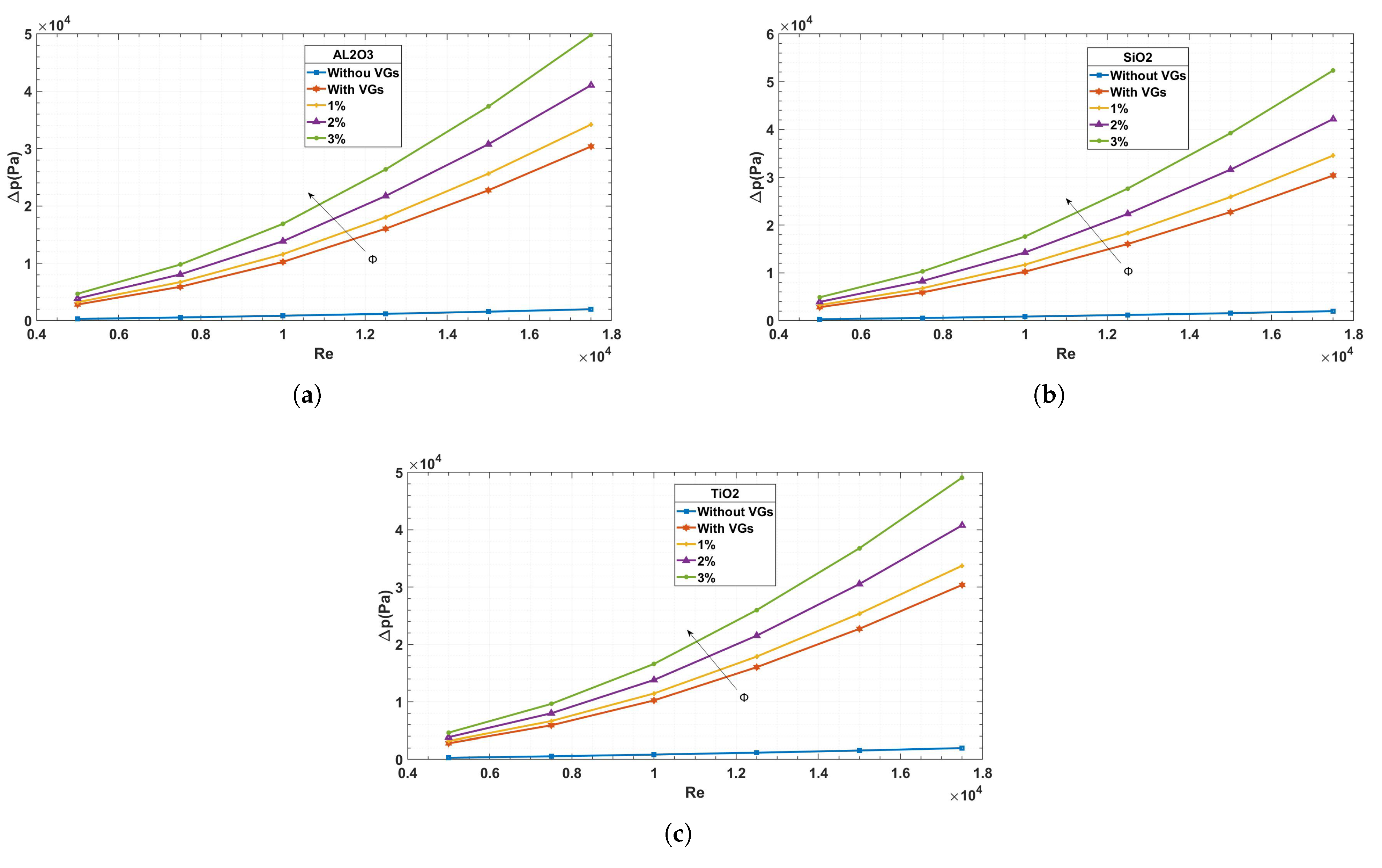
A detailed comparison of the pressure gradients in channels with and without vortex generators (VGs) at different Reynolds numbers and with three different types of nanofluids is shown in
Figure 9. This graphic makes clear how VGs affect pressure gradients; when VGs are used, the gradient is significantly less than when they are not used. Additionally, a pattern becomes apparent, suggesting a direct relationship between Reynolds number and pressure gradient. This association emphasizes how flow behavior is dynamic and how Reynolds number variations are crucial. The pressure gradients for each of the three types of nanofluids converge with lower Reynolds numbers. But as the Reynolds number rises, distinct variations in pressure drop become apparent, which are further enhanced by different volume concentrations. Significantly, a higher concentration of nanofluid is associated with a greater pressure drop; this decrease is even more noticeable when VGs are added. This finding is explained by the fact that higher volume concentration nanofluids have a higher viscosity, which causes a more noticeable drop in pressure.
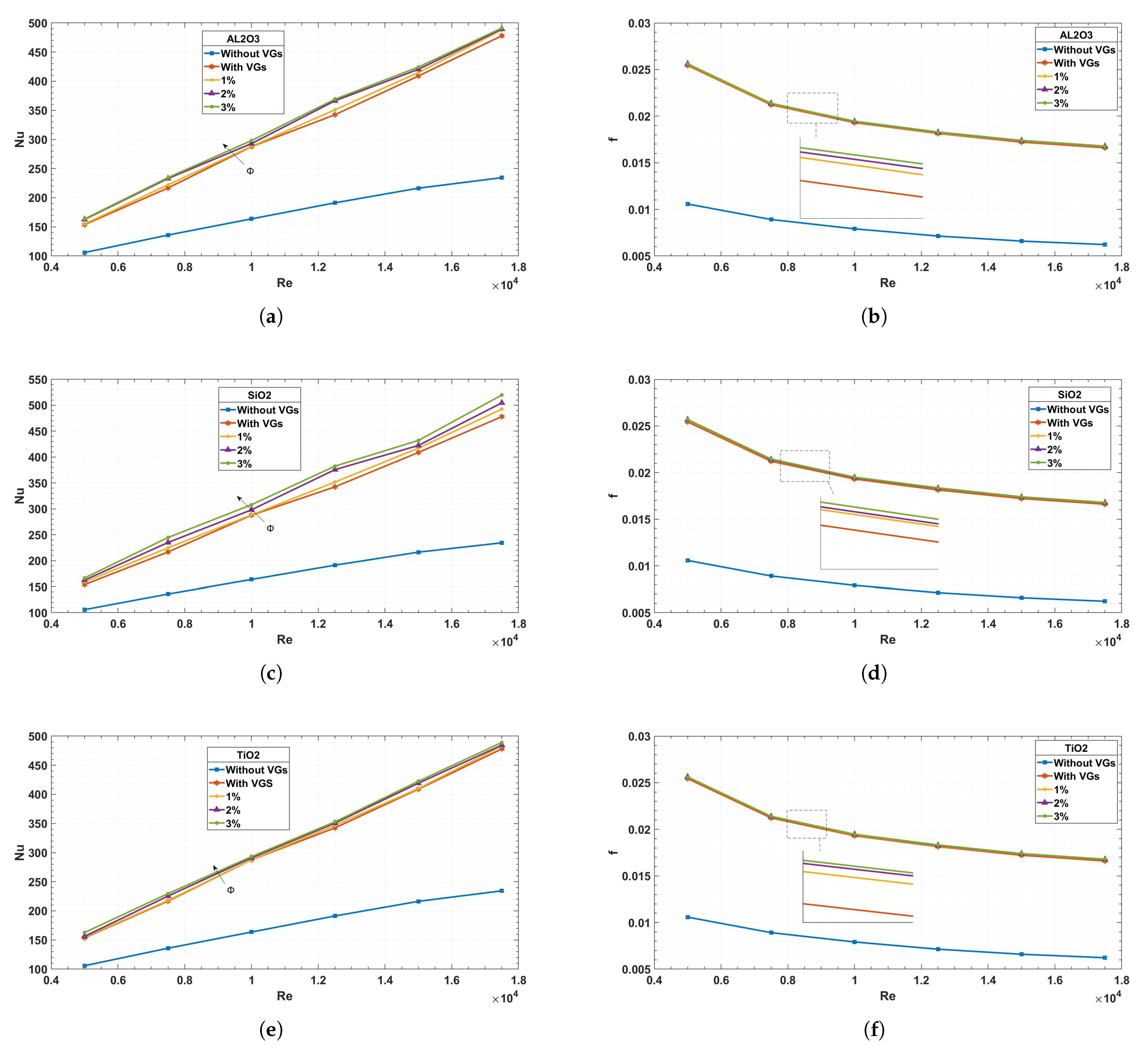
Figure 10: the study conducted here investigates the variations in the Nusselt number and friction coefficient in relation to the Reynolds number, with and without the utilization of vortex generators (VGs), across three types of nanofluids. The analysis underscores the significant influence of Reynolds number on the Nusselt number, shedding light on the complex interplay between flow dynamics and heat transfer characteristics.
Moreover, a notable observation emerges concerning the friction coefficient, contrary to anticipated trends, displaying an increase. This unexpected behavior is attributed to the heightened velocity gradient near the wall, intensifying frictional effects. In scenarios devoid of VGs, there is a tendency for the Nusselt number and friction coefficient to converge. However, upon the incorporation of VGs, a marked increase is observed in both parameters.
Furthermore, the impact of volume concentration on the thermal field becomes apparent. With each increase in concentration, there is a discernible rise in the Nusselt number, particularly pronounced in –water and less so in –water. Correspondingly, friction factor also demonstrates an increase, albeit less noticeably, with –water exhibiting higher values and –water lower ones. –water, on the other hand, displays moderate values in both parameters compared to the other two types.
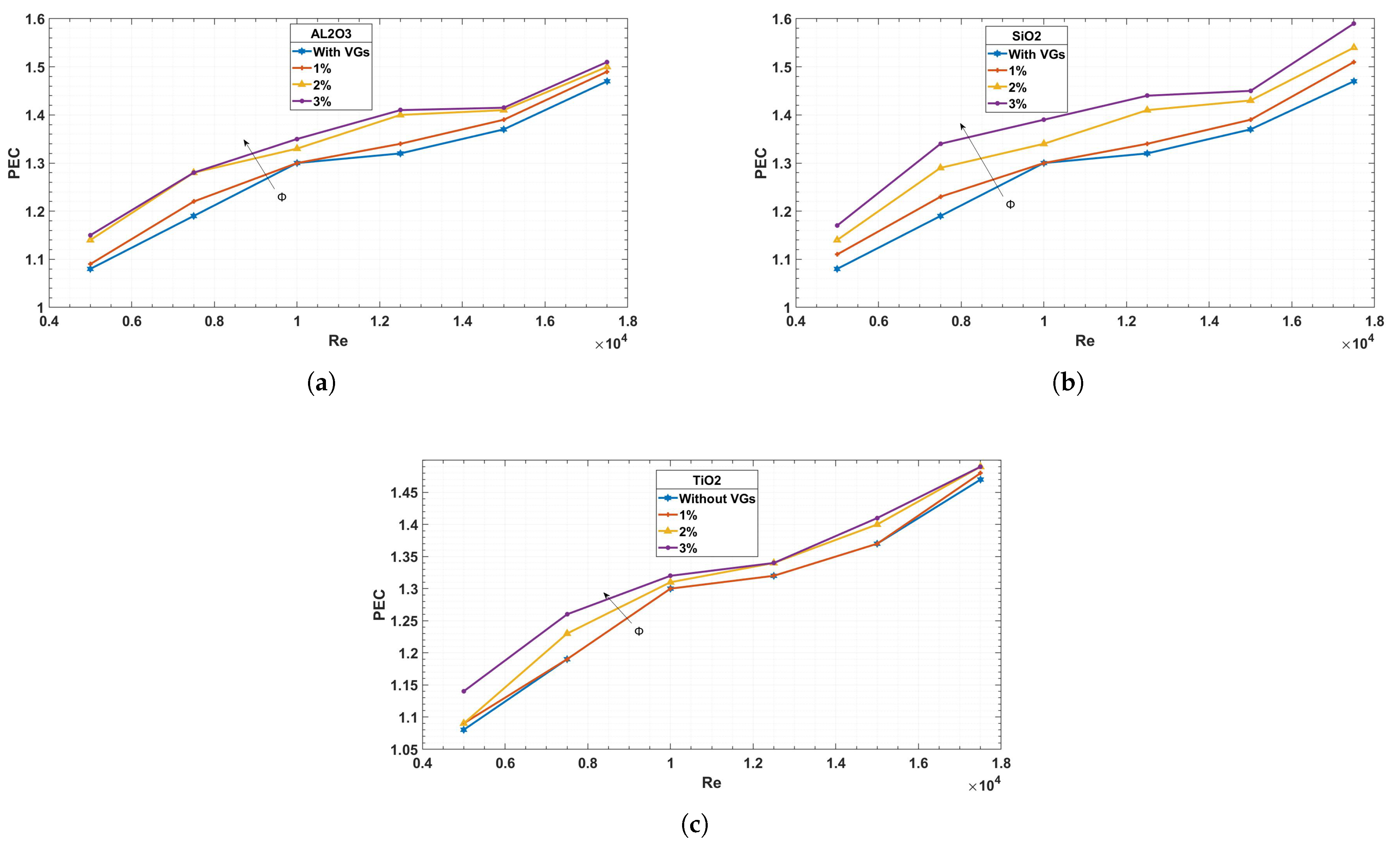
The ratio of the Nusselt number with the vortex generator to that without, with respect to the friction with and without the vortex generator, is the performance criterion PEC, as shown in
Figure 11.
This research indicates a significant tendency wherein the Reynolds number rises in tandem with the performance requirement. Moreover, the performance criteria is greater than unity, suggesting that vortex generators (VGs) are more beneficial than detrimental.
It is clear from comparing the three concentrations that the greater concentration especially in shows the greatest enhancement, which is noticeably more significant than in and .
To determine which kind of nanoparticle is best for improving heat transmission, three different nanoparticle compositions will be compared, with each nanoparticle concentration being 3%. The purpose of this comparative analysis is to clarify any appreciable variations in heat transfer efficiency that can be linked to the different nanoparticle compositions. Through a methodical evaluation of the heat transfer properties displayed by nanoparticles with different compositions at the same concentration, this investigation aims to offer significant insights into the relative effectiveness of each type of nanoparticle. These kinds of insights are essential for developing the best tactics for selecting nanoparticles that maximize heat transfer enhancement in real-world engineering applications.
The impact of various nanofluid types on temperature profiles and x-velocity profiles is shown in
Figure 12. This graphic illustrates how heat transmission and fluid dynamics within the channels are affected by nanofluids.
The velocity profile indicates that the increased viscosity of nanofluids causes the velocity to increase in the vicinity of the channel walls. Notably, due to the convergence of their nanoparticle properties, and nanofluids show comparable effects. nanofluids, on the other hand, exhibit greater velocity values, suggesting a major influence on flow behavior. This finding emphasizes how important nanofluids are in changing the properties of flow.
The use of nanofluids also makes temperature changes clear. Particularly for , the temperature differential around the walls reduces, but behaves nearly identically. , on the other hand, does not exhibit the same decrease in temperature differential as the other two varieties. However, temperature variations are reduced overall when nanofluids are used. This decrease shows how well nanofluids work to reduce the thermal boundary layer and improve the system’s overall heat transfer efficiency.
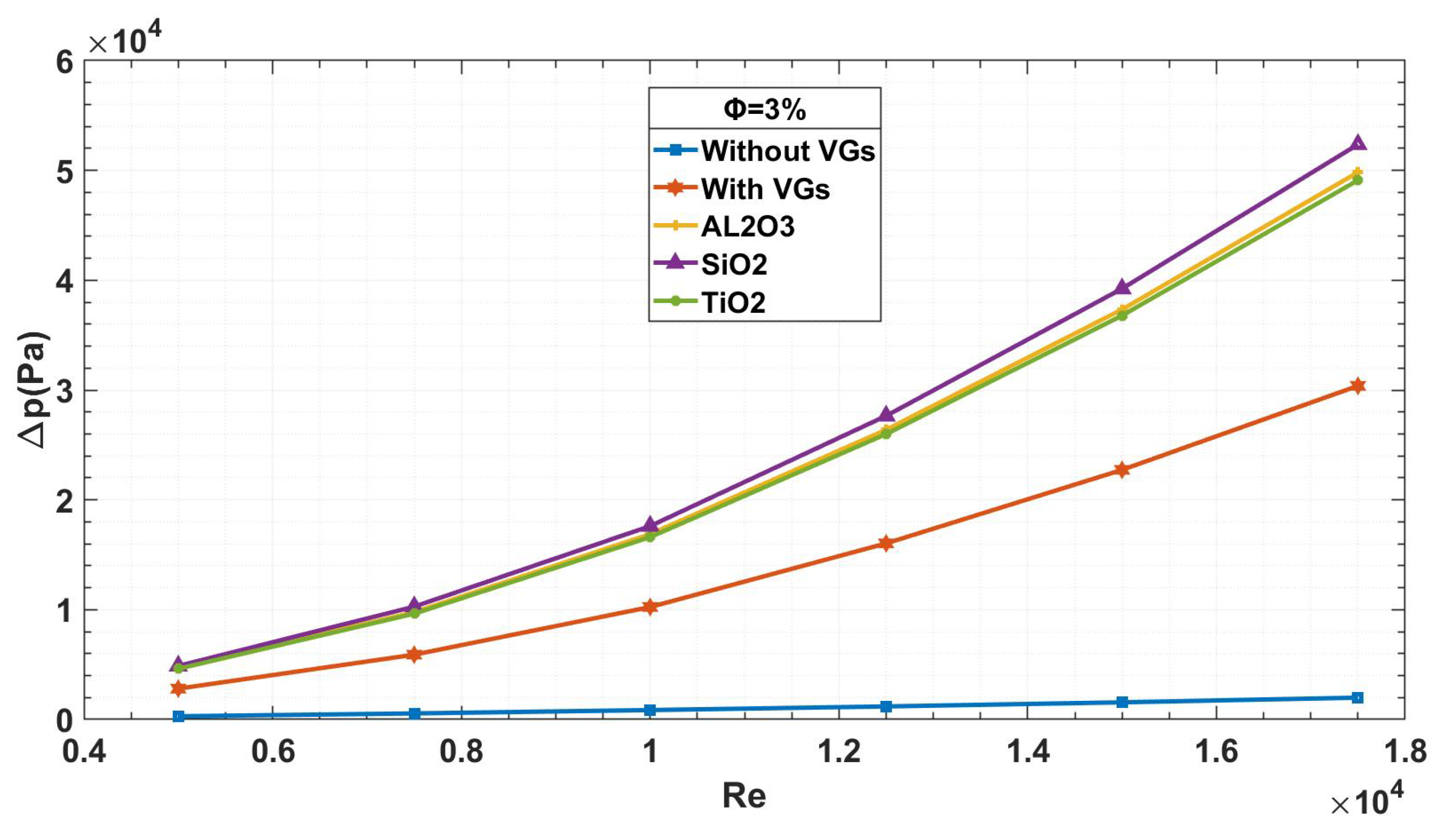
Figure 13 presents a comparison between different types of nanofluids. All three types show almost same values at lower Reynolds numbers. However, as the Reynolds number rises, the nanoparticles’ behavior changes, resulting in noticeable variations. In particular, using nanofluids results in an increase in the pressure gradient. While
nanofluids experience a greater pressure drop than the other two varieties,
and
nanofluids behave similarly when it comes to pressure gradients.
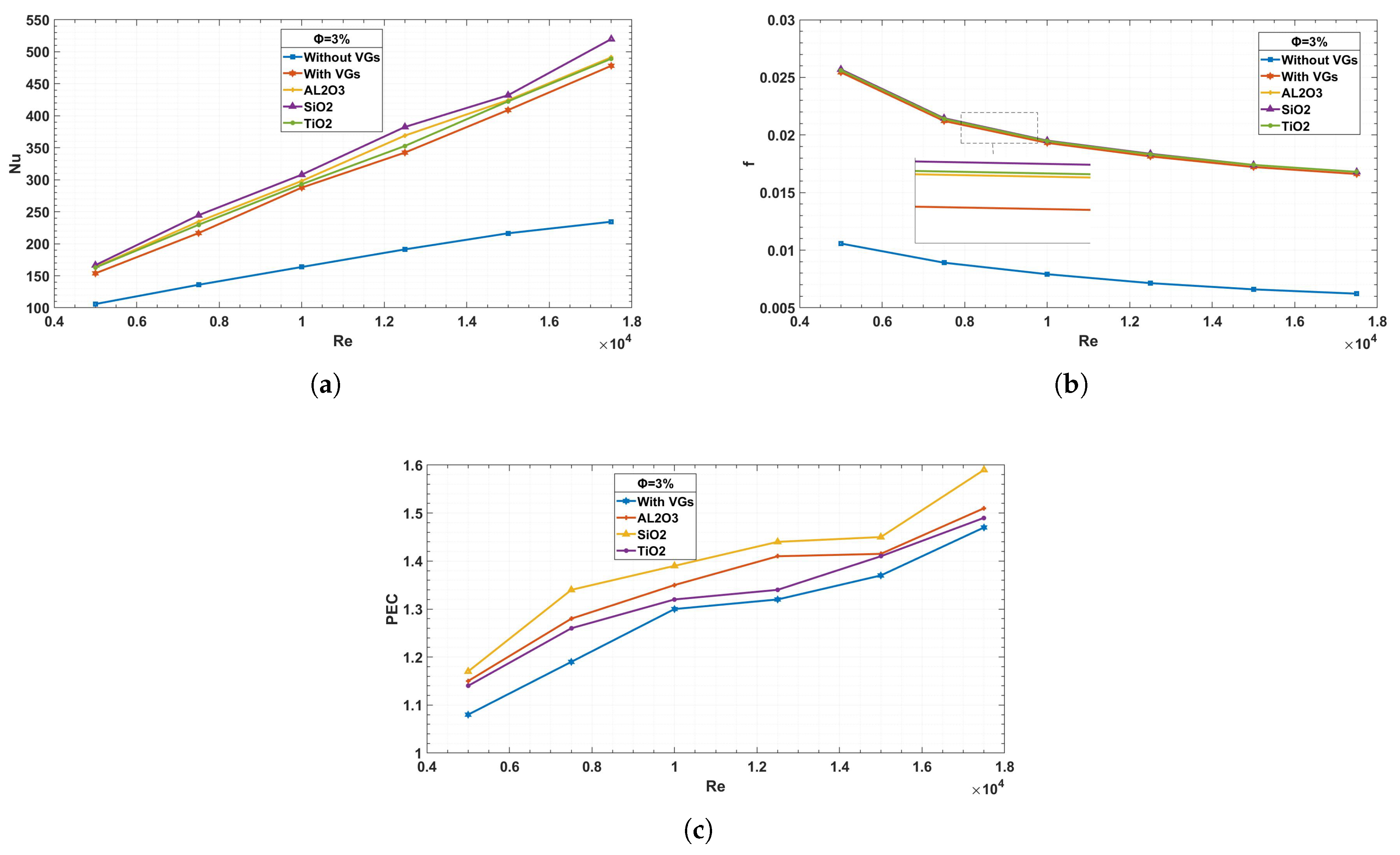
Figure 14 illustrates a comparison of the Nusselt number, friction coefficient, and thermal performance coefficient among three types of nanofluids as a function of Reynolds number. While
exhibits the highest Nusselt number; this result is not due to its intrinsic thermal conductivity (which is lower than that of
and
) but rather to its lower density and reduced viscosity penalty. These properties enhance flow velocity and convective transport, leading to higher heat transfer, as also reported in previous studies [
22].
shows performance comparable to
, consistent with their closer thermophysical properties. Overall,
achieves the best thermal performance coefficient under the present conditions, reflecting the combined effect of transport properties and flow dynamics.
4.3. The Hybrid Nanofluid
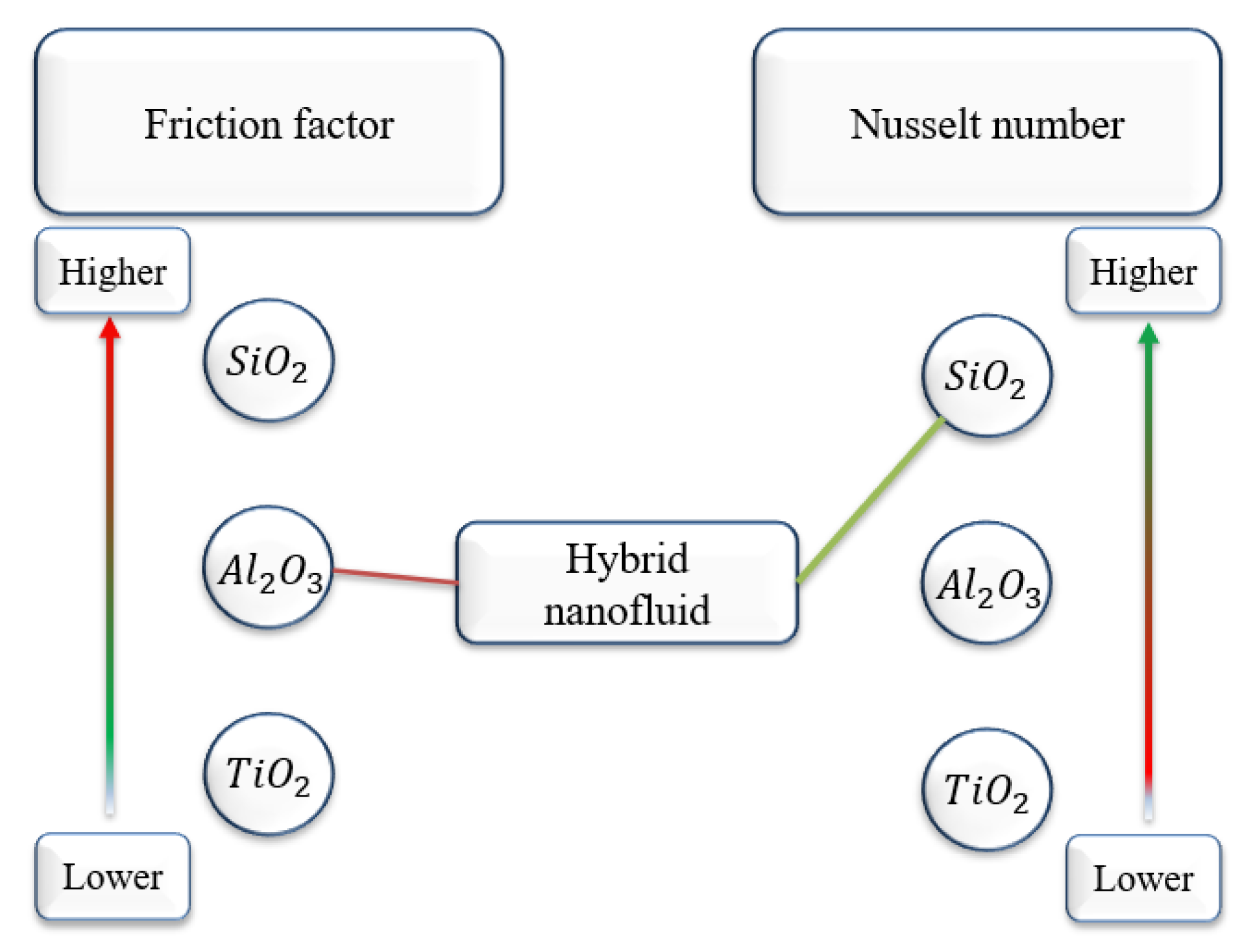
Figure 15 presents the scheme for the Nusselt number and friction factor, serving as a foundation for the next step, which involves hybrid nanofluids. By combining
, which demonstrates excellent heat transfer properties, with
, which has lower energy loss, we can create a hybrid nanofluid that offers both superior heat transfer and reduced energy loss. The hybrid nanofluid method involves mixing two types of nanoparticles in a single base fluid. In our study, we selected
as the first type and
as the second type. This choice is based on the explanation in
Figure 15 and the obtained results. We investigated three cases, each using different proportions of each type of nanoparticle while maintaining a total volume concentration of 3%. The specific volume concentrations for each case are summarized in
Table 6.
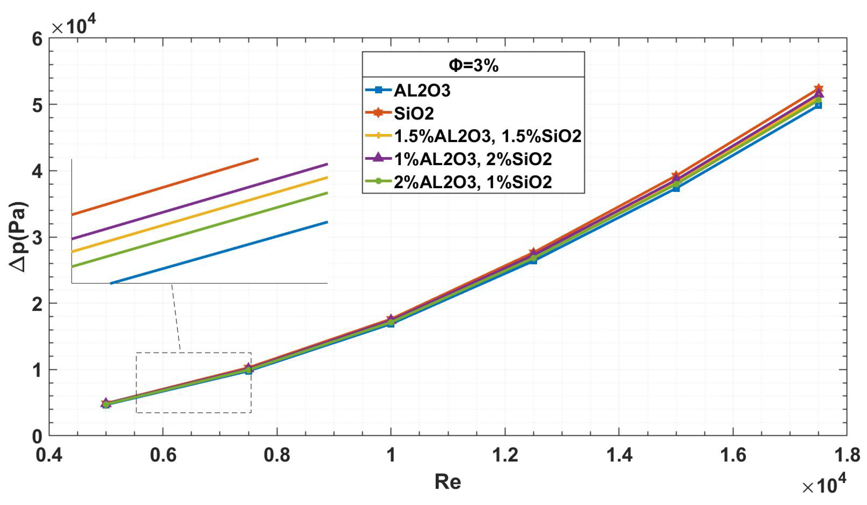
Figure 16 shows the pressure drop for the three cases of hybrid nanofluids. It has been noted that pure
has the largest pressure drop, whereas pure
has the lowest. Between these two extremes are the three hybrid cases. The pressure drop is greater than that of pure
but lower than that of pure
in the first scenario, where equal amounts of both types are utilized. The pressure drop rises with increasing
concentration and approaches the value of pure
. On the other hand, as the concentration of
increases, the pressure drop reduces and approaches the value of pure
. This illustrates how
can be added to hybrid nanofluids to impart its characteristics and lower the pressure drop.
Figure 17 illustrates the Nusselt number, friction coefficient, and thermal performance coefficient for the three cases of hybrid nanofluids. When nanoparticles are combined, the Nusselt number rises relative to solitary nanoparticles; this is especially true in the second case where SiO2 is the predominant type. The Nusselt numbers in the other two examples also show improvements, suggesting better heat transport.
The friction coefficient, which has the highest values for pure and the lowest for pure , illustrates the impact of pressure drop. The predominant nanoparticle type in the hybrid nanofluid has a major effect in every case. Raising the percentage of causes friction to increase, but increasing the percentage of causes friction to decrease. The thermal performance coefficient shows the highest values in the second case, where is predominant in the hybrid nanofluid. This indicates that while enhances heat transfer, helps reduce friction, resulting in an optimal balance of thermal performance.
Table 7 compares the PEC values obtained in the present study with those reported by Their et al. [
56]. It is evident that the use of hybrid nanofluids and vortex generators in the present study enhances thermal performance, with PEC increasing up to 1.60 at Re = 17,500, compared to a maximum PEC of 1.49 in the reference study. This demonstrates that the proposed configuration effectively improves heat transfer while maintaining pressure drop at acceptable levels, highlighting the added benefit of combining hybrid nanofluids with corrugated channels and vortex generators. For consistency, the values from Their et al. [
56] at Reynolds numbers 7500, 12,500, and 17,500 are interpolated from their reported data, while the remaining values are taken directly from their study.
It is important to note that the performance evaluation criterion (PEC) simultaneously accounts for both heat transfer enhancement (via the Nusselt number) and the associated increase in pressure drop (via the friction factor). Since the PEC values obtained in all cases are greater than 1, this confirms that the improvement in heat transfer outweighs the penalty of pressure drop, indicating that the pressure drop remains within an acceptable range.
5. Conclusions
The present work represents a two-dimensional numerical study that approximates the influence of vortex generators (VGs). As such, the observed results indicate qualitative 2D trends rather than exact quantitative predictions of real 3D VG performance. As such, the results highlight indicative trends, but they do not fully capture the three-dimensional vortex structures produced by real VGs. In this work, three different nanofluids—, , and —were used to simulate flow and heat transfer processes in a corrugated channel equipped with VG-shaped obstructions. Reynolds numbers between 5000 and 17500 were examined using the Finite Volume Method. This study investigated the effects of VG-shaped obstructions, nanoparticle volume concentration, and the additive effect of mixing nanoparticles on temperature and flow parameters. The main findings of this study are summarized as follows:
A clear relationship exists between Reynolds number and both thermal and flow characteristics. Recirculation zones form along the walls of the corrugated channel, and the observed 2D trends suggest that VG-shaped obstructions drive the flow toward these walls, reducing the thermal boundary layer thickness. Although VG-shaped obstructions appear to enhance heat transfer, they also increase fluid stagnation and pressure drop, highlighting the need to balance heat transfer improvement with pressure loss.
Turbulence intensity near the channel walls increases due to viscosity effects, while 2D approximations of vortex generators may redistribute turbulence, reducing it in the core region and enhancing it near the walls. Using nanofluids increases both the friction coefficient and the Nusselt number. Among the three nanoparticles, yields the highest average Nusselt number and friction coefficient, the lowest, and shows intermediate values. Increasing nanoparticle volume fraction further improves these thermal and flow properties.
Hybrid nanofluids combining two types of nanoparticles demonstrate enhanced performance, though it should be noted that the present study relies on linear empirical mixing models, which approximate but may not fully capture the complexity of hybrid suspensions. Within this framework, the properties of the dominant nanoparticle largely determine the overall behavior. For instance, the mixture of and
appears to leverage ’s favorable convective contribution while mitigating frictional losses with . The performance evaluation criterion (PEC) indicates that nanofluids improve thermal performance across all Reynolds numbers. In particular, the hybrid nanofluid achieved a maximum PEC of 1.6 at Re = 17,500, demonstrating significant improvement over single-type nanofluids. Thus, while hybrid nanofluids appear promising, these results should be interpreted as trend-level insights, and further validation with non-linear or experimentally based property models is needed to confirm these trends.
Limitations
This study is limited by the use of a single-phase nanofluid model and empirical correlations to estimate thermophysical properties, which may not capture all microscale particle–fluid interactions. Only three types of nanoparticles (, , ) and concentrations up to 3% were considered, and the simulations were restricted to flow using ANSYS Fluent 2021. This simplification means that the characteristic three-dimensional vortices of vortex generators are not explicitly resolved; therefore, the present results should be interpreted as trend level insights rather than precise quantitative predictions of VG performance. Additionally, the validity of the correlations used for hybrid nanofluids is an area of ongoing research and uncertainty; the results are therefore contingent on the accuracy of these specific empirical models and should be interpreted accordingly. Experimental validation under identical conditions was not performed. Future work could extend to three-dimensional simulations, higher nanoparticle concentrations, and direct experimental studies to confirm the numerical predictions.
