Abstract
We present a crack-free optically active SiO2 glass-composite material containing YAG:Ce synthesized via a modified sol–gel technique. A glass-composite material consisting of yttrium aluminum garnet doped with Ce3+ (YAG:Ce) was entrapped into a SiO2 xerogel. This composite material was prepared using a sol–gel technique with modified gelation and a drying process to obtain crack-free optically active SiO2 glass. The concentration of the YAG:Ce was from 0.5 to 2.0 wt%. All synthesized samples were characterized via X-ray diffraction (XRD) and scanning electron microscopy (SEM) techniques, confirming their exceptional quality and structural integrity. The luminescence properties of the obtained materials were studied. Overall, the prepared samples’ excellent structural and optical quality makes them great candidates for further investigation, or even potential practical application. Furthermore, boron-doped YAG:Ce glass was synthesized for the first time.
1. Introduction
For a long time, sol–gel techniques have been used for the fabrication of glasses and ceramics. Sol–gel synthesis is a widely used method for the preparation of glasses. This method involves the creation of a sol, which converts into a gel and then a glass upon thermal treatment. The sol–gel process can produce glasses with various compositions and structures, making it a versatile and flexible technique. One of the advantages of sol–gel synthesis for glass production is its ability to create complex systems with high surface areas and uniform morphology. The process allows for precise particle size, shape control, and consistent glass properties and performance. In addition to offering a cost-effective and scalable approach to glass production, sol–gel synthesis is a sustainable method with a low cost and environmental impact [1,2,3,4,5]. Due to its significant contributions, the sol–gel method is widely acknowledged as a key technique within the mentioned field. It has demonstrated great success in producing nano powders, encompassing oxide, non-oxide, and composite varieties. Furthermore, the sol–gel process promotes the preparation of highly pure materials [6].
The sol–gel technique of preparing glasses is still being studied. Glasses synthesized via the sol–gel method have attracted much interest because of the possibility of synthesizing glass components, for example, optical fibers, lenses, mirrors, etc. Optically active SiO2 glasses are a fascinating class of materials due to their interesting optical properties and potential applications in various fields. A small amount of dopant ions causes the optical activity of SiO2 glasses. Optically active SiO2 glasses have several potential applications in optics and photonics. For example, they can be used in polarization-sensitive optical devices such as polarizers, waveplates, and optical rotators. They can also be used in sensing applications, where changes in optical activity can be used to detect chemical or biological molecules. Optically active SiO2 glasses represent a fascinating and rapidly evolving field of research with significant potential applications in optics, photonics, sensing, and fundamental science. SiO2 glasses have proven helpful as host materials for rare-earth ions in solid-state lasers. For several practical reasons, glasses doped with Nd3+ have found the most comprehensive application. Among other rare-earth-containing materials, Er3+-doped glasses are currently generating much interest as fiber amplifiers in optical communications systems [7,8,9,10].
White LED technology is based on blue LED chips, which were first developed by Nichia Co. in 1991. These chips are coated with yellow-emitting phosphor to create white light. One popular phosphor used for this purpose is Ce3+-doped YAG phosphor. This phosphor has been available since the 1960s, but it is considered a cool-light phosphor due to the lack of a red component in its emission spectrum. Its emission spectrum can be shifted by substituting the Y3+ or Al3+ with different ions. For example, replacing Y3+ with rare-earth ions such as Tb3+, Gd3+, Dy3+, La3+, etc. can introduce a red-shift, while substituting Al3+ with ions like Ga3+ or In3+ can cause a blue shift in the cerium emission. Co-doping with ions such as Pr3+ can also introduce a secondary peak in the red spectral range. White light-emitting diodes (wLEDs) with improved optical properties can be developed by co-doping a YAG:Ce phosphor with rare earth ions. Moreover, adjusting the Ce3+ concentration or modifying the process parameters can introduce a slight red shift in the emission spectrum. All this research has led to the development of highly efficient and versatile white LED technology [11,12,13,14,15,16].
Commercially available wLEDs typically combine Y3Al5O12:Ce3+ yellow phosphor, an InGaN-based blue-emitting LED chip, and epoxy resin for encapsulation. However, this conventional approach suffers from inadequate red emission, leading to poor color rendering and an improper color temperature. Consequently, the practical applications of these wLEDs in advanced lighting technologies are limited [17,18]. Moreover, phosphor-resin-based LEDs are subject to certain drawbacks. These include resin degradation over time due to current flow and differences in refractive indices between phosphors and epoxy resin, resulting in photon scattering and reduced emission intensity. These issues negatively impact the optical performance of the device, affecting aspects such as color purity and coordination. To overcome these limitations, novel phosphor-in-glass (PiG) color converters have been developed. These converters embed the phosphor material within a glass host through a sintering processes. However, PiG materials have drawbacks, including scattering losses attributed to their porous structure and the potential for reactions between the phosphor material and the glass host [19,20,21]. Based on the reasons above, this study presents a novel PiG composite. The composite is based on cerium-doped YAG and SiO2 glass fabricated using the sol–gel method. The sol–gel approach was selected due to its ability to achieve atomic-level mixing of ions, resulting in a homogeneous material at lower temperatures. Silica glass was chosen to prevent any undesirable reactions among the constituents. X-ray diffraction was utilized to ensure the phase purity of the composite. Luminescence properties were investigated to analyze the interface interactions between the phosphor and glass matrix. Finally, SEM analysis was conducted to examine the composite’s morphology and the distribution of the phosphor within the matrix.
2. Results and Discussion
2.1. X-ray Diffraction
The synthesized samples were analyzed via XRD analysis to determine their composition and purity. All peaks were identified. All reflexes were assigned to the garnet phase (YAG COD ID #1529037). The presence of a broad peak between 20 and 30° serves as a distinctive characteristic of the amorphous SiO2, acting as its unique identifier. Notably, there are no shifts observed in the XRD data, which means that no changes were made during the annealing to the pure garnet crystal phase. It can be stated that YAG:Ce@SiO2 composite samples are pure. The lattice parameter of doped garnet was refined, which was 12.0234 Å. In comparison with undoped garnet (11.99 Å, COD ID # 4312142) the lattice parameter increased, which confirms the incorporation of larger cerium cations in yttrium positions. The XRD patterns of the YAG:0.5%Ce@SiO2 composite and YAG:0.5%Ce are presented in Figure 1.
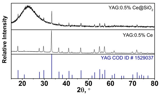
Figure 1.
XRD patterns of the 0.5%YAG:0.5%Ce@SiO2 composite and YAG:0.5%Ce.
2.2. Scanning Electron Microscopy (SEM) Analysis
SEM analysis was performed to determine the surface morphology of the synthesized composites. All synthesized samples were analyzed in different magnifications (I–25 k; II–5 k). Upon examination, it was observed that the surfaces of the samples appeared smooth, albeit with some noticeable microcracks. Within these microcracks, individual garnet particles were visibly present. Notably, these particles exhibited an interconnected structure with irregular shapes. It is worth mentioning that no significant variations were observed among the different samples. Most of the particles are in the size range between 200 to 700 nm. SEM images are presented in Figure 2.
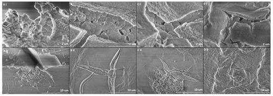
Figure 2.
SEM images of the samples in different magnifications. 0.5%YAG:0.5%Ce@SiO2 (A(I,II)), 1.0%YAG:0.5%Ce@SiO2 (B(I,II)), 1.5%YAG:0.5%Ce@SiO2 (C(I,II)) and 2.0%YAG:0.5%Ce@SiO2 (D(I,II)).
2.3. Luminescence Properties
The emission spectra of synthesized samples excited at 458 nm are depicted in Figure 3. In emission spectra, all samples have a wide band with a peak wavelength (λmax = 538 nm), which is attributed to the [Xe]5d1 → [Xe]4f1 electron transitions. Increasing the concentration of YAG:0.5%Ce leads to an increase in the emission intensity (Figure 3A). This may be due to an increase in the number of optically active centers in the samples as the concentration increases. Normalized luminescence spectra of YAG:0.5%Ce doped samples are shown (Figure 3B). The spectra exhibit a broad band from around 460 nm to 750 nm, with the maximal intensity at about 538 nm. Notably, the spectrum of the 0.5%YAG:0.5%Ce@SiO2 sample is slightly shifted to the shorter emission wavelength. It could be described as coupling the 5d levels with the surrounding crystal field [15,22,23,24,25].
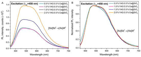
Figure 3.
Photoluminescence emission spectra of the samples. Emission spectra of 0.5%YAG:0.5%Ce@SiO2, 1.0%YAG:0.5%Ce@SiO2, 1.5%YAG:0.5%Ce@SiO2 and 2.0%YAG:0.5%Ce@SiO2 (A), normalized emission spectra of 0.5%YAG:0.5%Ce@SiO2, 1.0%YAG:0.5%Ce@SiO2, 1.5%YAG:0.5%Ce@SiO2 and 2.0%YAG:0.5%Ce@SiO2 (B).
The photoluminescence quantum yield (PLQY) was calculated. The quantum yield of the analyzed samples is shown in Table 1. The highest luminescence quantum yield value (23%) was observed in the samples doped with 1.5% YAG:0.5%Ce and 2% YAG:0.5%Ce. For other samples, it was lower.

Table 1.
The quantum yield of the analyzed glass samples.
Another fundamental analysis for optically active glasses is also the decay time measurements. Luminescence properties were further investigated by measuring the photoluminescence decay curves of the synthesized samples. All the analyzed samples exhibit bi-exponential photoluminescence decay. In Figure 4C, luminescence decay kinetics with 342 nm are shown. The luminescence decay of samples doped with 1–2% YAG:0.5%Ce exhibits similar properties, while in a sample with 0.5% YAG:0.5%Ce, the luminescence intensity decreases faster. Excitation and emission (Figure 4A,B) spectra were also measured. Based on the excitation spectra, it is clear that all compounds have wide bands at 342 and 460 nm wavelengths. It can be observed that the most intensive excitation at 342 nm has 0.5%YAG:0.5%Ce@SiO2. This could be related to the relative decrease in the green 550 nm luminescence band in the 0.5% YAG:0.5%Ce doped sample (Figure 4B). All the decay curves were calculated and approximated with a double exponential function: A1 and A2 are the fitting parameters, τ1, and τ2 are decay times of the fast and slow decay components. Using τ1 and τ2, the average lifetime was calculated using Equation (1):
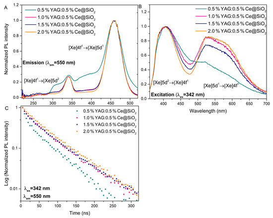
Figure 4.
Photoluminescence excitation (A), emission (B) spectra, and decay curves (C) of glass samples.
The calculated average lifetimes are shown in Table 2. With the increase in the concentration of the YAG:0.5%Ce, the decay time increases. The decay times with the higher concentration are very close to those described in the literature (~60 ns) [26].
Table 2.
The calculated luminescence lifetimes and energy transfer efficiency of Ce3+ ions in glass samples.
3. Conclusions
In this study, all single-phase YAG:0.5%Ce garnets synthesized via the sol–gel route were successfully entrapped in SiO2 glass. YAG:0.5%Ce@ SiO2 xerogel samples were formed with modified gelation and drying to obtain crack-free glass at relatively low temperatures. It was demonstrated that incorporation does not affect the morphology of the analyzed samples. Glass samples contain microcracks with well-shaped irregular sphere-like particles with sizes from 200 to 700 nm. Analyzed glass samples were excited at 458 nm. This showed that increasing the concentration of YAG:0.5%Ce leads to an increase in the emission intensity. The photoluminescence quantum yield (PLQY) was calculated. The highest luminescence quantum yield value (23%) was observed in samples with higher concentrations on YAG:0.5%Ce. Furthermore, by increasing the concentration of the YAG:0.5%Ce, the decay time increases (2.0%YAG:0.5%Ce@SiO2 decay time: 60 ns). The aforementioned optical properties indicate that analyzed optically active glasses can be promising candidates for scintillators and white light-emitting diodes.
4. Materials and Methods
4.1. YAG:Ce Synthesis Procedure via Sol–Gel Route
For synthesized compounds, the following precursors were used: Y2O3 (99.9% Alfa Aesar, Thermo Fisher (Kandel) GmbH, 76870, Kandel, Germany), Al(NO3)3·9H2O (99.999% Alfa Aesar, Thermo Fisher (Kandel) GmbH, 76870, Kandel, Germany), (NH4)2Ce(NO3)6 (99.5% Roth, Carl Roth GmbH & Co. KG, 76187, Karlsruhe, Germany) and H3BO3 (99.5% ChemPur, ChemPur GmbH, D-76137, Karlsruhe, Germany). Firstly, Y2O3 was dissolved in a concentrated nitric acid at 80 °C. After that, the nitric acid was evaporated, and the resulting solution was washed with distilled water three times. Every time water was added, the excess water must be evaporated. After washing with distilled H2O, 200 mL of distilled water was added. Then, other precursors (Al(NO3)3·9H2O, (NH4)2Ce(NO3)6, H3BO3) were dissolved in the resulting solution. The solution was left to stir on a magnetic stirrer for 2 h at about 50 °C. After 2 h, citric acid was added to the solution in a 1:1 ratio of metal ions and left to stir overnight. Finally, the water evaporated at the same temperature. The resulting gel was dried at a temperature of 400 °C for 24 h. The synthesized xerogel was first heated in air for 2 h at 1000 °C with a 5°/min heating rate, then calcinated in air for 4 h at 1200 °C with a 5°/min heating rate.
4.2. YAG:Ce@SiO2 Synthesis Procedure via Sol–Gel Route
The samples were synthesized using the sol–gel method following the procedure described by Kajihara [27] with a modified gelation and drying process to obtain crack-free glass. The first step consists of a hydrolysis reaction at room temperature between silicon (Si) organic precursor tetraethoxysilane (TEOS) (99.0% Sigma Aldrich, Sigma-Aldrich Chemie GmbH, 82024 Taufkirchen, Germany) and deionized water, to which a small amount of nitric acid (HNO3) (65.0% Sigma Aldrich, Sigma-Aldrich Chemie GmbH, 82024 Taufkirchen, Germany) and a certain amount of YAG:Ce were added. The mixture was then stirred for one hour at room temperature to make a homogeneous solution. The molar ratio of TEOS:H2O:HNO3 was 1:22:0.002. The sol was with pH value between 1–2. Then, ammonium acetate (AcONH4) (97.0% Sigma Aldrich, Sigma-Aldrich Chemie GmbH, 82024 Taufkirchen, Germany) buffer solution in deionized H2O was added to the prepared sol to increase the pH value to ~5–6 and stirred for an additional 2 min at room temperature. Prepared sols were then immediately transferred to the container for drying and left for 30 min in the ultrasonic bath to avoid further gel cracking.
Furthermore, the hydrogel was aged slowly in a drying oven starting from room temperature. The temperature was gradually increased to 70 °C. The entire drying process took 168 h. The YAG:Ce@SiO2 xerogel samples were further used for the post-treatment process at 1000 °C temperature. A xerogel was placed in a quartz tube, heated at a rate of 5°/min up to the predetermined temperature, and maintained for two hours. Then, translucent YAG:Ce@SiO2 glass was obtained.
A schematic illustration of the detailed steps of the synthesis route of YAG:Ce@SiO2 synthesis procedure is presented below (Figure 5).
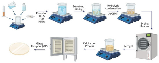
Figure 5.
Schematic illustration of the detailed steps of the synthesis route.
4.3. Characterization
For phase identification at room temperature, the XRD data were collected in 15°–80° 2θ range (step width of 0.01°, scan speed 10°/min, dwell time 5.0 s) using Ni-filtered Cu Kα1 radiation on Rigaku MiniFlexII diffractometer. The measurement current and voltage were set to 15 mA and 30 kV, respectively.
Scanning electron microscopy (SEM) micrographs were taken using Hitachi SU-70 SEM. Powder was fixed on a carbon film. The proper magnification was selected, and images were recorded. The particle size measurements were collected using open-source Fiji (ImageJ 1.52v, Java 1.8.0_112 (64-bit)) software by accidently selecting random particles.
Photoluminescence emission and excitation spectra were recorded at room temperature using a spectrometer from Edinburgh Instruments (model: FLS1000-DD-stm) equipped with a CW 450 W Xenon lamp (model: Xe2) and a cooled red photomultiplier tube (model: R928P) for detection. The spectra were corrected for the instrumental response. Photoluminescence decay kinetics were recorded using a pulsed tunable nanosecond Nd:YAG laser NT 342/3UV from Ekspla. An Andor Technologies spectrometer SR-303i-B and a time-resolved CCD camera DH734-18F-A3 were employed to record photoluminescence decay curves at room temperature.
Author Contributions
Conceptualization, M.S. and A.S.; methodology, M.S., M.L. and G.I.; software, M.S.; validation, A.S.; formal analysis, M.S. and M.K.; investigation, M.S.; resources, A.S., R.R. and R.S.; data curation, M.S.; writing—original draft preparation, M.S.; writing—review and editing, A.S.; visualization, M.S. and M.K.; supervision, A.S.; project administration, M.S. All authors have read and agreed to the published version of the manuscript.
Funding
The work of Monika Skruodiene is supported by ERDF PostDoc project No.1.1.1.2/VIAA/3/19/480. The Institute of Solid State Physics, University of Latvia has received funding from the European Union’s Horizon 2020 Framework Programme H2020-WIDESPREAD-01-2016-2017-TeamingPhase2 under grant agreement No. 739508, project CAMART2.
Institutional Review Board Statement
Not applicable.
Informed Consent Statement
Not applicable.
Data Availability Statement
The data presented in this study are available in [Synthesis and Investigation of Novel Optical Active SiO2 glasses with entrapped YAG:Ce synthesized via sol–gel method].
Conflicts of Interest
The authors declare no conflict of interest.
References
- Zarzycki, J. Past and Present of Sol-Gel Science and Technology. J. Sol-Gel Sci. Technol. 1996, 11, 17–22. [Google Scholar] [CrossRef]
- Grandi, S.; Mustarelli, P.; Agnello, S.; Cannas, M.; Cannizzo, A. Sol-Gel GeO2-Doped SiO2 Glasses for Optical Applications. J. Sol-Gel Sci. Technol. 2003, 26, 915–918. [Google Scholar] [CrossRef]
- Xia, G.; Zhou, S.; Zhang, J.; Xu, J. Structural and Optical Properties of YAG:Ce3+ Phosphors by Sol-Gel Combustion Method. J. Cryst. Growth 2005, 279, 357–362. [Google Scholar] [CrossRef]
- Inkrataite, G.; Kemere, M.; Sarakovskis, A.; Skaudzius, R. Influence of Boron on the Essential Properties for New Generation Scintillators. J. Alloy. Compd. 2021, 875, 160002. [Google Scholar] [CrossRef]
- Pan, Y.X.; Wang, W.; Liu, G.K.; Skanthakumar, S.; Rosenberg, R.A.; Guo, X.Z.; Li, K.K. Correlation between Structure Variation and Luminescence Red Shift in YAG:Ce. J. Alloy. Compd. 2009, 488, 638–642. [Google Scholar] [CrossRef]
- Najafi, A.; Sharifi, F.; Mesgari-Abbasi, S.; Khalaj, G. Influence of PH and Temperature Parameters on the Sol-Gel Synthesis Process of Meso Porous ZrC Nanopowder. Ceram. Int. 2022, 48, 26725–26731. [Google Scholar] [CrossRef]
- McGahay, V.; Tomozawa, M. Phase Separation in Rare-Earth-Doped SiO2 Glasses. J. Non-Cryst. Solids 1993, 159, 246–252. [Google Scholar] [CrossRef]
- Continenza, M.A.; Crescente, G.; Pacifico, S.; Catauro, M. Biocompatibility of New SiO2 Anti-Bacterial Material Synthesized by Sol-Gel Route. Macromol. Symp. 2021, 396, 2–4. [Google Scholar] [CrossRef]
- Pawlik, N.; Szpikowska-Sroka, B.; Goryczka, T.; Pietrasik, E.; Pisarski, W.A. Luminescence of SiO2-BaF2:Tb3+, Eu3+ Nano-Glass-Ceramics Made from Sol-Gel Method at Low Temperature. Nanomaterials 2022, 12, 259. [Google Scholar] [CrossRef]
- Fiume, E.; Migneco, C.; Verné, E.; Baino, F. Comparison between Bioactive Sol-Gel and Melt-Derived Glasses/Glass-Ceramics Based on the Multicomponent SiO2–P2O5–CaO–MgO–Na2O–K2O System. Materials 2020, 13, 540. [Google Scholar] [CrossRef]
- Feng, S.; Qin, H.; Wu, G.; Jiang, H.; Zhao, J.; Liu, Y.; Luo, Z.; Qiao, J.; Jiang, J. Spectrum Regulation of YAG:Ce Transparent Ceramics with Pr, Cr Doping for White Light Emitting Diodes Application. J. Eur. Ceram. Soc. 2017, 37, 3403–3409. [Google Scholar] [CrossRef]
- Wang, X.; Zhao, Z.; Wu, Q.; Li, Y.; Wang, Y. Synthesis, Structure and Photoluminescence Properties of Ca2 LuHf2 (AlO4)3:Ce3+, a Novel Garnet-Based Cyan Light-Emitting Phosphor. J. Mater. Chem. C 2016, 4, 11396–11403. [Google Scholar] [CrossRef]
- Almessiere, M.A.; Ahmed, N.M.; Massoudi, I.; Al-Otaibi, A.L.; Al-shehri, A.A.; Shafouri, M.A. Study of the Structural and Luminescent Properties of Ce3+ and Eu3+ Co-Doped YAG Synthesized by Solid State Reaction. Optik 2018, 158, 152–163. [Google Scholar] [CrossRef]
- Shmurak, S.Z.; Kiselev, A.P.; Kurmasheva, D.M.; Red’kin, B.S.; Sinitsyn, V.V. Effect of Solid-Phase Amorphization on the Spectral Characteristics of Europium-Doped Gadolinium Molybdate. J. Exp. Theor. Phys. 2010, 110, 759–768. [Google Scholar] [CrossRef]
- Dai, Z.; Boiko, V.; Grzeszkiewicz, K.; Markowska, M.; Ursi, F.; Hölsä, J.; Saladino, M.L.; Hreniak, D. Effect of Annealing Temperature on Persistent Luminescence of Y3Al2Ga3O12:Cr3+ Co-Doped with Ce3+ and Pr3+. Opt. Mater. 2021, 111, 110522. [Google Scholar] [CrossRef]
- Shinde, V.V.; Tiwari, A.; Dhoble, S.J. Synthesis of RE3+ (RE3+ = Ce3+, Dy3+, Eu3+ and Tb3+) Activated Gd2SiO5 Optoelectronics Materials for Lighting. J. Mol. Struct. 2020, 1217, 128397. [Google Scholar] [CrossRef]
- Xu, J.; Hassan, D.A.; Zeng, R.-J.; Peng, D.-L. Lu3 Al5O12:Ce@SiO2 Phosphor-in-Glass: Its Facile Synthesis, Reduced Thermal/Chemical Degradation and Application in High-Power White LEDs. J. Eur. Ceram. Soc. 2016, 36, 2017–2025. [Google Scholar] [CrossRef]
- Zhang, R.; Wang, B.; Zhu, W.; Li, C.; Wang, H. Preparation and Luminescent Performances of Transparent Screen-Printed Ce3+: Y3Al5O12 Phosphors-in-Glass Thick Films for Remote White LEDs. J. Alloy. Compd. 2017, 720, 340–344. [Google Scholar] [CrossRef]
- Chung, W.J.; Nam, Y.H. Review—A Review on Phosphor in Glass as a High Power LED Color Converter. ECS J. Solid State Sci. Technol. 2020, 9, 016010. [Google Scholar] [CrossRef]
- Arellano-Morales, A.; Molina-González, J.; Desirena, H.; Hernandez, J.; Calixto, S. Fast Sintering Method of Phosphor-in-Glass for High-Power LEDs. J. Lumin. 2019, 214, 116546. [Google Scholar] [CrossRef]
- Yie, H.; Kim, S.; Kim, Y.; Kim, H. Modifying Optical Properties of Phosphor-in-Glass by Varying Phosphor Size and Content. J. Non-Cryst. Solids 2017, 463, 19–24. [Google Scholar] [CrossRef]
- Maczka, M.; Bednarkiewicz, A.; Mendoza-Mendoza, E.; Fuentes, A.F.; Kȩpiński, L. Low-Temperature Synthesis, Phonon and Luminescence Properties of Eu Doped Y3Al5O12 (YAG) Nanopowders. Mater. Chem. Phys. 2014, 143, 1039–1047. [Google Scholar] [CrossRef]
- Pan, Y.; Wu, M.; Su, Q. Tailored Photoluminescence of YAG:Ce Phosphor through Various Methods. J. Phys. Chem. Solids 2004, 65, 845–850. [Google Scholar] [CrossRef]
- Pankratov, V.; Shirmane, L.; Chudoba, T.; Gluchowski, P.; Hreniak, D.; Strek, W.; Lojkowski, W. Peculiarities of Luminescent Properties of Cerium Doped YAG Transparent Nanoceramics. Radiat. Meas. 2010, 45, 392–394. [Google Scholar] [CrossRef]
- Shirmane, L.; Pankratov, V. Emerging Blue-UV Luminescence in Cerium Doped YAG Nanocrystals. Phys. Status Solidi–Rapid Res. Lett. 2016, 10, 475–479. [Google Scholar] [CrossRef]
- Inkrataite, G.; Zabiliute-Karaliune, A.; Aglinskaite, J.; Vitta, P.; Kristinaityte, K.; Marsalka, A.; Skaudzius, R. Study of YAG:Ce and Polymer Composite Properties for Application in LED Devices. Chempluschem 2020, 85, 1504–1510. [Google Scholar] [CrossRef]
- Kajihara, K. Recent Advances in Sol-Gel Synthesis of Monolithic Silica and Silica-Based Glasses. J. Asian Ceram. Soc. 2013, 1, 121–133. [Google Scholar] [CrossRef]


Disclaimer/Publisher’s Note: The statements, opinions and data contained in all publications are solely those of the individual author(s) and contributor(s) and not of MDPI and/or the editor(s). MDPI and/or the editor(s) disclaim responsibility for any injury to people or property resulting from any ideas, methods, instructions or products referred to in the content. |
© 2023 by the authors. Licensee MDPI, Basel, Switzerland. This article is an open access article distributed under the terms and conditions of the Creative Commons Attribution (CC BY) license (https://creativecommons.org/licenses/by/4.0/).