Article

Study on Micro-Displacement Mechanism and Reservoir Compatibility of Soft Dispersed Microgel

1
Research Institute of Petroleum Exploration and Development (RIPED), China National Petroleum Corporation, Beijing 100083, China
2
Key Laboratory of Nano Chemistry (KLNC), China National Petroleum Corporation, Beijing 100083, China
3
Exploration and Development Research Institute of Southwest Oil and Gas Field Company, China National Petroleum Corporation, Chengdu 610041, China
4
No. 1 Oil Production Plant of North China Oil and Gas Company, SINOPEC, Xianyang 712034, China
*
Authors to whom correspondence should be addressed.
Gels 2023, 9(3), 177; https://doi.org/10.3390/gels9030177
Submission received: 5 February 2023 / Revised: 15 February 2023 / Accepted: 20 February 2023 / Published: 23 February 2023

Abstract

:
Polymer flooding is a key technology for improving reservoir heterogeneity around the world, and it has made great progress. However, the traditional polymer has many shortcomings in the theory and application, which causes the efficiency of polymer flooding to gradually decrease and secondary reservoir damage after a long period of polymer flooding. In this work, a novel polymer particle (soft dispersed microgel, SMG) is used as the research object to further investigate the displacement mechanism and reservoir compatibility of SMG. The visualization experiments of the micro-model prove that SMG has excellent flexibility and can be highly deformable to realize deep migration through the pore throat smaller than SMG itself. The visualization displacement experiments of the plane model further show that SMG has a plugging effect, which makes the displacing fluid flow into the middle and low permeability layers, improving the recovery of these layers. The compatibility tests show that the optimal permeability of the reservoir for SMG-μm is 250–2000 mD, and the corresponding matching coefficient range is 0.65–1.40. For SMG-mm, its corresponding optimal permeabilities of reservoir and matching coefficient are 500–2500 mD and 1.17–2.07, respectively. The comprehensive analysis demonstrates that the SMG has excellent ability of the water-flooding swept control and compatibility with reservoirs, having the potential to solve the problem of traditional polymer flooding.

1. Introduction

The types of oilfields in China are complex and diverse, most of which are continental sedimentary and characterized by severe heterogeneity [1,2,3,4]. The number of oil reservoirs developed by water flooding accounts for more than 92% of the total reservoirs in China. The majority of oilfields of China National Petroleum Corporation (CNPC) have entered the period of high water-cut and extra high water-cut except for Changqing. The remaining recoverable reserves of these high water-cut and extra high water fields account for more than 60%, and their production accounts for more than 70% of the total production. Therefore, improving the effect of water-flooding development is of great significance to the strategic goal and national security of stable production of 100 million tons of CNPC.
Polymer flooding is the main method for ineffective or inefficient water flooding in high water-cut and extra high water-cut oilfields [5,6,7,8,9]. Polymer is developed from inorganic profile control agents such as clay, fly ash, and cement to organic gel profile control agents in the 1970s. Although polymer flooding has made great progress [10,11,12,13,14,15,16,17,18], due to its small injection volume and small treatment radius, it can only play a certain role in the longitudinal heterogeneity near-well zone, and it is only a production measure, strictly speaking. In order to solve the limitation that polymer flooding can only be used in the near-well area. Many scholars try to conduct “high-dose profile control”, also known as “deep profile control” [19,20,21,22,23], but the treatment radius is often no more than 10–20 m and the treatment cost is high. In addition, with the increase of water-cut in oilfields, the water-flooding contradiction changes from the shallow reservoir to the deep reservoir, or even the entire reservoir flow field. The traditional polymer flooding, including profile control and water shut-off technology, can only achieve the purpose of increasing the production of a single well and cannot fundamentally solve the problem of improving recovery in a high water-cut period.
In order to solve these problems, SMG-based water-flooding swept control technology is established by Professor Wu Xingcai, Research Institute of Petroleum Exploration, and Development of CNPC [24]. This technique can effectively sweep the whole flow field through a process of temporary plugging-passing-turning-plugging-passing of a large number of SMG in the whole reservoir [25,26,27]. This technology has been used in many reservoirs with different temperatures (28–126 °C), different viscosities (4–165 mPa·s), different salinities (2000–20 × 104 mg/L), different water-cuts (80–98%), and different production degrees (14–48%) in North China, Xinjiang, Liaohe, Qinghai, Dagang, and so on, and it has achieved obvious results [28,29,30,31,32,33]. However, the oil displacement mechanism of SMG is not clear enough, and the exact matching between SMG and reservoirs is lacking.
In this work, the oil displacement mechanism of SMG is further studied, and the effectiveness of SMG-based water-flooding swept control technology is confirmed by the visualization experiments. Besides, the matching relationship between SMG and reservoirs has been determined by the displacement experiments of cores. The comprehensive analysis demonstrates that the SMG has excellent ability of water-flooding swept control and compatibility with reservoirs, having the potential to solve the problem of the traditional polymer flooding.

2. Results and Discussions

2.1. Swelling Property of SMG

The swelling multiple is a representation of the SMG with hydration swelling property. The initial median particle size of SMG is d0, which reflects the median particle size before hydration swelling. After 7 days of SMG hydration swelling, the measured median particle size of SMG is dmax. The test results show that the expansion multiple (B) of SMG particles is about 3–8 times, and the expansion multiple of SMG-μm is larger than that of SMG-mm, as shown in Table 1. The concentration of SMG aqueous dispersion is 3000 mg/L. The experimental temperature is 60 °C.
In general, the polymer solution, the melt fluid of the discrete system of colloidal particles, are all non-Newtonian fluids. The swelling rate of SMG hydration belongs to the kinetic problem of water absorption of polymer materials. Superabsorbent gels belong to elastic gels, and they follow the general law of elastic gels expansion kinetics.
δ u δ t = D δ 2 u δ 2 r
D = k / f r
where δ u δ t is the diffusion velocity of the gel unit. δ 2 u δ 2 r is the second derivative of the change in the radius of the diffusion element. The diffusion coefficient D is the elasticity of the mesh. K is the ratio of the mesh to the viscosity coefficient fr of the solvent.
Equation (1) is derived by Japanese researchers based on Flory’s theory according to Fickian diffusion’s second law.
Equation (2) is the diffusion equation. By solving this equation, Equation (3) can be obtained, which can explain the relationship between characteristic swelling time t and characteristic linear size L.
t L 2 D
This is the kinetic equation for the volume expansion of the gel in the solvent. From this equation, it can be seen that the smaller the particle size of the gel, the faster the swelling. It should be noted that due to the different shapes and ionization states of gels, they should be adjusted in practical applications. This mechanism also further explains why the expansion times of hydration measured by SMG-μm are greater than that measured by SMG-mm.
The observation results of SMG morphology show that SMG particles are spherical with good sphericity, as shown in Figure 1. Then, for the same sample, the size of SMG particles after purification dyeing are not different from those without dyeing, as shown in Figure 1.

2.2. Rheological Property of SMG Aqueous Dispersion

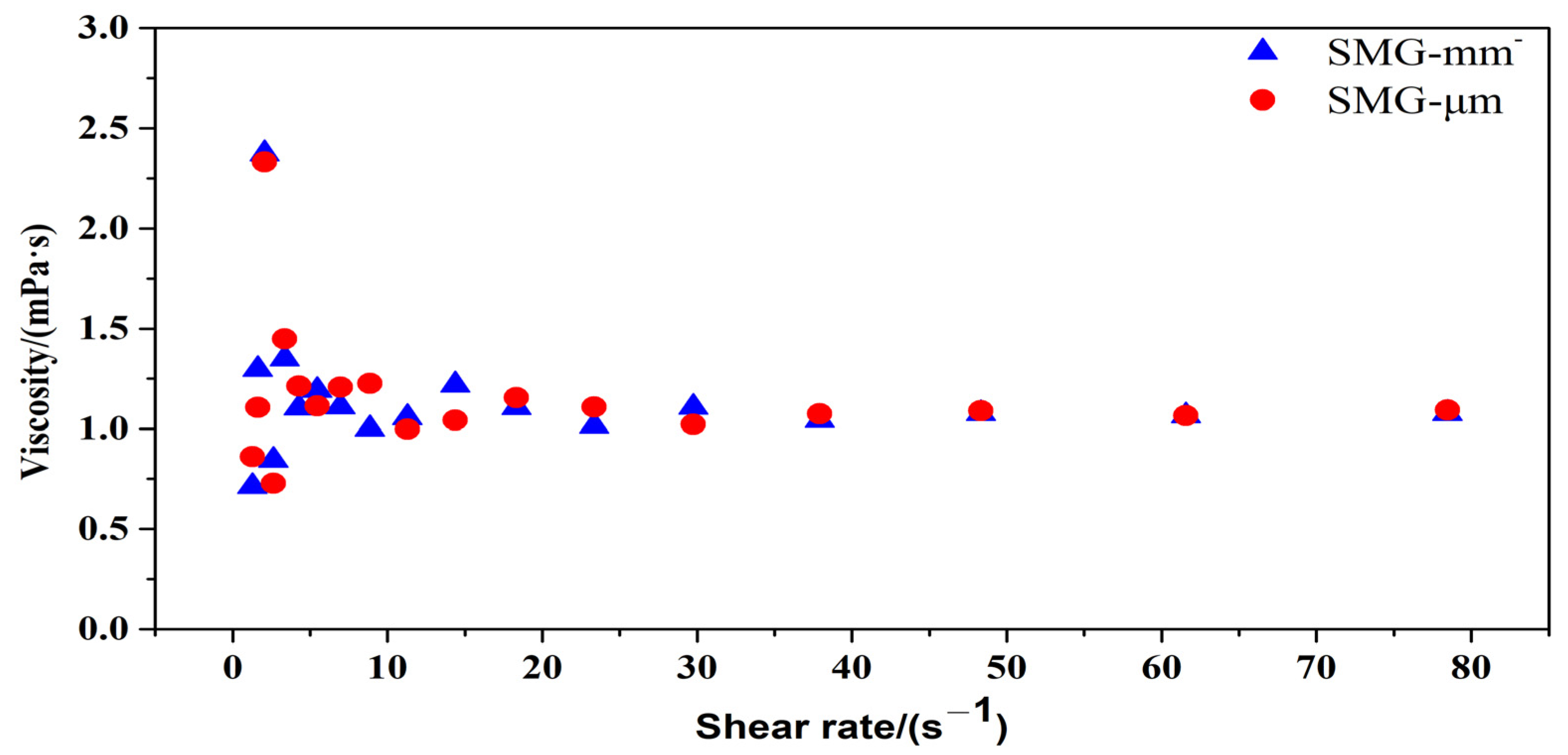
The rheological property of SMG aqueous dispersion with a concentration of 3000 mg/L is tested. The relationship between the apparent viscosity of SMG aqueous dispersion and shear rate is shown in Figure 2. The apparent viscosity fluctuates when the shear rate is 1–10 s−1. When the shear rate is 10–80 s−1, the apparent viscosity is unstable and slightly decreased, showing a weak pseudoplastic character.
Figure 3 shows the mechanism of shear thinning of non-Newtonian fluid, including matchstick particles, chain molecules, flexible particle dispersion such as SMG aqueous dispersion system, and molecular line group. Theoretically, flexible particle dispersion is characterized by shear thinning. The reason is that the flexible particle dispersion is composed of multiple components. At rest, all these substances will maintain an internal irregularity and thus have a fairly high internal resistance, that is, a high viscosity, which in turn hinders movement, as shown in Figure 3a. As the shear rate increases, spherical particles or molecular lines suspended in the liquid can more easily slip past each other, turning the spherical particles into rugby bodies, or ellipsoids with smaller diameters, allowing the samples to flow faster, as shown in Figure 3b. SMG aqueous dispersion of low concentration has low viscosity, and the value is close to water, as shown in Figure 4.

2.3. Micro-Scale Experiment of SMG

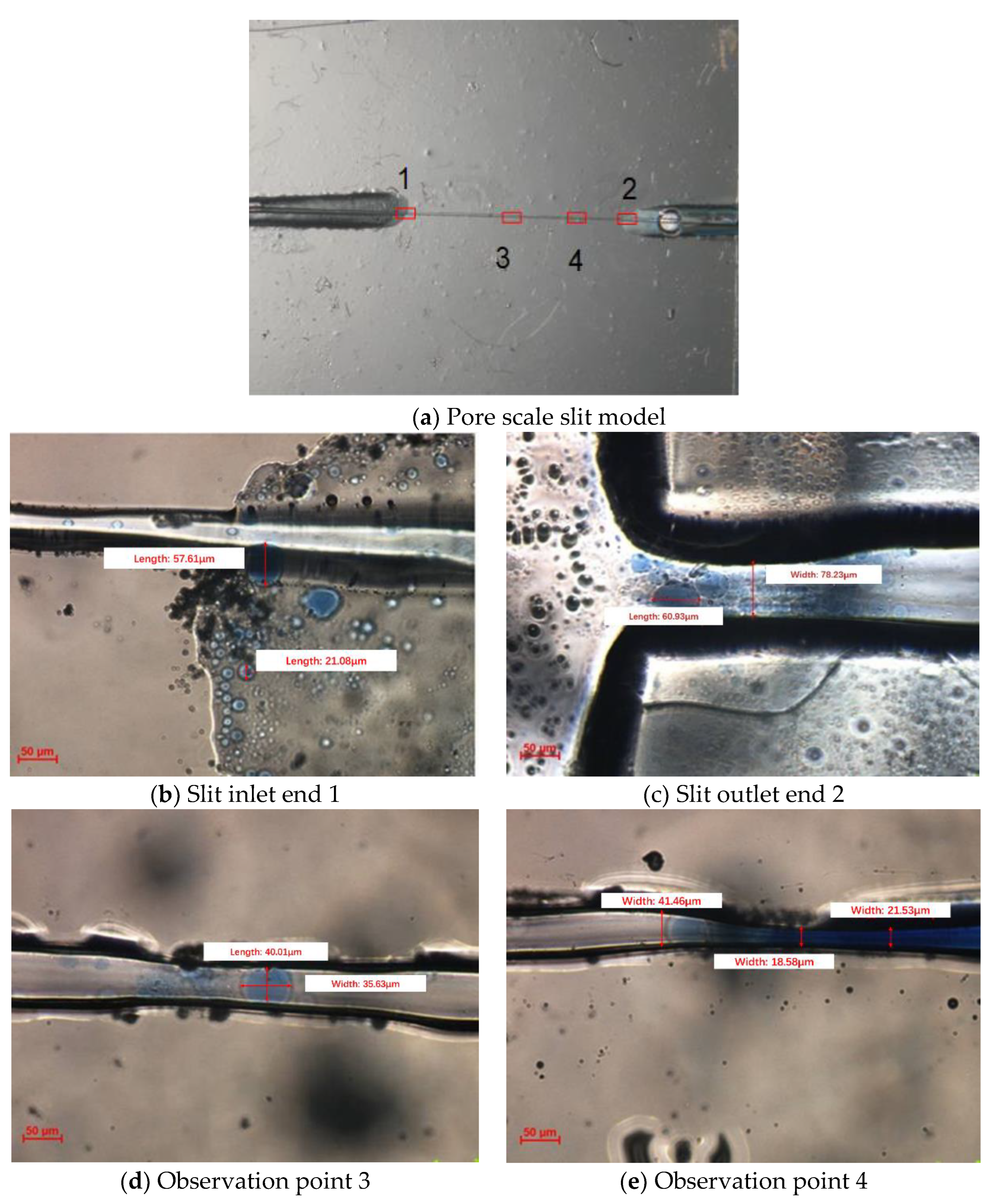
Figure 4 shows the micro-scale physical simulation experiment photos of the pore scale slit model. The pore scale slit model contains four observation points, namely, the inlet end 1, the outlet end 2, and the observation points 3 and 4, as shown in Figure 4a. Observation point 3 is a capillary channel, and observation point 4 is an expanding-shrinking-expanding channel. Because SMG particles flow too quickly through the pores in the injecting process of SMG aqueous dispersion, there is no way to capture images of rapid SMG particle migration directly using a biological microscope. With the injection pump turning off, the velocity of SMG particles decreases. The remaining SMG particles at the inlet end continue to migrate in the microscopic model under the action of inertial forces, which can be recorded by a biological microscope. The flow process of SMG aqueous dispersion is observed with a biological microscope, as shown in Figure 4b–e. Through observation of points 3 and 4, the deformation of SMG particles and the process of temporary plug throat can be clearly observed. In addition, SMG particles observed at outlet 4 show no crushing phenomenon, indicating that SMG particles had good elastic deformation and shear resistance.
Figure 5 shows the SMG profile control and oil displacement experiment process of the anti-rhythm sand inclusion model. The model is composed of three layers, from top to bottom, the high permeability layer, the middle permeability layer, and the low permeability layer. Figure 5a shows the model after saturated oil. Figure 5b shows the distribution of residual oil when the water-cut at the outlet reaches 95%. In the process of water flooding, the majority of injected water flows into the high permeability layer above, and most of the oil in the high permeability layer and middle permeability layer is displaced. In contrast, the fraction of water flows into a low permeable zone and the lower part of the medium permeability zone, and only a small amount of oil is displaced. Figure 5c shows the initial state of the model at the beginning of SMG flooding. It can be seen from this photo that the seepage direction of SMG is along the main flow line, and part of it flows into the high permeability reservoir. In addition, as can be seen from Figure 5d, most SMG flows into the upper part of the high permeability layer, some enter into the middle permeability layer, and only a small amount enters into the low permeability layer.
Figure 5e,f shows the state of SMG aqueous dispersion just breaking through the high permeability layer. After breaking through the high permeability layer, the SMG aqueous dispersion migrates along the middle and low permeability layers. Figure 5g–i shows the experimental process of SMG improving the contradictions in the layer and starting the middle and low permeability permeable layer.
It can be seen from the residual oil saturation in the model that the oil displaced by SMG flooding is mainly from the middle and low permeability layers. This is because the SMG particle has a certain blocking ability, which makes the water turn to the middle and low permeability layer, which can improve the recovery of the middle and low permeability layer.

2.4. Analysis of Experimental Results of the Matching Relationship between SMG Particles and Reservoirs

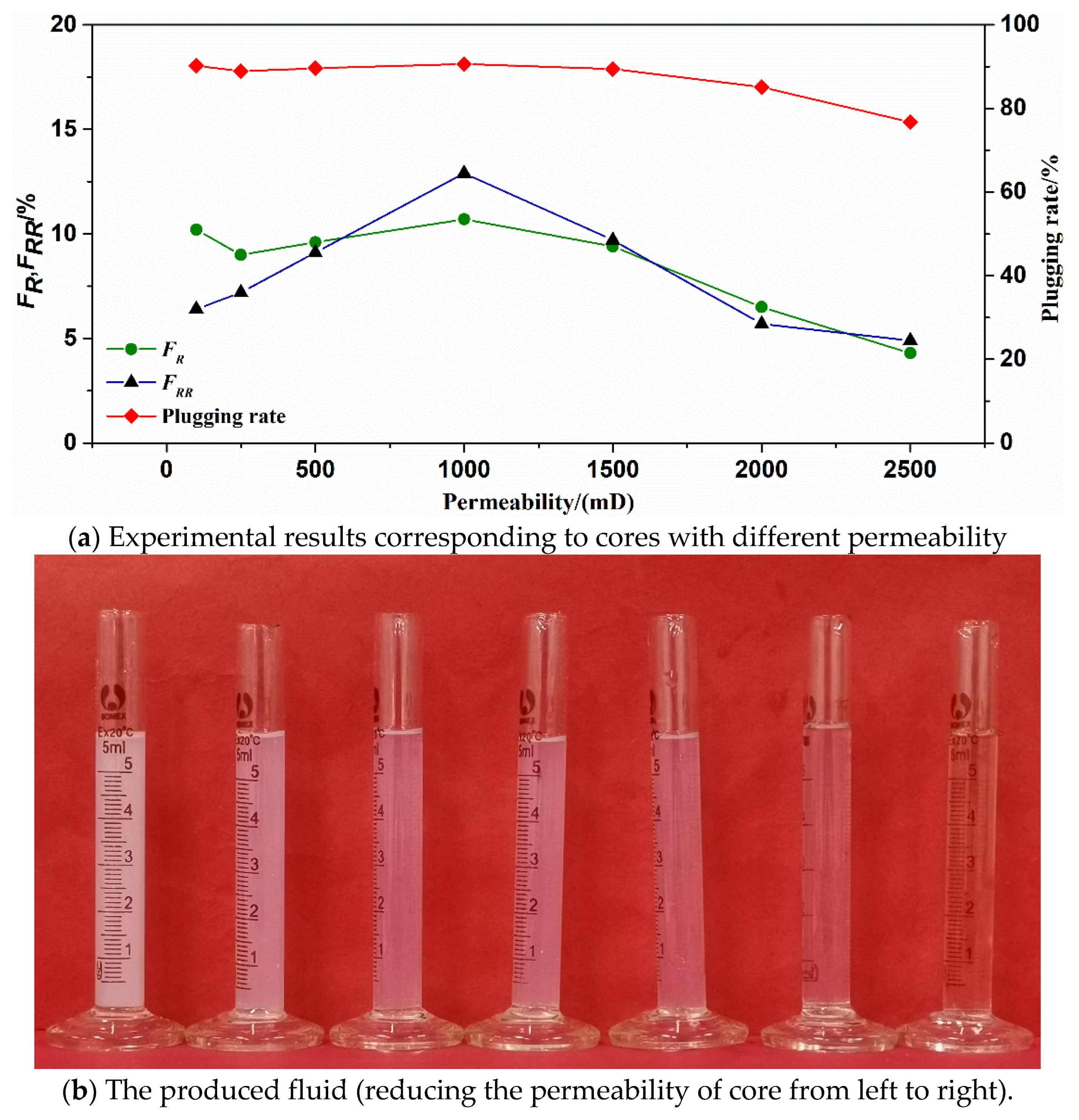
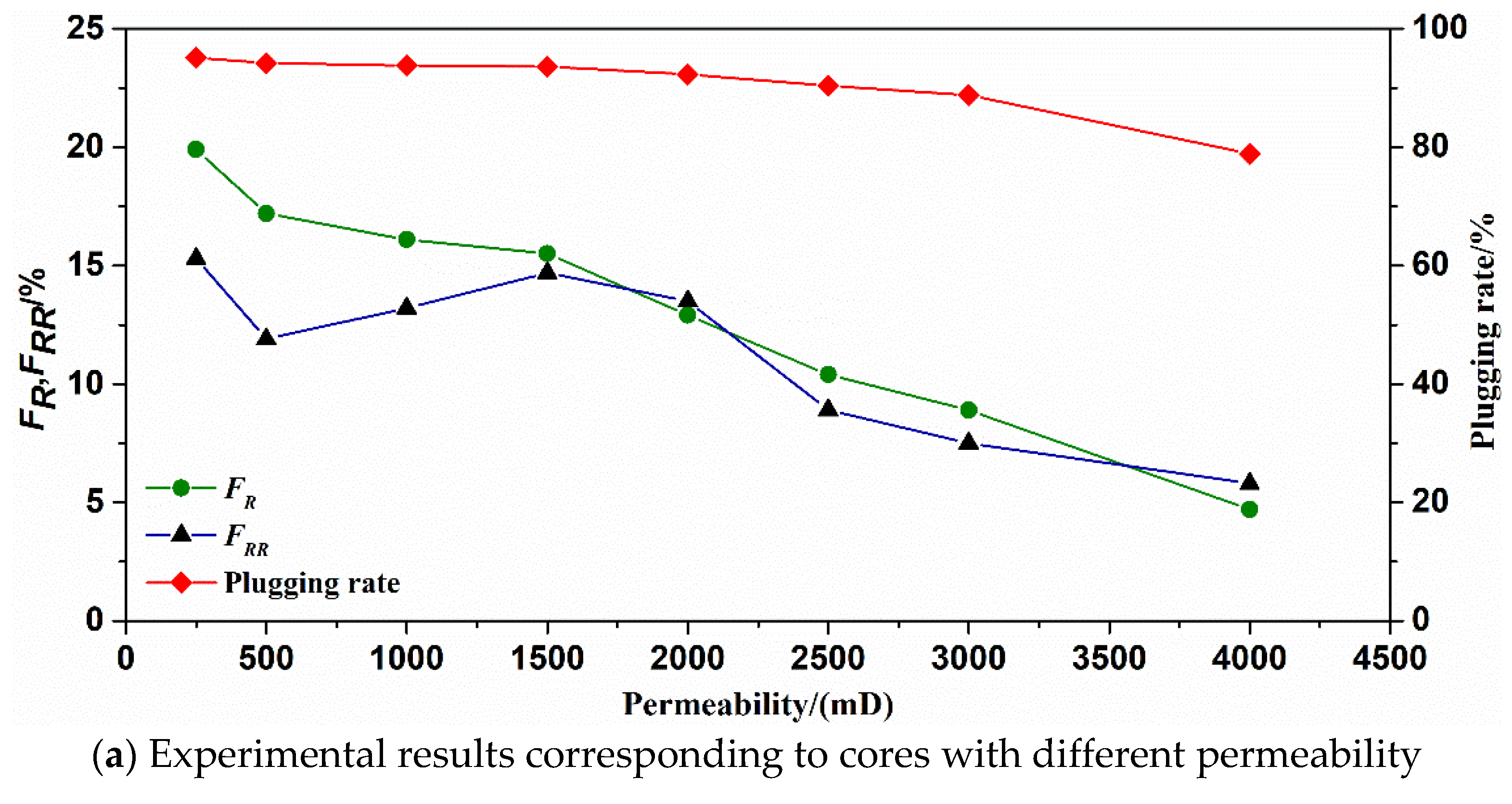
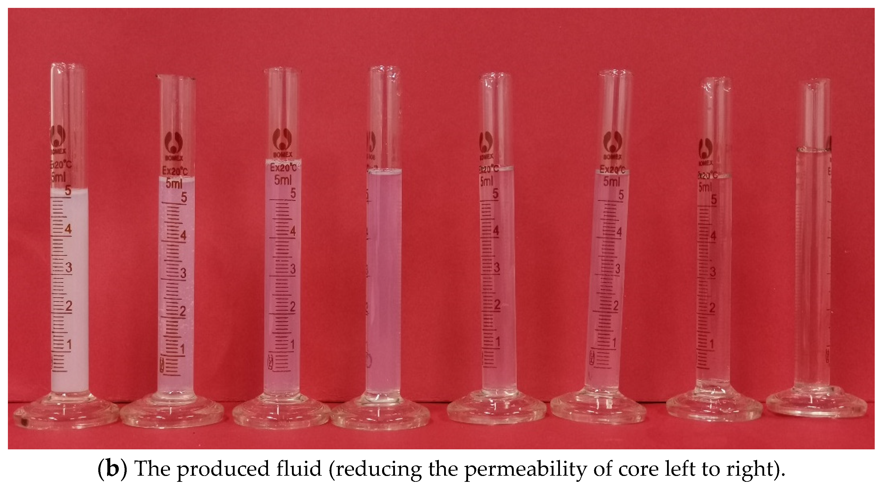
The matching relationship, SMG particles and reservoirs can be determined by the displacement experiments of cores. The results are shown in Table 2 and Table 3, respectively. It can be observed from Figure 6a and Figure 7a that the matching coefficient of SMG-μm and SMG-mm decreases with the increase of core permeability. When the core permeability increases from 100 to 2500 mD, the matching coefficient of SMG-μm decreases from 1.69 to 0.55. When the core permeability increases from 250 to 3000 mD, the corresponding matching coefficient of SMG-mm decreases from 2.67 to 0.88. As shown in Figure 6b and Figure 7b, with the continuous increase of the matching coefficient, the color of the produced liquid during the injection of the SMG-μm and SMG-mm gradually becomes lighter, which preliminarily indicates that the SMG concentration in the produced liquid increased with the increasing of core permeability. At the same time, the corresponding resistance factor (FR) in the displacement experiments of the core decreased with the increase of core permeability. The residual resistance factor (FRR) first increases and then decreases as the core permeability increases, and the plugging rate increases with the core permeability.
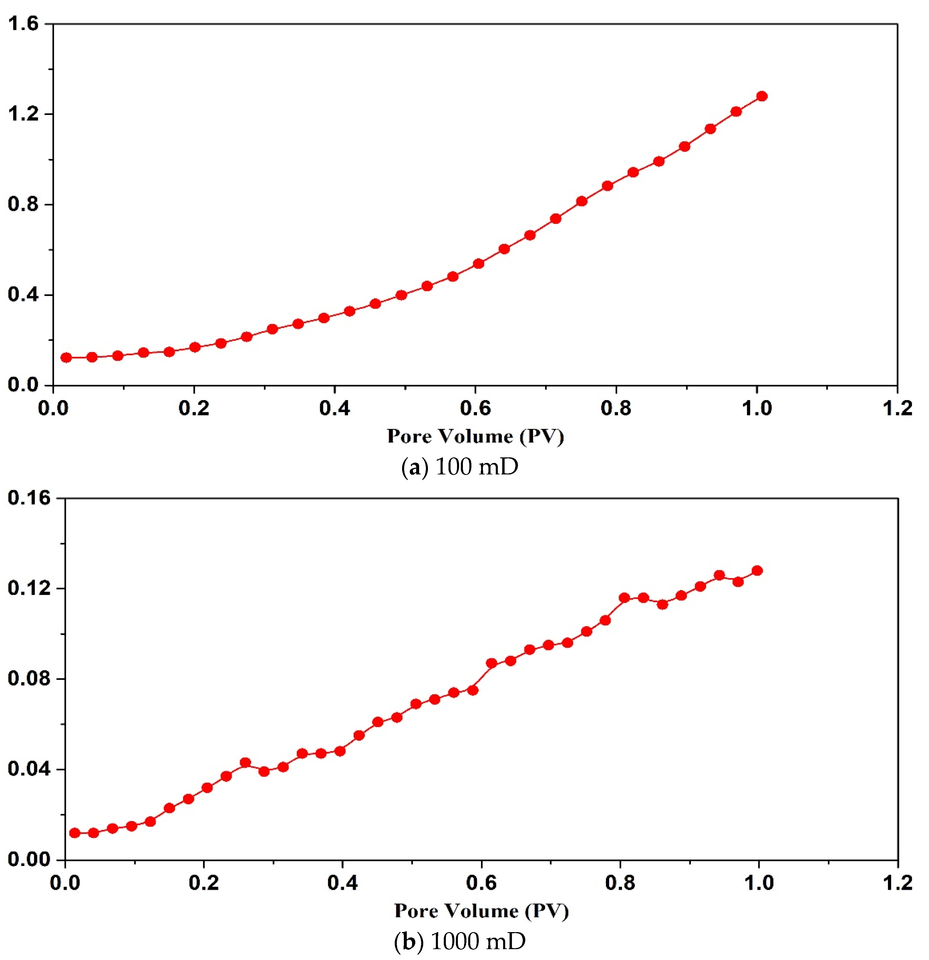
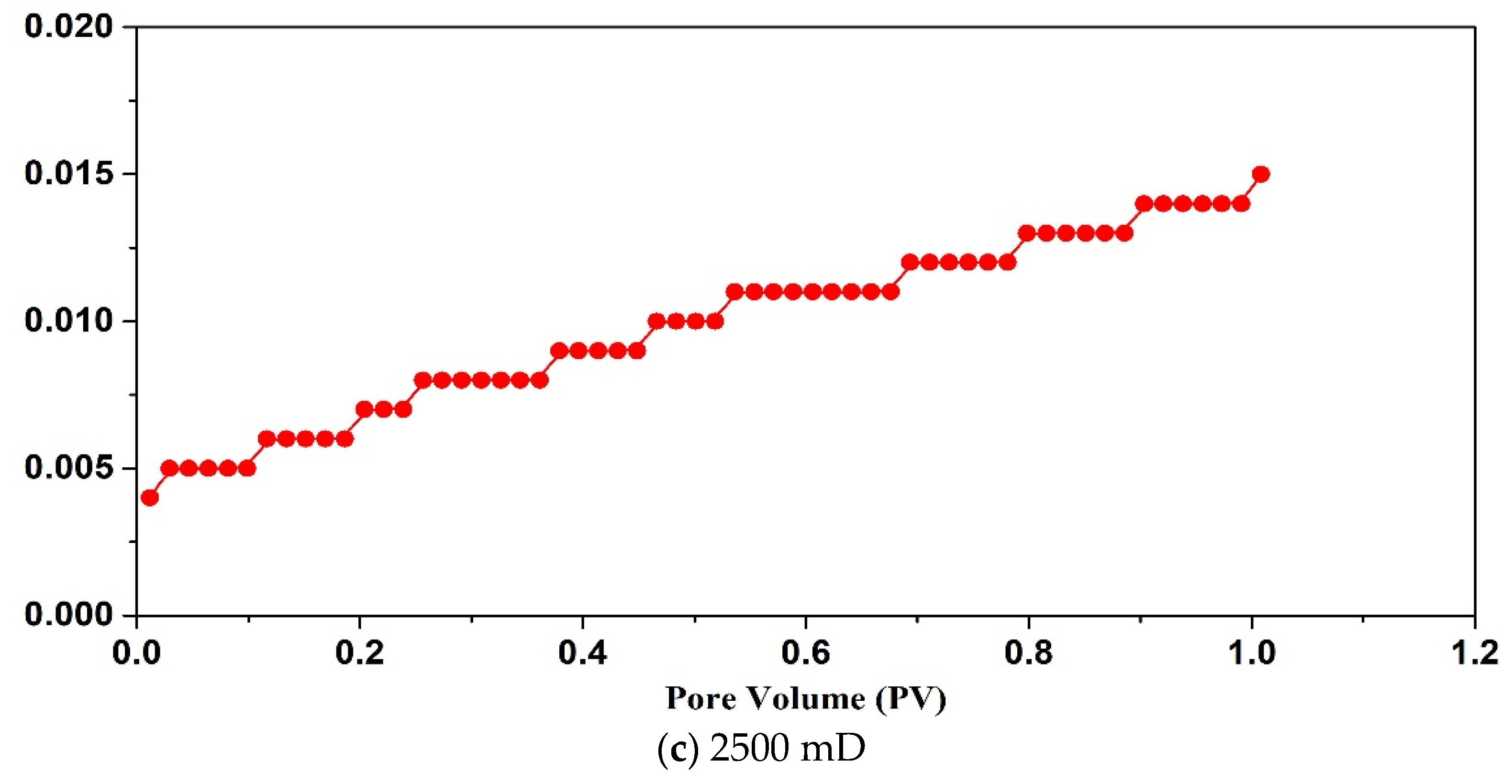
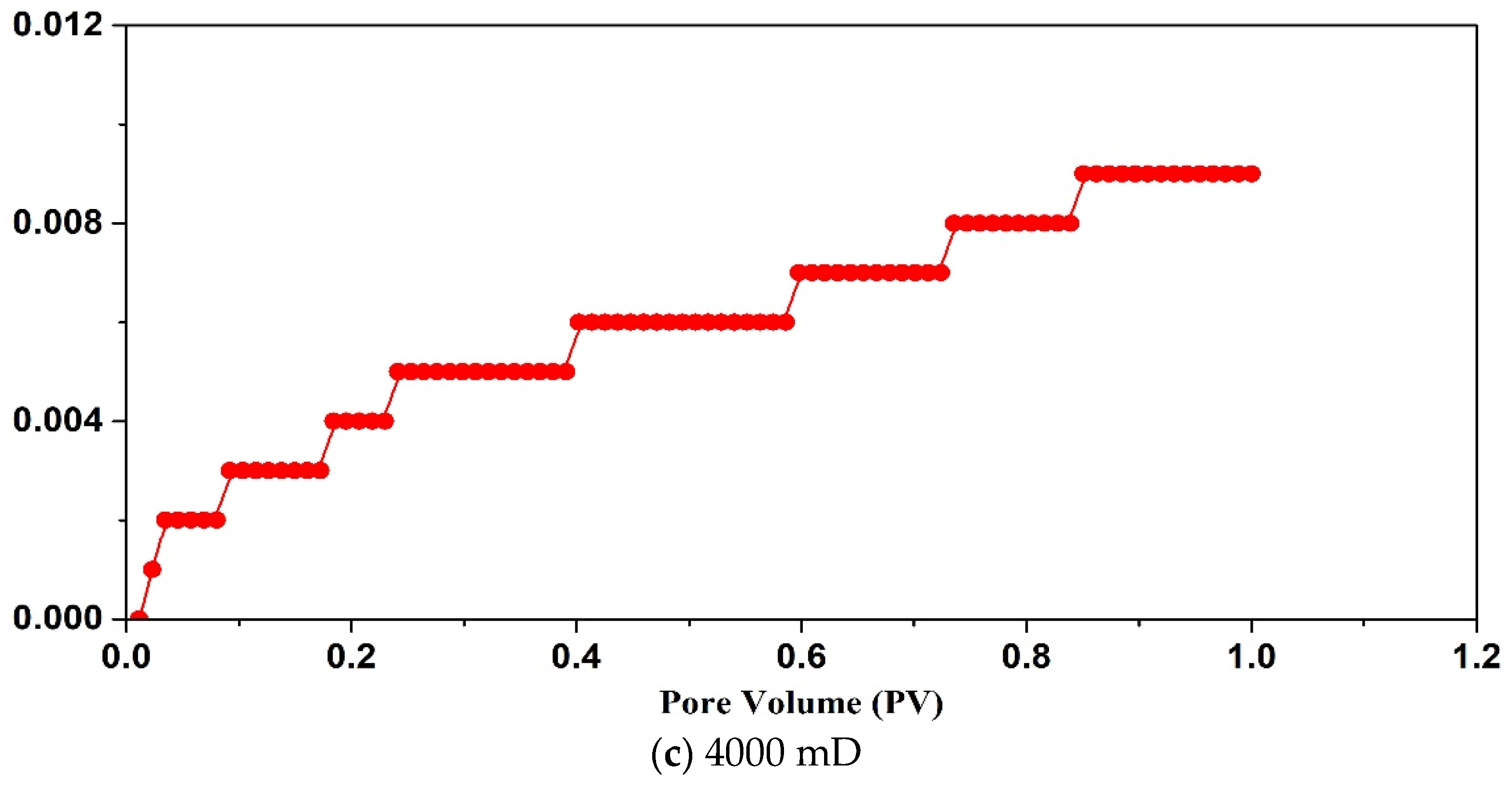
By analyzing Figure 8 and Figure 9, it can be seen that when the permeability of the core is less than 100 mD, the SMG-μm particle can’t effectively enter the core and accumulates at the injection end of the core, showing that the injection pressure is an exponential function. When the core permeability is 1000 mD, SMG-μm particle effectively enters the core and migrates into the core, showing a wave-like rise in pressure. When the permeability is 2500 mD, and only if there is enough SMG-μm particle in the throat, the pore throat can be effectively sealed, which is manifested as a slow rise in pressure in a stepwise manner. Similarly, the variation tendency of the injection pressure curve of SMG-mm particles in the three cores with different permeability of high, medium, and low is basically the same as that of the SMG-μm particle.
Based on the above experimental analysis, the matching results of the relationship between SMG particles and reservoirs can determine that the SMG-μm is best adapted to reservoirs with a permeability of 250–2000 mD, and the corresponding matching coefficient is 0.65–1.40. The SMG-mm is best adapted to reservoirs with a permeability of 500–2500 mD, and the corresponding matching coefficient is 1.17–2.07.

3. Conclusions

SMG has low viscosity and high shear resistance, which makes it easy to migrate deeper into the reservoirs and provides better water-flooding swept control performance.
The microscopic oil displacement mechanism for SMG has been further proved by the visual sand inclusion model. The behavior of “temporary plugging-migration-temporary re-plugging” in the pores is observed, which can expand the water-flooding sweep volume and improve the reservoir’s ultimate oil recovery.
The exact matching relationship between the SMG particle and the reservoir has been determined. SMG-μm is more suitable for reservoirs with 250–2000 mD, and SMG-mm is more suitable for reservoirs with 500–2500 mD.

4. Materials and Methods

4.1. Preparation of Materials

Two glass models are developed: pore scale slit model and visual sand inclusion model. (1) The “∞” shape model produced by the traditional microscopic model making process has a throat of 100–200 μm and a depth of about 20 μm, which has the problem of “too large width to depth ratio”, as shown in Figure 10a. In order to prevent SMG from getting stuck in the model, the pore scale slit model is designed and made independently by using glass material. The depth and width of the slit are 90 μm and 10–50 μm, respectively, as shown in Figure 10b. (2) The visual inclusion sand model is formed by filling quartz sand glue between two flat glasses. The model is divided into three layers according to the formation prosodic. From top to bottom, the first layer is filled with 40–60 mesh sand (high permeability layer), the second layer with 80–120 mesh sand (medium permeability layer), and the third layer with 160–180 mesh sand (low permeability layer). The thickness of the sand layer is about 1.3–1.4 mm. The permeability of the three layers is 3000, 1500, and 900 mD, respectively, and the experimental model size is about 13 × 9 × 0.1 cm3, as shown in Figure 10c.
The parameters of the artificial core used in experiments are shown in Table 4.
The reagent of micro-SMG (SMG-μm) and submillimeter SMG (SMG-mm) is provided by the Research Institute of Petroleum Exploration and Development of CNPC. In order to exclude the influence of impurity and observe the SMG particle morphology better, the SMG solution is added into a beaker of alcohol with a concentration of 99.7% while stirring with a glass rod to force SMG into full contact with the alcohol. Then, the separable solid of SMG is extracted by repeatedly filtering and washing. Then the extracted separable solid of SMG is placed in an oven at 60 °C for 5 h to obtain SMG dry powder. SMG aqueous dispersion is prepared with SMG dry power and simulated brine. The viscosity of simulated oil is 12 mPa·s. Simulated brine is prepared according to Table 5.

4.2. Experimental Setups

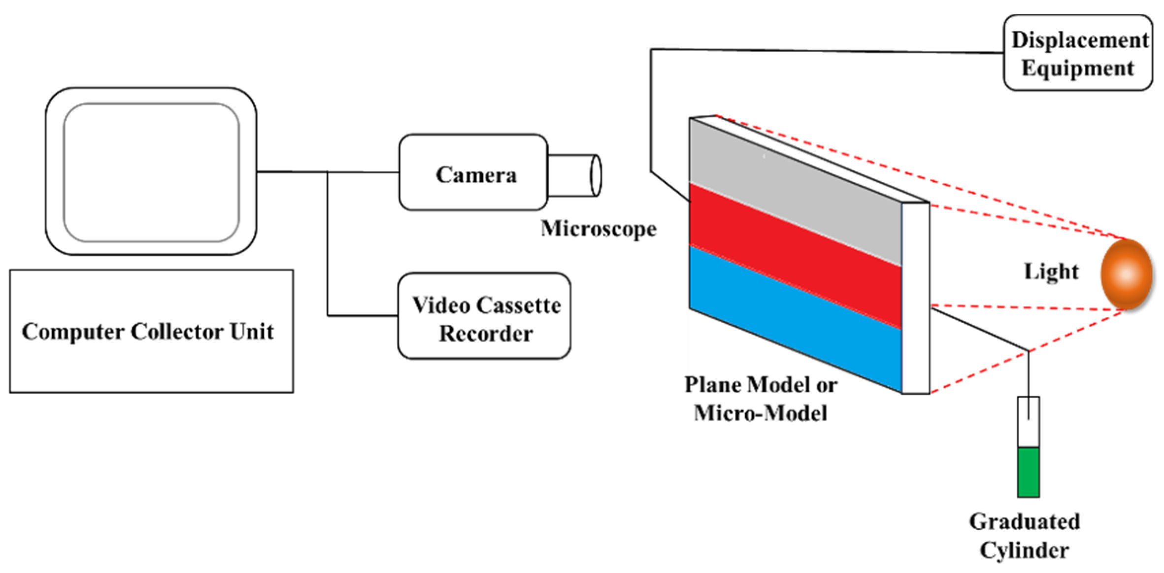
The HAAK-RS-600 rheometer with double-gap rotary cylinder sensing system comes from HAAKE Company, Karlsruhe, Germany. The visual displacement equipment of the model includes a stereo microscope, Biooptical Microscope (Nikon 80i), camera, video cassette recorder (VCR), displacement equipment, core holder, intermediate container, pressure sensor, and so on, as shown in Figure 11.

4.3. Methods

4.3.1. Measurement of SMG Particle Size and Rheological Property

The dynamic light scattering method (DLS) is used to measure the size of SMG particles. The SMG is stained with methylene blue, and the morphology of SMG is observed by microscope. The concentration of SMG aqueous dispersion is 3000 mg/L. The experimental temperature is 25 °C
The surface viscosity of SMG aqueous dispersion is measured when the shear rate increased from 1 s−1 to 80 s−1. The test temperature and SMG aqueous dispersion concentration are 25 °C and 3000 mg/L, respectively.

4.3.2. Microinjection Experiment

The visual sand inclusion model is weighed (W1) after placing it in a 60 °C oven for 12 h. Subsequently, this model is weighed (W2) again after being evacuated and saturated simulated brine. The saturated brine volume can be calculated by V = W2 − W1, which can reflect the pore volume of the sand inclusion model. Besides, the original oil saturation of the model is established by injecting simulated oil into this model. Water-flooding of the visual sand inclusion model is performed after 48 h of oil saturation. The displacement velocity is 0.3 mL/min, and the changes of oil and water production at different times are recorded. When the water-cut of the produced liquid reaches about 95%, water-flooding is stopped, and SMG aqueous dispersion is injected. The injection volume is 0.3 times the pore volume (PV) of the model. It is emphasized that the concentration of SMG aqueous dispersion is 3000 mg/L. The experimental temperature is 25 °C.

4.3.3. Experiment on the Matching Relationship between SMG Particle and Reservoir

The artificial cores are successively dried, vacuumed, saturated with simulated brine, and permeability measured. Subsequently, the matching experiments between SMG particles and the reservoir is conducted. The concentration of SMG aqueous dispersion is 3000 mg/L. The specific operation steps are as follows: (1) Primary water-flooding, brine is injected into the artificial core until the pressure is stable; (2) SMG-flooding, 1 time the pore volume of the SMG aqueous solution is injected into the core; (3) Subsequent water-flooding, the experiment is terminated when the injection pressure shows no change for 20 min. It is emphasized that the injection rate of the whole experiment is 1 mL/min. The pressures at end of primary water flooding, SMG-flooding, and subsequent water flooding are P1, P2, and P3, respectively. The resistance factor (FR) and residual resistance factor (FRR) can be calculated with Equations (4) and (5). The confining pressure of the core holder is always greater than the injection pressure by about 3 MPa. The concentration of SMG aqueous dispersion is 3000 mg/L. The experimental temperature is 25 °C.
F R = P 2 P 1
F R R = P 3 P 1
The ratio of the SMG median particle diameter to the average pore throat diameter of the reservoir or core is defined as the matching coefficient Z, as shown in Equation (6), where the average pore throat diameter of the reservoir is based on the Cozeny-Kalman formula [34], as shown in Equation (7). By combining Equations (6) and (7), Equation (8) can be obtained.
Z = d S M G d t h r o a t
K = φ d t h r o a t 2 16 f c k τ 2
Z = φ d S M G 2 / ( 72 K )
where d S M G is SMG median particle diameter, μm; d t h r o a t is the average pore throat diameter of the reservoir or core, μm; φ is porosity of reservoir or core, %. K is permeability. f c k τ 2 is the constant, which is related to the complexity of the pore throat structure. In this paper, the value of f c k τ 2 is 4.5.

Author Contributions

Methodology, Y.Y., Y.L., Z.Y., X.W. and S.L.; software, Y.L. and P.X.; formal analysis, Y.Y., B.G. and L.H.; investigation, Y.Y., Y.L. and Z.Y.; re-sources, L.H. and P.X.; data curation, Y.Y., Y.L. and Z.Y.; writing—original draft preparation, Y.Y., Y.L. and Z.Y.; writing—review and editing, Y.L.; project administration, Y.Y. All authors have read and agreed to the published version of the manuscript.

Funding

This research was funded by Science and Technology Management Department of China National Petroleum Corporation, Research on Optimal Profile Control and Oil Displacement Technology of Fine Water-flooding in Low Permeability Reservoir (No. 2021DJ1303).

Institutional Review Board Statement

Not applicable.

Informed Consent Statement

Not applicable.

Data Availability Statement

The data supporting the findings of this manuscript are available from the corresponding authors upon reasonable request.

Acknowledgments

The authors of the paper would like to thank the Research Institute of Petroleum Exploration & Development, China National Petroleum Corporation, for the permission to publish the paper, and also to acknowledge the financial support of the project from the Science and Technology Management Department of China National Petroleum Corporation, Research on Optimal Profile Control and Oil Displacement Technology of Fine Water-flooding in Low Permeability Reservoir (No. 2021DJ1303).

Conflicts of Interest

The authors declare no conflict of interest.

References

  1. He, L.; Hanbing, X. Deep Fluid Diversion for Profile Control and Oil Displacement Technologies. In Proceedings of the International Petroleum Technology Conference, Bangkok, Thailand, 15–17 November 2011; p. 14217. [Google Scholar]
  2. Xiangguo, L.; Bao, C.; Kun, X.; Weijia, C.; Yigang, L.; Yunbao, Z.; Xiaoyan, W.; Jie, Z. EOR mechanisms of polymer flooding in a heterogeneous oil reservoir. Pet. Explor. Dev. 2021, 48, 148–155. [Google Scholar]
  3. Cancan, Z.; Yongjun, W.; Fengming, Z. Modeling and application of the lithofacies controlled primary pore reservoir of proximal sandstone. Pet. Explor. Dev. 2006, 33, 553–557. [Google Scholar]
  4. Qitai, Q. Three major rich areas of “large scale” unswept remaining oil in water flooded beded sandstone resrvoirs. Acta Pet. Sin. 2000, 21, 45–50. [Google Scholar]
  5. Yang, S.; Yunfei, X.; Zhihua, W. An Experimental Study on Efficient Demulsification for Produced Emulsion in Alkaline/Surfactant/Polymer Flooding. J. Energy Resour. Technol.-Trans. Asme 2022, 144, 093001. [Google Scholar] [CrossRef]
  6. Juarez-Morejon, J.L.; Bertin, H.; Omari, A.; Hamon, G.; Cottin, C.; Morel, D.; Romero, C.; Bourdarot, G. A New Approach to Polymer Flooding: Effects of Early Polymer Injection and Wettability on Final Oil Recovery. SPE J. 2019, 24, 129–139. [Google Scholar] [CrossRef] [Green Version]
  7. Delamaide, E. Polymer Flooding of Heavy Oil-Form Screening to Full-Field Extension. In Proceedings of the SPE Heavy and Extra Heavy Oil Conference: Latin America, Medellín, Colombia, 24–26 September 2014; p. 171105. [Google Scholar]
  8. Afeez, G.; Shirish, P.; Shahzad, K.M.; Adewunmi, A.A.; Yusuff, A.S.; Agi, A.; Oseh, J. Application of Polymers for Chemical Enhanced Oil Recovery: A Review. Polymers 2022, 14, 1433. [Google Scholar] [CrossRef]
  9. Darbi, A.M.; Ling, P.A.; Agus, A.; Junin, R.; Syariefudin, M.I.; Regina, S.; Husna, U.Z.; Ahmadipour, M. A Short Review of Biopolymers for Enhanced of Oil Recovery in Mature Fields. Pet. Chem. 2022, 62, 482–498. [Google Scholar] [CrossRef]
  10. Chenzhi, Y. Chemical Flooding to Enhance Oil Recovery; Petroleum Industry Press: Beijing, China, 1999; pp. 40–56. [Google Scholar]
  11. Masalmeh, S.K.; Wei, L.; Blom, C.; Jing, X.D. EOR Options for Heterogeneous Carbonate Reservoirs Currently Under Waterflooding. In Proceedings of the Abu Dhabi International Petroleum Exhibition and Conference, Abu Dhabi, United Arab Emirates, 10–13 November 2014; p. 171900. [Google Scholar]
  12. Shuyun, W.; Yanming, B.; Jie, S.; Zhaohui, Y. Polymer-injection response of tertiary infilling producers in the west-central area, Daqing Oilfield. Pet. Explor. Dev. 2004, 31, 123–125. [Google Scholar]
  13. Dongmei, W.; Huanzhong, D.; Changsen, L.; Fu, X.; Nie, J. Review of Practical Experience of Polymer Flooding at Daqing. SPE Reserv. Eval. Eng. 2009, 12, 114342. [Google Scholar]
  14. Prasad, D.; Pandey, A.; Kumar, M.S.; Koduru, N. Pilot to Full-field Polymer Application in One of the Largest Onshore Field in India. In Proceedings of the SPE Improved Oil Recovery Symposium, Tulsa, OK, USA, 12–16 April 2014; p. SPE-169146-MS. [Google Scholar]
  15. Leon, J.M.; Castillo, A.; Perez, R.; Jimenez, J.A.; Izadi, M.; Mendez, A.; Castillo, O.P.; Londoño, F.W.; Zapata, J.F.; Chaparro, C.H. A Successful Polymer Flood Pilot at Palogrande-Cebu, A Low Permeability Reservoir in the Upper Magdalena Valley, Colombia. In Proceedings of the SPE Improved Oil Recovery Conference, Tulsa, OK, USA, 14–18 April 2018; p. 190165. [Google Scholar]
  16. Li, B.; Zhang, J.; Kang, X.; Zhang, F.; Wang, S.; Zhao, W.; Wang, X.; Wei, Z. Review and Prospect of the Development and Field Application of China Offshore Chemical EOR Technology. In Proceedings of the Abu Dhabi International Petroleum Exhibition & Conference, Abu Dhabi, United Arab Emirates, 11–14 November 2019; p. 197181. [Google Scholar]
  17. Abhijit, K.; Achinta, B.; Ahmed, A.-Y. A review on advanced nanoparticle-induced polymer flooding for enhanced oil recovery. Chem. Eng. Sci. 2022, 626, 117994. [Google Scholar] [CrossRef]
  18. Zulhelmi, A.; Mohd, S.I.; Mohamed, J.B.; Patah, M.F.A.; Khalil, M.; Bakar, W.Z.W. PAM/PEI polymer gel for water control in high-temperature and high-pressure conditions: Core flooding with crossflow effect. Korean J. Chem. Eng. 2022, 39, 605–615. [Google Scholar] [CrossRef]
  19. Kaoping, S.; Jianwen, T.; Xiuqin, L.; Yang, X.; Shaopeng, L.; Zhengbo, W.; Huifeng, L.; Yuxuan, Z.; Hongtao, F.; En, M.; et al. Recent Advances in Polymer Flooding in China. Molecules 2022, 27, 6978. [Google Scholar] [CrossRef]
  20. Chen, S.; Hu, G.; Yiqiang, L.; Song, K. Recent Advances of Surfactant-Polymer (SP) Flooding Enhanced Oil Recovery Field Tests in China. Geofluids 2020, 2020, 8286706. [Google Scholar] [CrossRef]
  21. Kumar, S.V.; Anugrah, S.; Pankaj, T. An experimental study of pore-scale flow dynamics and heavy oil recovery using low saline water and chemical flooding. Fuel 2022, 334, 126756. [Google Scholar] [CrossRef]
  22. Rosado-Vazquez, F.J.; Bashbush-Bauza, J.L.; López-Ramírez, S. Practical Mathematical Model for the Evaluation of Main Parameters in Polymer Flooding: Rheology, Adsorption, Permeability Reduction, and Effective Salinity. ACS Omega 2022, 7, 24982–25002. [Google Scholar] [CrossRef]
  23. Ehsan, A.; Sajjad, E.; Soheil, S.; Maini, B.; Sundararaj, U.; Chen, Z. New insight to polymer transport in porous media to enhance heavy oil recovery: Lab experiment and numerical simulation. Fuel 2022, 322, 124257. [Google Scholar] [CrossRef]
  24. Xingcai, W.; Chunming, X.; Dakuang, H.; Liu, H.; Gao, S.; Xu, H.; Dong, F.; Ren, F. A New IOR Method for Mature Waterflooding Reservoirs: Sweep Control Technology. In Proceedings of the SPE Asia Pacific Oil & Gas Conference and Exhibition, Adelaide, Australia, 14–16 October 2014; p. 171485. [Google Scholar]
  25. Xingcai, W.; Dakuang, H.; Xiangguo, L.; Ye, Y.Z.; Su, Z. Oil Displacing Mechanism of Soft Microgel Particle Dispersion in Porous Media. Earth Sci. 2017, 42, 1348–1355. [Google Scholar]
  26. Yang, L.; Xingcai, W.; Baoshan, G.; Yingzhu, Y.; Hanbing, X.; Xiaocong, W.; Shichao, L.; Peiwen, X. Experiment on water-flooding sweep control technique for carbonate reservoir with abnormally high temperature and high salinity: A case study of Abu Dhabi X Oilfield. Pet. Geol. Recovery Effic. 2021, 28, 72–79. [Google Scholar]
  27. Yang, L.; Jian, Z.; Xingcai, W.; Kang, X.; Guan, B.; Li, X.; Ye, Y.; Xiao, P.; Wang, X.; Li, S. Experiment Investigation on a Novel Particle Polymer for Enhanced Oil Recovery in High Temperature and High Salinity Reservoirs. J. Chem. 2021, 2021, 5593038. [Google Scholar]
  28. Wu, X.; Song, S.; Xiong, C.; Guo, Z.; Xu, H.; Jiang, P.; Zhang, J.; Zhang, Y.; Chen, J.; Tian, X.; et al. A New Polymer Flooding Technology for Improving Heavy Oil Reservoir Recovery-from Lab Study to Field Application—Case Study of High Temperature Heavy Oil Field Z70. In Proceedings of the SPE Canada Heavy Oil Technical Conference, Calgary, AB, Canada, 7–9 June 2015; p. 1714511. [Google Scholar]
  29. Xingcai, W.; Qingchun, M.; Chunming, X.; Xu, H.; Sun, Z.; Liu, Y.; Lu, X.; Cheng, S.; Jia, X.; Tian, X. An Innovative EOR Theory For the Target of 70% Recovery Factor—Synchronous Diversion-flooding Technology Mechanism and Verification by Physical Modeling and Pilot Test. In Proceedings of the International Petroleum Technology Conference, Bangkok, Thailand, 14–16 November 2016; p. 18642. [Google Scholar]
  30. Xingcai, W.; Weiyu, C.; Chunming, X.; Huang, B.; Meng, H.; Wu, Q.; Ma, C.; Xu, H.; Ye, Y. Successful Sweeping Control Technology Test for Offshore Heavy Oilfield—Case Study of QHD32 Reservoir in Bohai Bay. In Proceedings of the Offshore Technology Conference, Houston, TX, USA, 2–5 May 2016; p. 27107. [Google Scholar]
  31. Xingcai, W.; Hongbiao, W.; Zhongyu, B.; Bai, L.; Zhang, S.; Yu, Z.; Xu, H.; Zeng, Q.; Jiang, Y. An Innovative EOR Method For Waterflooding Heterogeneous Oilfield—Graded Diversion-flooding Technology and Verification by Field Comparison Tests. In Proceedings of the SPE Russian Petroleum Technology Conference, Moscow, Russia, 16–18 October 2017; p. 187845. [Google Scholar]
  32. Yang, L.; Yinzhu, Y.; Xingcai, W.; Hanbing, X.; Shichao, L. Swept control technique (SCT) for the deep profile-control and flooding of high-temperature high-salinity carbonate oil reservoirs: A case study on Oman B4 reservoir in the Middle East. Pet. Geol. Oilfield Dev. Daqing 2021, 40, 79–86. [Google Scholar]
  33. Xingcai, W.; Debin, Q.; Hanbing, X.; Li, J.; Xiong, C.; Liang, W.; Wang, L.; Xiong, Y.; Wu, Q.; Yu, Z.; et al. The Economic Analysis and Application Strategies of EOR Technology in Low-Oil-Price Period—8 Case Study of a New Polymerflooding Technology. In Proceedings of the SPE Annual Technical Conference and Exhibition, Dubai, UAE, 26–28 September 2016; p. 182145. [Google Scholar]
  34. Caili, D.; Chenwei, Z.; Yifei, L.; Ying, T.; Chuan, W.; Chaohui, S. Matching principle and in-depth profile control mechanism between elastic dispersed particle gel and pore throat. Acta Pet. Sin. 2018, 39, 427–434. [Google Scholar]
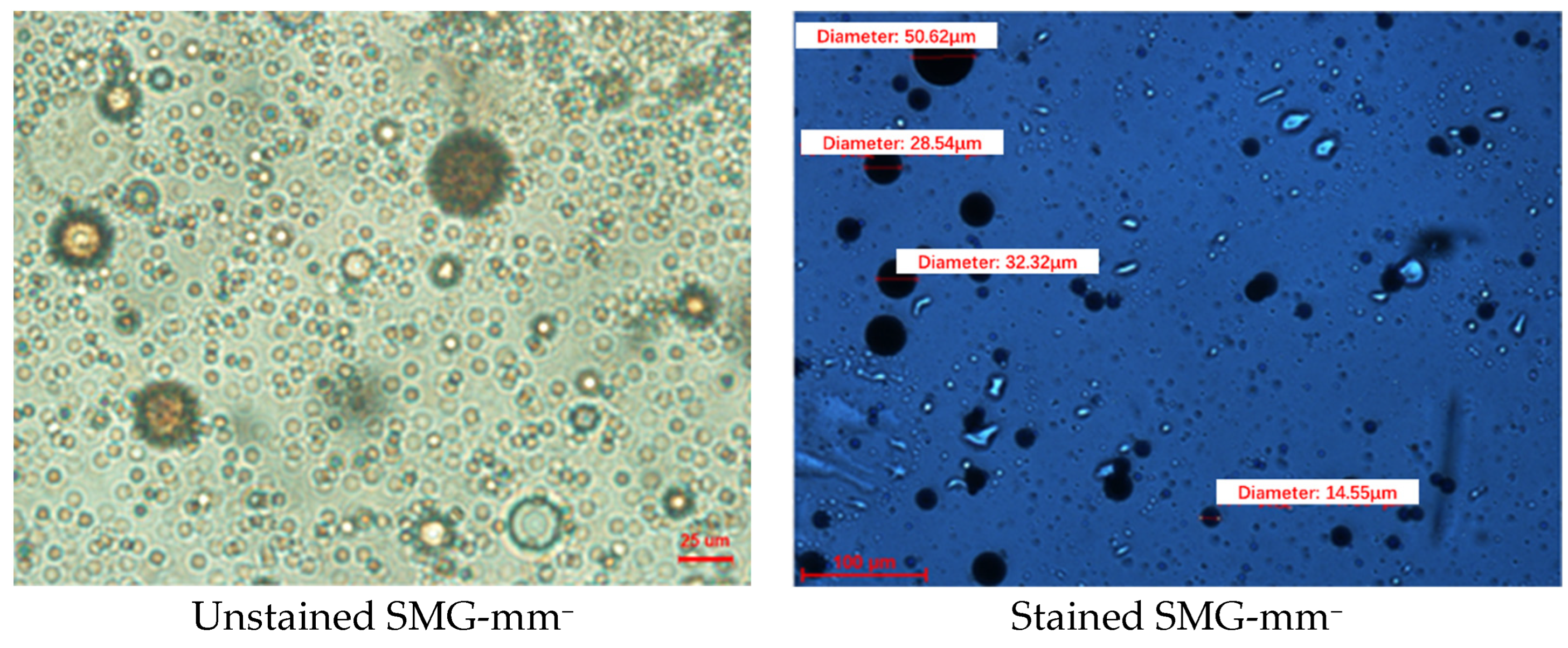
Figure 1. Micromorphology of SMG-mm under microscope.
Gels 09 00177 g001
Figure 2. The relationship between the apparent viscosity of SMG aqueous dispersion and shear rate.
Gels 09 00177 g002
Figure 3. Schematic diagram of the flexible particle system stationary and flowing through the pore.
Gels 09 00177 g003
Figure 4. Photos of the microscopic experiment of pore scale slit model.
Gels 09 00177 g004
Figure 5. The SMG profile control and oil displacement experiment results for the visual sand inclusion model.
Gels 09 00177 g005
Figure 6. The experiment results of matching between SMG-μm and reservoir.
Gels 09 00177 g006
Figure 7. The experiment results of matching between SMG-mm and reservoir.
Gels 09 00177 g007aGels 09 00177 g007b
Figure 8. The pressure curve the SMG-μm aqueous dispersion injection stage.
Gels 09 00177 g008aGels 09 00177 g008b
Figure 9. The pressure curve of the SMG-mm aqueous dispersion injection stage.
Gels 09 00177 g009aGels 09 00177 g009b
Figure 10. Three test models. (a) “∞” shaped model, (b) Pore scale slit model, (c) Visual sand inclusion model.
Gels 09 00177 g010
Figure 11. Schematic diagram of plane model and micro-model visual displacement equipment.
Gels 09 00177 g011
Table 1. Swelling property of SMG.
Typed0, μmdmax, μmB = (dmaxd0)/d0
SMG-μm3.228.67.9
SMG-mm16.668.33.1
Table 2. The matching results between SMG-μm and reservoir.
Permeability/(mD)Matching CoefficientFRFRRPlugging Rate
1001.6910.26.490.2
2501.409.07.288.9
5001.239.69.189.6
10000.9810.712.990.6
15000.839.49.789.4
20000.656.55.785.1
25000.554.34.976.7
Table 3. The matching results between SMG-mm and reservoir.
Permeability/(mD)Matching CoefficientFRFRRPlugging Rate
2502.6719.915.395.1
5002.0717.211.994.2
10001.6716.113.293.8
15001.5515.514.793.6
20001.3212.913.592.3
25001.1710.48.990.4
30000.888.97.588.8
40000.754.75.878.9
Table 4. The parameter for the artificial core.
Core NumberLength/cmDiameter/cmPorosity/%Permeability/mD
2-110.052.5118.5100
2-210.032.5020.1250
2-310.052.5222.0500
2-410.012.5124.81000
2-510.022.5025.81500
2-610.032.5126.62000
2-710.022.5029.12500
3-110.042.5322.2250
3-210.022.5323.8500
3-310.032.5024.81000
3-410.022.5126.81500
3-510.052.5227.42000
3-610.062.5327.92500
3-710.082.5129.53000
3-810.102.5132.94000
Table 5. The ionic composition of the stimulated brine.
Ionic CompositionNa+, K+Ca2+Mg2+CO32−HCO3SO42−ClTDS
Concentration, mg/L3091.96276.17158.6814.21311.4885.295436.349374.13
Disclaimer/Publisher’s Note: The statements, opinions and data contained in all publications are solely those of the individual author(s) and contributor(s) and not of MDPI and/or the editor(s). MDPI and/or the editor(s) disclaim responsibility for any injury to people or property resulting from any ideas, methods, instructions or products referred to in the content.