


Design and Development of Fluorinated and Biocide-Free Sol–Gel Based Hybrid Functional Coatings for Anti-Biofouling/Foul-Release Activity


 ,
,  ,
,  ,
,  ,
,  ,
,  , ,
, ,  and
and 
Abstract
:1. Introduction
2. Results and Discussion
2.1. Characterization of Sol–Gel Coated Glass Slides
2.1.1. FT-IR Analysis
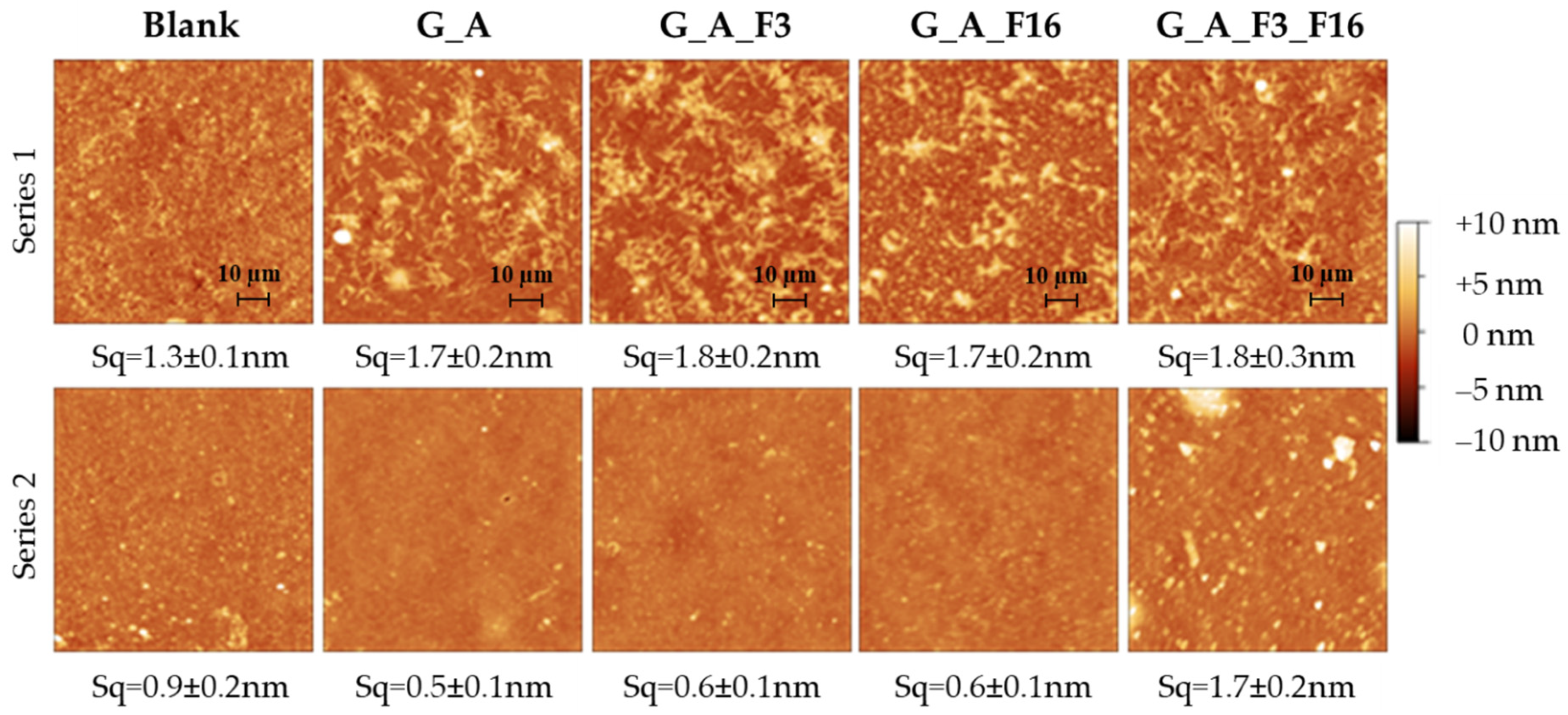
2.1.2. Morphological and Topography Characterization
2.2. Characterization of Sol–Gel Colloidal Solutions
2.3. Evaluation of Antifouling Properties and Characterization
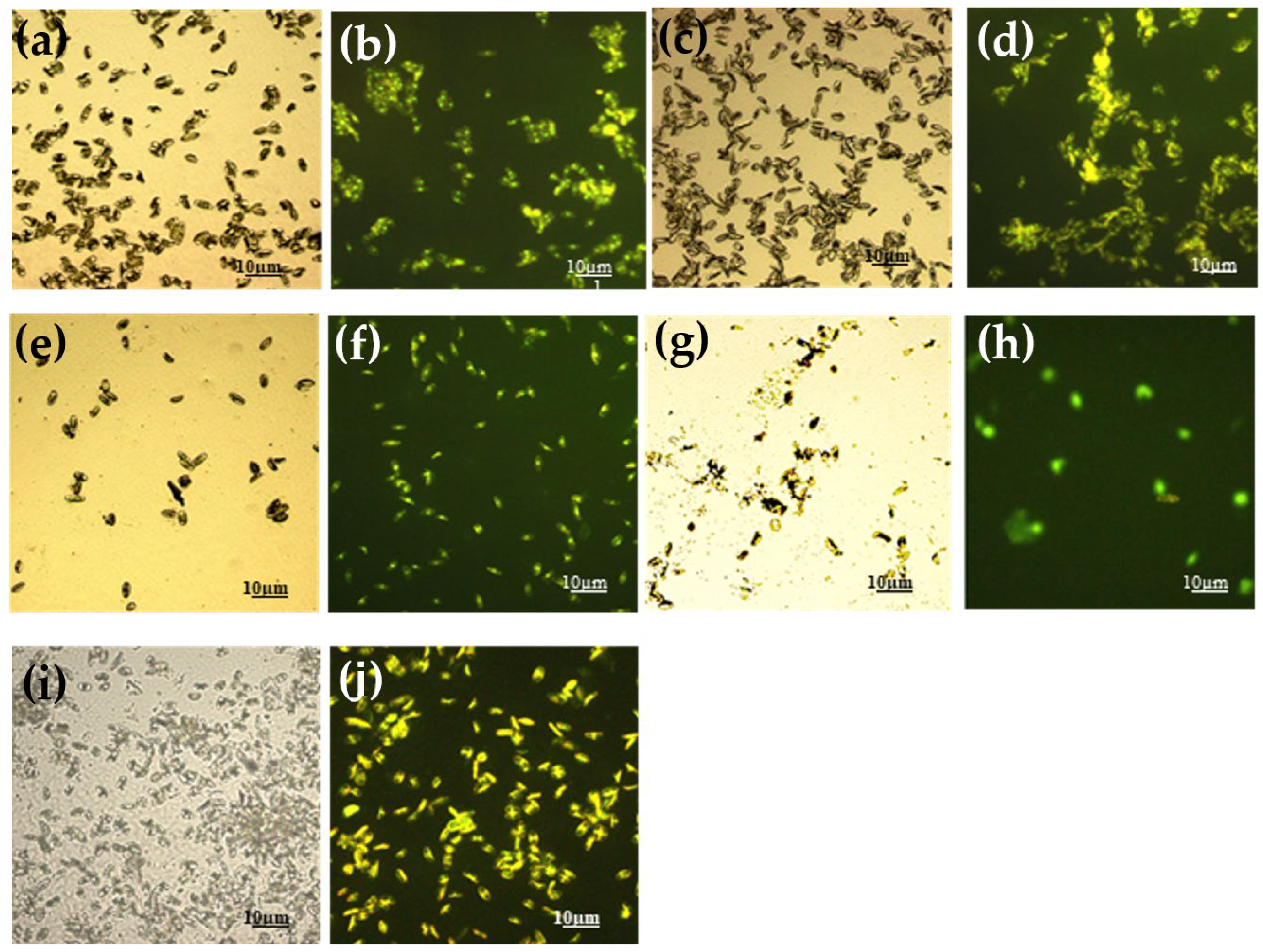
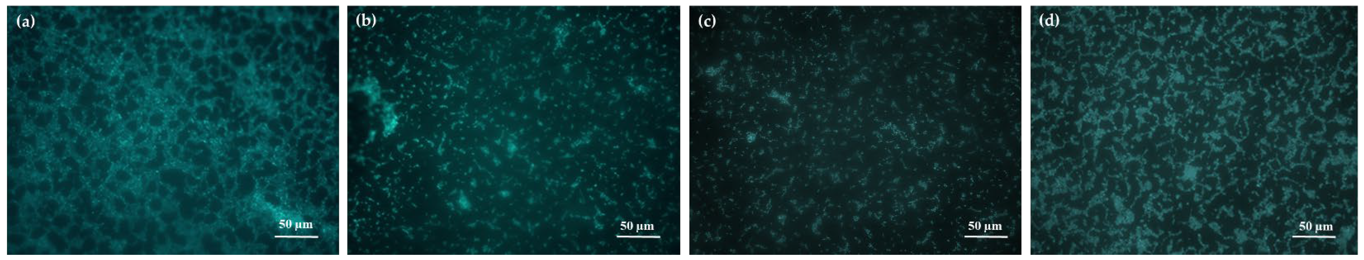
2.3.1. LM and EM
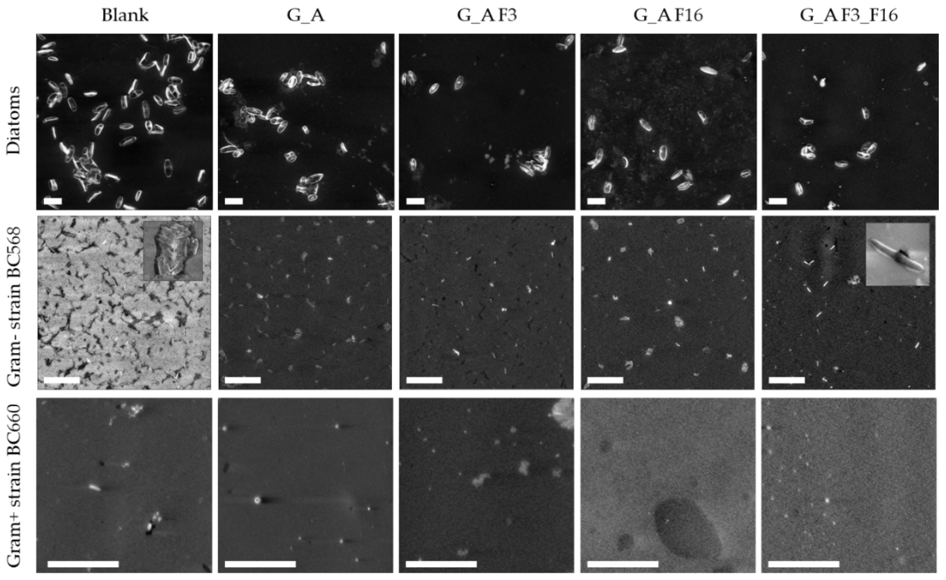
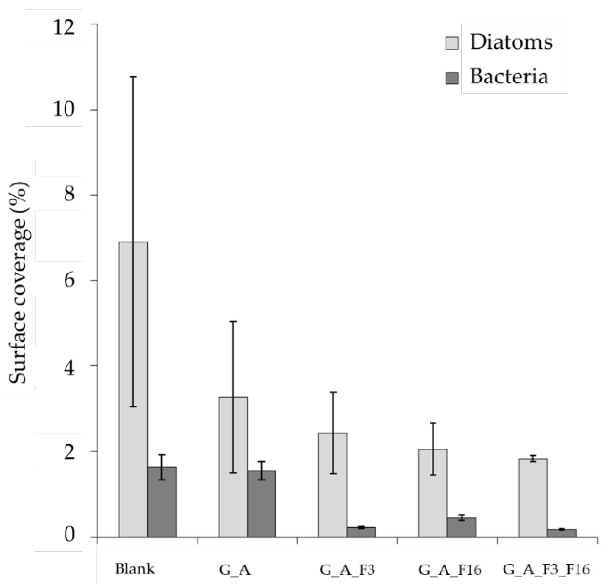
2.3.2. Morphological Characterization: Scanning Electron Microscopy (SEM)
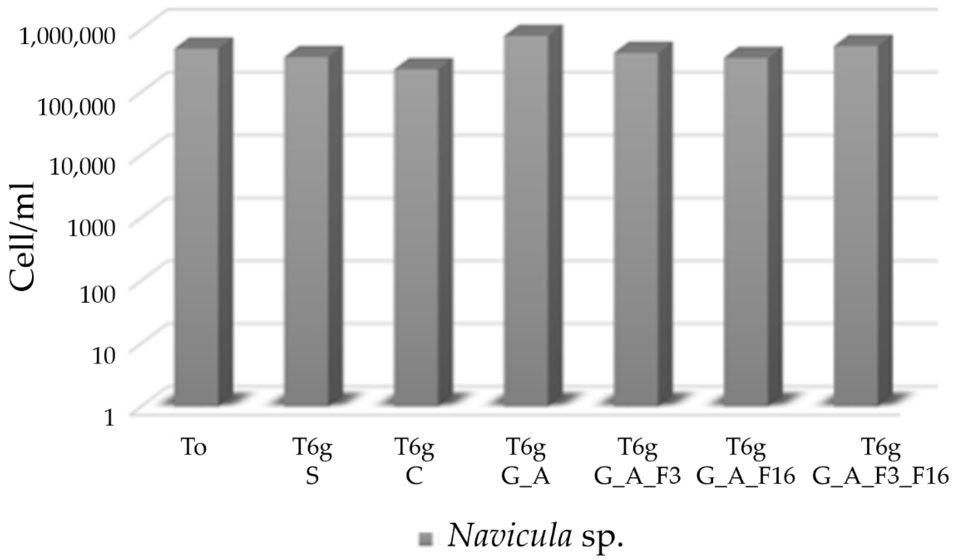
2.4. Evaluation of Toxicity of the Coating against Bacteria and Diatoms
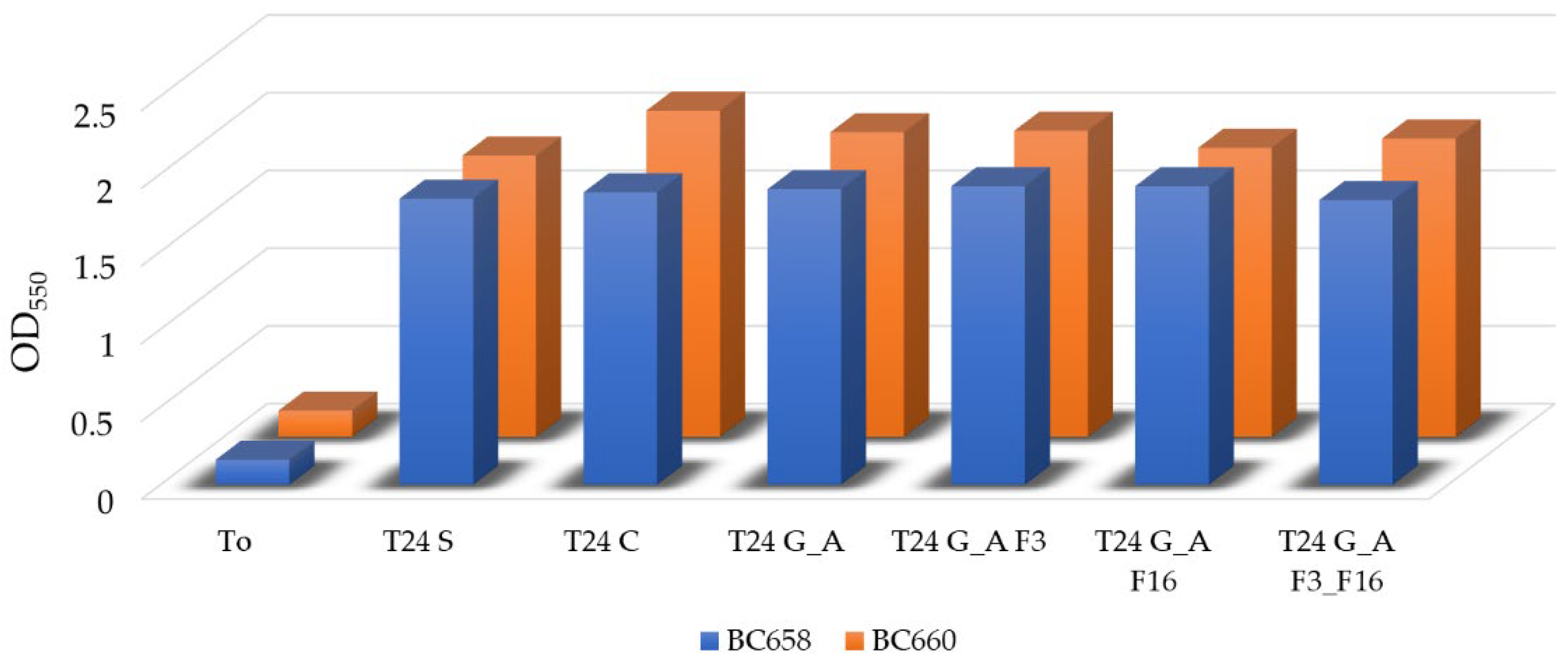
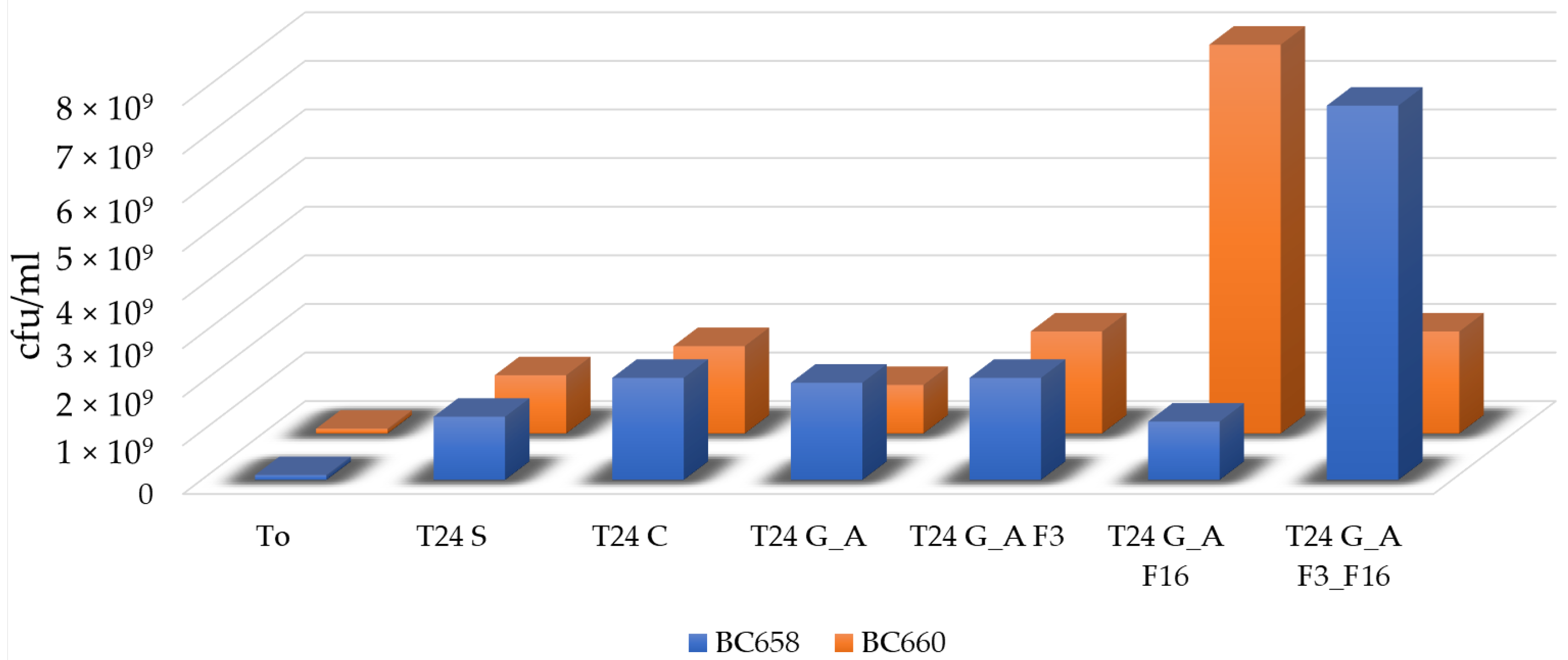
Bacterial Adhesion Tests in Simulation Experiment
3. Conclusions
4. Materials and Methods
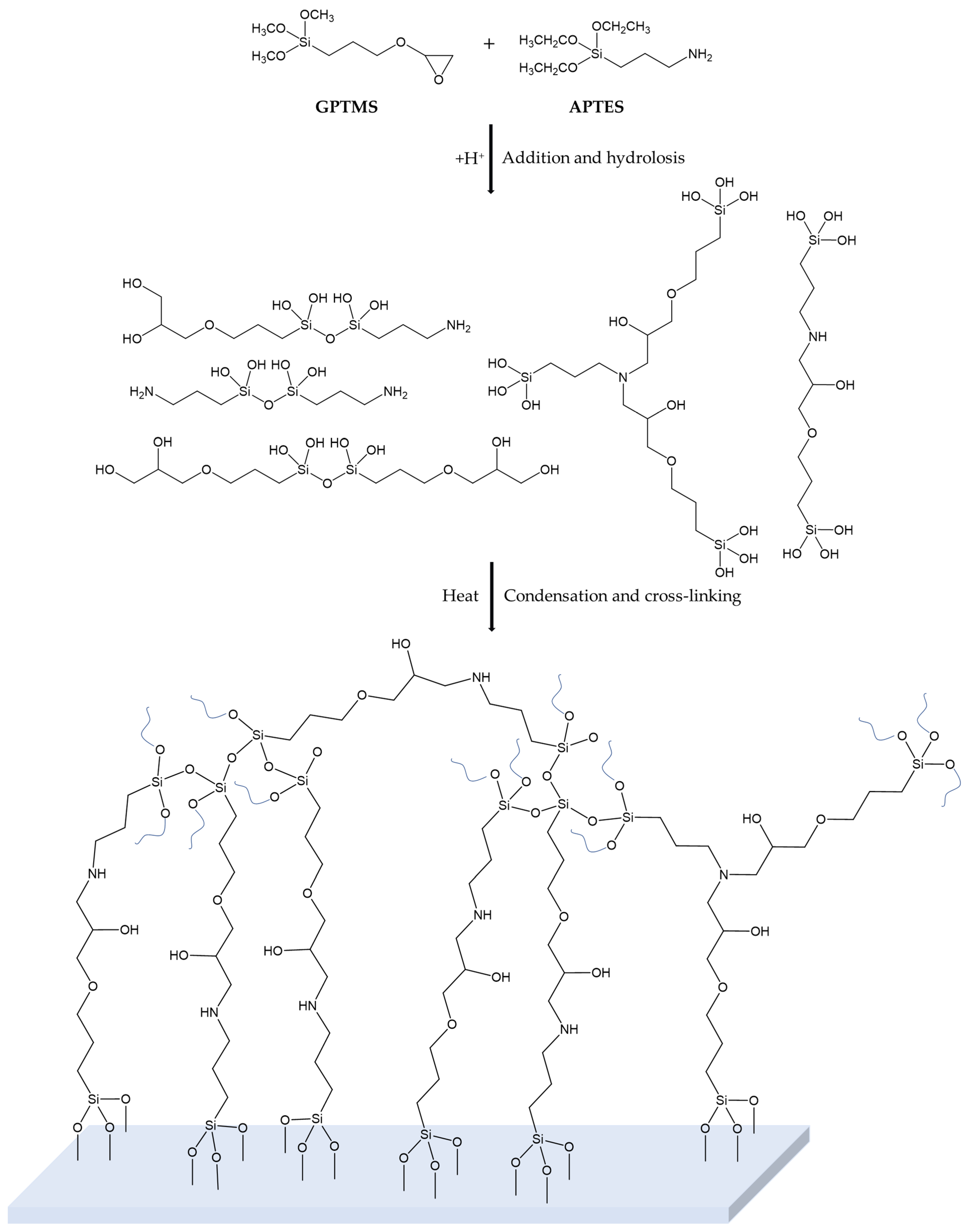
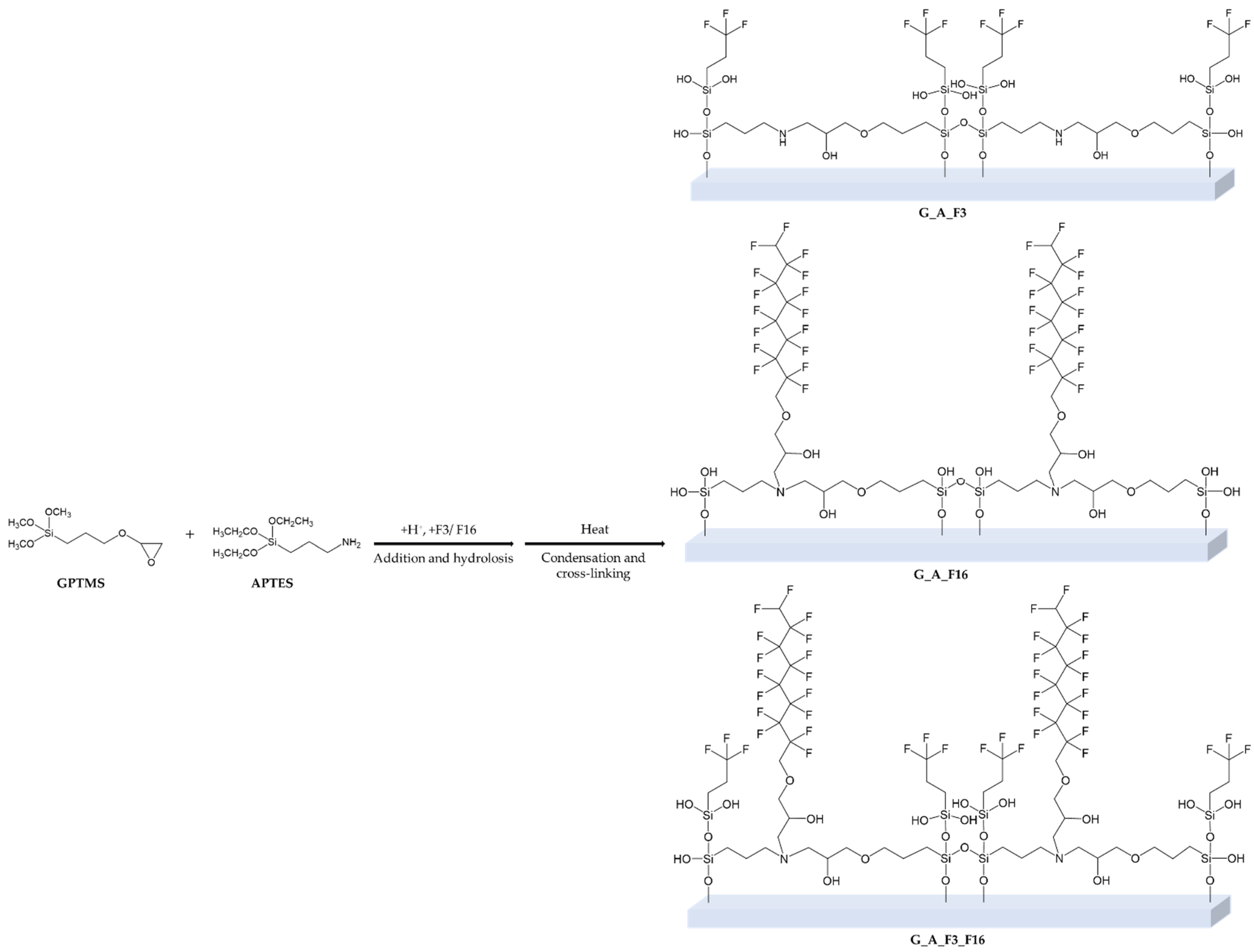
4.1. Sol–Gel Synthesis and Application
4.2. Characterization
4.3. Evaluation of Antifouling Properties and Toxicity of the Coatings
4.3.1. Strains and Culture Media
4.3.2. Microbial Suspensions
4.3.3. Antifouling and Biocide-Release Assessment
4.3.4. Microbial Adhesion Assessment
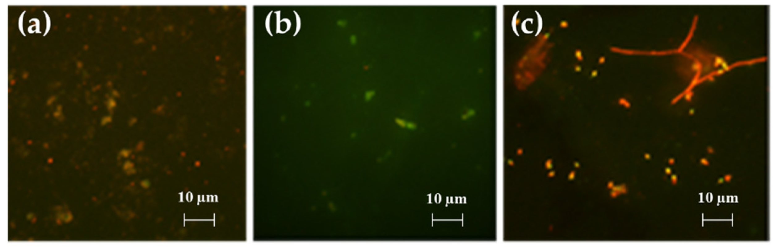
- (a)
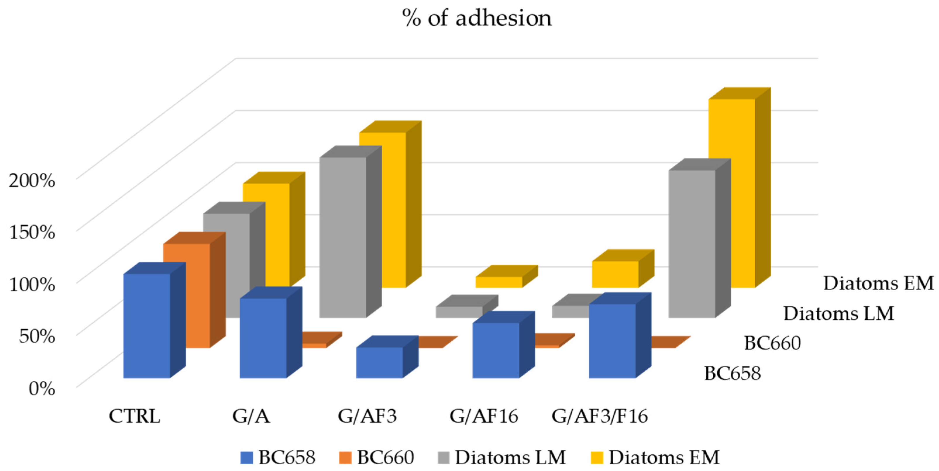
- For LM and EM were performed in a LEICA DM RE equipped with a video camera (LEICA DC 300 F). For each slide, 3 different images of different fields were acquired through the software Leica QWin Color (RGB). After, images were cut to obtain a final dimension of 602 × 602 μm and treated by using the plugin threshold [86] of Image J. 1.52c. In this way, both the number and percentage of the covered surface were determined for each field. The number of cells counted on the untreated glasses was considered as 100% of cells that could adhere to the glass substrate and thus the other cells counting adhering to the different coatings could be more similar or less than 100%, meaning, respectively, an attractive, similar or a repulsive action toward the microorganisms.
- (b)
- SEM images were obtained on a Zeiss EVO LS10 SEM equipped with a LaB6 thermionic electron source and a variable pressure secondary electron detector. No additional treatment was performed prior to SEM observation of samples, which were kept at 3.0 × 10⁻¹ Torr during measurements. Images obtained under both microscope observations were analyzed with Image J 1.52c. Surface densities were estimated by counting individual adhered organisms in at least five randomly selected 100 × 100 μm fields on each sample. The average area of adhered diatoms and bacteria was estimated by measuring 20 individual organisms of each type. In each case, standard deviation was used as the error.
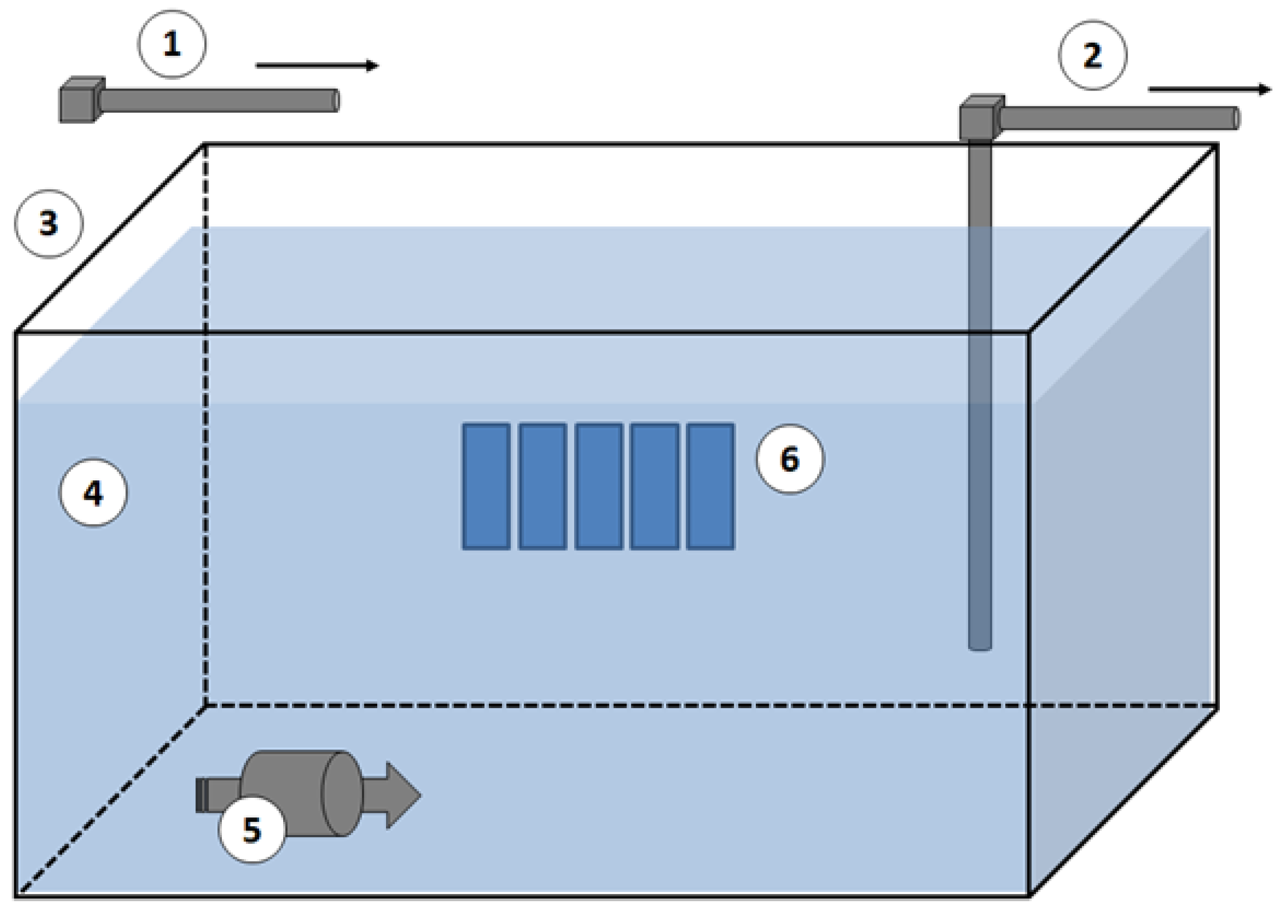
4.4. Bacterial Adhesion Tests in Microcosm Experiment
Author Contributions
Funding
Institutional Review Board Statement
Informed Consent Statement
Data Availability Statement
Acknowledgments
Conflicts of Interest
References
- Qiu, H.; Feng, K.; Gapeeva, A.; Meurisch, K.; Kaps, S.; Li, X.; Yu, L.; Mishra, Y.K.; Adelung, R.; Baum, M. Functional polymer materials for modern marine biofouling control. Prog. Polym. Sci. 2022, 127, 101516. [Google Scholar]
- Xu, S.J.; Chen, G.E.; Xu, Z.L. Excellent anti-fouling performance of PVDF polymeric membrane modified by enhanced CaA gel-layer. J. Ind. Eng. Chem. 2018, 58, 179–188. [Google Scholar]
- Ielo, I.; Giacobello, F.; Sfameni, S.; Rando, G.; Galletta, M.; Trovato, V.; Rosace, G.; Plutino, M.R. Nanostructured Surface Finishing and Coatings: Functional Properties and Applications. Materials 2021, 14, 2733. [Google Scholar]
- Ielo, I.; Giacobello, F.; Castellano, A.; Sfameni, S.; Rando, G.; Plutino, M.R. Development of Antibacterial and Antifouling Innovative and Eco-Sustainable Sol–Gel Based Materials: From Marine Areas Protection to Healthcare Applications. Gels 2022, 8, 26. [Google Scholar]
- Gao, X.; Yan, R.; Xu, L.; Ma, H. Effect of amorphous phytic acid nanoparticles on the corrosion mitigation performance and stability of sol-gel coatings on cold-rolled steel substrates. J. Alloy. Compd. 2018, 747, 747–754. [Google Scholar]
- Kwanyoung, K.; YoungJae, Y.; Min-Ji, K.; Jihyang, K.; Haegeun, C. Improvement in fouling resistance of silver-graphene oxide coated polyvinylidene fluoride membrane prepared by pressurized filtratio. Sep. Purif. Technol. 2018, 194, 161–169. [Google Scholar]
- Liu, Y.; Zhao, Y.J.; Teng, J.L.; Wang, J.H.; Wu, L.S.; Zheng, Y.L. Research progress of nano self-cleaning anti-fouling coatings. IOP Conf. Ser. Mater. Sci. Eng. 2017, 284, 012016. [Google Scholar]
- Amini, S.; Kolle, S.; Petrone, L.; Ahanotu, O.; Sunny, S.; Sutanto, C.N.; Hoon, S.; Cohen, L.; Weaver, J.C.; Aizenberg, J.; et al. Preventing mussel adhesion using lubricant-infused materials. Science 2017, 357, 668–673. [Google Scholar]
- Silva, E.; Tulcidas, A.V.; Ferreira, O.; Bayón, R.; Igartua, A.; Mendoza, G.; Mergulhão, F.J.M.; Faria, S.I.; Gomes, L.C.; Carvalho, S.; et al. Assessment of the environmental compatibility and antifouling performance of an innovative biocidal and foul-release multifunctional marine coating. Environ. Res. 2021, 198, 111219. [Google Scholar]
- Gu, Y.; Yu, L.; Mou, J.; Wu, D.; Xu, M.; Zhou, P.; Ren, Y. Research Strategies to Develop Environmentally Friendly Marine Antifouling Coatings. Mar. Drugs 2020, 18, 371. [Google Scholar]
- Silva, E.R.; Ferreira, O.; Ramalho, P.A.; Azevedo, N.F.; Bayón, R.; Igartua, A.; Bordado, J.C.; Calhorda, M.G. Eco-friendly non-biocide-release coatings for marine biofouling prevention. Sci. Total Environ. 2019, 650, 2499–2511. [Google Scholar]
- Ulaeto, S.B.; Pancrecious, J.K.; Rajan, T.P.D.; Pai, B.C. Smart Coatings. Noble Met-Met. Oxide Hybrid Nanopart. 2019, 17, 341–372. [Google Scholar]
- Nurioglu, A.G.; Carvalho Esteves, A.C.; With, G. Non-toxic, non-biocide-release antifouling coatings based on molecular structure design for marine applications. J. Mater. Chem. B 2015, 3, 6547. [Google Scholar]
- Salta, M.; Wharton, J.A.; Stoodley, P.; Dennington, S.P.; Goodes, L.R.; Werwinski, S.; Mart, U.; Wood, R.J.K.; Stokes, K.R. Designing biomimetic antifouling surfaces. Phil. Trans. R. Soc. A 2010, 368, 4729–4754. [Google Scholar]
- Nisol, B.; Lerouge, S.; Watson, S.; Meunier, A.; Wertheimer, M.R. Energetics of reactions in a dielectric barrier discharge with argon carrier gas: VI PEG-like coatings. Plasma Process Polym. 2017, 15, 1700132. [Google Scholar]
- Zouaghi, S.; Six, T.; Bellayera, S.; Coffinier, Y.; Abdallah, M.; Chihib, N.E.; Andréa, C.; Delaplace, G.; Jimenez, M. Atmospheric pressure plasma spraying of silane-based coatings targeting whey protein fouling and bacterial adhesion management. Appl. Surf. Sci. 2018, 455, 392–402. [Google Scholar]
- Dong, W.; Qian, F.; Li, Q.; Tang, G.; Xiang, T.; Chun, T.; Lu, J.; Han, Y.; Xia, Y.; Hu, J. Fabrication of superhydrophobic PET filter material with fluorinated SiO2 nanoparticles via simple sol–gel process. J. Sol-Gel Sci. Technol. 2021, 98, 224–237. [Google Scholar]
- Tang, Y.; Zhang, Q.; Zhan, X.; Chen, F. Superhydrophobic and anti-icing properties at overcooled temperature of a fluorinated hybrid surface prepared via a sol-gel process. Soft Matter 2015, 11, 4540–4550. [Google Scholar]
- Mielczarski, J.A.; Mielczarski, E.; Galli, G.; Morelli, A.; Martinelli, E.; Chiellini, E. The Surface-Segregated Nanostructure of Fluorinated Copolymer-Poly(dimethylsiloxane) Blend Films. Langmuir 2010, 26, 2871–2876. [Google Scholar]
- Kim, J.; Kim, C.; Baek, Y.; Hong, S.P.; Kim, H.J.; Lee, J.C.; Yoon, J. Facile surface modification of a polyamide reverse osmosis membrane using a TiO2 sol-gel derived spray coating method to enhance the anti-fouling property. Desalin. Water Treat. 2018, 102, 9–15. [Google Scholar]
- Bai, X.; Li, J.; Zhu, L.; Wang, L. Effect of Cu content on microstructure, mechanical and anti-fouling properties of TiSiN-Cu coating deposited by multi-arc ion plating. Appl. Surf. Sci. 2018, 427, 444–451. [Google Scholar]
- Xin, L.; Jiansheng, L.; Bart, V.; Xiuyun, S.; Jinyou, S.; Weiqing, H.; Lianjun, W. Fouling behavior of polyethersulfone ultrafiltration membranes functionalized with sol–gel formed ZnO nanoparticles. RSC Adv. 2015, 5, 50711. [Google Scholar]
- Munch, A.S.; Wolk, M.; Malanin, M.; Eichhorn, K.J.; Simon, F.; Uhlmann, P. Smart functional polymer coatings for paper with anti-fouling properties. J. Mater. Chem. B 2018, 6, 830. [Google Scholar]
- Reverdy, C.; Belgacem, N.; Moghaddam, M.S.; Sundin, M.; Swerin, A.; Bras, J. One-step superhydrophobic coating using hydrophobized cellulose nanofibrils. Colloids Surf. A Physicochem. Eng. Asp. 2018, 544, 152–158. [Google Scholar]
- Pieper, R.J.; Ekin, A.; Webster, D.C.; Casse, F.; Callow, J.A.; Callow, M.E. Combinatorial approach to study the effect of acrylic polyol composition on the properties of crosslinked siloxane-polyurethane fouling-release coatings. J. Coat. Technol. Res. 2017, 4, 453–461. [Google Scholar]
- Lin, X.; Yang, M.; Jeong, H.; Chang, M.; Hong, J. Durable superhydrophilic coatings formed for anti-biofouling and oil–water separation. J. Memb. Sci. 2016, 506, 22–30. [Google Scholar]
- Plutino, M.R.; Colleoni, C.; Donelli, I.; Freddi, G.; Guido, E.; Maschi, O.; Mezzi, A.; Rosace, G. Sol-gel 3-glycidoxypropyltriethoxysilane finishing on different fabrics: The role of precursor concentration and catalyst on the textile performances and cytotoxic activity. J. Colloid Interface Sci. 2017, 506, 504–517. [Google Scholar]
- Abou Elmaaty, T.; Elsisi, H.G.; Elsayad, G.M.; Elhadad, H.H.; Sayed-Ahmed, K.; Plutino, M.R. Fabrication of New Multifunctional Cotton/Lycra Composites Protective Textiles through Deposition of Nano Silica Coating. Polymers 2021, 13, 2888. [Google Scholar]
- Puoci, F.; Saturnino, C.; Trovato, V.; Iacopetta, D.; Piperopoulos, E.; Triolo, C.; Bonomo, M.G.; Drommi, D.; Parisi, O.I.; Milone, C.; et al. Sol–Gel Treatment of Textiles for the Entrapping of an Antioxidant/Anti-Inflammatory Molecule: Functional Coating Morphological Characterization and Drug Release Evaluation. Appl. Sci. 2020, 10, 2287. [Google Scholar]
- Trovato, V.; Mezzi, A.; Brucale, M.; Rosace, G.; Plutino, M.R. Alizarin-functionalized organic-inorganic silane coatings for the development of wearable textile sensors. J. Colloid Interface Sci. 2022, 617, 463–477. [Google Scholar]
- Trovato, V.; Mezzi, A.; Brucale, M.; Abdeh, H.; Drommi, D.; Rosace, G.; Plutino, M.R. Sol-Gel Assisted Immobilization of Alizarin Red S on Polyester Fabrics for Developing Stimuli-Responsive Wearable Sensors. Polymers 2022, 14, 2788. [Google Scholar] [CrossRef]
- Chobba, M.B.; Weththimuni, M.L.; Messaoud, M.; Urzì, C.; Bouaziz, J.; De Leo, F.; Licchelli, M. Ag-TiO2/PDMS nanocomposite protective coatings: Synthesis, characterization, and use as a self-cleaning and antimicrobial agent. Prog. Org. Coat. 2021, 158, 106342. [Google Scholar]
- Iannazzo, D.; Pistone, A.; Visco, A.; Galtieri, G.; Giofrè, S.V.; Romeo, R.; Romeo, G.; Cappello, S.; Bonsignore, M.; Denaro, R. 1,2,3-Triazole/MWCNT Conjugates as Filler for Gelcoat Nanocomposites: New Active Antibiofouling Coatings for Marine. Appl. Mater. Res. Express 2015, 2, 115001. [Google Scholar]
- Pistone, A.; Scolaro, C.; Visco, A. Mechanical Properties of Protective Coatings against Marine Fouling: A Review. Polymer 2021, 13, 173. [Google Scholar]
- Pistone, A.; Visco, A.; Galtieri, G.; Iannazzo, D.; Espro, C.; Marino Merlo, F.; Urzì, C.; De Leo, F. Polyester resin and carbon nanotubes based nanocomposite as new-generation coating to prevent biofilm formation. Int. J. Polym. Anal. Charact. 2016, 21, 327–336. [Google Scholar]
- Celesti, C.; Gervasi, T.; Cicero, N.; Giofrè, S.V.; Espro, C.; Piperopoulos, E.; Gabriele, B.; Mancuso, R.; Lo Vecchio, G.; Iannazzo, D. Titanium Surface Modification for Implantable Medical Devices with Anti-Bacterial Adhesion Properties. Materials 2022, 15, 3283. [Google Scholar]
- Krzak, J.; Szczurek, A.; Babiarczuk, B.; Gąsiorek, J.; Borak, B. Chapter 5—Sol–gel surface functionalization regardless of form and type of substrate. In Handbook of Nanomaterials for Manufacturing Applications; Hussain, C.M., Ed.; Micro and Nano Technologies; Elsevier: Amsterdam, The Netherlands, 2020; pp. 111–147. ISBN 978-0-12-821381-0. [Google Scholar]
- Fotovvati, B.; Namdari, N.; Dehghanghadikolaei, A. On Coating Techniques for Surface Protection: A Review. J. Manuf. Mater. Process. 2019, 3, 28. [Google Scholar]
- Figueira, R.B. Hybrid Sol–gel Coatings for Corrosion Mitigation: A Critical Review. Polymers 2020, 12, 689. [Google Scholar]
- Rando, G.; Sfameni, S.; Galletta, M.; Drommi, D.; Cappello, S.; Plutino, M.R. Functional Nanohybrids and Nanocomposites Development for the Removal of Environmental Pollutants and Bioremediation. Molecules 2022, 27, 4856. [Google Scholar]
- Ielo, I.; Galletta, M.; Rando, G.; Sfameni, S.; Cardiano, P.; Sabatino, G.; Drommi, D.; Rosace, G.; Plutino, M.R. Design, synthesis and characterization of hybrid coatings suitable for geopolymeric-based supports for the restoration of cultural heritage. IOP Conf. Ser. Mater. Sci. Eng. 2020, 777, 012003. [Google Scholar]
- Trovato, V.; Rosace, G.; Colleoni, C.; Sfameni, S.; Migani, V.; Plutino, M.R. Sol-gel based coatings for the protection of cultural heritage textiles. IOP Conf. Ser. Mater. Sci. Eng. 2020, 777, 012007. [Google Scholar]
- Rosace, G.; Guido, E.; Colleoni, C.; Brucale, M.; Piperopoulos, E.; Milone, C.; Plutino, M.R. Halochromic resorufin-GPTMS hybrid sol-gel: Chemical-physical properties and use as pH sensor fabric coating. Sens. Actuators B Chem. 2017, 241, 85–95. [Google Scholar] [CrossRef]
- Trovato, V.; Colleoni, C.; Castellano, A.; Plutino, M.R. The key role of 3-glycidoxypropyltrimethoxysilane sol–gel precursor in the development of wearable sensors for health monitoring. J. Sol-Gel Sci. Technol. 2018, 87, 27–40. [Google Scholar] [CrossRef]
- Giacobello, F.; Ielo, I.; Belhamdi, H.; Plutino, M.R. Geopolymers and Functionalization Strategies for the Development of Sustainable Materials in Construction Industry and Cultural Heritage Applications: A Review. Materials 2022, 15, 1725. [Google Scholar] [CrossRef]
- Cardiano, P.; Schiavo, S.L.; Piraino, P. Hydrorepellent properties of organic–inorganic hybrid materials. J. Non-Cryst. Solids 2010, 356, 917–926. [Google Scholar] [CrossRef]
- Cardiano, P. Hydrophobic properties of new epoxy-silica hybrids. J. Appl. Polym. Sci. 2008, 108, 3380–3387. [Google Scholar] [CrossRef]
- Pistone, A.; Scolaro, C.; Celesti, C.; Visco, A. Study of Protective Layers Based on Crosslinked Glutaraldehyde/3-aminopropyltriethoxysilane. Polymers 2022, 14, 801. [Google Scholar]
- Galiano, F.; Schmidt, S.A.; Ye, X.; Kumar, R.; Mancuso, R.; Curcio, E.; Gabriele, B.; Hoinkis, J.; Figoli, A. UV-LED induced bicontinuous microemulsions polymerisation for surface modification of commercial membranes—Enhancing the antifouling properties. Sep. Purif. Technol. 2018, 194, 149–160. [Google Scholar]
- Dett, M.R.; Ciriminna, R.; Bright, F.V.; Pagliaro, M. Environmentally Benign Sol-Gel Antifouling and Foul-Releasing Coatings. Acc. Chem. Res. 2014, 47, 678–687. [Google Scholar]
- Donnelly, B.; Sammut, K.; Tang, Y. Materials Selection for Antifouling Systems in Marine Structures. Molecules 2022, 27, 3408. [Google Scholar]
- Chen, J.; Jian, R.; Yang, K.; Bai, W.; Huang, C.; Lin, Y.; Zheng, B.; Wei, F.; Lin, Q.; Xu, Y. Urushiol-based benzoxazine copper polymer with low surface energy, strong substrate adhesion and antibacterial for marine antifouling application. J. Clean. Prod. 2021, 318, 128527. [Google Scholar]
- Sfameni, S.; Rando, G.; Marchetta, A.; Scolaro, C.; Cappello, S.; Urzì, C.; Visco, A.; Plutino, M.R. Development of eco-friendly hydrophobic and fouling-release coatings for blue-growth environmental applications: Synthesis, mechanical characterization and biological activity. Gels 2022, 8, 528. [Google Scholar] [CrossRef]
- Callow, J.A.; Callow, M.E. Trends in the development of environmentally friendly fouling-resistant marine coatings. Nat. Commun. 2011, 2, 244. [Google Scholar]
- Callow, M.E.; Fletcher, R.L. The influence of low surface energy materials on bioadhesion—A review. Int. Biodeterior. Biodegrad. 1994, 34, 333–348. [Google Scholar]
- Maan, A.M.C.; Hofman, A.H.; de Vos, W.M.; Kamperman, M. Recent Developments and Practical Feasibility of Polymer-Based Antifouling Coatings. Adv. Funct. Mater. 2020, 30, 2000936. [Google Scholar]
- Barletta, M.; Aversa, C.; Pizzi, E.; Puopolo, M.; Vesco, S. Design, manufacturing and testing of anti-fouling/foul-release (AF/FR) amphiphilic coatings. Prog. Org. Coat. 2018, 123, 267–281. [Google Scholar]
- Zhou, Z.; Calabrese, D.R.; Taylor, W.; Finlay, J.A.; Callow, M.E.; Callow, J.A.; Fischer, D.; Kramer, E.J.; Ober, C.K. Amphiphilic triblock copolymers with PEGylated hydrocarbon structures as environmentally friendly marine antifouling and fouling-release coatings. Biofouling 2014, 30, 589–604. [Google Scholar]
- Rodríguez-Hernández, J. Chapter 11—Nano/Micro and Hierarchical Structured Surfaces in Polymer Blends. In Nanostructured Polymer Blends; Thomas, S., Shanks, R., Chandrasekharakurup, S.B.T.-N.P.B., Eds.; William Andrew Publishing: Oxford, UK, 2014; pp. 357–421. ISBN 978-1-4557-3159-6. [Google Scholar]
- Galli, G.; Martinelli, E. Amphiphilic Polymer Platforms: Surface Engineering of Films for Marine Antibiofouling. Macromol. Rapid Commun. 2017, 38, 1600704. [Google Scholar]
- Karnati, S.; Oldham, D.; Fini, E.H.; Zhang, L. Application of surface-modified silica nanoparticles with dual silane coupling agents in bitumen for performance enhancement. Constr. Build. Mater. 2020, 244, 118324. [Google Scholar]
- Nečas, D.; Klapetek, P. Gwyddion: An open-source software for SPM data analysis. Cent. Eur. J. Phys. 2012, 10, 181–188. [Google Scholar]
- Langer, R. Drug delivery and targeting. Nature 1998, 392, 5–10. [Google Scholar]
- Brouwers, J.R.B.J. Advanced and controlled drug delivery systems in clinical disease management. Pharm. World Sci. 1996, 18, 153–162. [Google Scholar]
- Uhrich, K.E.; Cannizzaro, S.M.; Langer, R.S.; Shakesheff, K.M. Polymeric Systems for Controlled Drug Release. Chem. Rev. 1999, 99, 3181–3198. [Google Scholar]
- Ferrero, F.; Periolatto, M. Application of fluorinated compounds to cotton fabrics via sol-gel. Appl. Surf. Sci. 2013, 275, 201–207. [Google Scholar]
- Ten Breteler, M.R.; Nierstrasz, V.A.; Warmoeskerken, M.M.C.G. Textile Slow-Release Systems with Medical Applications. AUTEX Res. J. 2002, 2, 175–189. [Google Scholar]
- Brannon-Peppas, L. Controlled Release in the Food and Cosmetics Industries; ACS Publications: Washington, DC, USA, 1993; pp. 42–52. [Google Scholar]
- Mansur, H.S.; Oréfice, R.L.; Vasconcelos, W.L.; Lobato, Z.P.; Machado, L.J.C. Biomaterial with chemically engineered surface for protein immobilization. J. Mater. Sci. Mater. Med. 2005, 16, 333–340. [Google Scholar]
- Amiri, A.; Sharifian, P.; Soltanizadeh, N. Application of ultrasound treatment for improving the physicochemical, functional and rheological properties of myofibrillar proteins. Int. J. Biol. Macromol. 2018, 111, 139–147. [Google Scholar]
- Hu, Z.; Haruna, M.; Gao, H.; Nourafkan, E.; Wen, D. Rheological properties of partially hydrolyzed polyacrylamide seeded by nanoparticles. Ind. Eng. Chem. Res. 2017, 56, 3456–3463. [Google Scholar]
- Wang, Z.; Zuilhof, H. Antifouling Properties of Fluoropolymer Brushes toward Organic Polymers: The Influence of Composition, Thickness, Brush Architecture, and Annealing. Langmuir 2016, 32, 6571–6581. [Google Scholar] [CrossRef] [Green Version]
- Lu, A.; Gao, Y.; Jin, T.; Luo, X.; Zeng, Q.; Shang, Z. Effects of surface roughness and texture on the bacterial adhesion on the bearing surface of bio-ceramic joint implants: An in vitro study. Ceram. Int. 2020, 46, 6550–6559. [Google Scholar]
- Khan, M.J.; Singh, R.; Shewani, K.; Shukla, P.; Bhaskar, P.V.; Joshi, K.B.; Vinayak, V. Exopolysaccharides directed embellishment of diatoms triggered on plastics and other marine litter. Sci. Rep. 2020, 10, 18448. [Google Scholar]
- Scardino, A.J.; Zhang, H.; Cookson, D.J.; Lamb, R.N.; Nys, R.D. The role of nano-roughness in antifouling. Biofouling 2009, 25, 757–767. [Google Scholar]
- Marmur, A.A. Guide to the Equilibrium Contact Angles Maze. In Contact angle, Wettability and Adhesion; CRC Press: Boca Raton, FL, USA, 2009; pp. 1–18. [Google Scholar]
- Wenzel, R.N. Resistance of solid surfaces to wetting by water. Ind. Eng. Chem. 1936, 28, 988–994. [Google Scholar]
- Scurria, A.; Scolaro, C.; Sfameni, S.; Di Carlo, G.; Pagliaro, M.; Visco, A.; Ciriminna, R. Towards AquaSun practical utilization: Strong adhesion and lack of ecotoxicity of solar-driven antifouling sol-gel coating. Prog. Org. Coat. 2022, 165, 106771. [Google Scholar]
- Cappello, S.; Calogero, R.; Santisi, S.; Genovese, M.; Denaro, R.; Genovese, L.; Giuliano, L.; Mancini, G.; Yakimov, M.M. Bioremediation of oil polluted marine sediments: A bio-engineering treatment. Int. Microbiol. 2015, 18, 127–134. [Google Scholar]
- Urzì, C.; De Leo, F. Sampling with adhesive tape strips: An easy and rapid method to monitor microbial colonization on monument surfaces. J. Microbiol. Methods 2001, 44, 1–11. [Google Scholar]
- Urzì, C.; Albertano, P. Studying phototrophic and heterotrophic microbial communities on stone monuments. Methods Enzymol. 2001, 336, 340–355. [Google Scholar]
- Dufour, A.P.; Strickland, E.R.; Cabelli, V.J. Membrane filter method for enumerating Escherichia coli. Appl. Environ. Microbiol. 1981, 41, 1152–1158. [Google Scholar]
- Urzì, C.; De Leo, F.; Krakova, L.; Pangallo, D.; Bruno, L. Effects of biocide treatments on the biofilm community in Domitilla’s catacombs in Rome. Sci. Total Environ. 2016, 572, 252–262. [Google Scholar]
- Urzì, C.; De Leo, F. Evaluation of the efficiency of water-repellent and biocide compoundsagainst microbial colonization of mortars. Int. Biodeterior. Biodegrad. 2007, 60, 25–34. [Google Scholar]
- La Cono, V.; Urzì, C. Fluorescent in situ hybridization applied on samples taken with adhesive tape strips. J. Microbiol. Methods 2003, 55, 65–71. [Google Scholar]
- Scandura, G.; Ciriminna, R.; Ozer, L.Y.; Meneguzzo, F.; Palmisano, G.; Pagliaro, M. Antifouling and Photocatalytic Antibacterial Activity of the AquaSun Coating in Seawater and Related Media. ACS Omega 2017, 2, 7568–7575. [Google Scholar]
- Porter, K.G.; Feig, Y.S. The use of DAPI for identifying and counting aquatic microflora. Limnol. Oceanogr. 1980, 25, 943–948. [Google Scholar]


| Wavenumbers (cm−1) | Reference | Vibrational Modes | |
|---|---|---|---|
| On the glass | From literature | ||
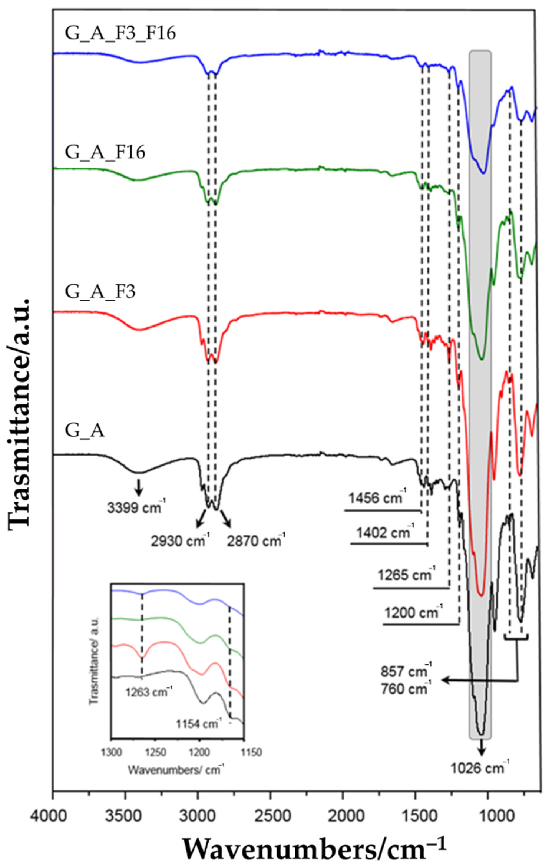
| 3399 | 3450–3261 | [63,64] | ν (N-H) |
| 2930–2870 | 2980–2800 | [65,66] | |
| 1456 | 1450 | ν (C-H) | |
| 1250 | 1263 | [67] | ν (C-F) in CF3 |
| 1206 | 1200 | [27,65] | ν (Si-O) |
| 1150 | 1154 | [66,67] | ν (C-F) in CF2 |
| 1026 | 1080 | [68,69] | (Si-O-Si) |
| 958 | 950 | [69,70] | (Si-OH) |
| 856 | 816–847 | [27,65] | ν (Si-O-Si) |
| 760 | 786–749 | [27,65] | νs (Si-O-Si) |
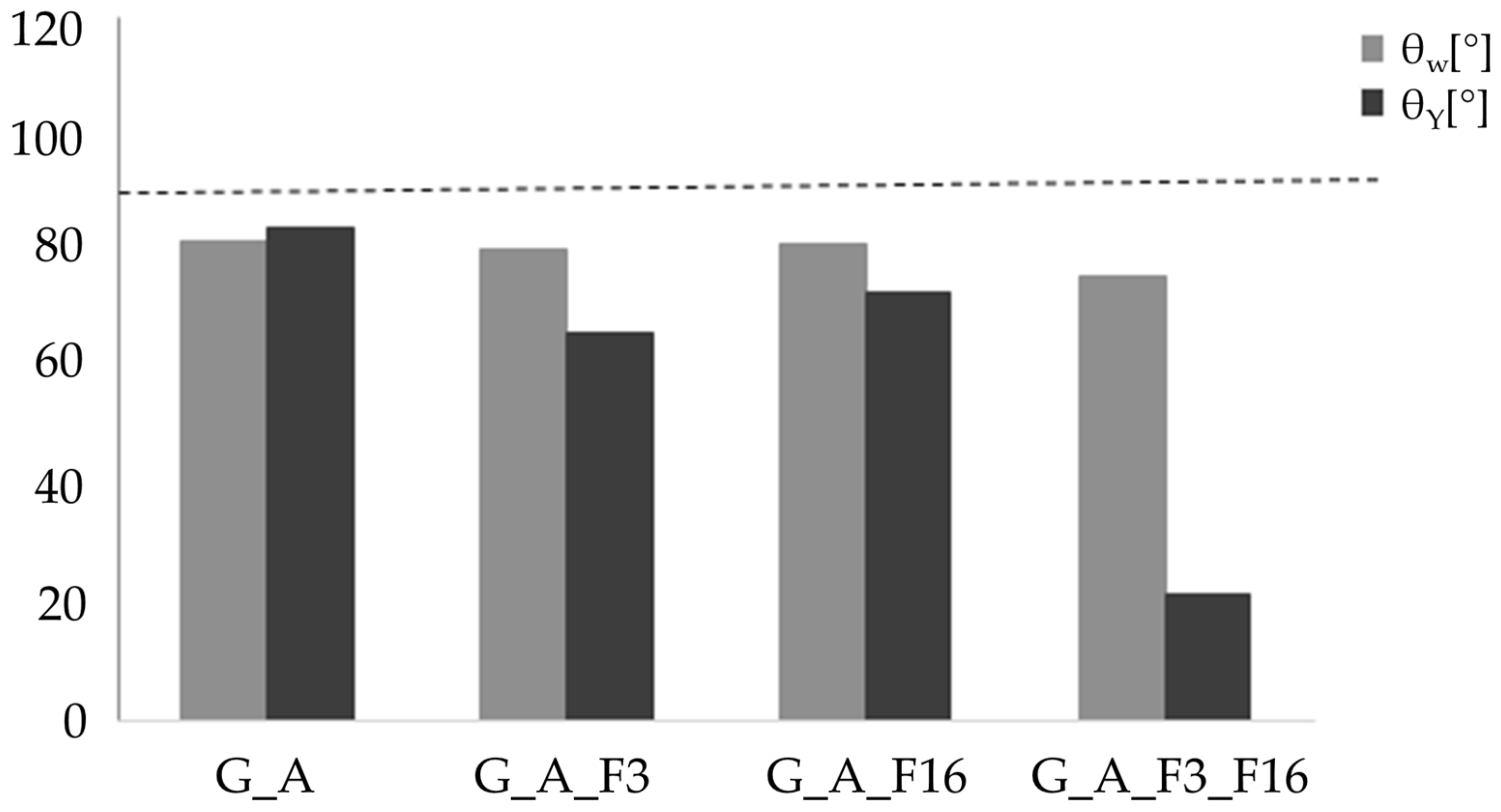
| Name | Ra [μm] | θW [°] | θY [°/μm] |
|---|---|---|---|
| G_A | 1.40 ± 0.01 | 81.84 ± 0.85 | 84.18 ± 0.85 |
| G_A_F3 | 0.41 ± 0.03 | 80.52 ± 0.85 | 66.31 ± 0.95 |
| G_A_F16 | 0.53 ± 0.03 | 81.44 ± 0.85 | 73.69 ± 0.85 |
| G_A_F3_F16 | 0.26 ± 0.003 | 75.80 ± 0.95 | 21.69 ± 0.95 |
Publisher’s Note: MDPI stays neutral with regard to jurisdictional claims in published maps and institutional affiliations. |
© 2022 by the authors. Licensee MDPI, Basel, Switzerland. This article is an open access article distributed under the terms and conditions of the Creative Commons Attribution (CC BY) license (https://creativecommons.org/licenses/by/4.0/).
Share and Cite
Sfameni, S.; Rando, G.; Galletta, M.; Ielo, I.; Brucale, M.; De Leo, F.; Cardiano, P.; Cappello, S.; Visco, A.; Trovato, V.; et al. Design and Development of Fluorinated and Biocide-Free Sol–Gel Based Hybrid Functional Coatings for Anti-Biofouling/Foul-Release Activity. Gels 2022, 8, 538. https://doi.org/10.3390/gels8090538
Sfameni S, Rando G, Galletta M, Ielo I, Brucale M, De Leo F, Cardiano P, Cappello S, Visco A, Trovato V, et al. Design and Development of Fluorinated and Biocide-Free Sol–Gel Based Hybrid Functional Coatings for Anti-Biofouling/Foul-Release Activity. Gels. 2022; 8(9):538. https://doi.org/10.3390/gels8090538
Chicago/Turabian StyleSfameni, Silvia, Giulia Rando, Maurilio Galletta, Ileana Ielo, Marco Brucale, Filomena De Leo, Paola Cardiano, Simone Cappello, Annamaria Visco, Valentina Trovato, and et al. 2022. "Design and Development of Fluorinated and Biocide-Free Sol–Gel Based Hybrid Functional Coatings for Anti-Biofouling/Foul-Release Activity" Gels 8, no. 9: 538. https://doi.org/10.3390/gels8090538
APA StyleSfameni, S., Rando, G., Galletta, M., Ielo, I., Brucale, M., De Leo, F., Cardiano, P., Cappello, S., Visco, A., Trovato, V., Urzì, C., & Plutino, M. R. (2022). Design and Development of Fluorinated and Biocide-Free Sol–Gel Based Hybrid Functional Coatings for Anti-Biofouling/Foul-Release Activity. Gels, 8(9), 538. https://doi.org/10.3390/gels8090538