

Meso-Microporous Carbon Nanofibrous Aerogel Electrode Material with Fluorine-Treated Wood Biochar for High-Performance Supercapacitor

 , ,
, ,
Abstract
1. Introduction
2. Results and Discussion
2.1. Non-Activated Electrode Materials
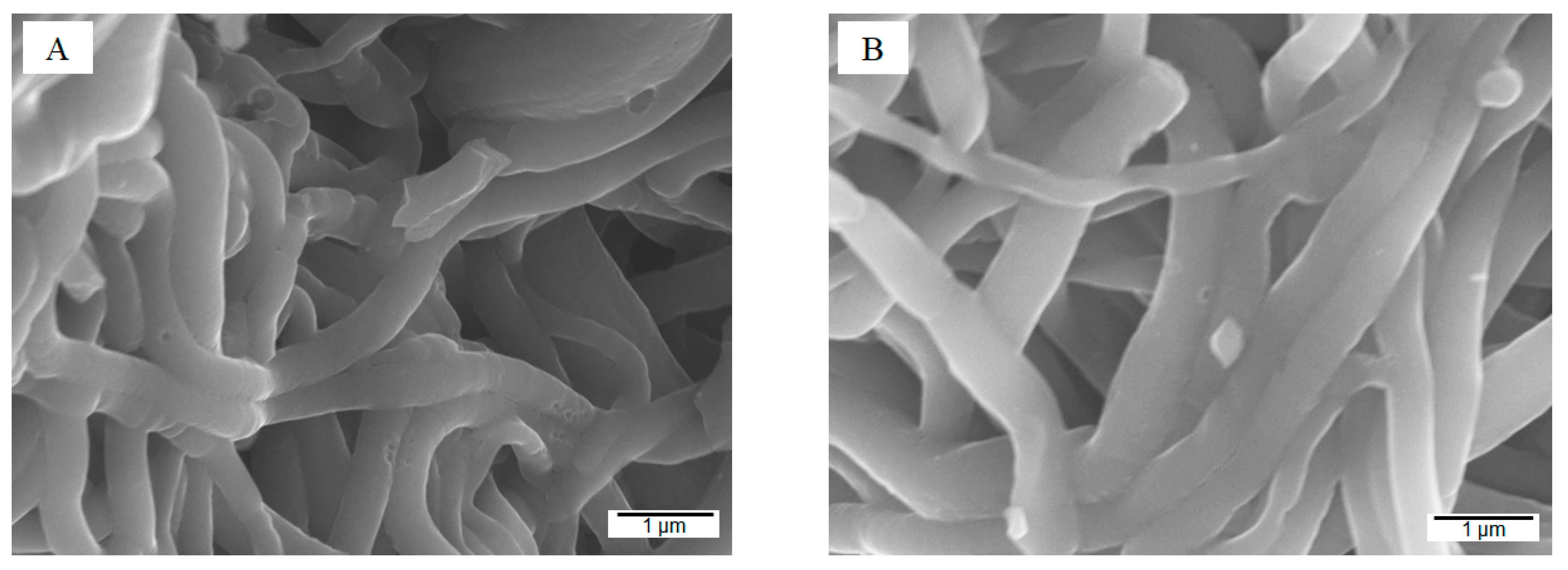
2.1.1. Morphology
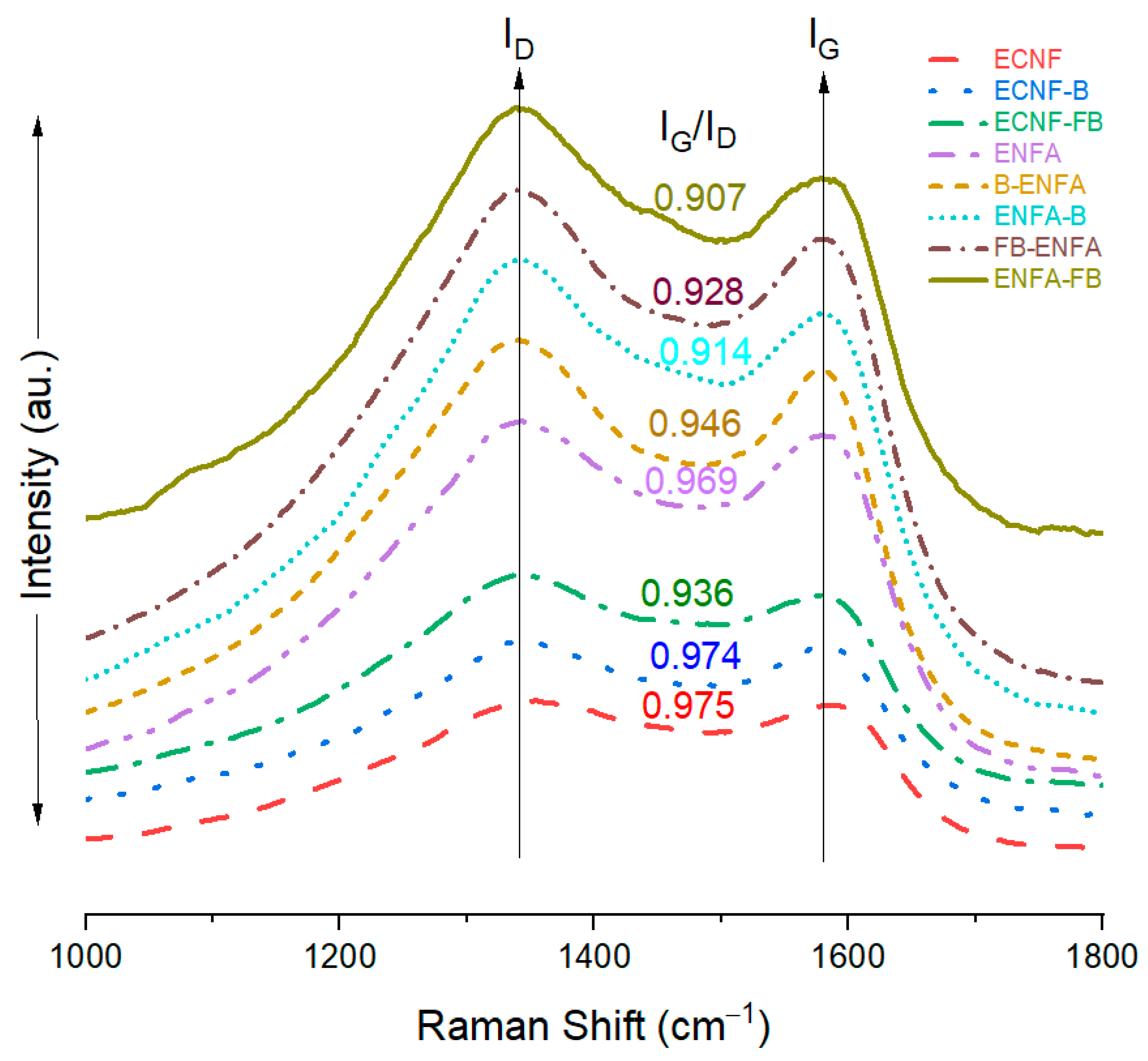
2.1.2. Structure
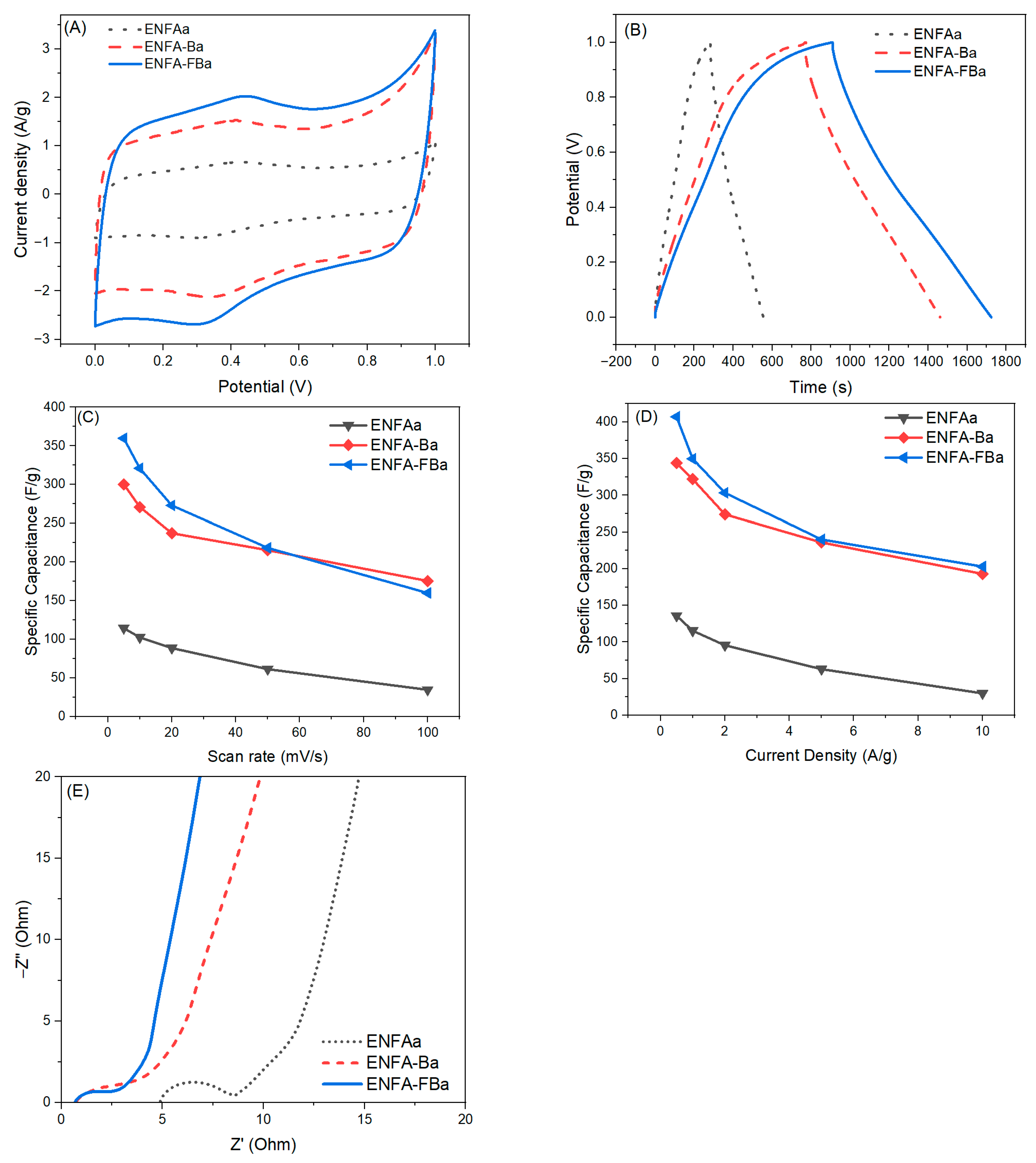
2.1.3. Electrochemical Performance
2.2. Electrode Materials from Activated Aerogels
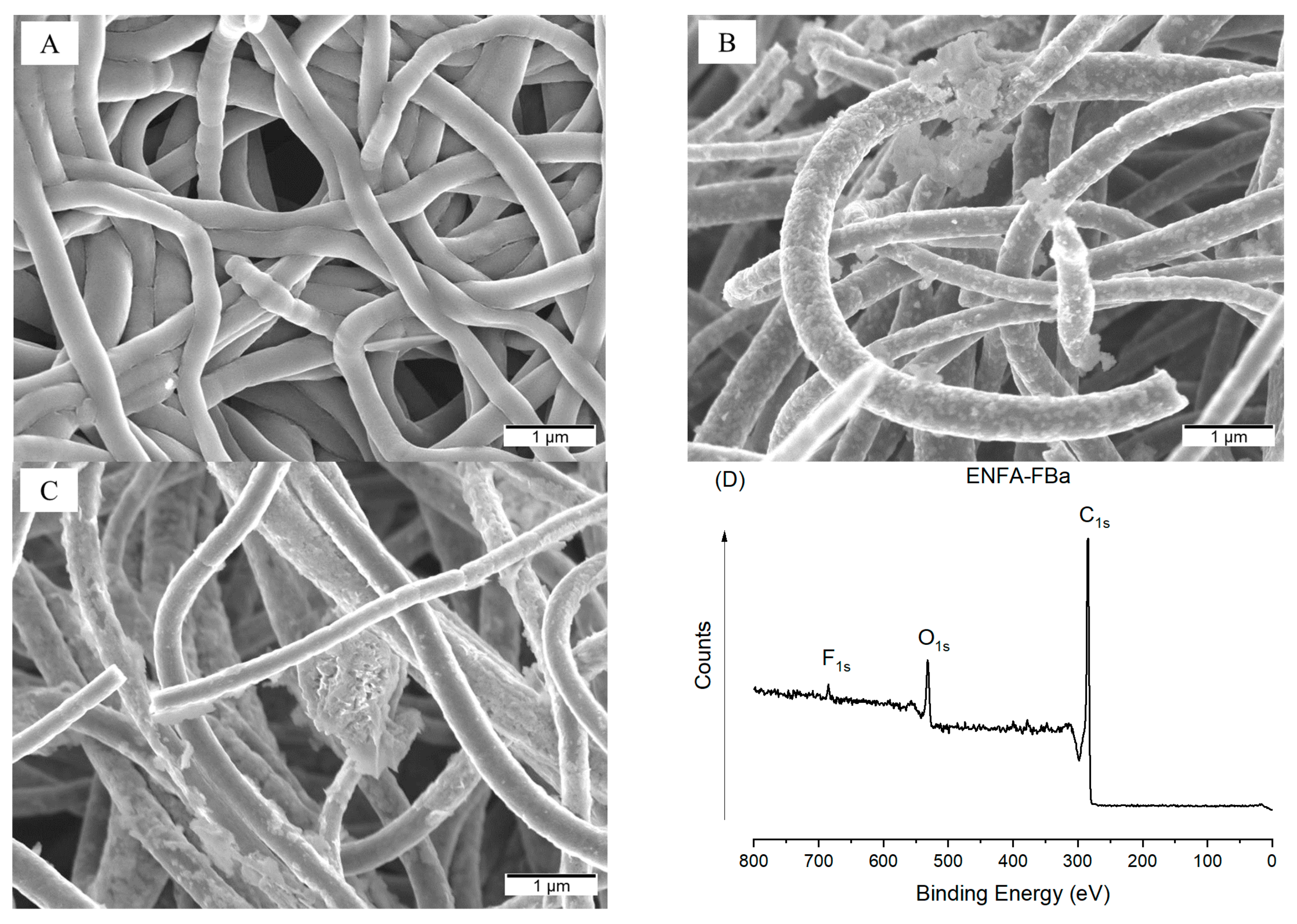
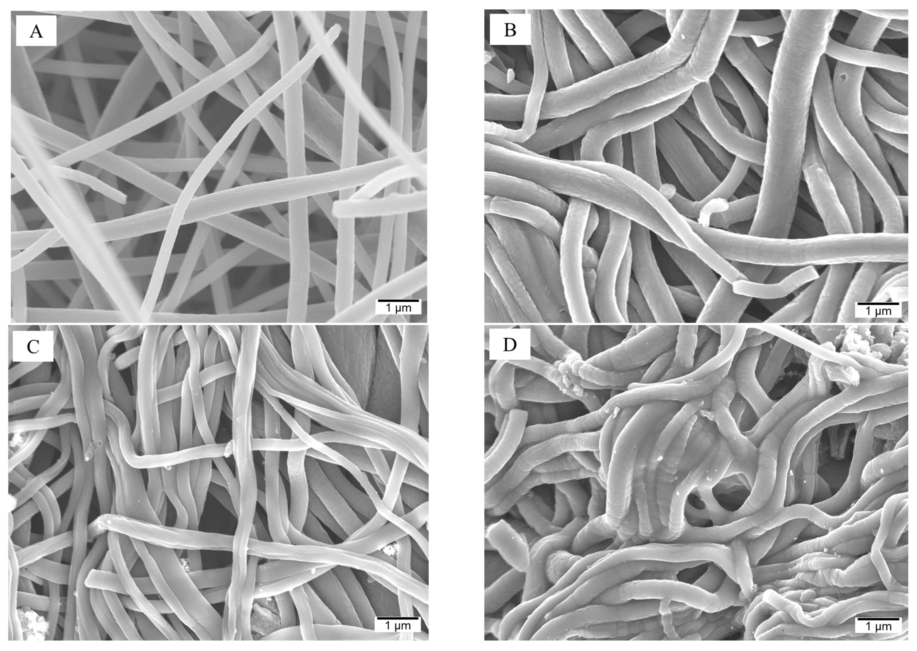
2.2.1. Morphology
2.2.2. Structure
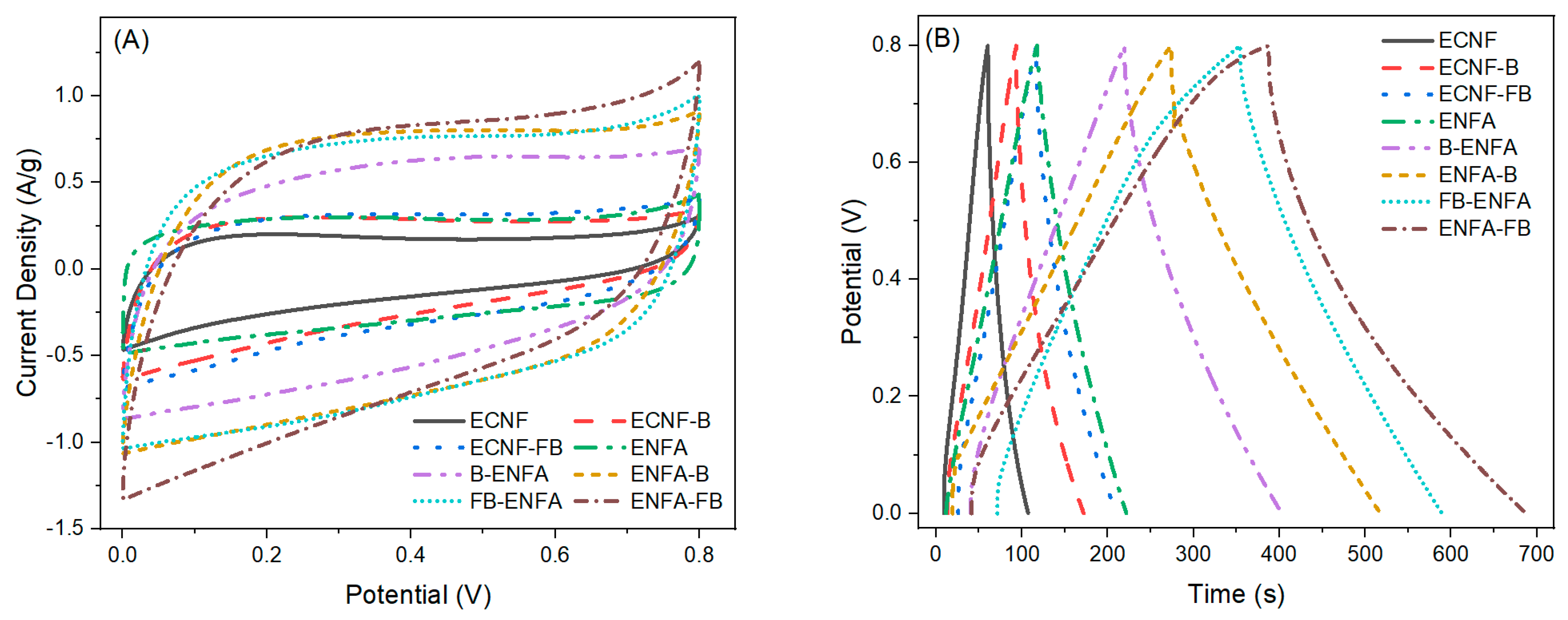
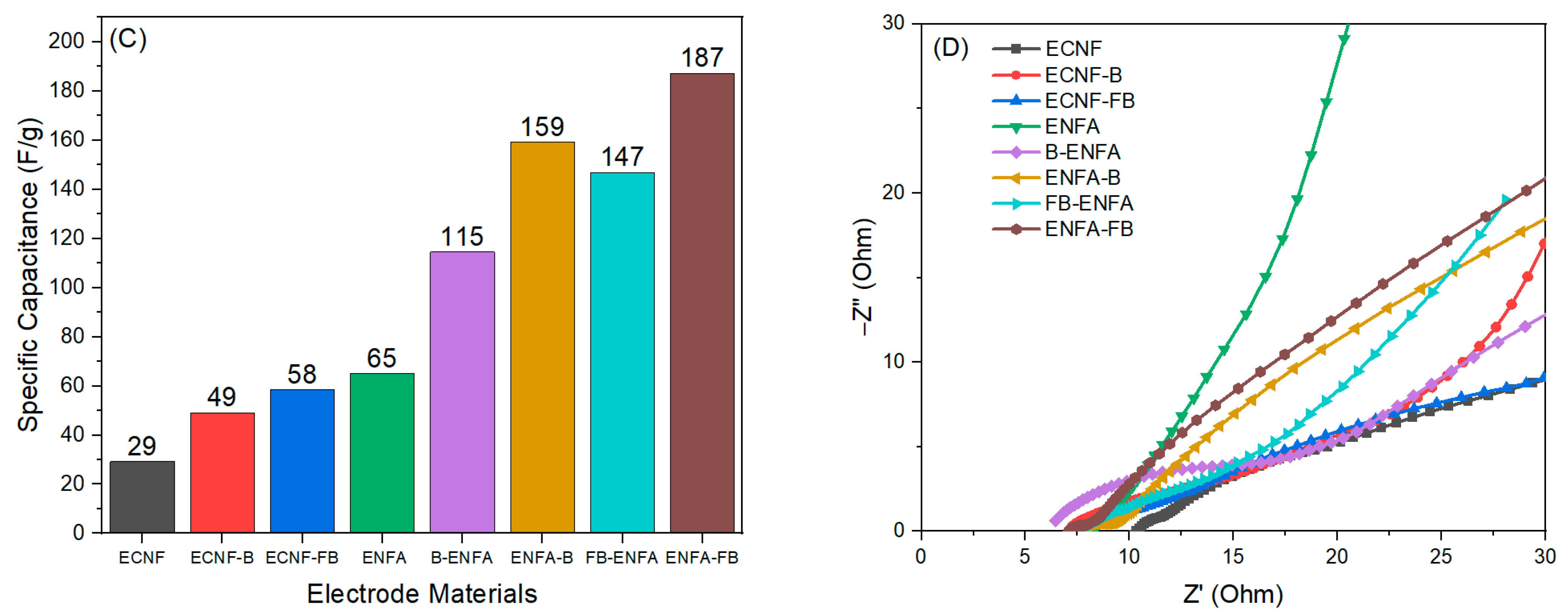
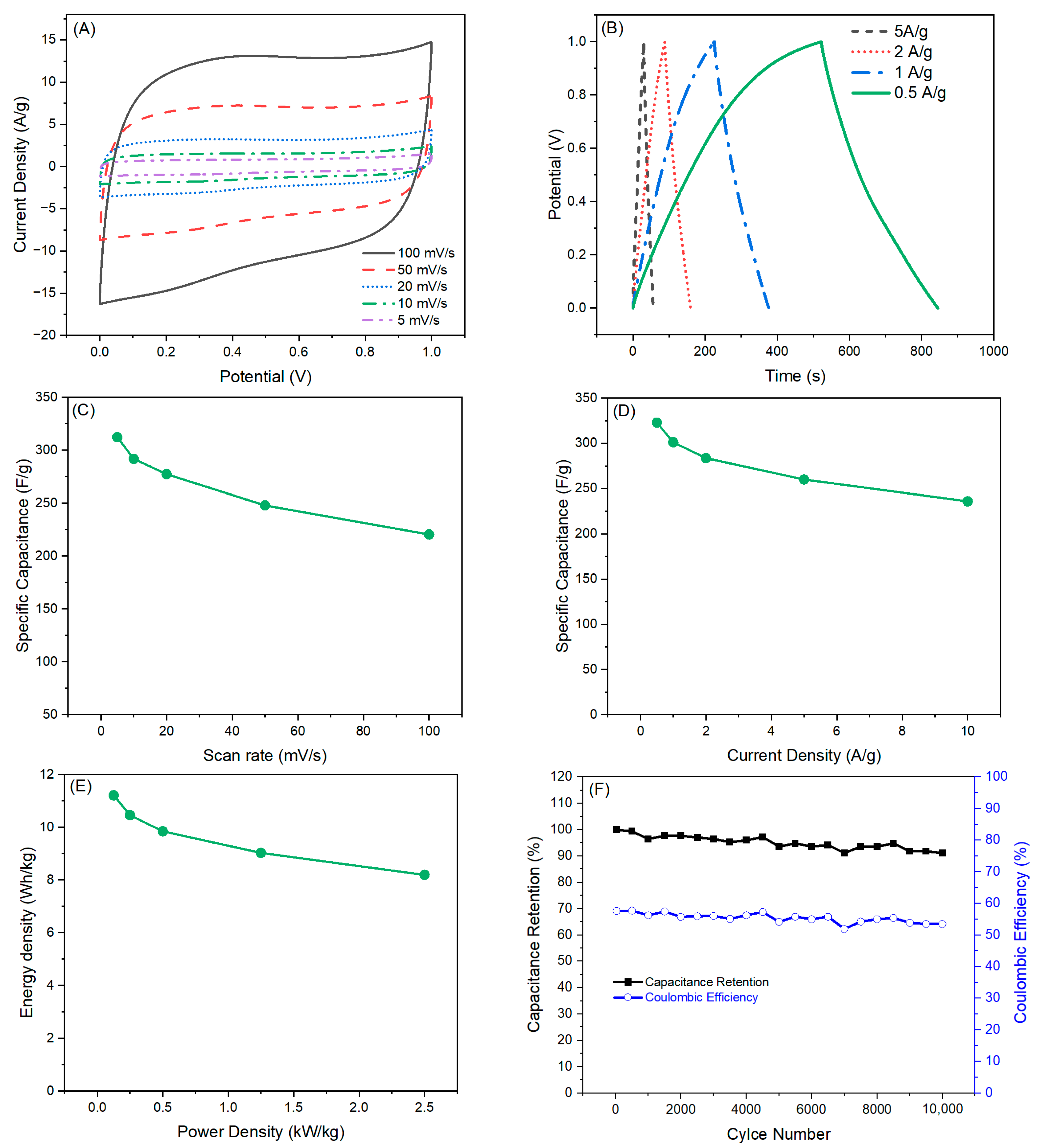
2.2.3. Electrochemical Performance
Three-Electrode Analysis
Two-Electrode Analysis
3. Conclusions
4. Materials and Methods
4.1. Materials
4.2. Biochar Processing
4.3. Electrospinning and Carbonization
4.4. Preparation of Carbon Nanofibrous Aerogels
4.5. Activation of the Carbon Nanofibrous Aerogels
4.6. Characterization
Author Contributions
Funding
Institutional Review Board Statement
Informed Consent Statement
Data Availability Statement
Acknowledgments
Conflicts of Interest
References
- Yu, Z.; Tetard, L.; Zhai, L.; Thomas, J. Supercapacitor electrode materials: Nanostructures from 0 to 3 dimensions. Energy Environ. Sci. 2015, 8, 702–730. [Google Scholar] [CrossRef]
- Raza, W.; Ali, F.; Raza, N.; Luo, Y.; Kim, K.-H.; Yang, J.; Kumar, S.; Mehmood, A.; Kwon, E.E. Recent advancements in supercapacitor technology. Nano Energy 2018, 52, 441–473. [Google Scholar] [CrossRef]
- Sahin, M.E.; Blaabjerg, F.; Sangwongwanich, A. A comprehensive review on supercapacitor applications and developments. Energies 2022, 15, 674. [Google Scholar] [CrossRef]
- Yan, J.; Wang, Q.; Wei, T.; Fan, Z. Recent advances in design and fabrication of electrochemical supercapacitors with high energy densities. Adv. Energy Mater. 2014, 4, 1300816. [Google Scholar] [CrossRef]
- Xue, J.; Wu, T.; Dai, Y.; Xia, Y. Electrospinning and electrospun nanofibers: Methods, materials, and applications. Chem. Rev. 2019, 119, 5298–5415. [Google Scholar] [CrossRef] [PubMed]
- Nie, G.; Zhao, X.; Luan, Y.; Jiang, J.; Kou, Z.; Wang, J. Key issues facing electrospun carbon nanofibers in energy applications: On-going approaches and challenges. Nanoscale 2020, 12, 13225–13248. [Google Scholar] [CrossRef]
- Wang, T.; Chen, Z.; Gong, W.; Xu, F.; Song, X.; He, X.; Fan, M. Electrospun carbon nanofibers and their applications in serval areas. ACS Omega 2023, 8, 22316–22330. [Google Scholar] [CrossRef]
- Zhang, L.; Aboagye, A.; Kelkar, A.; Lai, C.; Fong, H. A review: Carbon nanofibers from electrospun polyacrylonitrile and their applications. J. Mater. Sci. 2014, 49, 463–480. [Google Scholar] [CrossRef]
- Zhang, B.; Kang, F.; Tarascon, J.M.; Kim, J.-K. Recent advances in electrospun carbon nanofibers and their application in electrochemical energy storage. Prog. Mater. Sci. 2016, 76, 319–380. [Google Scholar] [CrossRef]
- Chhetri, K.; Subedi, S.; Muthurasu, A.; Ko, T.H.; Dahal, B.; Kim, H.Y. A review on nanofiber reinforced aerogels for energy storage and conversion applications. J. Energy Storage 2022, 46, 103927. [Google Scholar] [CrossRef]
- Qin, L.; Yang, D.; Zhang, M.; Zhao, T.; Luo, Z.; Yu, Z.-Z. Superelastic and ultralight electrospun carbon nanofiber/MXene hybrid aerogels with anisotropic microchannels for pressure sensing and energy storage. J. Colloid Interface Sci. 2021, 589, 264–274. [Google Scholar] [CrossRef] [PubMed]
- Hasan, M.F.; Zhang, L. Recent Advances in Aerogel Materials from Electrospun Nanofibers: A Review. Fibers Polym. 2023, 24, 1553–1572. [Google Scholar] [CrossRef]
- Alemán, J.V.; Chadwick, A.V.; He, J.; Hess, M.; Horie, K.; Jones, R.G.; Kratochvíl, P.; Meisel, I.; Mita, I.; Moad, G.; et al. Definitions of terms relating to the structure and processing of sols, gels, networks, and inorganic-organic hybrid materials (IUPAC recommendations 2007). Pure Appl. Chem. 2007, 79, 1801–1829. [Google Scholar] [CrossRef]
- Pierre, A.C.; Pajonk, G.M. Chemistry of Aerogels and Their Applications. Chem. Rev. 2002, 102, 4243–4266. [Google Scholar] [CrossRef]
- Zhou, X.; Liu, B.; Chen, Y.; Guo, L.; Wei, G. Carbon nanofiber-based three-dimensional nanomaterials for energy and environmental applications. Mater. Adv. 2020, 1, 2163–2181. [Google Scholar] [CrossRef]
- Ma, Y.; Liu, Q.; Li, W.; Zheng, Y.; Shi, Q.; Zhou, Z.; Shao, G.; Yang, W.; Chen, D.; Fang, X. Ultralight and robust carbon nanofiber aerogels for advanced energy storage. J. Mater. Chem. A 2021, 9, 900–907. [Google Scholar] [CrossRef]
- Huang, Y.; Lai, F.; Zhang, L.; Lu, H.; Miao, Y.-E.; Liu, T. Elastic carbon aerogels reconstructed from electrospun nanofibers and graphene as three-dimensional networked matrix for efficient energy storage/conversion. Sci. Rep. 2016, 6, 31541. [Google Scholar] [CrossRef]
- Cao, M.; Hu, Y.; Cheng, W.; Huan, S.; Bai, T.; Niu, Z.; Zhao, Y.; Yue, G.; Zhao, Y.; Han, G. Lignin-based multi-scale cellular aerogels assembled from co-electrospun nanofibers for oil/water separation and energy storage. Chem. Eng. J. 2022, 436, 135233. [Google Scholar] [CrossRef]
- Ding, Y.; Wang, T.; Dong, D.; Zhang, Y. Using Biochar and Coal as the Electrode Material for Supercapacitor Applications. Front. Energy Res. 2020, 7, 159. [Google Scholar] [CrossRef]
- Husain, Z.; Raheman, A.S.; Ansari, K.B.; Pandit, A.B.; Khan, M.S.; Qyyum, M.A.; Lam, S.S. Nano-sized mesoporous biochar derived from biomass pyrolysis as electrochemical energy storage supercapacitor. Mater. Sci. Energy Technol. 2022, 5, 99–109. [Google Scholar] [CrossRef]
- Xu, T.; Li, X.; Liang, Z.; Amar, V.S.; Huang, R.; Shende, R.V.; Fong, H. Carbon Nanofibrous Sponge Made from Hydrothermally Generated Biochar and Electrospun Polymer Nanofibers. Adv. Fiber Mater. 2020, 2, 74–84. [Google Scholar] [CrossRef]
- Wan, C.; Li, J. Wood-derived biochar supported polypyrrole nanoparticles as a free-standing supercapacitor electrode. RSC Adv. 2016, 6, 86006–86011. [Google Scholar] [CrossRef]
- Yan, B.; Zheng, J.; Feng, L.; Du, C.; Jian, S.; Yang, W.; Wu, Y.A.; Jiang, S.; He, S.; Chen, W. Wood-derived biochar as thick electrodes for high-rate performance supercapacitors. Biochar 2022, 4, 50. [Google Scholar] [CrossRef]
- Wang, T.; Zang, X.; Wang, X.; Gu, X.; Shao, Q.; Cao, N. Recent advances in fluorine-doped/fluorinated carbon-based materials for supercapacitors. Energy Storage Mater. 2020, 30, 367–384. [Google Scholar] [CrossRef]
- Zheng, J.; Lin, Y.; Du, C.; Chen, X.; Li, J.; Zheng, Y.; Feng, Q.; Huang, Z. Fluorine-doped MnO@fluorographene with high conductivity for improved capacity and prolonged cycling stability of lithium-ion anode. J. Alloys Compd. 2023, 945, 169255. [Google Scholar] [CrossRef]
- Lee, H.-M.; Kang, H.-R.; An, K.-H.; Kim, H.-G.; Kim, B.-J. Comparative studies of porous carbon nanofibers by various activation methods. Carbon Lett. 2013, 14, 180–185. [Google Scholar] [CrossRef]
- Ma, C.; Wang, R.; Xie, Z.; Zhang, H.; Li, Z.; Shi, J. Preparation and molten salt-assisted KOH activation of porous carbon nanofibers for use as supercapacitor electrodes. J. Porous Mater. 2017, 24, 1437–1445. [Google Scholar] [CrossRef]
- Wei, L.; Sevilla, M.; Fuertes, A.B.; Mokaya, R.; Yushin, G. Polypyrrole-Derived Activated Carbons for High-Performance Electrical Double-Layer Capacitors with Ionic Liquid Electrolyte. Adv. Funct. Mater. 2012, 22, 827–834. [Google Scholar] [CrossRef]
- Mohammadi, M.A.; Tabar, F.A.; Mohammadpour-Haratbar, A.; Bazargan, A.M.; Mazinani, S.; Keihan, A.H.; Sharif, F. Preparation and evaluation of electrospun carbon nanofibers infused by metal nanoparticles for supercapacitor electrodes application. Synth. Met. 2021, 274, 116706. [Google Scholar] [CrossRef]
- Li, Z.; Deng, L.; Kinloch, I.A.; Young, R.J. Raman spectroscopy of carbon materials and their composites: Graphene, nanotubes and fibres. Prog. Mater. Sci. 2023, 135, 101089. [Google Scholar] [CrossRef]
- Asare, K.; Hasan, M.F.; Shahbazi, A.; Zhang, L. A comparative study of porous and hollow carbon nanofibrous structures from electrospinning for supercapacitor electrode material development. Surf. Interfaces 2021, 26, 101386. [Google Scholar] [CrossRef]
- Na, W.; Jun, J.; Park, J.W.; Lee, G.; Jang, J. Highly porous carbon nanofibers co-doped with fluorine and nitrogen for outstanding supercapacitor performance. J. Mater. Chem. A 2017, 5, 17379–17387. [Google Scholar] [CrossRef]
- Hasan, M.F.; Mantripragada, S.; Gbewonyo, S.; Xiu, S.; Shahbazi, A.; Zhang, L. Carbon nanofibrous electrode material from electrospinning of chlorella (microalgae) with polyacrylonitrile for practical high-performance supercapacitor. Int. J. Energy Res. 2022, 46, 22867–22882. [Google Scholar] [CrossRef]
- Lv, Y.; Zhang, F.; Dou, Y.; Zhai, Y.; Wang, J.; Liu, H.; Xia, Y.; Tu, B.; Zhao, D. A comprehensive study on KOH activation of ordered mesoporous carbons and their supercapacitor application. J. Mater. Chem. 2012, 22, 93–99. [Google Scholar] [CrossRef]
- Yang, Y.; Liu, Y.-X.; Li, Y.; Deng, B.-W.; Yin, B.; Yang, M.-B. Design of compressible and elastic N-doped porous carbon nanofiber aerogels as binder-free supercapacitor electrodes. J. Mater. Chem. A 2020, 8, 17257–17265. [Google Scholar] [CrossRef]
- Esarev, I.V.; Agafonov, D.V.; Surovikin, Y.V.; Nesov, S.N.; Lavrenov, A.V. On the cause of non-linearity of galvanostatic charge curves of electrical double layer capacitors. Electrochim. Acta 2021, 390, 138896. [Google Scholar] [CrossRef]


| Sample Name | BET Surface Area | Average Pore Size | Vmic | Vmes | Vmac | Vt | %Vmic | %Vmes | %Vmac |
|---|---|---|---|---|---|---|---|---|---|
| m2/g | nm | cm3/g | cm3/g | cm3/g | cm3/g | % | % | % | |
| ECNF | 13.8 | 14.9 | 0.0011 | 0.0135 | 0.0149 | 0.02951 | 3.8 | 45.82 | 50.38 |
| ECNF-B | 50.4 | 15.5 | 0.003 | 0.0927 | 0.0684 | 0.1641 | 1.83 | 56.49 | 41.67 |
| ECNF-FB | 63.1 | 10.1 | 0.0035 | 0.0408 | 0.0253 | 0.06963 | 5.01 | 58.61 | 36.38 |
| ENFA | 229 | 7.8 | 0.01 | 0.0225 | 0.0346 | 0.06722 | 14.97 | 33.50 | 51.53 |
| B-ENFA | 309 | 5.0 | 0.0089 | 0.0175 | 0.0168 | 0.04322 | 20.63 | 40.55 | 38.82 |
| ENFA-B | 435 | 5.1 | 0.0132 | 0.0812 | 0.0067 | 0.1012 | 13.07 | 80.33 | 6.60 |
| FB-ENFA | 417 | 4.4 | 0.0185 | 0.0935 | 0.0163 | 0.1284 | 14.44 | 72.85 | 12.71 |
| ENFA-FB | 472 | 5.8 | 0.0167 | 0.1085 | 0.0352 | 0.1605 | 10.38 | 67.66 | 21.95 |
| Sample Name | BET Surface Area | Average Pore Size | Vmic | Vmes | Vmac | Vt | %Vmic | %Vmes | %Vmac |
|---|---|---|---|---|---|---|---|---|---|
| m2/g | nm | cm3/g | cm3/g | cm3/g | cm3/g | % | % | % | |
| ENFAa | 1137 | 2.5 | 0.1155 | 0.0521 | 0.0243 | 0.1919 | 60.18 | 27.13 | 12.69 |
| ENFA-Ba | 1319 | 2.3 | 0.3113 | 0.2513 | 0.0331 | 0.5957 | 52.25 | 42.19 | 5.56 |
| ENFA-FBa | 1375 | 2.3 | 0.3262 | 0.3719 | 0.0367 | 0.7348 | 44.39 | 50.61 | 5.0 |
Disclaimer/Publisher’s Note: The statements, opinions and data contained in all publications are solely those of the individual author(s) and contributor(s) and not of MDPI and/or the editor(s). MDPI and/or the editor(s) disclaim responsibility for any injury to people or property resulting from any ideas, methods, instructions or products referred to in the content. |
© 2024 by the authors. Licensee MDPI, Basel, Switzerland. This article is an open access article distributed under the terms and conditions of the Creative Commons Attribution (CC BY) license (https://creativecommons.org/licenses/by/4.0/).
Share and Cite
Hasan, M.F.; Asare, K.; Mantripragada, S.; Charles, V.; Shahbazi, A.; Zhang, L. Meso-Microporous Carbon Nanofibrous Aerogel Electrode Material with Fluorine-Treated Wood Biochar for High-Performance Supercapacitor. Gels 2024, 10, 82. https://doi.org/10.3390/gels10010082
Hasan MF, Asare K, Mantripragada S, Charles V, Shahbazi A, Zhang L. Meso-Microporous Carbon Nanofibrous Aerogel Electrode Material with Fluorine-Treated Wood Biochar for High-Performance Supercapacitor. Gels. 2024; 10(1):82. https://doi.org/10.3390/gels10010082
Chicago/Turabian StyleHasan, Md Faruque, Kingsford Asare, Shobha Mantripragada, Victor Charles, Abolghasem Shahbazi, and Lifeng Zhang. 2024. "Meso-Microporous Carbon Nanofibrous Aerogel Electrode Material with Fluorine-Treated Wood Biochar for High-Performance Supercapacitor" Gels 10, no. 1: 82. https://doi.org/10.3390/gels10010082
APA StyleHasan, M. F., Asare, K., Mantripragada, S., Charles, V., Shahbazi, A., & Zhang, L. (2024). Meso-Microporous Carbon Nanofibrous Aerogel Electrode Material with Fluorine-Treated Wood Biochar for High-Performance Supercapacitor. Gels, 10(1), 82. https://doi.org/10.3390/gels10010082