Kinking and Torsion Can Significantly Improve the Efficiency of Valveless Pumping in Periodically Compressed Tubular Conduits. Implications for Understanding of the Form-Function Relationship of Embryonic Heart Tubes


Abstract
:1. Introduction
2. Materials and Methods
2.1. Liebau-Effect Pumps
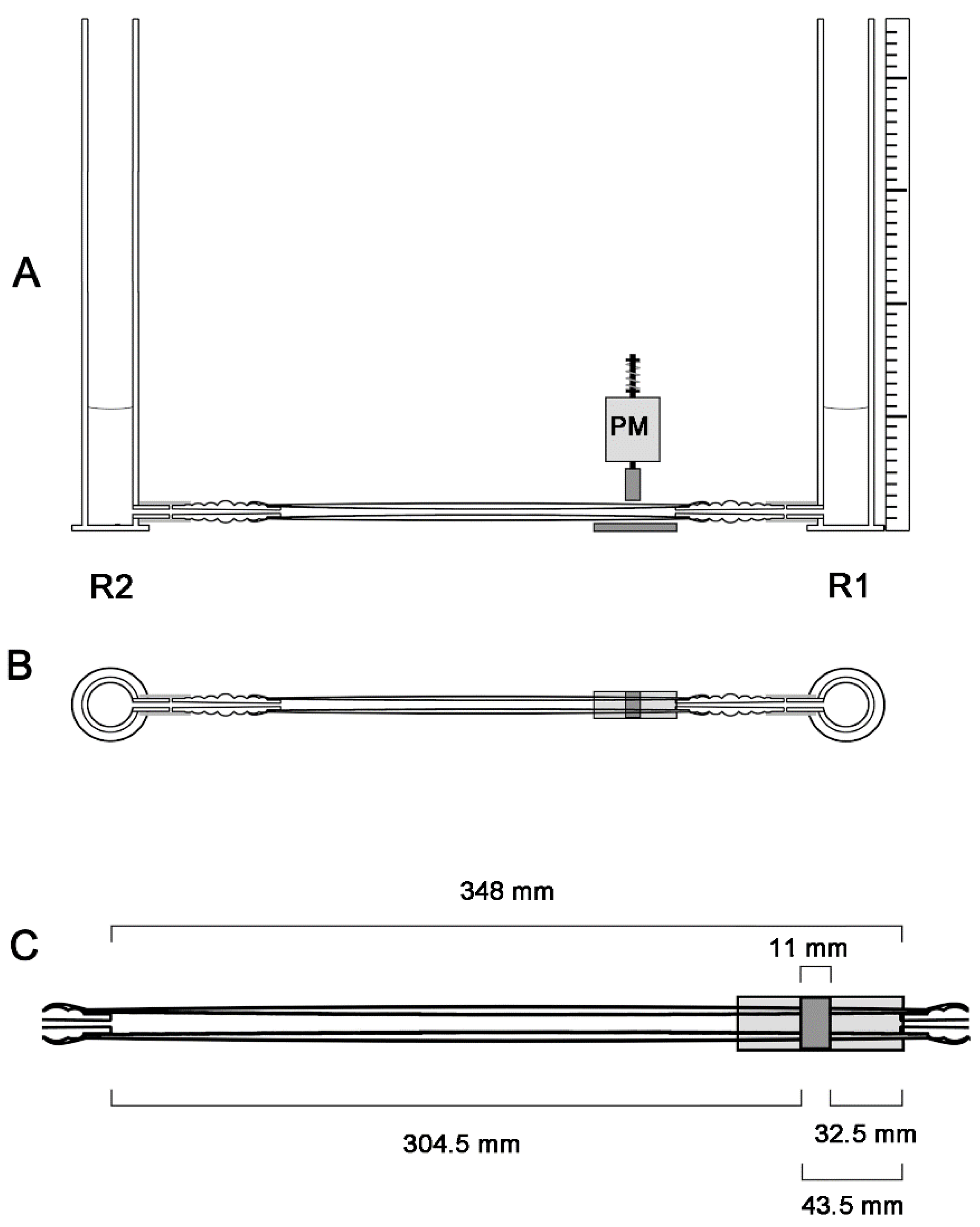
2.2. General Design of the Experimental Apparatus
2.3. Pinching Machine and Modes of Periodic Compression
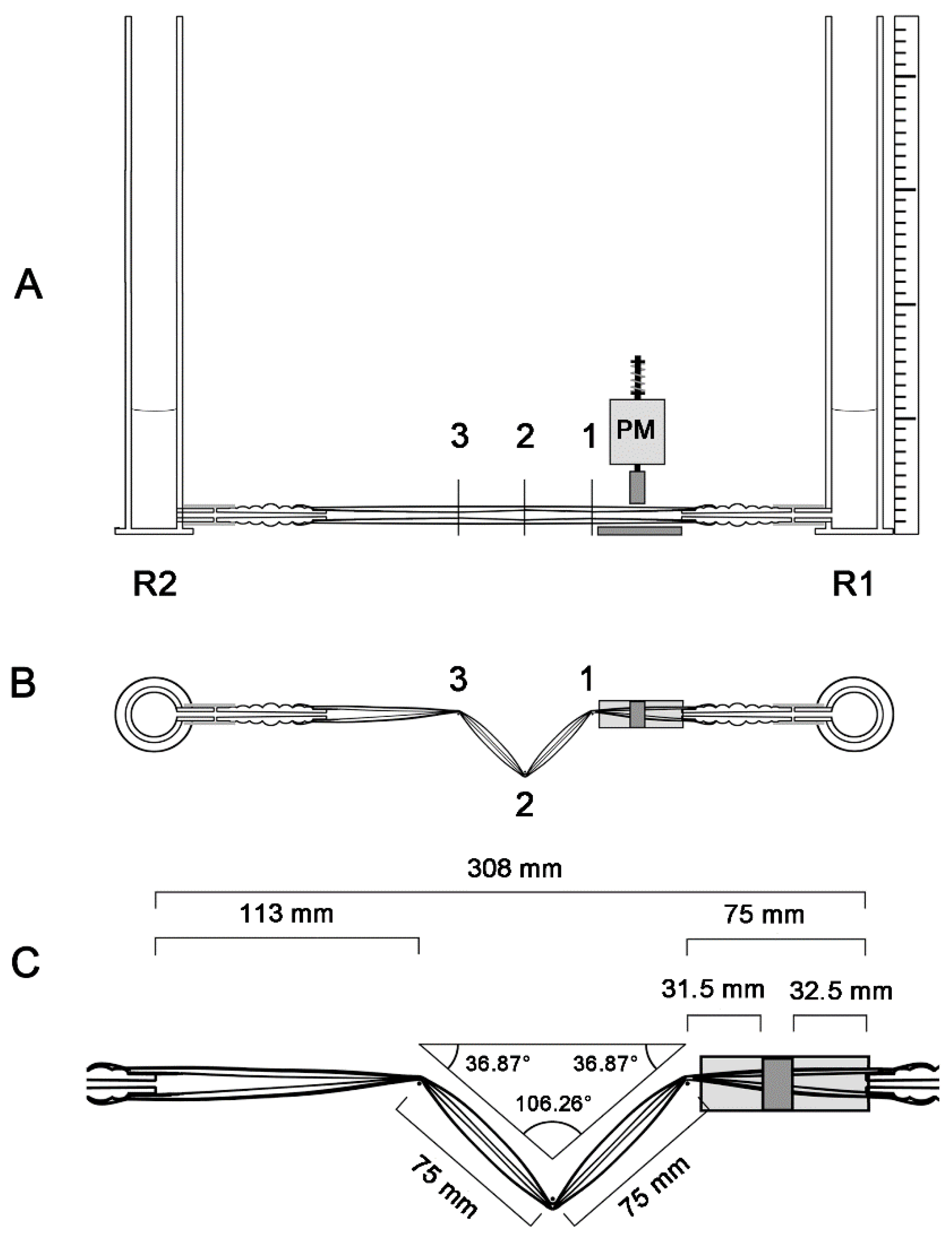
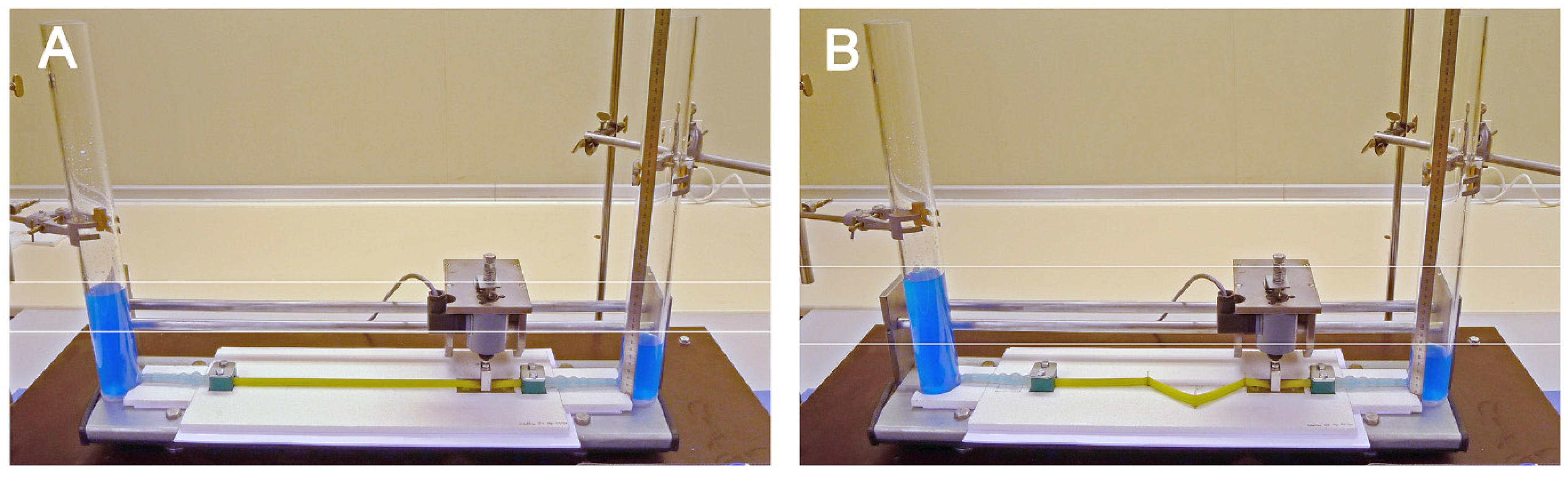
2.4. Geometric Configurations of the Liebau-Effect Pump
2.5. Measurements and Calculations
3. Results and Discussion
3.1. Minimum Compression Rate Needed for Generation of Unidirectional Net Flow
3.2. Relation between Compression Frequencies and Stability of Flow Direction
3.3. Relation between Flow Direction and Position of the Compression Zone
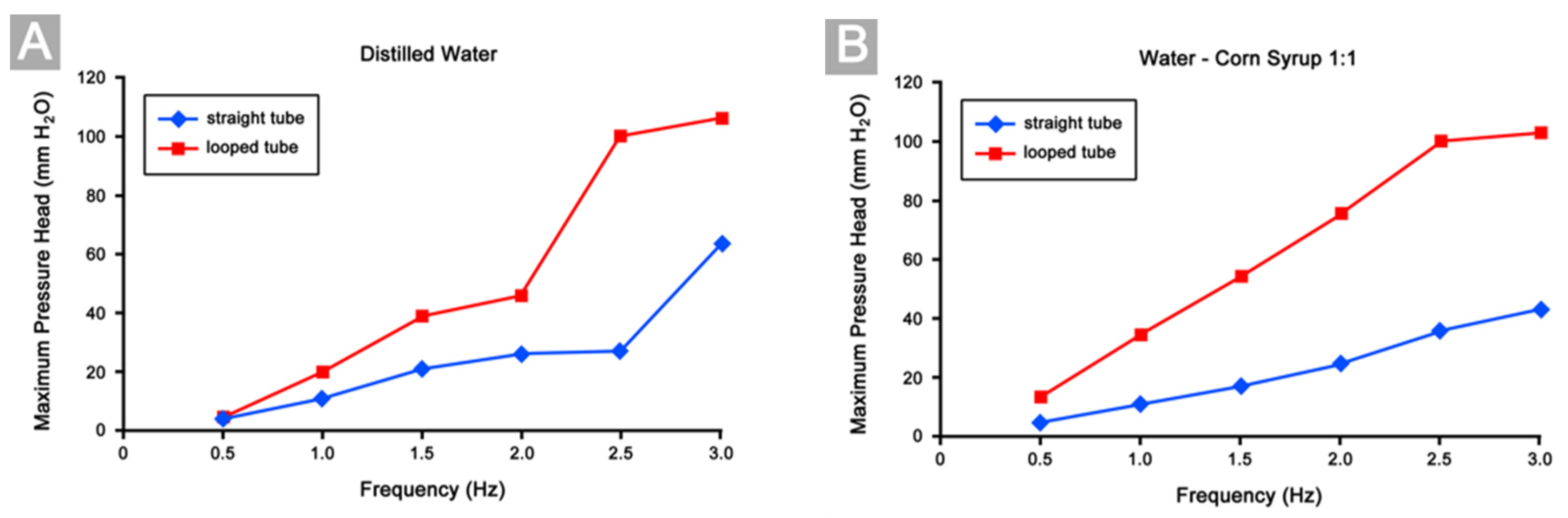
3.4. Differences in Pumping Performance
3.5. Mechanisms Responsible for Improvement of Pumping Efficiency
3.6. Biological Relevance
3.7. Technical Relevance
Acknowledgments
Author Contributions
Conflicts of Interest
References
- Vogel, S. Life in Moving Fluids: The Physical Biology of Flow, 2nd ed.; Princeton University Press: Princeton, NJ, USA, 1994; ISBN 0-691-03485-0. [Google Scholar]
- Vogel, S. Living in a physical world. X. Pumping fluids through conduits. J. Biosci. 2007, 32, 207–222. [Google Scholar] [CrossRef] [PubMed]
- Bazigou, E.; Makinen, T. Flow control in our vessels: Vascular valves make sure there is no way back. Cell. Mol. Life Sci. 2013, 70, 1055–1066. [Google Scholar] [CrossRef] [PubMed]
- Jaffrin, M.Y.; Shapiro, A.H. Peristaltic pumping. Annu. Rev. Fluid Mech. 1971, 3, 13–37. [Google Scholar] [CrossRef]
- Liebau, G. Über ein Ventilloses Pumpprinzip. Naturwissenschaften 1954, 41, 327. [Google Scholar] [CrossRef]
- Liebau, G. Über physiologische Grundlagen klappenloser Blutförderung. Verh. Dtsch. Ges. Kreislaufforsch. 1968, 34, 293–296. [Google Scholar] [PubMed]
- Männer, J.; Wessel, A.; Yelbuz, T.M. How does the tubular embryonic heart work? Looking for the physical mechanism driving unidirectional blood flow in the valveless embryonic heart tube. Dev. Dyn. 2010, 239, 1035–1046. [Google Scholar] [CrossRef] [PubMed]
- Liebau, G. Herzpulsation und Blutbewegung. Z. Gesamte Med. 1955, 125, 482–489. [Google Scholar] [CrossRef]
- Liebau, G. Die Strömungsprinzipien des Herzens. Z. Kreislaufforsch. 1955, 44, 677–684. [Google Scholar] [PubMed]
- Liebau, G. Über periphere Blutförderung. In Phänomen der Pulsierenden Strömung im Blutkreislauf aus Technologischer, Physiologischer und Klinischer Sicht; Pestel, E., Liebau, G., Eds.; Bibliograph Institut: Mannheim, Germany, 1970; pp. 67–78. [Google Scholar]
- Moser, M.; Huang, J.W.; Schwarz, G.S.; Kenner, T.; Noordergraaf, A. Impedance defined flow. Generalisation of William Harvey’s concept of the circulation—370 years later. Int. J. Cardiovasc. Med. Sci. 1998, 1, 205–211. [Google Scholar]
- Pahlevan, N.M.; Gharib, M. In vitro investigation of a potential wave pumping effect in human aorta. J. Biomech. 2013, 46, 2122–2129. [Google Scholar] [CrossRef] [PubMed]
- Britten, S.; Soenksen, D.M.; Bustillo, M.; Coulam, C.B. Very early (24–56 days from the last menstrual period) embryonic heart rate in normal pregnancies. Hum. Reprod. 1994, 9, 2424–2426. [Google Scholar] [CrossRef] [PubMed]
- Wisser, J.; Dirschedl, P. Embryonic heart rate in dated human embryos. Early Hum. Dev. 1994, 37, 107–115. [Google Scholar] [CrossRef]
- Moorman, A.F.M.; Christoffels, V.M. Cardiac chamber formation: Development, genes, and evolution. Physiol. Rev. 2003, 83, 1223–1267. [Google Scholar] [CrossRef] [PubMed]
- Bischoff, T.L.W. Entwickelungsgeschichte des Säugethier-und Menscheneies; Verlag L. Voß: Leipzig, Germany, 1842. [Google Scholar]
- Fischel, A. Die Entwicklung des Herzens. In Lehrbuch der Entwicklungsgeschichte des Menschen; Fischel, A., Ed.; Springer: Berlin, Germany, 1929; pp. 677–702. [Google Scholar]
- Sperelakis, N. Pacemaker mechanisms in myocardial cells during development of embryonic chick hearts. Dev. Cardiovasc. Med. 1982, 17, 129–165. [Google Scholar]
- Xavier-Neto, J.; Castro, R.A.; Sampaio, A.C.; Azambuja, A.P.; Castillo, H.A.; Cravo, R.M.; Simões-Costa, M.S. Parallel avenues in the evolution of hearts and pumping organs. Cell. Mol. Life Sci. 2007, 64, 719–734. [Google Scholar] [CrossRef] [PubMed]
- Forouhar, A.S.; Liebling, M.; Hickerson, A.; Nasiraei-Moghaddam, A.; Tsai, H.J.; Hove, J.R.; Fraser, S.E.; Dickinson, M.E.; Gharib, M. The embryonic vertebrate heart tube is a dynamic suction pump. Science 2006, 312, 751–753. [Google Scholar] [CrossRef] [PubMed]
- Taber, L.A.; Zhang, J.; Perucchio, R. Computational model for the transition from peristaltic to pulsatile flow in the embryonic heart tube. J. Biomech. Eng. 2007, 129, 441–449. [Google Scholar] [CrossRef] [PubMed]
- Maes, F.; Chaudry, B.; Van Ransbeek, P.; Verdonck, P. The pumping mechanism of embryonic hearts. IFMBE Proc. 2011, 37, 470–473. [Google Scholar]
- Santhanakrishnan, A.; Miller, L.A. Fluid dynamics of heart development. Cell. Biochem. Biophys. 2011, 61, 1–22. [Google Scholar] [CrossRef] [PubMed]
- Baird, A.; King, T.; Miller, L.A. Numerical study of scaling effects in peristalsis and dynamic suction pumping. In Proceedings of the AMS, Special Session on Biological Fluid Dynamics: Modeling, Computations, and Applications, New Orleans, LA, USA, 13 October 2012; Volume 628, pp. 129–148. [Google Scholar]
- Baird, A.; Waldrop, L.; Miller, L.A. Neuromechanical pumping: Boundary flexibility and traveling depolarization waves drive flow within valveless, tubular hearts. Jpn. J. Ind. Appl. Math. 2015, 32, 829–846. [Google Scholar] [CrossRef]
- Boselli, F.; Freund, J.B.; Vermot, J. Blood flow mechanics in cardiovascular development. Cell. Mol. Life Sci. 2015, 72, 2545–2559. [Google Scholar] [CrossRef] [PubMed]
- Kozlovsky, P.; Rosenfeld, M.; Jaffa, A.J.; Elad, D. Dimensionless analysis of valveless pumping in a thick-wall elastic tube: Application to the tubular embryonic heart. J. Biomech. 2015, 48, 1652–1661. [Google Scholar] [CrossRef] [PubMed]
- Kozlovsky, P.; Bryson-Richardson, R.J.; Jaffa, A.J.; Rosenfeld, M.; Elad, D. The driving mechanism for unidirectional blood flow in the tubular embryonic heart. Ann. Biomed. Eng. 2016, 44, 3069–3083. [Google Scholar] [CrossRef] [PubMed]
- Waldrop, L.; Miller, L. Large-amplitude, short wave peristalsis and its implications for transport. Biomech. Model. Mechanobiol. 2016, 15, 629–642. [Google Scholar] [CrossRef] [PubMed]
- Männer, J. The anatomy of cardiac looping: A step towards the understanding of the morphogenesis of several forms of congenital cardiac malformations. Clin. Anat. 2009, 22, 21–35. [Google Scholar] [CrossRef] [PubMed]
- Bayraktar, M.; Männer, J. Cardiac looping may be driven by compressive loads resulting from unequal growth of the heart and pericardial cavity. Observations on a physical simulation model. Front. Physiol. 2014, 5, 112. [Google Scholar] [CrossRef] [PubMed]
- Patten, B.M. The formation of the cardiac loop in the chick. Am. J. Anat. 1922, 30, 373–397. [Google Scholar] [CrossRef]
- Männer, J. Cardiac looping in the chick embryo: A morphological review with special reference to terminological and biomechanical aspects of the looping process. Anat. Rec. 2000, 259, 248–262. [Google Scholar] [CrossRef]
- Goette, A. Die Entwicklungsgeschichte der Unke (Bombinator Igneus). Als Grundlage einer Vergleichenden Morphologie der Wirbelthiere; Voss: Leipzig, Germany, 1875. [Google Scholar]
- Davis, C.L. The development of the human heart from its first appearance to the stage found in embryos of twenty paired somites. Contrib. Embryol. Carnegie Inst. 1927, 19, 245–284. [Google Scholar]
- Bremer, J.L. Part I. An interpretation of the development of the heart. Part II. The left aorta of reptiles. Am. J. Anat. 1928, 42, 307–369. [Google Scholar] [CrossRef]
- Tschermak, A. Über das Verhalten des embryonalen Fischherzens gegenüber dem konstanten Strom. Z. Exp. Med. 1929, 68, 452–474. [Google Scholar] [CrossRef]
- Grant, R.P. The morphogenesis of corrected transposition and other anomalies of cardiac polarity. Circulation 1964, 29, 71–83. [Google Scholar] [CrossRef] [PubMed]
- Männer, J. On the form problem of embryonic heart loops, its geometrical solutions, and a new biophysical concept of cardiac looping. Ann. Anat. 2013, 195, 312–323. [Google Scholar] [CrossRef] [PubMed]
- Weibel, J.; Fields, W.S. Tortuosity, kinking and coiling of the carotid artery. Neurology 1965, 15, 7–14. [Google Scholar] [CrossRef] [PubMed]
- Han, H.C.; Chesnutt, J.K.W.; Garcia, J.R.; Liu, Q.; Wen, Q. Artery buckling: New phenotypes, models, and applications. Ann. Biomed. Eng. 2012. [Google Scholar] [CrossRef] [PubMed]
- Leipzig, T.J.; Dohrmann, G.J. The tortuous or kinked carotid artery: Pathogenesis and clinical considerations. Surg. Neurol. 1986, 25, 478–486. [Google Scholar] [CrossRef]
- Togay-Isikay, C.; Kim, J.; Betterman, K.; Andrews, C.; Meads, D.; Tesh, P.; Tegeler, C.; Öztuna, D. Carotid artery tortuosity, kinking, coiling: Stroke risk factor, marker, or curiosity. Acta Neurol. Belg. 2005, 105, 68–72. [Google Scholar] [PubMed]
- Metz, H.; Murray-Leslie, R.M.; Bannister, R.G.; Bull, J.W.D.; Marshall, J. Kinking of the internal carotid artery in relation to cerebrovascular disease. Lancet 1961, 25, 424–426. [Google Scholar] [CrossRef]
- Schep, G.; Bender, M.H.M.; Schmikli, S.L.; Wijn, P.F.F. Color Doppler used to detect kinking and intravascular lesions in the iliac arteries in endurance athlets with claudication. Eur. J. Ultrasound 2001, 14, 129–140. [Google Scholar] [CrossRef]
- Serraf, A.; Bruniaux, J.; Lacour Gayet, F.; Sidi, D.; Kachaner, J.; Bouchart, F.; Planche, C. Anatomic correction of transposition of the great arteries with ventricular septal defect. Experience with 118 cases. J. Thorac. Cardiovasc. Surg. 1991, 102, 140–147. [Google Scholar] [PubMed]
- Taylor, A.J.; Byers, J.P.; Cheitlin, M.D.; Virmani, R. Anomalous right or left coronary artery from the contralateral coronary sinus: “High-risk” abnormalities in the initial coronary artery course and heterogeneous clinical outcomes. Am. Heart J. 1997, 133, 428–435. [Google Scholar] [CrossRef]
- Derrick, J.R.; Estess, M.; Williams, D. Circulatory dynamics in kinking of the carotid artery. Surgery 1965, 58, 381–383. [Google Scholar] [PubMed]
- Endean, E.D.; DeJong, S.; Dobrin, P.B. Effect of twist on flow and patency of vein grafts. J. Vasc. Surg. 1988, 9, 651–655. [Google Scholar] [CrossRef]
- Fischer, V.W.; Siddiqi, A.; Yusfaly, Y. Altered angioarchitecture in selected areas of brains with Alzheimer’s disease. Acta Neuropathol. 1990, 79, 672–679. [Google Scholar] [CrossRef] [PubMed]
- De la Torre, J.C. Hemodynamic consequences of deformed microvessels in the brain in Alzheimer’s disease. Ann. N. Y. Acad. Sci. 1997, 826, 75–91. [Google Scholar] [CrossRef] [PubMed]
- Blum, M.; Feistel, K.; Thumberger, T.; Schweickert, A. The evolution and conservation of left-right patterning mechanisms. Development 2014, 141, 1603–1613. [Google Scholar] [CrossRef] [PubMed]
- Clowes, J. The functional diversity of essential genes required for mammalian cardiac development. Genesis 2014, 52, 713–737. [Google Scholar] [CrossRef] [PubMed]
- Pernkopf, E.; Wirtinger, W. Die Transposition der Herzostien—Ein Versuch der Erklärung dieser Erscheinung. I. Teil. Die Pheronomie der Herzentwicklung. Z. Anat. Entwickl. Gesch. 1933, 100, 563–711. [Google Scholar] [CrossRef]
- Meredith, M.A.; Hutchins, G.M.; Moore, G.W. Role of the left interventricular sulcus in formation of the interventricular septum and crista supraventricularis in normal human cardiogenesis. Anat. Rec. 1979, 194, 417–428. [Google Scholar] [CrossRef] [PubMed]
- Kathiriya, I.S.; Srivastava, D. Left-right asymmetry and cardiac looping: Implications for cardiac development and congenital heart disease. Am. J. Med. Genet. 2000, 97, 271–279. [Google Scholar] [CrossRef]
- Kilner, P.J.; Yang, G.Z.; Wilkes, A.J.; Mohladdin, R.H.; Firmin, D.N.; Yacoub, M.H. Asymmetric redirection of flow through the heart. Nature 2000, 404, 759–761. [Google Scholar] [CrossRef] [PubMed]
- Watanabe, H.; Sugiura, S.; Hisada, T. The looped heart does not save energy by maintaining the momentum of flow in the ventricle. Am. J. Physiol. Heart Circ. Physiol. 2008, 294, H2192–H2196. [Google Scholar] [CrossRef] [PubMed]
- Watanabe, H.; Sugiura, S.; Hisada, T. Reply to “Letter to the editor: ‘Postulated functional advantages of a looped as opposed to a linearly arranged heart’”. Am. J. Physiol. Heart Circ. Physiol. 2010, 298, H727. [Google Scholar] [CrossRef]
- Conway, S.J.; Kruzynska-Frejtag, A.; Kneer, P.L.; Machnicki, M.; Koushik, S.V. What cardiovascular defect does my prenatal mouse mutant have, and why? Genesis 2003, 35, 1–21. [Google Scholar] [CrossRef] [PubMed]
- Robertson, J.I. The development of the heart and vascular system of Lepidosiren paradoxa. Q. J. Microsc. Sci. 1914, 59, 53–132. [Google Scholar]
- Mohun, T.J.; Leong, L.M.; Weninger, W.J.; Sparrow, D.B. The morphology of heart development in Xenopus laevis. Dev. Biol. 2000, 218, 47–88. [Google Scholar] [CrossRef] [PubMed]
- Icardo, J.M.; Guerrero, A.; Duran, A.C.; Domezian, A.; Colvee, E.; Sans-Coma, V. The development of the sturgeon heart. Anat. Embryol. 2004, 208, 439–449. [Google Scholar] [CrossRef] [PubMed]
- Simões-Costa, M.S.; Vasconcelos, M.; Sampaio, A.C.; Cravo, R.M.; Linhares, V.L.; Hochgreb, T.; Yan, C.Y.I.; Davidson, B.; Xavier-Neto, J. The evolutionary origin of cardiac chambers. Dev. Biol. 2005, 277, 1–15. [Google Scholar] [CrossRef] [PubMed]
- Stainier, D.Y.R.; Lee, R.K.; Fishman, M.C. Cardiovascular development in the zebrafish. I. Myocardial fate map and heart tube formation. Development 1993, 119, 31–40. [Google Scholar] [PubMed]
- Kilner, P.J. Letter to the editor: “Postulated functional advantages of a looped as opposed to a linearly arranged heart. Am. J. Physiol. Heart Circ. Physiol. 2010, 298, H726. [Google Scholar] [CrossRef] [PubMed]
- Amodeo, A.; Olivero, M.; Versacci, P.; Marino, B. Spiral shapes in hearts and shells: When form and function do matter. Eur. J. Cardio Thorac. Surg. 2012, 41, 473–475. [Google Scholar] [CrossRef] [PubMed]
- Liebling, M.; Forouhar, A.S.; Wolleschensky, R.; Zimmermann, B.; Ankerhold, R.; Fraser, S.E.; Gharib, M.; Dickinson, M.E. Rapid three-dimensional imaging and analysis of the beating embryonic heart tube reveals functional changes during development. Dev. Dyn. 2006, 235, 2940–2948. [Google Scholar] [CrossRef] [PubMed]
- Kalogirou, S.; Malissovas, N.; Moro, E.; Argenton, F.; Stainier, D.Y.R.; Beis, D. Intracardiac flow dynamics regulate atrioventricular valve morphogenesis. Cardiovasc. Res. 2014, 104, 49–60. [Google Scholar] [CrossRef] [PubMed]
- Berndt, C.; Poschmann, G.; Stühler, K.; Holmgren, A.; Bräutigam, L. Zebrafish heart development is regulated via glutaredoxin 2 dependent migration and survival of neural crest cells. Redox Biol. 2014, 2, 673–678. [Google Scholar] [CrossRef] [PubMed]
- Seeliger, O. Dr. H.H. Bronn’s Klassen und Ordnungen des Thier-Reichs, Wissenschaftlich Dargestellt in Wort und Bild. Dritter Band. Supplement. Tunicata (Mantelthiere); Winter’sche Verlagshandlung: Leipzig, Germany, 1902. [Google Scholar]
- Kalk, M. The organization of a tunicate heart. Tissues Cells 1970, 2, 99–118. [Google Scholar] [CrossRef]
- Davidson, B. Ciona intestinalis as a model for cardiac development. Semin. Cell Dev. Biol. 2007, 18, 16–26. [Google Scholar] [CrossRef] [PubMed]
- Sabin, F.R. Origin and development of the primitive vessels of the chick and of the pig. Contrib. Embryol. Carnegie Inst. 1917, 6, 61–124. [Google Scholar]
- Huggel, H.J. Zur Morphologie der Herzbildung bei den Salmoniden und Scyliorhiniden. Rev. Suisse Zool. 1961, 68, 111–119. [Google Scholar]
- Chen, J.N.; Haffter, P.; Odenthal, J.; Vogelsang, E.; Brand, M.; van Eeden, F.J.; Furutani-Seiki, M.; Granato, M.; Hammerschmidt, M.; Heisenberg, C.P.; et al. Mutations affecting the cardiovascular system and other internal organs in zebrafish. Development 1996, 123, 293–302. [Google Scholar] [PubMed]
- Jones, E.A.V. The initiation of blood flow and flow induced events in the early vascular development. Semin. Cell Dev. Biol. 2011, 22, 1028–1035. [Google Scholar] [CrossRef] [PubMed]
- Wirtinger, W. Die Analyse der Wachstumsbewegungen und der Septierung des Herzschlauches. Anat. Anz. 1937, 84, 33–79. [Google Scholar]
- Singelman, C.; Holtzman, N.G. Analysis of postembryonic heart development and maturation in the zebrafish, Danio rerio. Dev. Dyn. 2012, 241, 1993–2004. [Google Scholar] [CrossRef] [PubMed]
- Van Mierop, L.H.S.; Kutsche, L.M. Comparative anatomy and embryology of the ventricles and arterial pole of the vertebrate heart. In Congenital Heart Disease, Causes and Processes; Nora, J.J., Takao, A., Eds.; Futura: New York, NY, USA, 1984; pp. 459–479. ISBN 0-87993-212-0. [Google Scholar]
- Santer, R.M. Morphology and Innervation of the Fish Heart; Advances in Anatomy, Embryology and Cell Biology; Springer: Berlin/Heidelberg, Germany, 1985; Volume 89. [Google Scholar]
- Tota, B. Heart. In Sharks, Skates, and Rays: The Biology of Elasmobranch Fish; Hamlett, W.C., Ed.; Johns Hopkins University Press: Baltimore, MD, USA, 1999; pp. 238–250. ISBN 0-8018-6048-2. [Google Scholar]
- Lee, W.; Jung, E.; Lee, S. Simulation of valveless pumping in an open elastic tube. SIAM J. Sci. Comput. 2009, 25, 1901–1925. [Google Scholar] [CrossRef]
- Lee, W.; Lim, S.; Jung, E. Dynamical motion driven by periodic forcing on an open elastic tube in fluid. Commun. Comput. Phys. 2012, 12, 494–514. [Google Scholar] [CrossRef]
- Hickerson, A.I.; Rinderknecht, D.; Gharib, M. Experimental study on the behavior of a valveless impedance pump. Exp. Fluids 2005, 38, 534–540. [Google Scholar] [CrossRef]
- Wen, C.Y.; Chang, H.T. Design and characterization of valveless impedance pumps. J. Mech. 2009, 25, 345–354. [Google Scholar] [CrossRef]
- Lee, V.C.C.; Abakr, Y.A.; Woo, K.C.; Al-Atabi, M. Experimental investigation of open loop multi-stage impedance pumping system. J. Eng. Sci. Technol. 2011, 6, 551–557. [Google Scholar]
- Lee, V.C.C.; Abakr, Y.A.; Woo, K.C. Valveless pumping using a two-stage impedance pump. Front. Mech. Eng. 2013, 8, 311–318. [Google Scholar] [CrossRef]
- Hickerson, A.I.; Gharib, M. On the resonance of a pliant tube as a mechanism for valveless pumping. J. Fluid Mech. 2006, 555, 141–148. [Google Scholar] [CrossRef]
- Avrahami, I.; Gharib, M. Computational studies of resonance wave pumping in compliant tubes. J. Fluid Mech. 2008, 608, 139–160. [Google Scholar] [CrossRef]
- Ottesen, J.T. Valveless pumping in a fluid-filled closed elastic tube-system: One-dimensional theory with experimental validation. J. Math. Biol. 2003, 46, 309–332. [Google Scholar] [CrossRef] [PubMed]
- Rinderknecht, D.; Hickerson, A.; Gharib, M. A valveless micro impedance pump driven by electromagnetic actuation. J. Micromech. Microeng. 2005, 15, 861–866. [Google Scholar] [CrossRef]
- Bringley, T.T.; Childress, S.; Vandenberghe, N.; Zhang, J. An experimental investigation and a simple model of a valveless pump. Phys. Fluids 2008, 20, 033602. [Google Scholar] [CrossRef] [Green Version]
- Babbs, C.F. Behavior of a viscoelastic valveless pump: A simple theory with experimental validation. Biomed. Eng. Online 2010, 9, 42. [Google Scholar] [CrossRef] [PubMed]
- Bredow, H.J. Untersuchungen über ein vom menschlichen Kreislauf abgeleitetes ventilloses Strömungsprinzip. Verh. Dtsch. Ges. Kreislaufforsch. 1968, 34, 296–300. [Google Scholar]
- Timmermann, S.; Ottesen, J.T. Novel characteristics of valveless pumping. Phys. Fluids 2009, 21, 053601. [Google Scholar] [CrossRef] [Green Version]
- Barry, A. The functional significance of the cardiac jelly in the tubular heart of the chick embryo. Anat. Rec. 1948, 102, 289–298. [Google Scholar] [CrossRef] [PubMed]
- Loumes, L.; Avrahami, I.; Gharib, M. Resonant pumping in a multilayer impedance pump. Phys. Fluids 2008, 20, 023103. [Google Scholar] [CrossRef]
- Meier, G.E.A. Viscous flow in the embryonic heart geometry. Embryol. Hefte 1987, 1, 1–19. [Google Scholar]
- Vennemann, P.; Kiger, T.K.; Lindken, R.; Groenendijk, B.C.W.; Stekelenburg-de Vos, S.; ten Hagen, T.L.M.; Ursem, N.T.C.; Poelmann, R.E.; Westerweel, J.; Hierck, B.P. In vivo micro particle image velocimetry measurements of blood-plasma in the embryonic avian heart. J. Biomech. 2006, 39, 1191–1200. [Google Scholar] [CrossRef] [PubMed]
- Santhanakrishnan, A.; Nguyen, N.; Cox, J.G.; Miller, L.A. Flow within models of the vertebrate embryonic heart. J. Theor. Biol. 2009, 259, 449–461. [Google Scholar] [CrossRef] [PubMed]
- Hierck, B.P.; Van der Heiden, K.; Poelma, C.; Westerweel, J.; Poelmann, R.E. Fluid shear stress and inner curvature remodeling of the embryonic heart. Choosing the right lane. TSW Dev. Embryol. 2008, 8, 212–222. [Google Scholar] [CrossRef] [PubMed]
- Al-Roubaie, S.; Jahnsen, E.D.; Mohammed, M.; Henderson-Toth, C.; Jones, E.A. Rheology of embryonic avian blood. Am. J. Physiol. Heart Circ. Physiol. 2011, 301, H2473–H2481. [Google Scholar] [CrossRef] [PubMed]
- Lyon, C.K.; Scott, J.B.; Wang, C.Y. Flow through collapsible tubes at low Reynolds numbers. Circ. Res. 1980, 47, 68–73. [Google Scholar] [CrossRef] [PubMed]
- Romanoff, A.L. The Avian Embryo, Structural and Functional Development; Macmillan Company: New York, NY, USA, 1960; p. 746. [Google Scholar]
- Porter, G.A.; Rivkees, S.A. Ontogeny of humoral heart rate regulation in the embryonic mouse. Am. J. Physiol. 2001, 281, R401–R407. [Google Scholar]
- Nishii, K.; Shibata, Y. Mode and determination of the initial contraction stage in the mouse heart. Anat. Embryol. 2006, 211, 95–100. [Google Scholar] [CrossRef] [PubMed]
- Gao, J.; Lyon, J.A.; Szeto, D.P.; Chen, J. In vivo imaging and quantitative analysis of zebrafish embryos by digital holographic microscopy. Biomed. Opt. Express 2012, 3, 2623–2635. [Google Scholar] [CrossRef] [PubMed]
- Skalak, R.; Özkaya, N. Biofluid mechanics. Ann. Rev. Fluid Mech. 1989, 21, 167–204. [Google Scholar] [CrossRef]
- Kilner, P.J. Valveless pump models that laid a false but fortuitous trail on the way towards the total cavopulmonary connection. Cardiol. Young 2005, 15 (Suppl. 3), 74–79. [Google Scholar] [CrossRef] [PubMed]
- Kenner, T. Biological asymmetry and cardiovascular blood transport. Cardiovasc. Eng. 2004, 4, 209–218. [Google Scholar] [CrossRef]
- Hyman, L.H. The metabolic gradients of vertebrate embryos, IV, The heart. Biol. Bull. 1927, 52, 39–51. [Google Scholar] [CrossRef]
- Jenkins, M.W.; Adler, D.C.; Gargesha, M.; Huber, R.; Rothenberg, F.; Belding, J.; Watanabe, M.; Wilson, D.L.; Fujimoto, J.G.; Rollins, A.M. Ultrahigh-speed optical coherence tomography imaging and visualization of the embryonic avian heart using a buffered Fourier domain mode locked laser. Opt. Express 2007, 15, 6251–6267. [Google Scholar] [CrossRef] [PubMed]
- Borzi, A.; Propst, G. Numerical investigation of the Liebau phenomenon. Z. Angew. Math. Phys. 2003, 54, 1050–1072. [Google Scholar] [CrossRef]
- Lim, S.; Jung, E. Three-dimensional simulation of a closed valveless pump system immersed in a viscous fluid. SIAM J. Appl. Math. 2010, 70, 1999–2022. [Google Scholar] [CrossRef]
- Brocas, J.; Saudray, Y.; Thiébold, J.; Perrin, J. Recherches sur la physiologie cardiaque et le déterminisme de l’inversion de la circulation chez une ascidia: Ciona intestinalis. L. Cah. Biol. Mar. 1966, 7, 79–99. [Google Scholar]
- Fox, J.A.; Hugh, A.E. Some physical factors in arteriography. Clin. Radiol. 1964, 15, 183–195. [Google Scholar] [CrossRef]
- Tadié, M.; Hermet, J.; Aaron, C.; Bianco, C.; Creissard, P.; Huard, P. Le dispositive protecteur anti-reflux des veines de la moelle. Neurochirurgica 1979, 25, 28–30. [Google Scholar]
- Lee, V.C.C.; Abakr, Y.A.; Woo, K.C. Performance evaluation of multi-stage open-loop impedance pump. Int. J. Mech. Mater. Eng. 2017, 12, 11. [Google Scholar] [CrossRef]
- Rowland, T.W. The circulatory response to exercise: Role of the peripheral pump. Int. J. Sports Med. 2001, 22, 558–565. [Google Scholar] [CrossRef] [PubMed]
- Gashev, A.A. Physiological aspects of lymphatic contractile function. Ann. N.Y. Acad. Sci. 2002, 979, 178–187. [Google Scholar] [CrossRef] [PubMed]
- Mislin, H. The active venous pulse in the wing circulation of bats (Chiroptera). A contribution to comparative angiology. Experientia 1978, 34, 1393–1398. [Google Scholar] [CrossRef]
- Zawieja, D.C. Contractile physiology of lymphatics. Lymphat. Res. Biol. 2009, 7, 87–96. [Google Scholar] [CrossRef] [PubMed]
- Goyal, R.K.; Cobb, B.W. Motility of the pharynx, esophagus, and esophageal sphincters. In Physiology of the Gastrointestinal Tract; Johnson, L.R., Ed.; Raven Press: New York, NY, USA, 1981; pp. 359–391. [Google Scholar]
- Dani, A.; Szendrö, P. New valve-mechanical model of urinary tract function: The theory of biological dual valves. Cent. Eur. J. Urol. 2011, 64, 135–138. [Google Scholar] [CrossRef] [PubMed]
- Bar-Cohen, Y. Biomimetics—Using nature to inspire human innovation. Bioinspir. Biomim. 2016, 1, P1–P12. [Google Scholar] [CrossRef] [PubMed]


| 0.5 Hz | 1.0 Hz | 1.5 Hz | 2.0 Hz | 2.5 Hz | 3.0 Hz | |
|---|---|---|---|---|---|---|
| Dist. Water | 4.47 | 6.32 | 7.74 | 8.94 | 9.99 | 10.95 |
| Water-Syrup | 1.36 | 1. 93 | 2.36 | 2.73 | 3.05 | 3.34 |
| 0.5 Hz | 1.0 Hz | 1.5 Hz | 2.0 Hz | 2.5 Hz | 3.0 Hz | |
|---|---|---|---|---|---|---|
| Dist. Water straight tube | 52.08 | 122.13 | 147.02 | 148.80 | 132.05 | 194.14 |
| Dist. Water looped tube | 102.43 | 98.20 | 132.85 | 152.75 | 133.68 | 214.88 |
| Water-Syrup straight tube | 1.81 | 3. 29 | 3.92 | 4.19 | 5.41 | 5.33 |
| Water-Syrup looped tube | 2.68 | 4.33 | 5.73 | 7.22 | 8.66 | 8.89 |
© 2017 by the authors. Licensee MDPI, Basel, Switzerland. This article is an open access article distributed under the terms and conditions of the Creative Commons Attribution (CC BY) license (http://creativecommons.org/licenses/by/4.0/).
Share and Cite
Hiermeier, F.; Männer, J. Kinking and Torsion Can Significantly Improve the Efficiency of Valveless Pumping in Periodically Compressed Tubular Conduits. Implications for Understanding of the Form-Function Relationship of Embryonic Heart Tubes. J. Cardiovasc. Dev. Dis. 2017, 4, 19. https://doi.org/10.3390/jcdd4040019
Hiermeier F, Männer J. Kinking and Torsion Can Significantly Improve the Efficiency of Valveless Pumping in Periodically Compressed Tubular Conduits. Implications for Understanding of the Form-Function Relationship of Embryonic Heart Tubes. Journal of Cardiovascular Development and Disease. 2017; 4(4):19. https://doi.org/10.3390/jcdd4040019
Chicago/Turabian StyleHiermeier, Florian, and Jörg Männer. 2017. "Kinking and Torsion Can Significantly Improve the Efficiency of Valveless Pumping in Periodically Compressed Tubular Conduits. Implications for Understanding of the Form-Function Relationship of Embryonic Heart Tubes" Journal of Cardiovascular Development and Disease 4, no. 4: 19. https://doi.org/10.3390/jcdd4040019
APA StyleHiermeier, F., & Männer, J. (2017). Kinking and Torsion Can Significantly Improve the Efficiency of Valveless Pumping in Periodically Compressed Tubular Conduits. Implications for Understanding of the Form-Function Relationship of Embryonic Heart Tubes. Journal of Cardiovascular Development and Disease, 4(4), 19. https://doi.org/10.3390/jcdd4040019