Data Descriptor

TIRF Microscope Image Sequences of Fluorescent IgE-FcεRI Receptor Complexes inside a FcεRI-Centric Synapse in RBL-2H3 Cells

by
Rachel Drawbond
1,2 and
Kathrin Spendier
2,3,*
1
UCCS Center of the Biofrontiers Institute, University of Colorado at Colorado Springs, Colorado Springs, CO 80918, USA
2
Department of Mathematics, University of Colorado at Colorado Springs, Colorado Springs, CO 80918, USA
3
Department of Physics and Energy Science, University of Colorado at Colorado Springs, Colorado Springs, CO 80918, USA
*
Author to whom correspondence should be addressed.
Data 2019, 4(3), 111; https://doi.org/10.3390/data4030111
Submission received: 23 May 2019 / Revised: 23 July 2019 / Accepted: 24 July 2019 / Published: 28 July 2019

Abstract

:
Total internal reflection fluorescence (TIRF) microscope image sequences are commonly used to study receptors in live cells. The dataset presented herein facilitates the study of the IgE-FcεRI receptor signaling complex (IgE-RC) in rat basophilic leukemia (RBL-2H3) cells coming into contact with a supported lipid bilayer with 25 mol% N-dinitrophenyl-aminocaproyl phosphatidylethanolamine, modeling an immunological synapse. TIRF microscopy was used to image IgE-RCs within this FcεRI-centric synapse by loading RBL-2H3 cells with fluorescent anti-dinitrophenyl (anti-DNP) immunoglobulin E (IgE) in suspension for 24 h. Fluorescent anti-DNP IgE (IgE488) concentrations of this suspension increased from 10% to 100% and corresponding non-fluorescent anti-DNP IgE concentrations decreased from 90% to 0%. After the removal of unbound anti-DNP IgE, multiple image sequences were taken for each of these ten conditions. Prior to imaging, anti-DNP IgE-primed RBL-2H3 cells were either kept for a few minutes, for about 30 min, or for about one hour in Hanks buffer. The dataset contains 482 RBL-2H3 model synapse image stacks, dark images to correct for background intensity, and TIRF illumination profile images to correct for non-uniform TIRF illumination. After background subtraction, non-uniform illumination correction, and conversion of pixel units from analog-to-digital units to photo electrons, the average pixel intensity was calculated. The average pixel intensity within FcεRI-centric synapses for all three Hanks buffer conditions increased linearly at a rate of 0.42 ± 0.02 photo electrons per pixel per % IgE488 in suspension. RBL-2H3 cell degranulation was tested by detecting β-hexosaminidase activity. Prolonged RBL-2H3 cell exposure to Hanks buffer inhibited exocytosis in RBL-2H3 cells.
Dataset License: CC BY 4.0

1. Summary

Understanding cellular transmembrane signaling is critical to almost all aspects of cell biology. Transmembrane signaling plays important roles in cancer and in immune responses, including allergic responses [1,2,3,4,5]. Our principal interest is immune signaling by mast cells. When an antigen, such as a pollen grain, binds multi-valently to immunoglobulin E (IgE)-FcεRI receptor signaling complexes on the cell surface, it causes local aggregation of the receptors, leading to receptor transphosphorylation on their cytoplasmic tails [2,6]. That phosphorylation initiates a well-studied signaling cascade, which ultimately results in the secretion of histamine, serotonin, and other mediators of inflammation. Due to the ability of RBL-2H3 cells to release histamine in an IgE-dependent manner and the expression of high-affinity FcεRI receptors, the RBL-2H3 cell line derived from basophils has been considered to model mast cells and has therefore been used extensively and successfully to study IgE-dependent degranulation [7,8,9,10]. To investigate FcεRI receptor aggregation and the formation of the FcεRI-centric synapse, FcεRI receptors on RBL-2H3 cells are typically fully loaded with fluorescently-labeled anti-dinitrophenyl (anti-DNP) IgE and then deposited onto DNP-coated surfaces and observed using total internal reflection fluorescence (TIRF) microscopy [11,12,13,14,15]. TIRF microscopy is widely used to study the motion of cell surface receptors [11,16,17,18,19,20,21,22,23,24,25]. Incorporation of DNP-lipid into a bilayer for presentation to cellular receptors provides a mobile ligand. Results show that binding of anti-DNP IgE to mobile DNP results in the large-scale reorganization of receptor clusters to generate the mast cell model synapse or FcεRI-centric synapse shown in Figure 1a [11,12,13,15]. The ability to form a synapse is a well-known communication strategy between T cells and antigen-presenting cells such as B cells [26,27]. Mast cells have been shown to form a synapse with dendritic cells [28] and γδ T cells [29]. This suggests that mast cells and basophils may play larger roles in signaling between physically contacting cells.
FcεRI receptors on RBL-2H3 cells are typically fully loaded with fluorescent anti-DNP IgE (IgE488) when studying the FcεRI-centric synapse [11,12,13,14,15]. This dataset includes images of FcεRI-centric synapses when RBL-2H3 cells are not fully loaded with IgE488. In this dataset, RBL-2H3 cells labeled with varying concentrations of fluorescent and dark anti-DNP IgE settled onto supported lipid bilayers (SLBs) with 25 mol% DNP-lipid. Figure 1b depicts a schematic of the experimental model system. IgE488 used to label RBL-2H3 cells in suspension 24 h prior to imaging increased from 10% to 100% between datasets, and corresponding non-fluorescent anti-DNP IgE (IgEdark) concentrations decreased from 90% to 0%. Prior to imaging, unbound anti-DNP IgE was removed, and primed RBL-2H3 cells were either kept for a few minutes, for about 30 min, or for about one hour in Hanks buffer. Synaptic patches that formed after 15 min in contact with ligand presenting SLBs were imaged using TIRF microscopy. The camera exposure was 5 ms per image, and the pixel size was 107 nm. Additionally, the camera gain was 0.006 photo electrons per analog-to-digital unit (ADU), and the readout noise was 0.529 photo electrons. The fluorescent labeling efficiency of IgE488 was 1.02 ± 0.09 mole fluorescent dye per mole protein. The dataset contains dark images to correct for background intensity and TIRF illumination profile images to correct for non-uniform TIRF illumination.
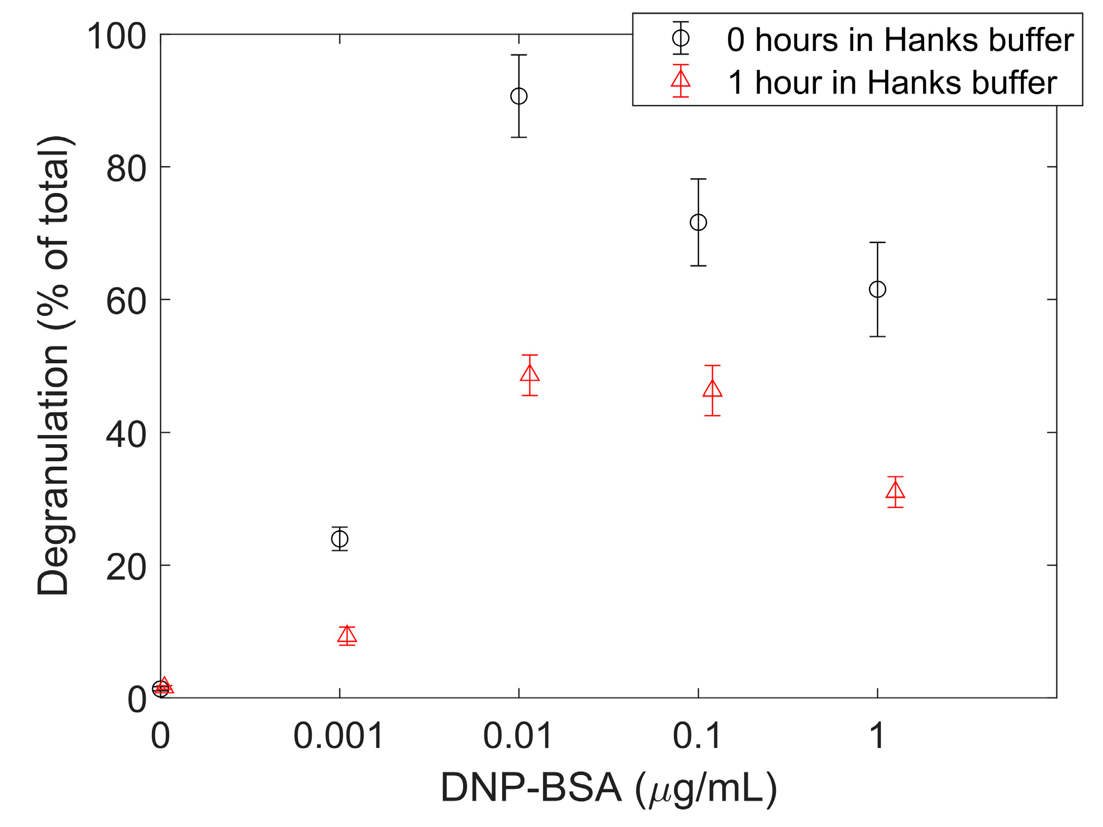
Using dark images and TIRF illumination profile images, image stack pixel intensity values were corrected, and pixel units converted from ADUs to photo electrons. The average pixel intensity within FcεRI-centric synapses for all three Hanks buffer conditions increased linearly at a rate of 0.42 ± 0.02 photo electrons per pixel per percent IgE488. Hanks buffer has been widely used over decades as an imaging buffer when RBL-2H3 cells are imaged with a light microscope. Time-dependent effects of the Hanks buffer on the degranulation of RBL-2H3 cells were investigated by measuring extracellular levels of β-hexosaminidase. DNP-bovine serum albumin (BSA) concentration-dependent degranulation of cells that were suspended in Hanks buffer for an hour prior to performing the degranulation assay decreased by 38%–65% compared to cells that were kept in cell media until the degranulation assay was performed. This decrease in degranulation may be an indication that RBL-2H3 cells become stressed when suspended in Hanks buffer for an extended time. Therefore, one further potential research project that could be based on this dataset includes statistical analysis of IgE-FcεRI receptor kinetics when RBL-2H3 cells become stressed. Additionally, the dataset can be used to investigate the concentration fluctuation of the IgE-FcεRI receptor signaling complex within the FcεRI-centric synapse to determining the receptor signaling complex size [30].

2. Data Description

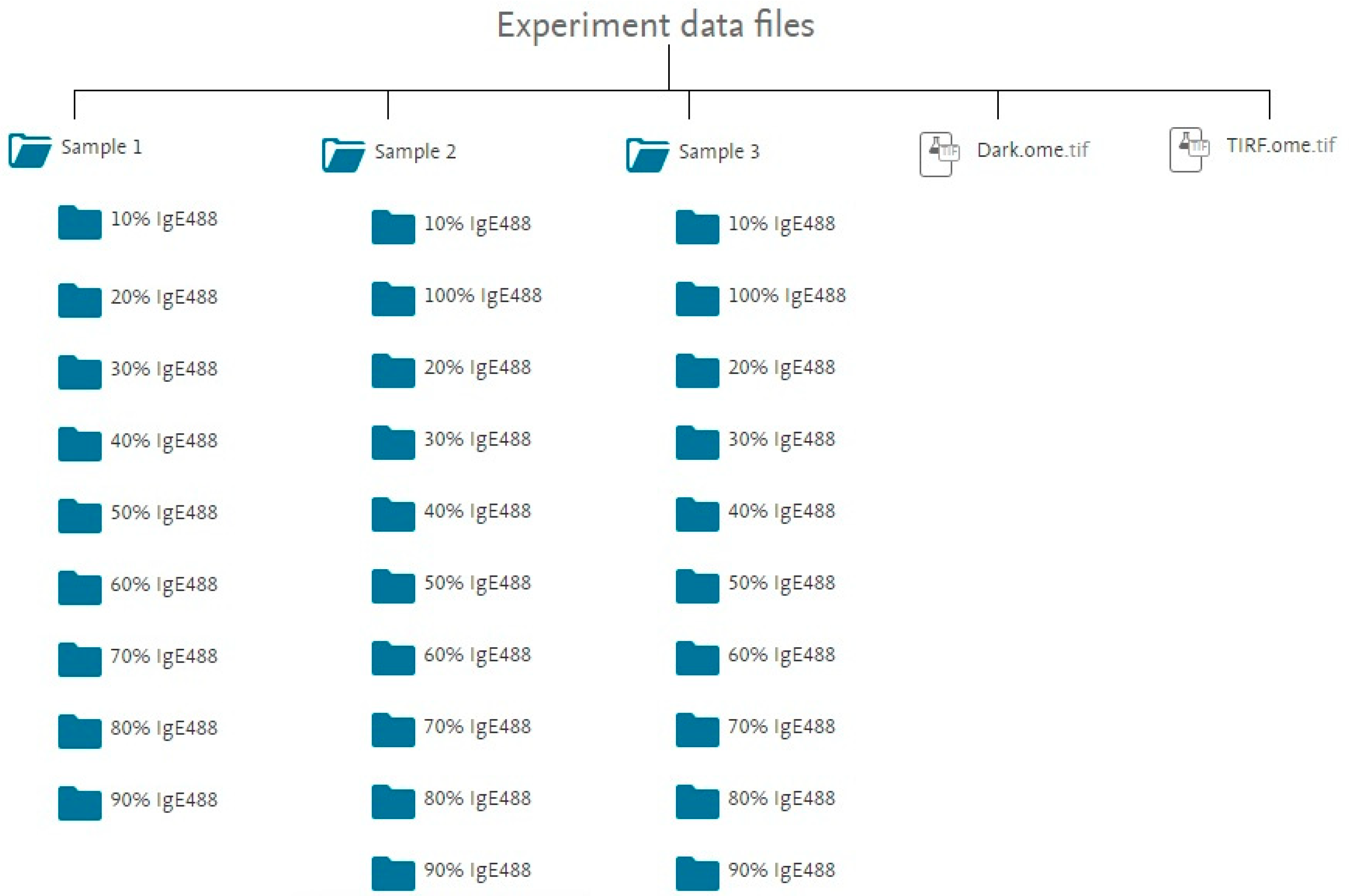
The data are provided as OME-TIFF (.ome.tif) files, a life sciences file format. Information about the OME-TIFF (.ome.tif) file format as well as imaging software supporting this file format can be found in [31]. The images were captured with an electron multiplying charge-coupled device (EMCCD) camera, Evolve 512 Delta (Photometrics, Tucson, USA) operated by Micro-Manager [32]. The dataset contains 482 RBL-2H3 model synapse image stacks, a dark field image stack (Dark.ome.tif), and a TIRF illumination image stack (TIRF.ome.tif) [33]. All images are 128 × 128 pixel. Each image stack contains 500 individual images with a camera exposure of 5 ms per image and a pixel size of 107 nm. The RBL-2H3 model synapse data is organized into three folders called Sample 1, Sample 2, and Sample 3. Cells of Sample 1, Sample 2, and Sample 3 were kept in Hanks buffer for a few minutes, about 30 min, or about 1 h before cells were added to the supported lipid bilayer, respectively. Each of these folders contains subfolders for ten different fluorescent anti-DNP IgE (IgE488) concentrations. IgE488 was increased from 10% to 90% by increments of 10% for Sample 1 and increased from 10% to 100% by increments of 10% for Sample 2 and Sample 3. Each subfolder contains between 15 and 26 image stacks, with the majority of subfolders containing 16 image stacks. Each image stack contains 500 image frames of a single RBL-2H3 cell model synapse. Figure 2 shows a flowchart of the data folder structure.
File naming convention for OME-TIFF (.ome.tif) image stacks found in a subfolder is as follows:
IgE488_[%]per_Sample[#]_[cell #]_MMStack.ome.tif
  • [%] refers to the percentage of IgE488 and 100% - [%] gives the corresponding percentage of IgEdark for a given image stack.
  • [#] is the sample number. [#] can be 1, 2, or 3.
  • [cell #] is an integer number ranging from 1 to 26, identifying a particular cell for a given IgE488 percentage and sample number.
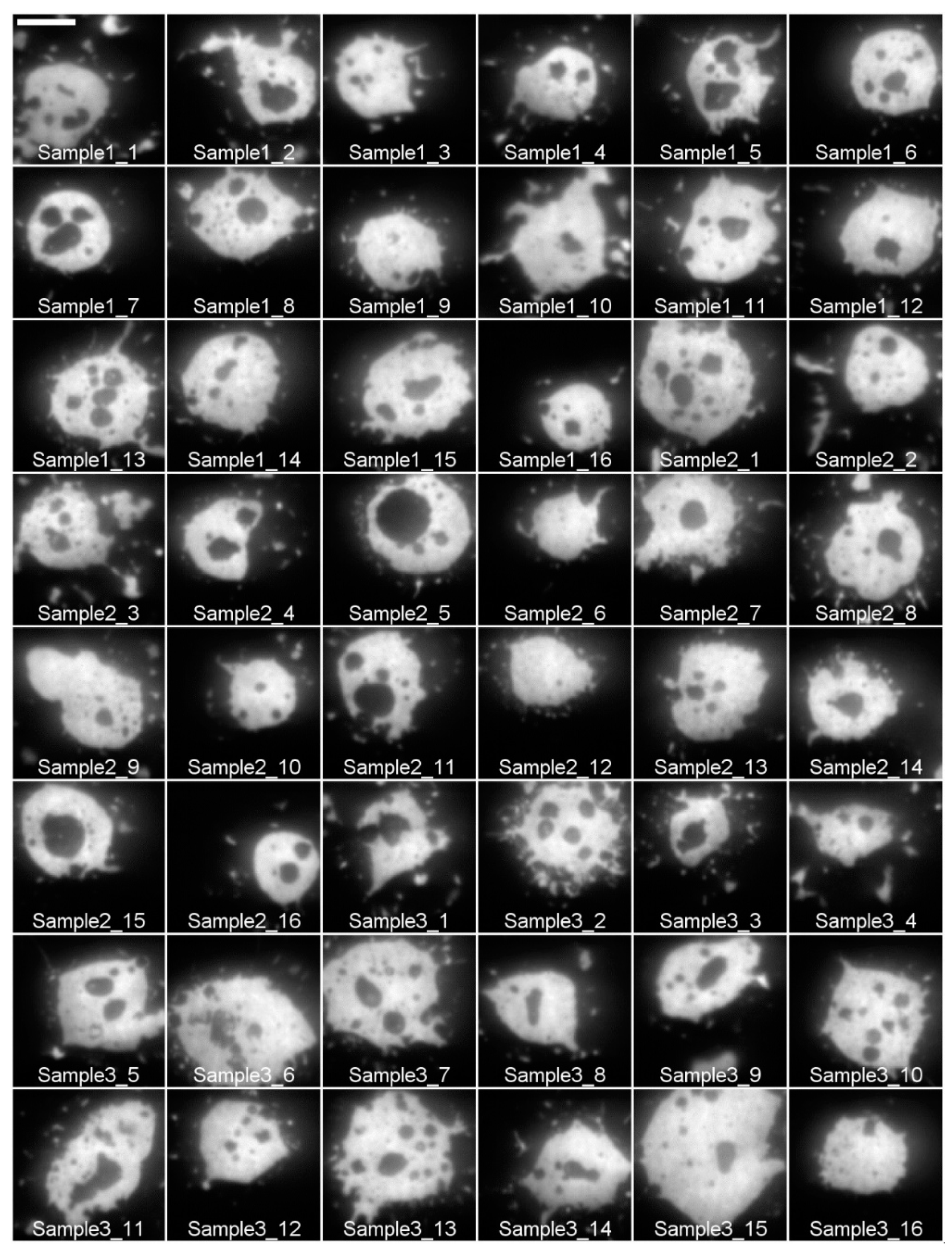
For example, IgE488_80per_Sample1_10_MMStack.ome.tif corresponds to the image stack for cell number 10 in Sample 1 labeled with 80% IgE488 and 20% IgEdark. Figure 3 depicts a gallery of all RBL-2H3 cell model synapses labeled with 80% IgE488 and 20% IgEdark contained in this dataset.

3. Methods

This section discusses the methods used to collect the data. First, the RBL-2H3 cell culture is described, and the steps taken to label cells with different percentages of IgE488 and IgEdark are outlined. The second section describes the preparation of SLBs, and the third section describes TIRF microscopy with corresponding imaging parameters. The third section describes how camera noise and camera gain were calculated and how the background intensity and TIRF illumination profile image stacks were collected. The last section outlines an IgE-dependent degranulation assay for RBL-2H3 cells.

3.1. Labeling of RBL-2H3 Cells at Varying Fluorescent and Dark Anti-DNP IgE Concentrations

The RBL-2H3 cell line was purchased from ATCC (ATTC®, Manassas, USA, CRL-2256). RBL-2H3 cells were maintained in minimal essential medium supplemented with 10% fetal bovine serum, 1% penicillin streptomycin, and 1% L-glutamine. Anti-DNP IgE was purchased from Sigma-Aldrich (~1mg/mL, clone SPE-7, Sigma-Aldrich, St Louis, USA, D8406). Non-fluorescent anti-DNP-IgE (IgEdark) was conjugated with 0.15 mM DyLight 488 N-hydroxysuccinimide ester (Thermo Fisher Scientific, Waltham, USA, 46403) according to the manufacturer’s protocols to produce fluorescent anti-DNP-IgE (IgE488) and obtain a mole ratio of 1.02 ± 0.08 mole dye per mole protein. A spectrophotometer (NanoDrop™ 2000, Thermo Fisher Scientific, Waltham, USA) was used to measure the absorbance, which was then used to calculate the anti-DNP-IgE concentration and the mole fluorescent dye to mole protein ratio. A concentration of 6.59 ± 0.53 μM or 1.19 ± 0.10 μg/μL was calculated for the IgE488 and 7.73 ± 0.26 μM or 1.39 ± 0.05 μg/μL for the IgEdark. These concentrations were then used to calculate the volume needed of each to produce a percentage of IgE488 in solution that increased from 10% to 100% by increments of 10% and IgEdark in solution that decreased from 90% to 0% by increments of 10%. To label, the calculated volumes of IgE488 and IgEdark were added to the RBL-2H3 cells suspended in 10 mL of cell media the day prior to imaging and allowed to incubate overnight (see Table 1). Immediately before experimental data was taken, cells were removed from the suspension dish and resuspended in Hanks buffer. The buffer consists of Hank’s balanced salt solution without MgCl2 [34] supplemented with 10 mM 4-(2-hydroxyethyl)-1-piperazineethanesulfonic acid (HEPES) and 0.05% BSA. Cells of Sample 1 were kept in Hanks buffer for a few minutes before cells were added to the SLB. Cells from Sample 2 were kept in Hanks buffer for about half an hour before cells were added to the SLB. Cells from Sample 3 were kept in Hanks buffer for about one hour before cells were added to the SLB.

3.2. Supported Lipid Bilayer

Spontaneous liposome fusion was used to produce the SLB [11]. Liposomes composed of 1.3 mM 1-palmitoyl-2-oleoyl-sn-glycero-3-phosphocholine (POPC, Avanti Polar Lipids, Inc., Alabama, USA) and 25 mol% N-dinitrophenyl-aminocaproyl phosphatidylethanolamine (DNP-Cap PE, Avanti Polar Lipids, Inc., Alabama, USA) were made as follows. The chloroform used to suspend the lipids was evaporated under air flow and placed in a vacuum chamber for 1 h to complete the drying process. The lipids were hydrated in 1 mL phosphate buffered saline (PBS, pH 7.4, Fisher BioReagents, Thermo Fisher Scientific, Waltham, USA, BP243820), transferred to a 1.5 mL epitube surrounded by ice and sonicated for 10 min with a probe sonicator. The SLB was prepared on coverslips that had been cleaned prior to the experiment with piranha solution, a mixture of sulfuric acid and hydrogen peroxide. A small amount of liposomes, 50 μL, were placed on a petri dish, and a coverslip was placed over the lipids, which were then allowed to incubate for 15 min at 37 °C to form a laterally mobile bilayer. The coverslip was then transferred to an imaging chamber while submerged under distilled H2O. The imaging chamber was washed, multiple times, with 400–500 μL of Hanks buffer before the prepared cells were added. To assure that a central receptor patch was formed before imaging, the cells were allowed to incubate for 15 min on the SLB at 37 °C.
The fluidity of the SLB was tested using a fluorescence recovery after photobleaching (FRAP) method. To do this, liposomes composed of POPC, 25 mol% DNP-Cap-PE, and 0.5% BODIPY-conjugated lipid (Thermo Fisher Scientific, Waltham, USA, D3803) were used to create a SLB. FRAP experiments on the SLB were performed on a confocal microscope (SP5, Leica, , Buffalo Grove, USA). The SLB was maintained at 37 °C using an objective heater (Bioptechs, Butler, USA). Using the Leica FRAP software, fluorescence recovery curves were fitted to a diffusion model yielding a diffusion coefficient of 1.1 ± 0.3 µm2/sec and an immobile fraction of 9.9 ± 7.0%. BODIPY-labeled bilayer uniformity was checked using the widefield mode of the microscope. The bilayer appeared uniform and intact throughout the coverslip surface.

3.3. TIRF Microscopy

Objective-based TIRF microscopy of the cells was performed using an S-TIRF module (Spectral Applied Research, Richmond Hill, Canada) attached to a Leica DMI3000B inverted microscope. A 100× and 1.47 numerical aperture oil immersion objective (Leica, Buffalo Grove, USA) in conjunction with a 1.5× tube lens was used for imaging, resulting in an image pixel size of 107 nm. The samples were excited with a 488 nm laser (Coherent Inc., Santa Clara, USA). The penetration depth of the evanescent wave was set to 70 nm. A sample temperature of 37 °C was maintained throughout the imaging process with an objective heater (Bioptechs, Butler, USA). A 525/50 nm single-bandpass filter (Chroma, Bellows Falls, USA) was used to collect fluorescence. The images were captured with an EMCCD camera, Evolve 512 Delta (Photometrics, Yucson, USA) operated by Micro-Manager [32]. The EMCCD camera was set to a multiplier gain of 100. The 128 × 128 pixel region of interest (ROI) allowed for each cell to be imaged with an exposure time of 5 ms.

3.4. Calibration and Image Correction

For images contained in this dataset to be useful for further analysis, corrections need to be made to account for background contributions and non-uniform TIRF illumination. Additionally, the collected signal given in analog-digital-units (ADUs) must be converted to photon equivalents or photo electrons using camera gain (g). This signal must then further be corrected by accounting for noise contributions. Noise contributions for EMCCD cameras include Poisson noise, readout noise, dark current noise, and spurious noise. Noise contributions due to the dark current and spurious noise are at least one order of magnitude smaller than typical readout noise contributions and hence are typically ignored [14]. To calculate camera readout noise and gain, a stationary test sample containing the full range of intensities can be used. An appropriate calibration image, which samples all possible intensities, was obtained from out-of-focus fluorescent beads [36]. A time series of 500 images of orange beads (Invitrogen, Thermo Fisher Scientific, Waltham, USA, FluoSpheres® Fluorescent Color Kit, F10720) mounted on a microscope cover glass was taken. Following calibration procedures outlined in references [36] and [13], the camera gain g for this dataset was 0.006 photo electrons per ADU. The readout noise Nread was 0.529 photo electrons. To correct for background intensity, 500 images were taken at an exposure of 5 ms with the laser turned off. To correct for non-uniform TIRF illumination, a 1 mm thick, yellow autofluorescent plastic slide (Chroma, Bellows Falls, USA) was illuminated in TIRF mode, and an image stack containing 500 images was taken.

3.5. Degranulation Assay

Since the passage number can impact the degranulation process in RBL-2H3 cells, time-dependent effects of Hanks buffer together with concentration-dependent effects of DNP-BSA in solution on the degranulation of RBL-2H3 cells were investigated by measuring extracellular levels of β-hexosaminidase [37]. The degranulation assay was performed on RBL-2H3 cells that were kept in cell media or exposed to Hanks buffer for one hour prior to the start of the degranulation assay. To determine the strength of mast cell degranulation, the amount of β-hexosaminidase, a secreted mast cell enzyme was measured. β-Hexosaminidase, which is generally present in the lysosome, is essential for glycoprotein metabolism in the maintenance of cell homeostasis. In mast cells, large amounts of β-hexosaminidase are present in the granules [38]. In these experiments, 300 × 105 RBL-2H3 cells per well were seeded in two cell culture-treated 24-well plates (ThermoFisher Scientific, Waltham, USA, 142475) and primed for 24 h with 0.5 µg/mL IgEdark in cell media. After 24 h, cells in plate one were washed twice with Hanks buffer and resuspended in a Hanks buffer for one hour. Cells in plate two were also washed twice with Hanks buffer but then resuspended in cell media for one hour. Then the degranulation assay was performed on both plates following the method of Smith et al. [37] with anti-DNP IgE-primed RBL-2H3 cells exposed to 0, 0.001, 0.01, 0.1, or 1.0 µg/mL DNP-BSA (Sigma-Aldrich, St Louis, USA). Supernatants were then collected and the percent of total β-hexosaminidase content released into the medium over the incubation time period were calculated. Figure 4 depicts the release expressed as a percentage of total cellular content for the different experimental conditions. Besides for spontaneous release (0 µg/mL DNP-BSA), the release for cells kept in Hanks buffer instead of cell media for one hour decreased between 38%–65%, depending on DNP-BSA concentrations. The percentage of total cellular hexosaminidase released for 0.1 µg/mL DNP-BSA for cells kept in cell media prior to the start of the degranulation assay is consistent with previous experiments [11,37].

4. User Notes

To perform statistical image analysis on this dataset, the following image processing steps should be performed. Image processing is necessary to correct image sequences of the RBL-2H3 cell model synapse for dark current (background intensity), uneven TIRF illumination, and camera noise, as well as to convert original pixel values in ADUs to photo electrons (e). Image processing can be performed in MATLAB in conjunction with DIPimage, an image processing library [39] or with ImageJ, an image processing software freely available in the public domain [40]. First, subtract the dark image D (average of 500 background intensity images) in units of ADU from each image I in units of ADU, and then multiply the image by the TIRF illumination profile T to perform a so-called flat-field correction [41]. To obtain T, compute the average of 500 TIRF illumination images, and then divide this average image by its maximum pixel intensity such that the maximum pixel value of image T is one. Then multiply the resulting image by camera gain g = 0.006 photo electrons/ADU and subtract the readout noise Nread = 0.529 photo electrons to obtain the final image S. Equation (1) outlines the calculation to obtain image S. Pixel values of S will be given in photo electrons.
S = [(I − D) T] g − Nread
To facilitate the use of this dataset, image stacks to obtain D (Dark.ome.tif) and T (TIRF.ome.tif) are included in the data repository.
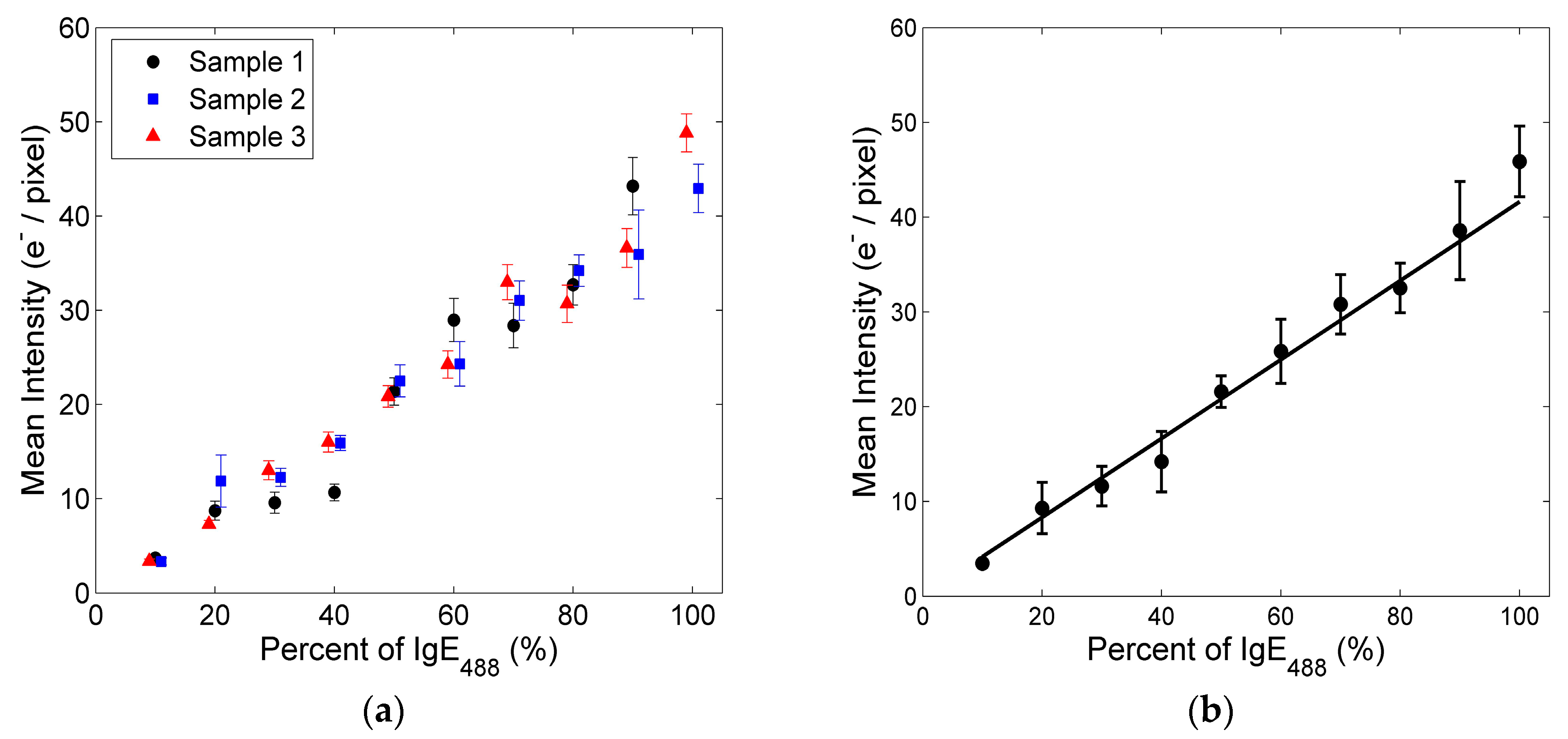
It is expected that the concentration of fluorescently labeled IgE-FcεRI receptor signaling complexes within synaptic patches increases linearly with an increasing percentage of IgE488. This expected linear trend was verified by comparing the average pixel intensities of imaged FcεRI-centric synapses for different % IgE488. The mean fluorescent intensity in units of photo electrons (e) per pixel was calculated by first averaging pixel intensities over individual image stacks after applying Equation (1) and then averaging the intensities of 5–10 square regions (10 × 10 pixels each) within individual FcεRI-centric synapses. Regions within the synaptic patches that contained holes (i.e., no IgE488) were not included. Figure 5a shows that the mean pixel intensity inside synaptic patches increased at similar rates as a function of % IgE488 for each sample. After averaging pixel intensities for all samples, a line of best fit through the origin was fitted to the data. Figure 5b depicts this fit. The average pixel intensity within FcεRI-centric synapses for all three Hanks buffer conditions increased linearly at a rate of 0.42 ± 0.02 photo electrons per pixel per IgE488.

Author Contributions

Conceptualization, K.S.; Formal analysis, R.D. and K.S.; Investigation, R.D.; Methodology, K.S.; Supervision, K.S.; Visualization, R.D. and K.S.; Writing—original draft, R.D. and K.S.; Writing—review & editing, R.D. and K.S.

Funding

Research reported in this publication was supported by the National Institute of General Medical Sciences of the National Institutes of Health under award number 1R15GM128166-01. This work was also supported by the University of Colorado Colorado Springs (UCCS) center of the University of Colorado BioFrontiers Institute and the UCCS Undergraduate Research Academy.

Acknowledgments

The authors thank James L. Thomas for useful discussions and guidance.

Conflicts of Interest

The authors declare no conflict of interest. The funders had no role in the design of the study; in the collection, analyses, or interpretation of data; in the writing of the manuscript, or in the decision to publish the results.

References

  1. Radhakrishnan, K.; Halász, A.; Vlachos, D.; Edwards, J.S. Quantitative understanding of cell signaling: The importance of membrane organization. Curr. Opin. Biotechnol. 2010, 21, 677–682. [Google Scholar] [CrossRef] [PubMed]
  2. Metzger, H. Transmembrane signaling: The joy of aggregation. J. Immunol. 1992, 149, 1477–1487. [Google Scholar] [PubMed]
  3. Sever, R.; Brugge, J.S. Signal transduction in cancer. Cold Spring Harb. Perspect. Med. 2015, 5, a006098. [Google Scholar] [CrossRef] [PubMed]
  4. Sigalov, A.B. Transmembrane signaling: From understanding to action. Self. Nonself. 2010, 1, 341–342. [Google Scholar] [CrossRef]
  5. Colgan, J.D.; Hankel, I.L. Signaling pathways critical for allergic airway inflammation. Curr. Opin. Allergy Clin. Immunol. 2010, 10, 42–47. [Google Scholar] [CrossRef] [PubMed] [Green Version]
  6. Galli, S.J.; Tsai, M.; Piliponsky, A.M. The development of allergic inflammation. Nature 2008, 454, 445–454. [Google Scholar] [CrossRef] [Green Version]
  7. Thomas, J.L.; Feder, T.J.; Webb, W.W. Effects of protein concentration on IgE receptor mobility in rat basophilic leukemia cell plasma membranes. Biophys. J. 1992, 61, 1402–1412. [Google Scholar] [CrossRef] [Green Version]
  8. Thomas, J.L.; Holowka, D.; Baird, B.; Webb, W.W. Large-scale co-aggregation of fluorescent lipid probes with cell surface proteins. J. Cell Biol. 1994, 125, 795–802. [Google Scholar] [CrossRef]
  9. Posner, R.G.; Subramanian, K.; Goldstein, B.; Thomas, J.; Feder, T.; Holowka, D.; Baird, B. Simultaneous cross-linking by two nontriggering bivalent ligands causes synergistic signaling of IgE Fc epsilon RI complexes. J. Immunol. 1995, 155, 3601–3609. [Google Scholar]
  10. Passante, E.; Ehrhardt, C.; Sheridan, H.; Frankish, N. RBL-2H3 cells are an imprecise model for mast cell mediator release. Inflamm. Res. 2009, 58, 611–618. [Google Scholar] [CrossRef]
  11. Carroll-Portillo, A.; Spendier, K.; Pfeiffer, J.; Griffiths, G.; Li, H.; Lidke, K.A.; Oliver, J.M.; Lidke, D.S.; Thomas, J.L.; Wilson, B.S.; et al. Formation of a mast cell synapse: Fc epsilon RI membrane dynamics upon binding mobile or immobilized ligands on surfaces. J. Immunol. 2010, 184, 1328–1338. [Google Scholar] [CrossRef]
  12. Spendier, K.; Thomas, J.L. Mast Cells: Phenotypic Features, Biological Functions, and Role in Immunity; Nova Science Publishers: Hauppauge, NY, USA, 2013; Chapter 2- Spatial Patterns in Mast Cell Activation; ISBN 978-162-618-166-3. [Google Scholar]
  13. Spendier, K.; Lidke, K.A.; Lidke, D.S.; Thomas, J.L. Single-particle tracking of immunoglobulin e receptors (FcRI) in micron-sized clusters and receptor patches. FEBS Lett. 2012, 586, 416–421. [Google Scholar] [CrossRef]
  14. Spendier, K.; Carroll-Portillo, A.; Lidke, K.A.; Wilson, B.S.; Timlin, J.A.; Thomas, J.L. Distribution and dynamics of rat basophilic leukemia immunoglobulin E receptors (FcepsilonRI) on planar ligand-presenting surfaces. Biophys. J. 2010, 99, 388–397. [Google Scholar] [CrossRef]
  15. Machado, R.; Bendesky, J.; Brown, M.; Spendier, K.; Hagen, G.M. Imaging Membrane Curvature inside a FcεRI-Centric Synapse in RBL-2H3 Cells Using TIRF Microscopy with Polarized Excitation. J. Imaging 2019, 5, 63. [Google Scholar] [CrossRef]
  16. Jung, S.-R.; Hille, B. Optical approaches for visualization of arrestin binding to muscarinic receptor. Methods Cell Biol. 2019, 149, 1–18. [Google Scholar]
  17. Kalkur, R.S.; Ballast, A.C.; Triplett, A.R.; Spendier, K. Effects of deuterium oxide on cell growth and vesicle speed in RBL-2H3 cells. PeerJ 2014, 2, e553. [Google Scholar] [CrossRef] [Green Version]
  18. Yi, J.; Balagopalan, L.; Nguyen, T.; McIntire, K.M.; Samelson, L.E. TCR microclusters form spatially segregated domains and sequentially assemble in calcium-dependent kinetic steps. Nat. Commun. 2019, 10, 277. [Google Scholar] [CrossRef] [PubMed]
  19. Tolar, P.; Hanna, J.; Krueger, P.D.; Pierce, S.K. The Constant Region of the Membrane Immunoglobulin Mediates B Cell-Receptor Clustering and Signaling in Response to Membrane Antigens. Immunity 2009, 30, 44–55. [Google Scholar] [CrossRef] [Green Version]
  20. Andrews, N.L.; Lidke, K.A.; Pfeiffer, J.R.; Burns, A.R.; Wilson, B.S.; Oliver, J.M.; Lidke, D.S. Actin restricts FcɛRI diffusion and facilitates antigen-induced receptor immobilization. Nat. Cell Biol. 2008, 10, 955–963. [Google Scholar] [CrossRef]
  21. Su, X.; Ditlev, J.A.; Hui, E.; Xing, W.; Banjade, S.; Okrut, J.; King, D.S.; Taunton, J.; Rosen, M.K.; Vale, R.D. Phase separation of signaling molecules promotes T cell receptor signal transduction. Science 2016, 352, 595–599. [Google Scholar] [CrossRef] [Green Version]
  22. Oppong, E.; Hedde, P.N.; Sekula-Neuner, S.; Yang, L.; Brinkmann, F.; Dörlich, R.M.; Hirtz, M.; Fuchs, H.; Nienhaus, G.U.; Cato, A.C.B. Localization and Dynamics of Glucocorticoid Receptor at the Plasma Membrane of Activated Mast Cells. Small 2014, 10, 1991–1998. [Google Scholar] [CrossRef]
  23. Varma, R.; Campi, G.; Yokosuka, T.; Saito, T.; Dustin, M.L. T Cell Receptor-Proximal Signals Are Sustained in Peripheral Microclusters and Terminated in the Central Supramolecular Activation Cluster. Immunity 2006, 25, 117–127. [Google Scholar] [CrossRef] [Green Version]
  24. Davis, R.E.; Ngo, V.N.; Lenz, G.; Tolar, P.; Young, R.M.; Romesser, P.B.; Kohlhammer, H.; Lamy, L.; Zhao, H.; Yang, Y.; et al. Chronic active B-cell-receptor signalling in diffuse large B-cell lymphoma. Nature 2010, 463, 88–92. [Google Scholar] [CrossRef] [Green Version]
  25. Axelrod, D. Cell-substrate contacts illuminated by total internal reflection fluorescence. J. Cell Biol. 1981, 89, 141–145. [Google Scholar] [CrossRef]
  26. Monks, C.R.F.; Freiberg, B.A.; Kupfer, H.; Sciaky, N.; Kupfer, A. Three-dimensional segregation of supramolecular activation clusters in T cells. Nature 1998, 395, 82–86. [Google Scholar] [CrossRef]
  27. Kaizuka, Y.; Douglass, A.D.; Varma, R.; Dustin, M.L.; Vale, R.D. Mechanisms for segregating T cell receptor and adhesion molecules during immunological synapse formation in Jurkat T cells. Proc. Natl. Acad. Sci. USA 2007, 104, 20296–20301. [Google Scholar] [CrossRef] [Green Version]
  28. Carroll-Portillo, A.; Cannon, J.L.; Te Riet, J.; Holmes, A.; Kawakami, Y.; Kawakami, T.; Cambi, A.; Lidke, D.S. Mast cells and dendritic cells form synapses that facilitate antigen transfer for T cell activation. J. Cell Biol. 2015, 210, 851–864. [Google Scholar] [CrossRef]
  29. Mantri, C.K.; John, A.L. St. Immune synapses between mast cells and γδ T cells limit viral infection. J. Clin. Investig. 2019, 129, 1094–1108. [Google Scholar] [CrossRef]
  30. Drawbond, R.; Thomas, J.; Spendier, K. Suppressed concentration fluctuations in rat basophilic leukemia cell synapse: (indirect) evidence for large signaling complexes. Bull. Am. Phys. Soc. 2014, 59, 11. [Google Scholar]
  31. The OME-TIFF Format—OME Data Model and File Formats 5.6.3 Documentation. Available online: https://docs.openmicroscopy.org/ome-model/5.6.3/ome-tiff/ (accessed on 19 May 2019).
  32. Edelstein, A.; Amodaj, N.; Hoover, K.; Vale, R.; Stuurman, N. Computer Control of Microscopes Using µManager. In Current Protocols in Molecular Biology; John Wiley & Sons, Inc.: Hoboken, NJ, USA, 2010; Volume 92, pp. 14.20.1–14.20.17. [Google Scholar]
  33. Drawbond, R.; Spendier, K. TIRF Microscopy Image Sequences of Fluorescent IgE-FcεRI inside Immunological Model Synapse in RBL-2H3 Cells Dataset. Mendeley Data 2019, v2. [Google Scholar]
  34. Hank’s Balanced Salt Solution (HBSS) without Phenol Red. Cold Spring Harb. Protoc. 2006, 2006, pdb.rec548.
  35. Taylor, J.R.; John, R. An Introduction to Error Analysis: The Study of Uncertainties in Physical Measurements; University Science Books: Sausalito, CA, USA, 1997; ISBN 978-093-570-275-0. [Google Scholar]
  36. Lidke, K.A.; Rieger, B.; Lidke, D.S.; Jovin, T.M. The role of photon statistics in fluorescence anisotropy imaging. IEEE Trans. Image Process. 2005, 14, 1237–1245. [Google Scholar] [CrossRef]
  37. Smith, A.J.; Pfeiffer, J.R.; Zhang, J.; Martinez, A.M.; Griffiths, G.M.; Wilson, B.S. Microtubule-dependent transport of secretory vesicles in RBL-2H3 cells. Traffic 2003, 4, 302–312. [Google Scholar] [CrossRef]
  38. Fukuishi, N.; Murakami, S.; Ohno, A.; Yamanaka, N.; Matsui, N.; Fukutsuji, K.; Yamada, S.; Itoh, K.; Akagi, M. Does β-hexosaminidase function only as a degranulation indicator in mast cells? The primary role of β-hexosaminidase in mast cell granules. J. Immunol. 2014, 193, 1886–1894. [Google Scholar] [CrossRef]
  39. DIPimage & DIPlib. Available online: http://www.diplib.org/ (accessed on 1 February 2019).
  40. ImageJ. Image processing and analysis in Java. Available online: https://imagej.nih.gov/ij/index.html (accessed on 1 February 2019).
  41. Model, M.A.; Burkhardt, J.K. A standard for calibration and shading correction of a fluorescence microscope. Cytometry 2001, 44, 309–316. [Google Scholar] [CrossRef]
Figure 1. (a) TIRF microscope image of RBL-2H3 cell FcεRI-centric synapse. Prior to imaging, the cell was loaded with 80% fluorescent anti-DNP IgE and 20% dark anti-DNP IgE. Scale bar represents 5 µm; (b) Schematic of RBL-2H3 cell coming into contact with a supported lipid bilayer with monovalent ligand (25 mol% DNP-lipid) in bilayer.
Data 04 00111 g001
Figure 2. Flowchart of the experiment data files folder and subfolder structure of the published Mendeley data [33]. Cells of Sample 1, Sample 2, and Sample 3 were kept in Hanks buffer for a few minutes, about 30 min, or about 1 h before cells were added to the supported lipid bilayer, respectively. Each subfolder contains between 15 and 26 image stacks of individual RBL-2H3 cell FcεRI-centric synapses saved as ome.tif files as indicated by the number within curved brackets. A dark field image stack (Dark.ome.tif) and a TIRF illumination image stack (TIRF.ome.tif) are also contained in the experimental data files. Each image stack contains a sequence of 500 images.
Data 04 00111 g002
Figure 3. Gallery of images of RBL-2H3 cell model synapses labeled with 80% IgE488 and 20% IgEdark in contact with supported lipid bilayers containing mobile ligand. The gallery shows 16 images for each of the three samples. The scale bar in the first image panel represents 5 µm and applies to all remaining panels.
Data 04 00111 g003
Figure 4. Prolonged RBL-2H3 cell exposure to Hanks buffer inhibits exocytosis in RBL-2H3 cells. Cells were either resuspended for one hour in cell media (black open circles) or in Hanks buffer (red open triangles) prior to the start of a DNP-BSA dose-dependent degranulation assay. Exocytosis or degranulation was measured as the percentage of total cellular hexosaminidase released.
Data 04 00111 g004
Figure 5. Mean intensity of fluorescently labeled IgE-FcεRI receptor signaling complexes within synaptic patches as a function of percent fluorescent anti-DNP IgE (IgE488) added to solution: (a) Mean intensity for each sample. Sample 1 (solid black circles), Sample 2 (solid blue squares), and Sample 3 (solid red triangles) were kept in Hanks buffer for a few minutes, about 30 min, or about 1 h before cells were added to the supported lipid bilayer, respectively. Error bars represent the standard deviations; (b) Mean intensity of all three samples averaged together with error bars representing the standard deviations. Solid line represents a weighted linear fit y = a x. The slope a of this fit was 0.42 ± 0.01 photo electrons (e) per pixel per percent (%) IgE488 in solution.
Data 04 00111 g005
Table 1. Volumes of IgE488 and IgEdark added to RBL-2H3 cell suspension 24 h prior to imaging and corresponding concentrations for different % IgE488 and % IgEdark.
% IgE488 (%)% IgEdark (%)Volume of IgE488 Added to Cell Suspension (µL) 1Volume of IgEdark Added to Cell Suspension (µL) 1Concentration of IgE488 in Cell Suspension (μg/mL) 2Concentration of IgEdark in Cell Suspension (μg/mL) 2
10900.5 ± 0.13.8 ± 0.10.06 ± 0.10.53 ± 0.3
20801.0 ± 0.13.4 ± 0.10.12 ± 0.20.47 ± 0.2
30701.5 ± 0.13.0 ± 0.10.18 ± 0.20.41 ± 0.2
40602.0 ± 0.12.6 ± 0.10.24 ± 0.20.36 ± 0.2
50502.5 ± 0.12.1 ± 0.10.30 ± 0.30.30 ± 0.2
60403.0 ± 0.11.7 ± 0.10.36 ± 0.30.24 ± 0.2
70303.5 ± 0.11.3 ± 0.10.42 ± 0.40.18 ± 0.2
80204.0 ± 0.10.9 ± 0.10.48 ± 0.40.12 ± 0.1
90104.5 ± 0.10.4 ± 0.10.54 ± 0.50.06 ± 0.1
10005.0 ± 0.10.00.60 ± 0.50.00
1 Pipetting errors using a micropipette. 2 Errors obtained from basic propagation of errors rules [35], i.e., x and y have errors δx and δy, then the error in z = x × y is δ z z = ( δ x x ) 2 + ( δ y y ) 2 .