


Evaluation of Computer-Aided Navigation and Augmented Reality for Bicortical Mini-Implant Placement in Maxillary Expansion: An In Vitro Study

 , , and
Abstract
1. Introduction
2. Methods
2.1. Study Design
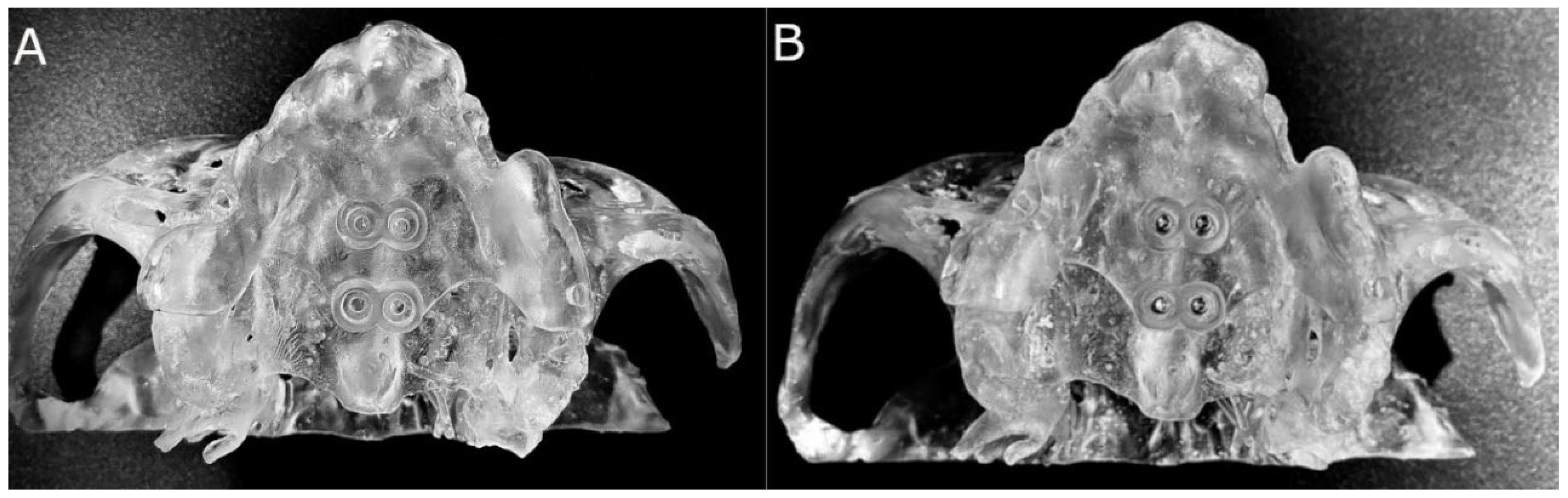
2.2. Experimental Procedure
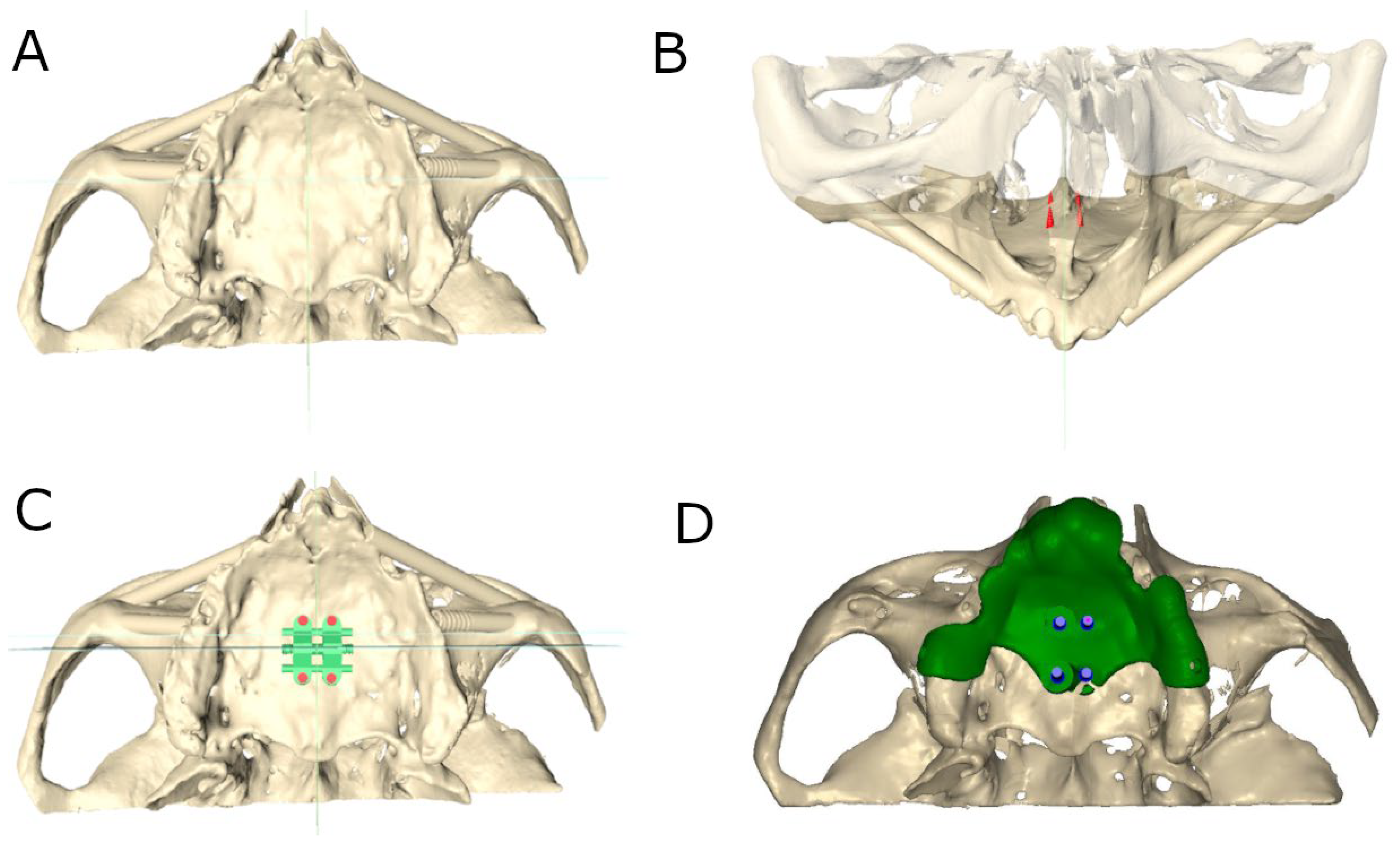
2.3. Computer-Aided Static Navigation Technique
2.4. Augmented Reality Technique
2.5. Conventional Freehand Technique
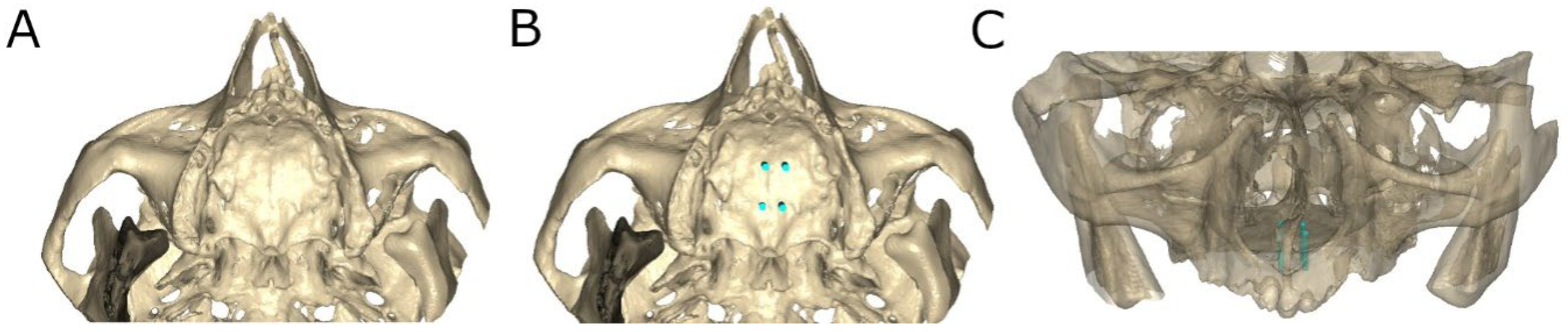
2.6. Measurement Procedure
2.7. Statistical Tests
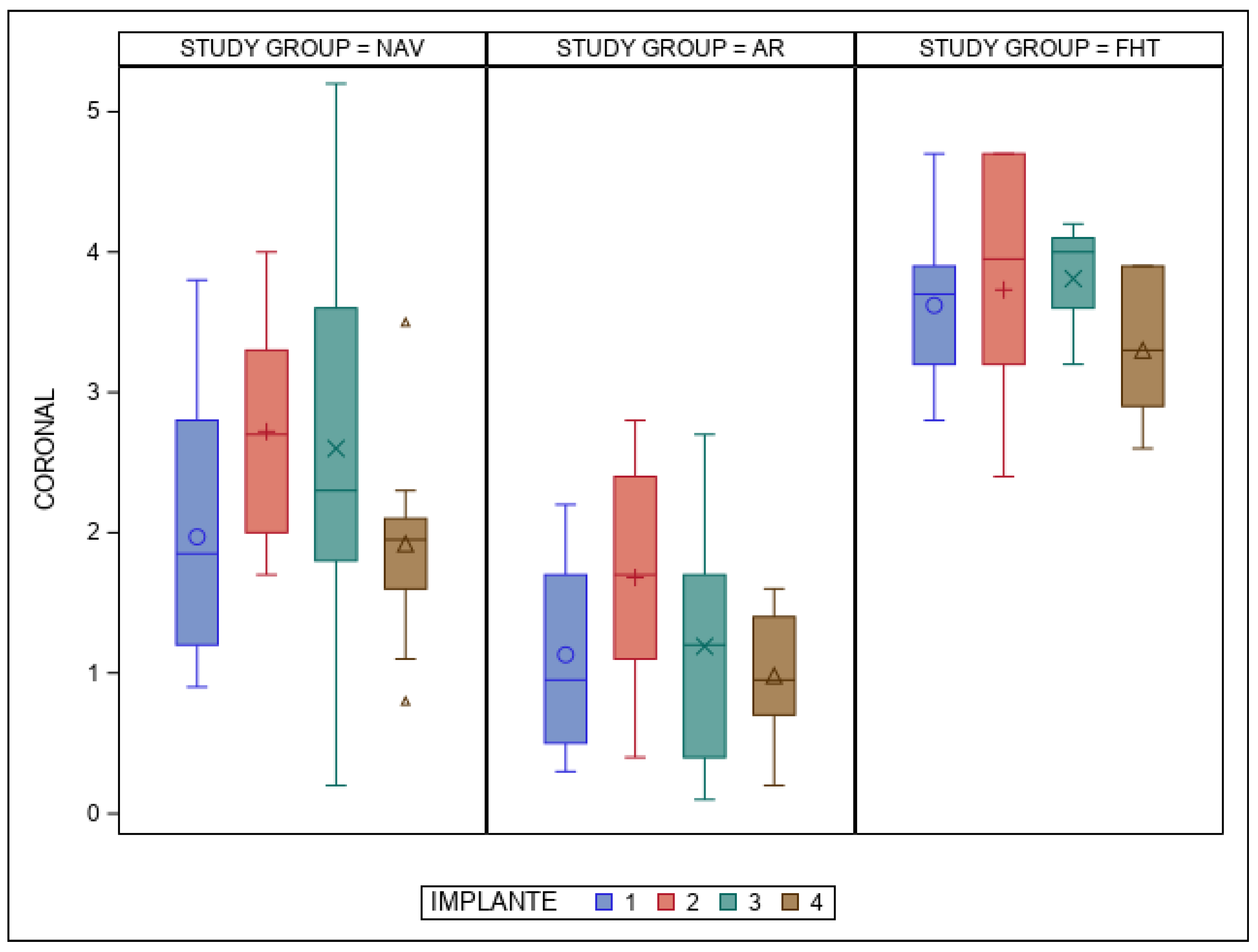
3. Results
4. Discussion
5. Conclusions
Author Contributions
Funding
Institutional Review Board Statement
Informed Consent Statement
Data Availability Statement
Conflicts of Interest
References
- McNamara, J.A. Maxillary transverse deficiency. Am. J. Orthod. Dentofac. Orthop. 2000, 117, 567–570. [Google Scholar] [CrossRef] [PubMed]
- Lagravère, M.O.; Heo, G.; Major, P.W.; Flores-Mir, C. Meta-analysis of immediate changes with rapid maxillary expansion treatment. J. Am. Dent. Assoc. 2006, 137, 44–53. [Google Scholar] [CrossRef] [PubMed]
- Haas, A.J. The treatmen to maxillary deficiency by opening the midpalatal suture. Angle. Orthod. 1965, 35, 200–217. [Google Scholar] [CrossRef] [PubMed]
- Liu, S.; Xu, T.; Zou, W. Effects of rapid max illary expansion on the midpalatal suture: A systematic review. Eur. J. Orthod. 2015, 37, 651–655. [Google Scholar] [CrossRef]
- Brunetto, D.P.; Sant’Anna, E.F.; Machado, A.W.; Moon, W. Non-surgical treatment of transverse deficiency in adults using Microimplant-assisted Rapid Palatal Expansion (MARPE). Dent. Press J. Orthod. 2017, 22, 110–125. [Google Scholar] [CrossRef]
- de Oliveira, C.B.; Ayub, P.; Ledra, I.M.; Murata, W.H.; Suzuki, S.S.; Ravelli, D.B.; Santos-Pinto, A. Microimplant assisted rapid palatal expansion vs surgically assisted rapid palatal expansion for maxillary transverse discrepancy treatment. Am. J. Orthod. Dentofac. Orthop. 2021, 159, 733–742. [Google Scholar] [CrossRef]
- Yoon, S.; Lee, D.Y.; Jung, S.K. Influence of changing various parameters in miniscrew-assisted rapid palatal expansion: A three-dimensional finite element analysis. Korean J. Orthod. 2019, 49, 150–160. [Google Scholar] [CrossRef]
- Moon, W. An interview with Won Moon. Dent. Press J. Orthod. 2013, 18, 12–28. [Google Scholar] [CrossRef]
- Choi, S.H.; Shi, K.K.; Cha, J.Y.; Park, Y.C.; Lee, K.J. Nonsurgical miniscrew-assisted rapid maxillary expansion results in acceptable stability in young adults. Angle Orthod. 2016, 86, 713–720. [Google Scholar] [CrossRef]
- Ceschi, M.; Riatti, R.; Di Leonardo, B.; Contardo, L. Skeletal expansion using a miniscrew-assisted rapid palatal expansion in a 50-year-old patient. Am. J. Orthod. Dentofac. Orthop. 2022, 162, 568–579. [Google Scholar] [CrossRef]
- Liu, H.; Liu, D.X.; Wang, G.; Wang, C.L.; Zhao, Z. Accuracy of surgical positioning of orthodontic miniscrews with a computer-aided design and manufacturing template. Am. J. Orthod. Dentofac. Orthop. 2010, 137, 728.e1–728.e10; discussion 728–729. [Google Scholar] [CrossRef] [PubMed]
- Morea, C.; Hayek, J.E.; Oleskovicz, C.; Dominguez, G.C.; Chilvarquer, I. Precise insertion of orthodontic miniscrews with a stereolithographic surgical guide based on cone beam computed tomography data: A pilot study. Int. J. Oral Maxillofac. Implant. 2011, 26, 860–865. [Google Scholar]
- Qiu, L.; Haruyama, N.; Suzuki, S.; Yamada, D.; Obayashi, N.; Kurabayashi, T.; Moriyama, K. Accuracy of orthodontic miniscrew implantation guided by stereolithographic surgical stent based on cone-beam CT–derived 3D images. Angle Orthod. 2012, 82, 284–293. [Google Scholar] [CrossRef] [PubMed]
- Deguchi, T.; Nasu, M.; Murakami, K.; Yabuuchi, T.; Kamioka, H.; Takano-Yamamoto, T. Quantitative evaluation of cortical bone thickness with computed tomographic scanning for orthodontic implants. Am. J. Orthod. Dentofac. Orthop. 2006, 129, 721.e7–721.e12. [Google Scholar] [CrossRef]
- Saccucci, M.; Cipriani, F.; Carderi, S.; Di Carlo, G.; D’Attilio, M.; Rodolfino, D.; Festa, F.; Polimeni, A. Gender assessment through three-dimensional analysis of maxillary sinuses by means of cone beam computed tomography. Eur. Rev. Med. Pharmacol. Sci. 2015, 19, 185–193. [Google Scholar]
- Abbassy, M.A.; Sabban, H.M.; Hassan, A.H.; Zawawi, K.H. Evaluation of mini-implant sites in the posterior maxilla using traditional radiographs and cone-beam computed tomography. Saudi Med. J. 2015, 36, 1336–1341. [Google Scholar] [CrossRef]
- Bonangi, R.; Kamath, G.; Srivathsa, H.S.; Babshet, M. Utility of CBCT for the measurement of palatal bone thickness. J. Stomatol. Oral Maxillofac. Surg. 2018, 119, 196–198. [Google Scholar] [CrossRef]
- de Almeida, E.O.; Pellizzer, E.P.; Goiatto, M.C.; Margonar, R.; Rocha, E.P.; Freitas, A.C., Jr.; Anchieta, R.B. Computer-guided surgery in implantology: Review of basic concepts. J. Craniofacial Surg. 2010, 21, 1917–1921. [Google Scholar] [CrossRef]
- Jung, R.E.; Schneider, D.; Ganeles, J.; Wismeijer, D.; Zwahlen, M.; Hämmerle, C.H.; Tahmaseb, A. Computer technology applications in surgical implant dentistry: A systematic review. Int. J. Oral Maxillofac. Implant. 2009, 24, 92–109. [Google Scholar]
- Vercruyssen, M.; Fortin, T.; Widmann, G.; Jacobs, R.; Quirynen, M. Different techniques of static/dynamic guided implant surgery: Modalities and indications. Periodontology 2000 2014, 66, 214–227. [Google Scholar] [CrossRef]
- Farronato, M.; Maspero, C.; Lanteri, V.; Fama, A.; Ferrati, F.; Pettenuzzo, A.; Farronato, D. Current state of the art in the use of augmented reality in dentistry: A systematic review of the literature. BMC Oral Health 2019, 19, 135. [Google Scholar] [CrossRef] [PubMed]
- Kwon, H.B.; Park, Y.S.; Han, J.S. Augmented reality in dentistry: a current perspective. Acta Odontol. Scand. 2018, 76, 497–503. [Google Scholar] [CrossRef] [PubMed]
- Aichert, A.; Wein, W.; Ladikos, A.; Reichl, T.; Navab, N. Image-based tracking of the teeth for orthodontic augmented reality. Med. Image. Comput. Comput. Assist. Interv. 2012, 15 Pt 2, 601–608. [Google Scholar] [CrossRef] [PubMed]
- Paredes, N.; Colak, O.; Sfogliano, L.; Elkenawy, I.; Fijany, L.; Fraser, A.; Zhang, B.; Moon, W. Differential assessment of skeletal, alveolar, and dental components induced by microimplant-supported midfacial skeletal expander (MSE), utilizing novel angular measurements from the fulcrum. Prog. Orthod. 2020, 21, 18. [Google Scholar] [CrossRef]
- Brunetto, D.P.; Moschik, C.E.; Dominguez-Mompell, R.; Jaria, E.; Sant’Anna, E.F.; Moon, W. Mini-implant assisted rapid palatal expansion (MARPE) effects on adult obstructive sleep apnea (OSA) and quality of life: A multi-center prospective controlled trial. Prog. Orthod. 2022, 23, 3. [Google Scholar] [CrossRef]
- Shih, S.N.; Ho, K.H.; Wang, C.W.; Wang, K.L.; Hsieh, S.C.; Chang, H.M. Management of Class III Malocclusion and Maxillary Transverse Deficiency with Microimplant-Assisted Rapid Palatal Expansion (MARPE): A Case Report. Medicina 2022, 58, 1052. [Google Scholar] [CrossRef]
- Cantarella, D.; Savio, G.; Grigolato, L.; Zanata, P.; Berveglieri, C.; Lo Giudice, A.; Isola, G.; Del Fabbro, M.; Moon, W. A New Methodology for the Digital Planning of Micro-Implant-Supported Maxillary Skeletal Expansion. Med. Devices 2020, 13, 93–106. [Google Scholar] [CrossRef]
- ASTM F-1839-08; Standard Specification for Rigid Polyurethane Foam for Use as a Standard Material for Testing Orthopaedic Devices and Instruments. ASTM: West Conshohocken, PA, USA, 2008.
- Comuzzi, L.; Tumedei, M.; Pontes, A.E.; Piattelli, A.; Iezzi, G. Primary Stability of Dental Implants in Low-Density (10 and 20 pcf) Polyurethane Foam Blocks: Conical vs Cylindrical Implants. Int. J. Environ. Res. Public Health. 2020, 17, 2617. [Google Scholar] [CrossRef]
- Van Assche, N.; Vercruyssen, M.; Coucke, W.; Teughels, W.; Jacobs, R.; Quirynen, M. Accuracy of computer-aided implant placement. Clin. Oral Implant. Res. 2012, 23 (Suppl. 6), 112–123. [Google Scholar] [CrossRef]
- Rodríguez Torres, P.; Riad Deglow, E.; Zubizarreta-Macho, A.; Tzironi, G.; González Menéndez, H.; Lorrio Castro, J.; Lobo Galindo AB and Hernández Montero, S. Effect of the Computer-Aided Static Navigation Technique on the Accuracy of Bicortical Mini-implants Placement Site for Maxillary Skeletal Expansion Appliances: An In Vitro Study. BMC Oral Health 2023, 23, 86. [Google Scholar]
- Minervino, B.L.; Barriviera, M.; Curado, M.M.; Gandini, L.G. MARPE Guide: A Case Report. J. Contemp. Dent. Pract. 2019, 20, 1102–1107. [Google Scholar]
- Nojima, L.I.; Nojima, M.D.C.G.; Cunha, A.C.D.; Guss, N.O.; Sant’Anna, E.F. Mini-implant selection protocol applied to MARPE. Dent. Press J. Orthod. 2018, 23, 93–101. [Google Scholar] [CrossRef] [PubMed]
- Poggio, P.M.; Incorvati, C.; Velo, S.; Carano, A. “Safezones”: A guide for miniscrew positioning in the maxillary and mandibular arch. Angle Orthod. 2006, 76, 191–197. [Google Scholar] [CrossRef] [PubMed]
- Choi, J.H.; Yu, H.S.; Lee, K.J.; Park, Y.C. Three-dimensional evaluation of maxillary anterior alveolar bone for optimal placement of miniscrew implants. Korean J. Orthod. 2014, 44, 54–61. [Google Scholar] [CrossRef] [PubMed]
- Karagkiolidou, A.; Ludwig, B.; Pazera, P.; Gkantidis, N.; Pandis, N.; Katsaros, C. Survival of palatal miniscrews used for orthodontic appliance anchorage: A retrospective cohort study. Am. J. Orthod. Dentofac. Orthop. 2013, 143, 767–772. [Google Scholar] [CrossRef]
- Gracco, A.; Lombardo, L.; Cozzani, M.; Siciliani, G. Quantitative cone-beam computed tomography evaluation of palatal bone thickness for orthodontic miniscrew placement. Am. J. Orthod Dentofac. Orthop. 2008, 134, 361–369. [Google Scholar] [CrossRef]
- Marquezan, M.; Nojima, L.I.; Freitas, A.O.; Baratieri, C.; Alves Júnior, M.; da Cunha Gonçalves Nojima, M.; Araújo, M.T. Tomographic mapping of the hard palate and overlying mucosa. Braz. Oral Res. 2012, 26, 36–42. [Google Scholar] [CrossRef]
- Ludwig, B.; Glasl, B.; Bowman, S.J.; Wilmes, B.; Kinzinger, G.S.; Lisson, J.A. Anatomical guidelines for miniscrew insertion: Palatal sites. J. Clin. Orthod. 2011, 45, 433–441; quiz 467. [Google Scholar]
- Maino, B.G.; Paoletto, E.; Lombardo, L., 3rd; Siciliani, G. A Three-Dimensional Digital Insertion Guide for Palatal Miniscrew Placement. J. Clin. Orthod. 2016, 50, 12–22. [Google Scholar]
- Bae, M.J.; Kim, J.Y.; Park, J.T.; Cha, J.Y.; Kim, H.J.; Yu, H.S.; Hwang, C.J. Accuracy of miniscrew surgical guides assessed from cone-beam computed tomography and digital models. Am. J. Orthod. Dentofac. Orthop. 2013, 143, 893–901. [Google Scholar] [CrossRef]
- Lo Giudice, A.; Quinzi, V.; Ronsivalle, V.; Martina, S.; Bennici, O.; Isola, G. Description of a Digital Work-Flow for CBCT-Guided Construction of Micro-Implant Supported Maxillary Skeletal Expander. Materials 2020, 13, 1815. [Google Scholar] [CrossRef]
- Kivovics, M.; Takács, A.; Pénzes, D.; Németh, O.; Mijiritsky, E. Accuracy of dental implant placement using augmented reality-based navigation, static computer assisted implant surgery, and the free-hand method: An in vitro study. J. Dent. 2022, 119, 104070. [Google Scholar] [CrossRef] [PubMed]
- Pellegrino, G.; Mangano, C.; Mangano, R.; Ferri, A.; Taraschi, V.; Marchetti, C. Augmented reality for dental implantology: A pilot clinical report of two cases. BMC Oral Health 2019, 19, 158. [Google Scholar] [CrossRef] [PubMed]
- Riad Deglow, E.; Zubizarreta-Macho, Á.; González Menéndez, H.; Lorrio Castro, J.; Galparsoro Catalán, A.; Tzironi, G.; Lobo Galindo, A.B.; Alonso Ezpeleta, L.Ó.; Hernández Montero, S. Comparative analysis of two navigation techniques based on augmented reality technology for the orthodontic mini-implants placement. BMC Oral Health 2023, 23, 542. [Google Scholar] [CrossRef] [PubMed]
- Selvaraj, S.; Tandon, A.; Chandrasekaran, D.; Purushothaman, D.; Katepogu, P.; Mohan, R.; Angrish, N. Anchorage and Stability of Orthodontic Mini Implants in Relation to Length and Types of Implants. Cureus 2024, 16, e73056. [Google Scholar] [CrossRef]
- Sousa-Santos, C.; Sousa-Santos, S.; Mendes, J.; Coelho, C.; Aroso, C.; Sousa-Santos, P.; Mendes, J.M. The Influence of the Diameter of Orthodontic Mini-Implants on Primary Stability: Bending Tests-An In Vitro Study. Materials 2024, 17, 3149. [Google Scholar] [CrossRef]
- Baser, B.; Ozel, M.B. Comparison of primary stability of used and unused self-tapping and self-drilling orthodontic mini-implants. Adv. Clin. Exp. Med. 2024, 33, 483–489. [Google Scholar] [CrossRef]
- Junnarkar, S.; Sabane, A.; Patil, A.; Tepan, M.; Rout, T.; Sharma, S.; Gholap, A. Optimizing orthodontic anchorage: Comparative evaluation of larger diameter, shorter length mini-implants for enhanced mechanical stability. Folia. Medica 2024, 66, 849–862. [Google Scholar] [CrossRef]
- Panaite, T.; Savin, C.; Olteanu, N.D.; Karvelas, N.; Romanec, C.; Vieriu, R.M.; Balcos, C.; Baltatu, M.S.; Benchea, M.; Achitei, D.; et al. Heat Treatment’s Vital Role: Elevating Orthodontic Mini-Implants for Superior Performance and Longevity-Pilot Study. Dent. J. 2024, 12, 103. [Google Scholar] [CrossRef]
- van den Braak, M.C.; Hoekstra, J.W.M.; Bronkhorst, E.M.; Schols, J.G.; Ongkosuwito, E.M.; Meijer, G.J.; van den Beucken, J.J. The effect of surface roughening on the success of orthodontic mini-implants: A systematic review and meta-analysis. Am. J. Orthod. Dentofac. Orthop. 2024, 165, 262–271.e3. [Google Scholar] [CrossRef]


| Study Group | Measure | IOI | n | Mean | SD | Median | Minimum | Maximum |
|---|---|---|---|---|---|---|---|---|
| NAV | Coronal | 1 | 10 | 1.97 | 0.95 | 1.85 | 0.90 | 3.80 |
| 2 | 10 | 2.72 | 0.77 | 2.70 | 1.70 | 4.00 | ||
| 3 | 10 | 2.60 | 1.40 | 2.30 | 0.20 | 5.20 | ||
| 4 | 10 | 1.92 | 0.72 | 1.95 | 0.80 | 3.50 | ||
| Apical | 1 | 10 | 2.36 | 1.31 | 2.15 | 0.60 | 4.70 | |
| 2 | 10 | 2.65 | 0.85 | 2.65 | 1.60 | 4.00 | ||
| 3 | 10 | 2.86 | 1.26 | 2.30 | 1.30 | 5.40 | ||
| 4 | 10 | 2.16 | 0.70 | 2.10 | 1.30 | 3.80 | ||
| Angular | 1 | 10 | 7.89 | 5.19 | 6.65 | 2.20 | 17.20 | |
| 2 | 10 | 7.46 | 6.71 | 4.75 | 0.90 | 19.50 | ||
| 3 | 10 | 5.64 | 1.64 | 5.70 | 2.70 | 8.30 | ||
| 4 | 10 | 4.83 | 1.75 | 4.60 | 2.30 | 8.60 | ||
| AR | Coronal | 1 | 10 | 1.13 | 0.73 | 0.95 | 0.30 | 2.20 |
| 2 | 10 | 1.68 | 0.76 | 1.70 | 0.40 | 2.80 | ||
| 3 | 10 | 1.19 | 0.87 | 1.20 | 0.10 | 2.70 | ||
| 4 | 10 | 0.98 | 0.45 | 0.95 | 0.20 | 1.60 | ||
| Apical | 1 | 10 | 1.77 | 1.15 | 1.55 | 0.50 | 4.70 | |
| 2 | 10 | 1.75 | 1.00 | 1.70 | 0.50 | 4.00 | ||
| 3 | 10 | 1.58 | 1.17 | 1.65 | 0.30 | 4.00 | ||
| 4 | 10 | 1.47 | 0.71 | 1.70 | 0.50 | 2.40 | ||
| Angular | 1 | 10 | 2.70 | 2.37 | 1.90 | 0.50 | 7.90 | |
| 2 | 10 | 2.11 | 1.18 | 1.65 | 0.90 | 4.70 | ||
| 3 | 10 | 2.28 | 1.57 | 2.00 | 0.60 | 5.70 | ||
| 4 | 10 | 2.36 | 1.07 | 2.20 | 0.50 | 3.90 | ||
| FHT | Coronal | 1 | 10 | 3.62 | 0.57 | 3.70 | 2.80 | 4.70 |
| 2 | 10 | 3.73 | 0.89 | 3.95 | 2.40 | 4.70 | ||
| 3 | 10 | 3.81 | 0.38 | 4.00 | 3.20 | 4.20 | ||
| 4 | 10 | 3.30 | 0.56 | 3.30 | 2.60 | 3.90 | ||
| Apical | 1 | 10 | 3.47 | 0.68 | 3.40 | 2.70 | 4.70 | |
| 2 | 10 | 3.75 | 0.61 | 3.80 | 2.40 | 4.70 | ||
| 3 | 10 | 3.74 | 0.81 | 3.75 | 2.60 | 5.40 | ||
| 4 | 10 | 3.36 | 0.43 | 3.55 | 2.60 | 3.80 | ||
| Angular | 1 | 10 | 3.38 | 0.46 | 3.40 | 2.70 | 4.10 | |
| 2 | 10 | 3.31 | 0.70 | 3.15 | 2.60 | 4.70 | ||
| 3 | 10 | 3.53 | 0.57 | 3.80 | 2.70 | 4.10 | ||
| 4 | 10 | 3.53 | 0.59 | 3.70 | 2.40 | 4.20 |
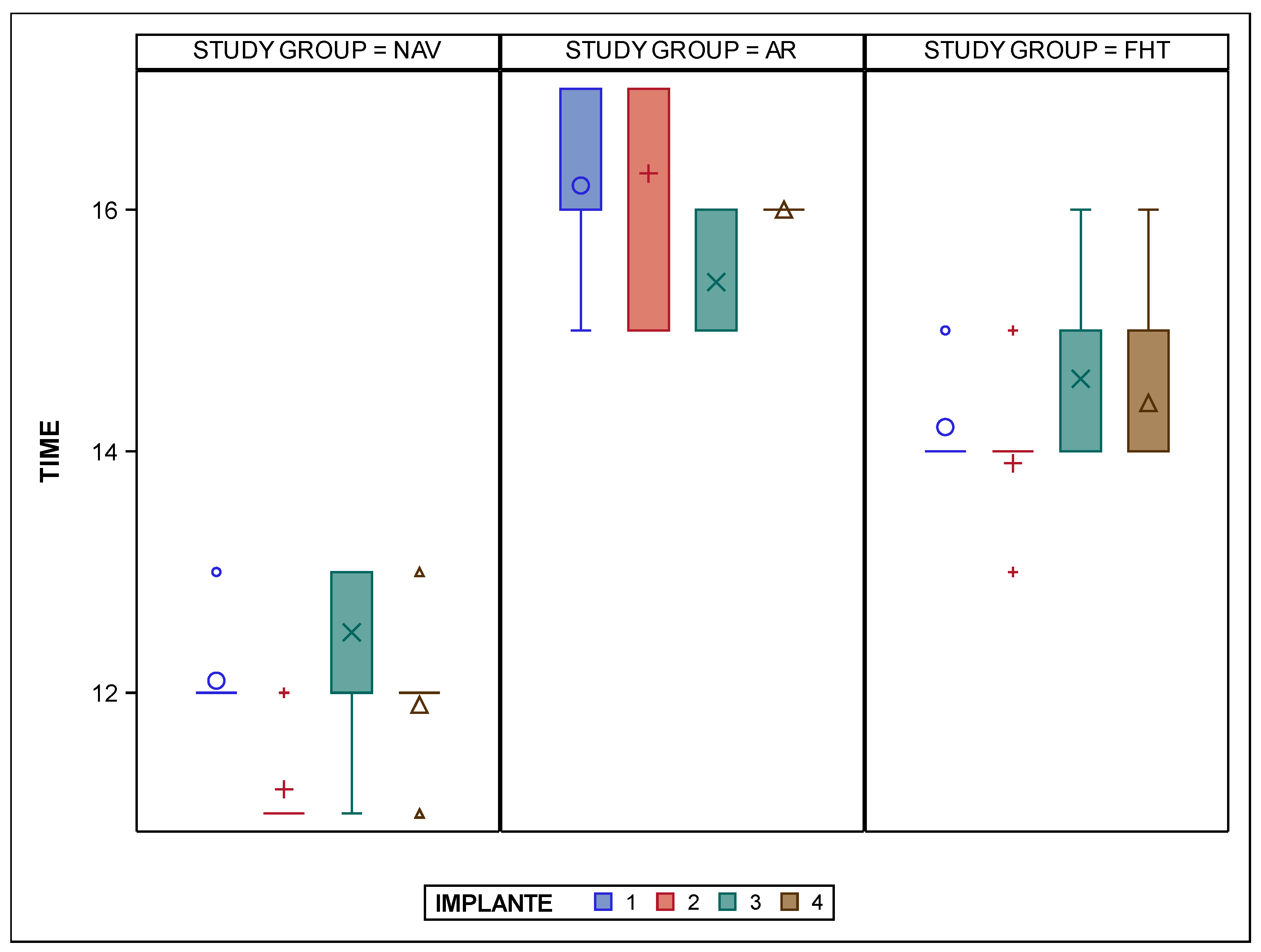
| Study Group | IOI | n | Mean | SD | Median | Minimum | Maximum |
|---|---|---|---|---|---|---|---|
| NAV | 1 | 10 | 12.10 | 0.32 | 12.00 | 12.00 | 13.00 |
| 2 | 10 | 11.20 | 0.42 | 11.00 | 11.00 | 12.00 | |
| 3 | 10 | 12.50 | 0.85 | 13.00 | 11.00 | 13.00 | |
| 4 | 10 | 11.90 | 0.57 | 12.00 | 11.00 | 13.00 | |
| AR | 1 | 10 | 16.20 | 0.63 | 16.00 | 15.00 | 17.00 |
| 2 | 10 | 16.30 | 0.95 | 17.00 | 15.00 | 17.00 | |
| 3 | 10 | 15.40 | 0.52 | 15.00 | 15.00 | 16.00 | |
| 4 | 10 | 16.00 | 0.00 | 16.00 | 16.00 | 16.00 | |
| FHT | 1 | 10 | 14.20 | 0.42 | 14.00 | 14.00 | 15.00 |
| 2 | 10 | 13.90 | 0.57 | 14.00 | 13.00 | 15.00 | |
| 3 | 10 | 14.60 | 0.84 | 14.00 | 14.00 | 16.00 | |
| 4 | 10 | 14.40 | 0.70 | 14.00 | 14.00 | 16.00 |
Disclaimer/Publisher’s Note: The statements, opinions and data contained in all publications are solely those of the individual author(s) and contributor(s) and not of MDPI and/or the editor(s). MDPI and/or the editor(s) disclaim responsibility for any injury to people or property resulting from any ideas, methods, instructions or products referred to in the content. |
© 2025 by the authors. Licensee MDPI, Basel, Switzerland. This article is an open access article distributed under the terms and conditions of the Creative Commons Attribution (CC BY) license (https://creativecommons.org/licenses/by/4.0/).
Share and Cite
Giovannini Riso, G.; Flores-Fraile, J.; Perrone, G.; Tzironi, G.; Galindo, A.B.L.; Galletti, C.; Zubizarreta-Macho, Á. Evaluation of Computer-Aided Navigation and Augmented Reality for Bicortical Mini-Implant Placement in Maxillary Expansion: An In Vitro Study. Bioengineering 2025, 12, 703. https://doi.org/10.3390/bioengineering12070703
Giovannini Riso G, Flores-Fraile J, Perrone G, Tzironi G, Galindo ABL, Galletti C, Zubizarreta-Macho Á. Evaluation of Computer-Aided Navigation and Augmented Reality for Bicortical Mini-Implant Placement in Maxillary Expansion: An In Vitro Study. Bioengineering. 2025; 12(7):703. https://doi.org/10.3390/bioengineering12070703
Chicago/Turabian StyleGiovannini Riso, Giovanni, Javier Flores-Fraile, Gianmarco Perrone, Georgia Tzironi, Ana Belén Lobo Galindo, Cosimo Galletti, and Álvaro Zubizarreta-Macho. 2025. "Evaluation of Computer-Aided Navigation and Augmented Reality for Bicortical Mini-Implant Placement in Maxillary Expansion: An In Vitro Study" Bioengineering 12, no. 7: 703. https://doi.org/10.3390/bioengineering12070703
APA StyleGiovannini Riso, G., Flores-Fraile, J., Perrone, G., Tzironi, G., Galindo, A. B. L., Galletti, C., & Zubizarreta-Macho, Á. (2025). Evaluation of Computer-Aided Navigation and Augmented Reality for Bicortical Mini-Implant Placement in Maxillary Expansion: An In Vitro Study. Bioengineering, 12(7), 703. https://doi.org/10.3390/bioengineering12070703