
Safety of Simultaneous Scalp and Intracranial EEG and fMRI: Evaluation of RF-Induced Heating

 , , and
Abstract
1. Introduction
2. Methods
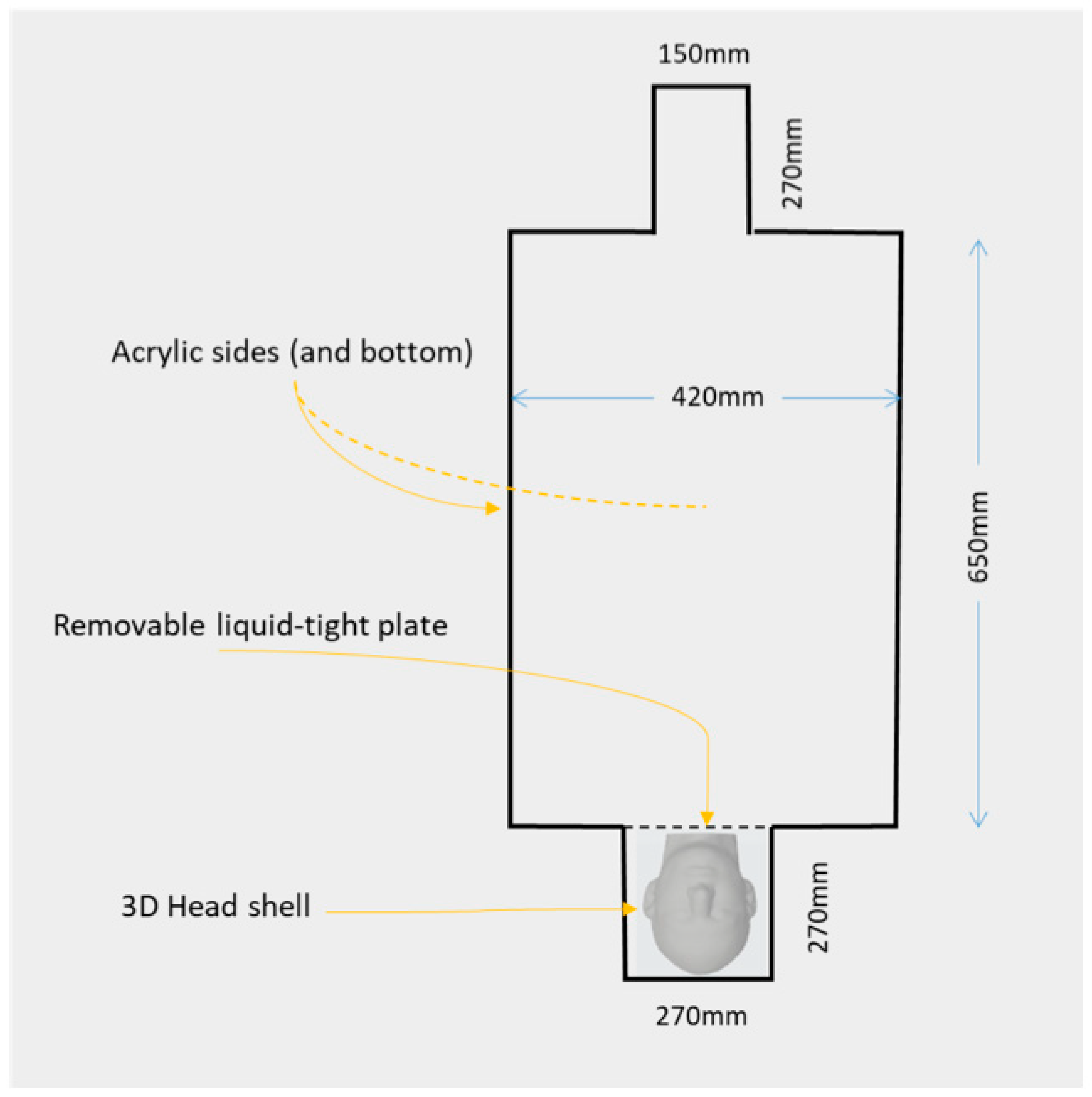
2.1. Combined QS-ASTM-II and Realistically Shaped Head Phantom
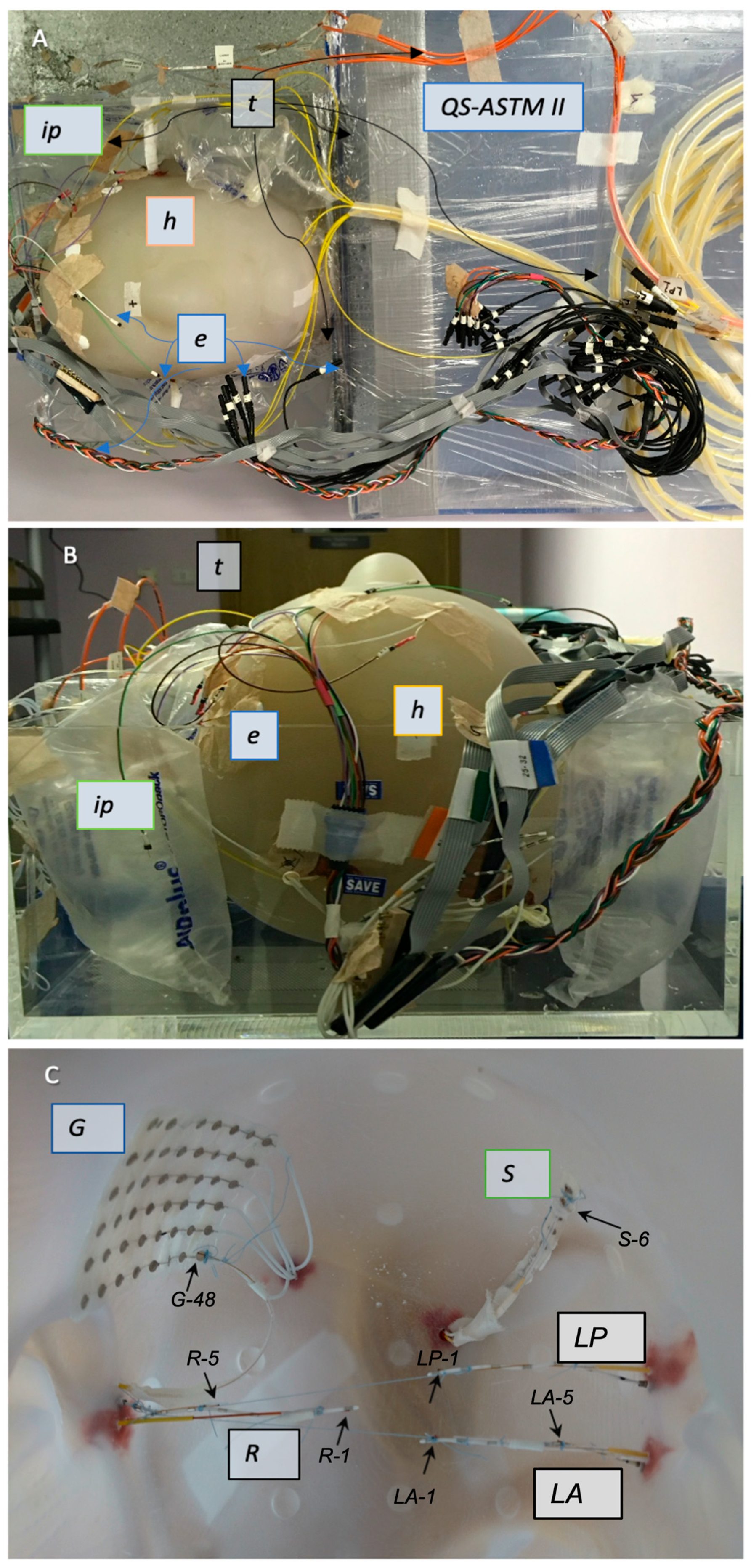
2.2. Electrode Description and Placement
2.2.1. IcEEG Electrodes—Experiment 1
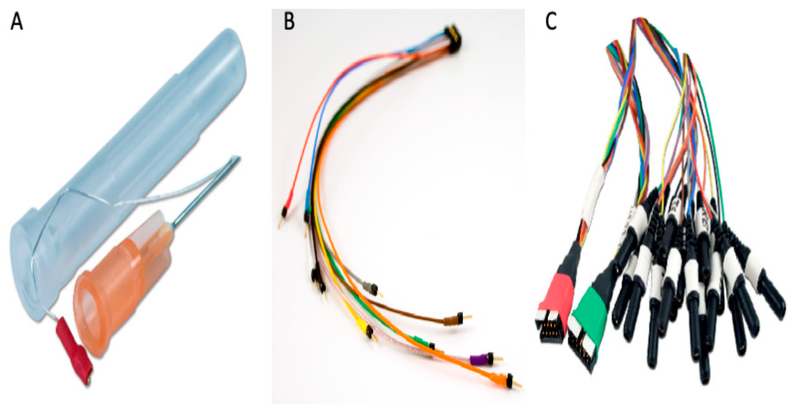
2.2.2. Subdermal Scalp EEG Electrodes—Experiment 2
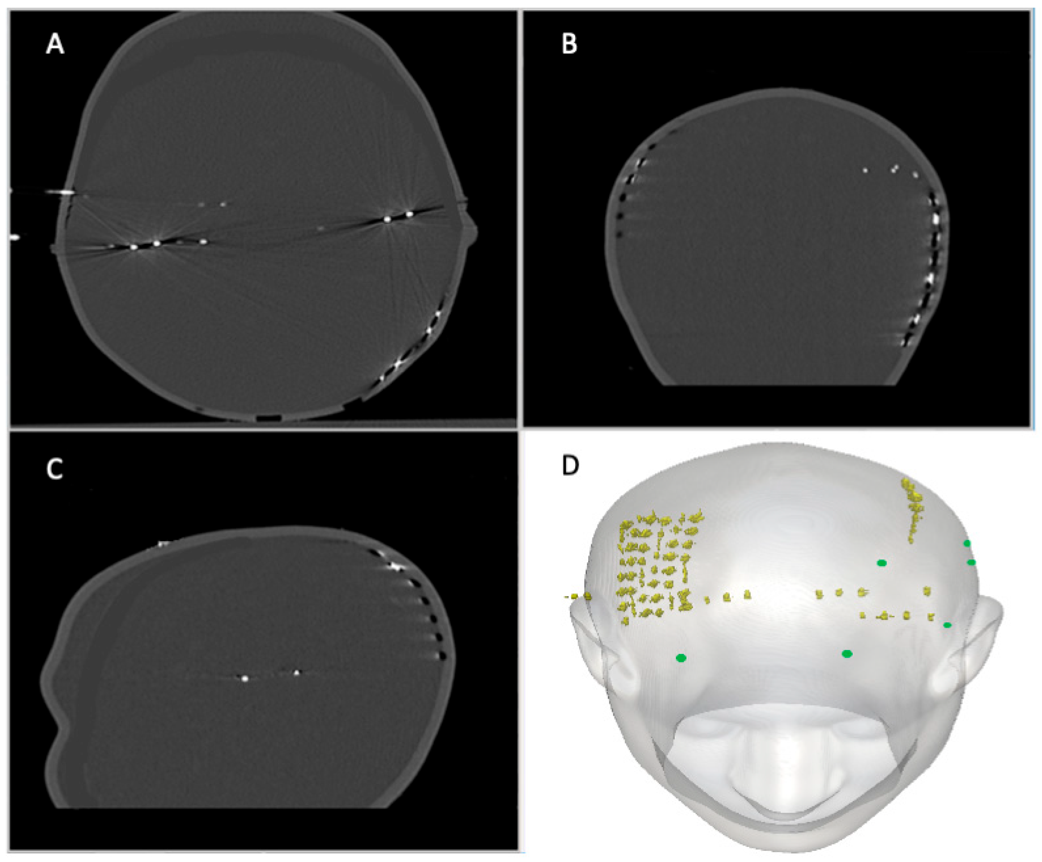
2.3. Temperature Probes
2.3.1. Experiment 1: Description
2.3.2. Experiment 2: Description
2.4. RF Exposure Protocol and Temperature Measurements
3. Results
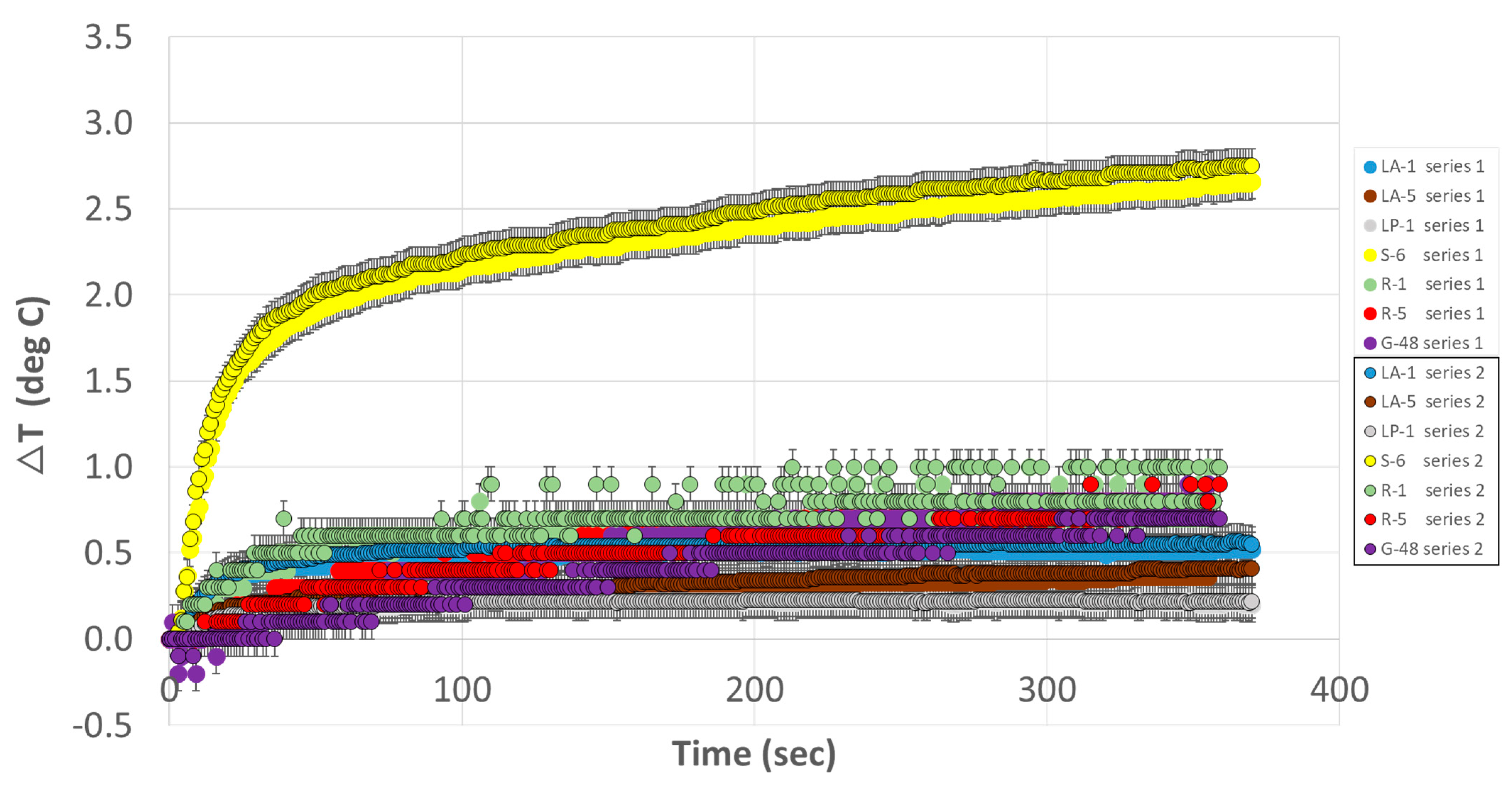
3.1. Experiment 1
3.2. Experiment 2
4. Discussion
4.1. Methodological Considerations
4.2. Choice of Subdermal Scalp Electrodes
4.3. Limitations of This Work
5. Conclusions
Author Contributions
Funding
Institutional Review Board Statement
Informed Consent Statement
Data Availability Statement
Acknowledgments
Conflicts of Interest
References
- Halgren, E.; Marinkovic, K.; Chauvel, P. Generators of the Late Cognitive Potentials in Auditory and Visual Oddball Tasks. Electroencephalogr. Clin. Neurophysiol. 1998, 106, 156–164. [Google Scholar] [CrossRef] [PubMed]
- Laufs, H.; Duncan, J.S. Electroencephalography/Functional MRI in Human Epilepsy: What It Currently Can and Cannot Do. Curr. Opin. Neurol. 2007, 20, 417–423. [Google Scholar] [CrossRef]
- Gavaret, M.; Trébuchon, A.; Bartolomei, F.; Marquis, P.; McGonigal, A.; Wendling, F.; Regis, J.; Badier, J.M.; Chauvel, P. Source Localization of Scalp-EEG Interictal Spikes in Posterior Cortex Epilepsies Investigated by HR-EEG and SEEG. Epilepsia 2009, 50, 276–289. [Google Scholar] [CrossRef]
- Ray, A.; Tao, J.X.; Hawes-Ebersole, S.M.; Ebersole, J.S. Localizing Value of Scalp EEG Spikes: A Simultaneous Scalp and Intracranial Study. Clin. Neurophysiol. 2007, 118, 69–79. [Google Scholar] [CrossRef] [PubMed]
- Lachaux, J.P.; Rudrauf, D.; Kahane, P. Intracranial EEG and Human Brain Mapping. J. Physiol. Paris. 2003, 97, 613–628. [Google Scholar] [CrossRef]
- Carmichael, D.W.; Thornton, J.S.; Rodionov, R.; Thornton, R.; McEvoy, A.W.; Ordidge, R.J.; Allen, P.J.; Lemieux, L. Feasibility of Simultaneous Intracranial EEG-FMRI in Humans: A Safety Study. Neuroimage 2010, 49, 379–390. [Google Scholar] [CrossRef]
- Tao, J.X.; Ray, A.; Hawes-ebersole, S.; Ebersole, J.S. Intracranial EEG Substrates of Scalp EEG Interictal Spikes. Epilepsia 2005, 46, 669–676. [Google Scholar] [CrossRef] [PubMed]
- Tao, J.X.; Baldwin, M.; Hawes-Ebersole, S.; Ebersole, J.S. Cortical Substrates of Scalp EEG Epileptiform Discharges. J. Clin. Neurophysiol. 2007, 24, 96–100. [Google Scholar] [CrossRef]
- Debatisse, D.; Pralong, E.; Dehdashti, A.R.; Regli, L. Simultaneous Multilobar Electrocorticography (MEcoG) and Scalp Electroencephalography (Scalp EEG) during Intracranial Vascular Surgery: A New Approach in Neuromonitoring. Clin. Neurophysiol. 2005, 116, 2734–2740. [Google Scholar] [CrossRef]
- Schad, A.; Schelter, B.; Maiwald, T.; Schulze-Bonhage, A.; Schindler, K.; Timmer, J.; Brandt, A. Application of a Multivariate Seizure Detection and Prediction Method to Non-Invasive and Intracranial Long-Term EEG Recordings. Clin. Neurophysiol. 2007, 119, 197–211. [Google Scholar] [CrossRef]
- Ramantani, G.; Dümpelmann, M.; Koessler, L.; Brandt, A.; Cosandier-Rimélé, D.; Zentner, J.; Schulze-Bonhage, A.; Maillard, L.G. Simultaneous Subdural and Scalp EEG Correlates of Frontal Lobe Epileptic Sources. Epilepsia 2014, 55, 278–288. [Google Scholar] [CrossRef] [PubMed]
- Burnos, S.; Sarnthein, J.; Krayenbühl, N.; Schmid, O.; Fedele, T. Detectability of the Somatosensory Evoked High Frequency Oscillation (HFO) Co-Recorded by Scalp EEG and ECoG under Propofol. Neuroimage Clin. 2015, 10, 318–325. [Google Scholar] [CrossRef] [PubMed]
- Cosandier-Rimélé, D.; Bartolomei, F.; Merlet, I.; Chauvel, P.; Wendling, F. Recording of Fast Activity at the Onset of Partial Seizures: Depth EEG vs. Scalp EEG. Neuroimage 2012, 59, 3474–3487. [Google Scholar] [CrossRef]
- Hosseini, S.A.H.; Sohrabpour, A.; He, B. Electromagnetic Source Imaging Using Simultaneous Scalp EEG and Intracranial EEG: An Emerging Tool for Interacting with Pathological Brain Networks. Clin. Neurophysiol. 2018, 129, 168–187. [Google Scholar] [CrossRef] [PubMed]
- Lanfer, B.; Röer, C.; Scherg, M.; Rampp, S.; Kellinghaus, C.; Wolters, C. Influence of a Silastic ECoG Grid on EEG/ECoG Based Source Analysis. Brain Topogr. 2013, 26, 212–228. [Google Scholar] [CrossRef]
- Dubarry, A.S.; Badier, J.M.; Trébuchon-Da Fonseca, A.; Gavaret, M.; Carron, R.; Bartolomei, F.; Liégeois-Chauvel, C.; Régis, J.; Chauvel, P.; Alario, F.X.; et al. Simultaneous Recording of MEG, EEG and Intracerebral EEG during Visual Stimulation: From Feasibility to Single-Trial Analysis. Neuroimage 2014, 99, 548–558. [Google Scholar] [CrossRef]
- Vulliemoz, S.; Lemieux, L.; Daunizeau, J.; Michel, C.M.; Duncan, J.S. The Combination of EEG Source Imaging and EEG-Correlated Functional MRI to Map Epileptic Networks. Epilepsia 2010, 51, 491–505. [Google Scholar] [CrossRef]
- Abreu, R.; Leal, A.; Figueiredo, P. EEG-Informed FMRI: A Review of Data Analysis Methods. Front. Hum. Neurosci. 2018, 12, 29. [Google Scholar] [CrossRef]
- Kowalczyk, M.A.; Omidvarnia, A.; Abbott, D.F.; Tailby, C.; Vaughan, D.N.; Jackson, G.D. Clinical Benefit of Presurgical EEG-FMRI in Difficult-to-Localize Focal Epilepsy: A Single-Institution Retrospective Review. Epilepsia 2020, 61, 49–60. [Google Scholar] [CrossRef]
- Hawsawi, H.B.; Carmichael, D.W.; Lemieux, L. Safety of Simultaneous Scalp or Intracranial EEG during MRI: A Review. Front. Phys. 2017, 5, 42. [Google Scholar] [CrossRef]
- Mirsattari, S.M.; Lee, D.H.; Jones, D.; Bihari, F.; Ives, J.R. MRI Compatible EEG Electrode System for Routine Use in the Epilepsy Monitoring Unit and Intensive Care Unit. Clin. Neurophysiol. 2004, 115, 2175–2180. [Google Scholar] [CrossRef] [PubMed]
- Mullinger, K.; Brookes, M.; Stevenson, C.; Morgan, P.; Bowtell, R. Exploring the Feasibility of Simultaneous Electroencephalography/Functional Magnetic Resonance Imaging at 7 T. Magn. Reson. Imaging 2008, 26, 968–977. [Google Scholar] [CrossRef] [PubMed]
- Jorge, J.; Grouiller, F.; Ipek, Ö.; Stoermer, R.; Michel, C.M.; Figueiredo, P.; Van Der Zwaag, W.; Gruetter, R. Simultaneous EEG-FMRI at Ultra-High Field: Artifact Prevention and Safety Assessment. Neuroimage 2015, 105, 132–144. [Google Scholar] [CrossRef] [PubMed]
- Assecondi, S.; Lavallee, C.; Ferrari, P.; Jovicich, J. Length Matters: Improved High Field EEG-FMRI Recordings Using Shorter EEG Cables. J. Neurosci. Methods 2016, 269, 74–87. [Google Scholar] [CrossRef]
- Bonmassar, G.; Anami, K.; Belliveau, J.W. Improved Subject’s Safety in Simultaneous EEG and FMRI Recordings Using Solid State Switching Devices on the Electrodes. In Proceedings of the First Joint BMES/EMBS Conference, Atlanta, GA, USA, 13–16 October 1999. [Google Scholar]
- Vasios, C.E.; Angelone, L.M.; Purdon, P.L.; Ahveninen, J.; Belliveau, J.W.; Bonmassar, G. EEG/(f)MRI Measurements at 7 Tesla Using a New EEG Cap (“InkCap”). Neuroimage 2006, 33, 1082–1092. [Google Scholar] [CrossRef]
- Stevens, T.K.; Ives, J.R.; Klassen, L.M.; Bartha, R. MR Compatibility of EEG Scalp Electrodes at 4 Tesla. J. Magn. Reson. Imaging 2007, 25, 872–877. [Google Scholar] [CrossRef]
- Kuusela, L.; Turunen, S.; Valanne, L.; Sipilä, O. Safety in Simultaneous EEG-FMRI at 3 T: Temperature Measurements. Acta Radiol. 2015, 56, 739–745. [Google Scholar] [CrossRef]
- Poulsen, C.; Wakeman, D.G.; Atefi, S.R.; Luu, P.; Konyn, A.; Bonmassar, G. Polymer Thick Film Technology for Improved Simultaneous DEEG/MRI Recording: Safety and MRI Data Quality. Magn. Reson. Med. 2017, 77, 895–903. [Google Scholar] [CrossRef]
- Balasubramanian, M.; Wells, W.M.; Ives, J.R.; Britz, P.; Mulkern, R.V.; Orbach, D.B. RF Heating of Gold Cup and Conductive Plastic Electrodes during Simultaneous EEG and MRI. Neurodiagn J. 2017, 57, 69–83. [Google Scholar] [CrossRef]
- Angelone, L.M.; Vasios, C.E.; Wiggins, G.; Purdon, P.L.; Bonmassar, G. On the Effect of Resistive EEG Electrodes and Leads during 7 T MRI: Simulation and Temperature Measurement Studies. Magn. Reson. Imaging 2006, 24, 801–812. [Google Scholar] [CrossRef]
- Lemieux, L.; Allen, P.J.; Franconi, F.; Symms, M.R.; Fish, D.R. Recording of EEG during FMRI Experiments: Patient Safety. Magn. Reson. Med. 1997, 38, 943–952. [Google Scholar] [CrossRef] [PubMed]
- Vulliemoz, S.; Diehl, B.; Walker, M.C.; Rosenkranz, K.; Rodionov, R.; McEvoy, A.W.; Carmichael, D.W.; Lemieux, L. Simultaneous Intracranial EEG and FMRI of Interictal Epileptic Discharges in Humans. Neuroimage 2011, 54, 182–190. [Google Scholar] [CrossRef]
- Cunningham, C.B.J.; Goodyear, B.G.; Badawy, R.; Zaamout, F.; Pittman, D.J.; Beers, C.A.; Federico, P. Intracranial EEG-FMRI Analysis of Focal Epileptiform Discharges in Humans. Epilepsia 2012, 53, 1636–1648. [Google Scholar] [CrossRef]
- Saignavongs, M.; Ciumas, C.; Petton, M.; Bouet, R.; Boulogne, S.; Rheims, S.; Carmichael, D.W.; Lachaux, J.-P.; Ryvlin, P. Neural Activity Elicited by a Cognitive Task Can Be Detected in Single-Trials with Simultaneous Intracerebral EEG-FMRI Recordings. Int. J. Neural Syst. 2017, 27, 1750001. [Google Scholar] [CrossRef] [PubMed]
- Zhang, J.; Wilson, C.L.; Levesque, M.F.; Behnke, E.J.; Lufkin, R.B. Temperature Changes in Nickel-Chromium Intracranial Depth Electrodes during MR Scanning. AJNR Am. J. Neuroradiol. 1993, 14, 497–500. [Google Scholar] [PubMed]
- Ciumas, C.; Canet-Soulas, E.; Ryvlin, P.; Schaefers, G.; Bouvard, S.; Comte, J.-C.; Moya, J.; Perrin, E.; Tailhades, E.; Bonnet, C.; et al. A Phantom and Animal Study of Temperature Changes during FMRI with Intracerebral Depth Electrodes. Epilepsy Res. 2013, 108, 57–65. [Google Scholar] [CrossRef]
- Boucousis, S.M.; Beers, C.A.; Cunningham, C.J.B.; Gaxiola-Valdez, I.; Pittman, D.J.; Goodyear, B.G.; Federico, P. Feasibility of an Intracranial EEG–FMRI Protocol at 3 T: Risk Assessment and Image Quality. Neuroimage 2012, 63, 1237–1248. [Google Scholar] [CrossRef]
- Bhattacharyya, P.K.; Mullin, J.; Lee, B.S.; Gonzalez-Martinez, J.A.; Jones, S.E. Safety of Externally Stimulated Intracranial Electrodes during Functional MRI at 1.5 T. Magn. Reson. Imaging 2017, 38, 182–188. [Google Scholar] [CrossRef]
- Bhusal, B.; Bhattacharyya, P.; Baig, T.; Jones, S.; Martens, M. Measurements and Simulation of RF Heating of Implanted Stereo-Electroencephalography Electrodes during MR Scans. Magn. Reson. Med. 2018, 80, 1676–1685. [Google Scholar] [CrossRef]
- Hawsawi, H.B.; Papadaki, A.; Thornton, J.S.; Carmichael, D.W.; Lemieux, L. Temperature Measurements in the Vicinity of Human Intracranial EEG Electrodes Exposed to Body-Coil RF for MRI at 1.5 T. Front. Neurosci. 2020, 14, 429. [Google Scholar] [CrossRef]
- Carmichael, D.W.; Thornton, J.S.; Rodionov, R.; Thornton, R.; McEvoy, A.; Allen, P.J.; Lemieux, L. Safety of Localizing Epilepsy Monitoring Intracranial Electroencephalograph Electrodes Using MRI: Radiofrequency-Induced Heating. J. Magn. Reson. Imaging 2008, 28, 1233–1244. [Google Scholar] [CrossRef] [PubMed]
- Liu, J.Y.W.; Hawsawi, H.B.; Sharma, N.K.; Carmichael, D.W.; Diehl, B.; Thom, M.; Lemieux, L. Safety of Intracranial Electroencephalography during Functional Magnetic Resmonance Imaging in Humans: Histopathological and Heatshock Immunohistochemistry Observations. Neuroimage 2022, 254. [Google Scholar] [CrossRef]
- Ives, J.R. New Chronic EEG Electrode for Critical/Intensive Care Unit Monitoring. J. Clin. Neurophysiol. 2005, 22, 119–123. [Google Scholar] [CrossRef]
- Young, G.B.; Ives, J.R.; Chapman, M.G.; Mirsattari, S.M. A Comparison of Subdermal Wire Electrodes with Collodion-Applied Disk Electrodes in Long-Term EEG Recordings in ICU. Clin. Neurophysiol. 2006, 117, 1376–1379. [Google Scholar] [CrossRef]
- Martz, G.U.; Hucek, C.; Quigg, M. Sixty Day Continuous Use of Subdermal Wire Electrodes for Eeg Monitoring during Treatment of Status Epilepticus. Neurocrit. Care 2009, 11, 223–227. [Google Scholar] [CrossRef]
- Darcey, T.M.; Kobylarz, E.J.; Pearl, M.A.; Krauss, P.J.; Ferri, S.A.; Roberts, D.W.; Bauer, D.F. Safe Use of Subdermal Needles for Intraoperative Monitoring with MRI. Neurosurg. Focus. 2016, 40, E19. [Google Scholar] [CrossRef] [PubMed]
- Rezai, A.R.; Finelli, D.; Nyenhuis, J.A.; Hrdlicka, G.; Tkach, J.; Sharan, A.; Rugieri, P.; Stypulkowski, P.H.; Shellock, F.G. Neurostimulation Systems for Deep Brain Stimulation: In Vitro Evaluation of Magnetic Resonance Imaging-Related Heating at 1.5 Tesla. J. Magn. Reson. Imaging 2002, 15, 241–250. [Google Scholar] [CrossRef]
- Finelli, D.A.; Rezai, A.R.; Ruggieri, P.; Tkach, J.; Nyenhuis, J.; Hridlicka, G.; Sharan, A.; Gonzalez-Martinez, J.; Stypulkowski, P.H.; Shellock, F.G. MR-Related Heating of Deep Brain Stimulation Electrodes: An in Vitro Study of Clinical Imaging Sequences. Am. J. Neuroradiol. 2002, 23, 1795–1802. [Google Scholar] [PubMed]
- Baker, K.B.; Tkach, J.; Hall, J.D.; Nyenhuis, J.A.; Shellock, F.G.; Rezai, A.R. Reduction of Magnetic Resonance Imaging-Related Heating in Deep Brain Stimulation Leads Using a Lead Management Device. Oper. Neurosurg. 2005, 57, ONS-392–ONS-397. [Google Scholar] [CrossRef]
- Baker, K.B.; Tkach, J.A.; Nyenhuis, J.A.; Phillips, M.; Shellock, F.G.; Gonzalez-Martinez, J.; Rezai, A.R. Evaluation of Specific Absorption Rate as a Dosimeter of MRI-Related Implant Heating. J. Magn. Reson. Imaging 2004, 20, 315–320. [Google Scholar] [CrossRef]
- Carmichael, D.W.; Pinto, S.; Limousin-Dowsey, P.; Thobois, S.; Allen, P.J.; Lemieux, L.; Yousry, T.; Thornton, J.S. Functional MRI with Active, Fully Implanted, Deep Brain Stimulation Systems: Safety and Experimental Confounds. Neuroimage 2007, 37, 508–517. [Google Scholar] [CrossRef] [PubMed]
- Kahan, J.; Papadaki, A.; White, M.; Mancini, L.; Yousry, T.; Zrinzo, L.; Limousin, P.; Hariz, M.; Foltynie, T.; Thornton, J. The Safety of Using Body-Transmit MRI in Patients with Implanted Deep Brain Stimulation Devices. PLoS ONE 2015, 10, e0129077. [Google Scholar] [CrossRef] [PubMed]
- Sammartino, F.; Krishna, V.; Sankar, T.; Fisico, J.; Kalia, S.K.; Hodaie, M.; Kucharczyk, W.; Mikulis, D.J.; Crawley, A.; Lozano, A.M. 3-Tesla MRI in Patients with Fully Implanted Deep Brain Stimulation Devices: A Preliminary Study in 10 Patients. J. Neurosurg. 2017, 127, 892–898. [Google Scholar] [CrossRef]
- ASTM Standard F2182-19ε2; Standard Test Method for Measurement of Radio Frequency Induced Heating Near Passive Implants During Magnetic Resonance Imaging. ASTM: West Conshohocke, PA, USA, 2020; pp. 1–14. [CrossRef]
- Park, S.M.; Sharan, A.; Baker, K.B.; Rezai, A.R.; Smith, C.D.; Shellock, F.G.; Tkach, J.; Lim, E.J.; Nyenhuis, J.A.; Stypulkowski, P.H.; et al. Gelled versus Nongelled Phantom Material for Measurement of MRI-Induced Temperature Increases with Bioimplants. IEEE Trans. Magn. 2003, 39, 3367–3371. [Google Scholar] [CrossRef]
- Jasper, H.H. The Ten-Twenty Electrode System of the International Federation. Electroencephalogr. Clin. Neurophysiol. 1958, 10, 370–375. [Google Scholar]
- Yan, W.X.; Mullinger, K.J.; Brookes, M.J.; Bowtell, R. Understanding Gradient Artefacts in Simultaneous EEG/FMRI. Neuroimage 2009, 46, 459–471. [Google Scholar] [CrossRef] [PubMed]
- Nowell, M.; Rodionov, R.; Diehl, B.; Wehner, T.; Zombori, G.; Kinghorn, J.; Ourselin, S.; Duncan, J.; Miserocchi, A.; McEvoy, A. A Novel Method for Implementation of Frameless StereoEEG in Epilepsy Surgery. Oper. Neurosurg. 2014, 10, 525–533. [Google Scholar] [CrossRef]
- Vakharia, V.N.; Miserocchi, A.; McEvoy, A.W.; Rodionov, R.; Ourselin, S.; Sparks, R.; Duncan, J.S.; O’Keeffe, A.G. Improving Patient Safety during Introduction of Novel Medical Devices through Cumulative Summation Analysis. J. Neurosurg. 2018, 130, 213–219. [Google Scholar] [CrossRef]
- Carmichael, D.W.; Vulliemoz, S.; Rodionov, R.; Thornton, J.S.; Mcevoy, A.W.; Lemieux, L. Simultaneous Intracranial EEG–FMRI in Humans: Protocol Considerations and Data Quality. Neuroimage 2012, 63, 301–309. [Google Scholar] [CrossRef]
- Nöth, U.; Laufs, H.; Stoermer, R.; Deichmann, R. Simultaneous Electroencephalography-Functional MRI at 3 T: An Analysis of Safety Risks Imposed by Performing Anatomical Reference Scans with the EEG Equipment in Place. J. Magn. Reson. Imaging 2012, 35, 561–571. [Google Scholar] [CrossRef]
- Mattei, E.; Calcagnini, G.; Triventi, M.; Censi, F.; Bartolini, P.; Kainz, W.; Bassen, H. MRI Induced Heating of Pacemaker Leads: Effect of Temperature Probe Positioning and Pacemaker Placement on Lead Tip Heating and Local SAR. In Proceedings of the 2006 International Conference of the IEEE Engineering in Medicine and Biology Society, New York, NY, USA, 30 August–3 September 2006; pp. 1889–1892. [Google Scholar]
- Mullinger, K.J.; Yan, W.X.; Bowtell, R. Reducing the Gradient Artefact in Simultaneous EEG-FMRI by Adjusting the Subject’s Axial Position. Neuroimage 2011, 54, 1942–1950. [Google Scholar] [CrossRef] [PubMed]
- Bullock, M.; Jackson, G.D.; Abbott, D.F. Artifact Reduction in Simultaneous EEG-FMRI: A Systematic Review of Methods and Contemporary Usage. Front. Neurol. 2021, 12, 622719. [Google Scholar] [CrossRef] [PubMed]
- Murta, T.; Chaudhary, U.J.; Tierney, T.M.; Dias, A.; Leite, M.; Carmichael, D.W.; Figueiredo, P.; Lemieux, L. Phase–Amplitude Coupling and the BOLD Signal: A Simultaneous Intracranial EEG (IcEEG)—FMRI Study in Humans Performing a Finger-Tapping Task. Neuroimage 2017, 146, 438–451. [Google Scholar] [CrossRef] [PubMed]
- Sharma, N.K.; Pedreira, C.; Chaudhary, U.J.; Centeno, M.; Carmichael, D.W.; Yadee, T.; Murta, T.; Diehl, B.; Lemieux, L. NeuroImage BOLD Mapping of Human Epileptic Spikes Recorded during Simultaneous Intracranial EEG-FMRI: The Impact of Automated Spike Classi Fi Cation. Neuroimage 2019, 184, 981–992. [Google Scholar] [CrossRef]
- Ridley, B.; Wirsich, J.; Bettus, G.; Rodionov, R.; Murta, T.; Chaudhary, U.; Carmichael, D.; Thornton, R.; Vulliemoz, S.; McEvoy, A.; et al. Simultaneous Intracranial EEG-FMRI Shows Inter-Modality Correlation in Time-Resolved Connectivity within Normal Areas but Not within Epileptic Regions. Brain Topogr. 2017, 30, 639–655. [Google Scholar] [CrossRef]
- IEC 60601-2-33:2022; Medical Electrical Equipment—Part 2-33: Particular Requirements for the Basic Safety and Essential Performance of Magnetic Resonance Equipment for Medical Diagnosis. International Electrotechnical Commission: Geneva, Switzerland, 2022. Available online: https://webstore.iec.ch/en/publication/67211 (accessed on 13 January 2025).
- Yeung, C.J.; Susil, R.C.; Atalar, E. RF Heating Due to Conductive Wires during MRI Depends on the Phase Distribution of the Transmit Field. Magn. Reson. Med. 2002, 48, 1096–1098. [Google Scholar] [CrossRef]
- Yeung, C.J.; Karmarkar, P.; McVeigh, E.R. Minimizing RF Heating of Conducting Wires in MRI. Magn. Reson. Med. 2007, 58, 1028–1034. [Google Scholar] [CrossRef]
- Konings, M.K.; Bartels, L.W.; Smits, H.F.M.; Bakker, C.J.G. Heating Around Intravascular Guidewires by Resonating RF Waves. J. Magn. Reson. Imaging 2000, 12, 79–85. [Google Scholar] [CrossRef]
- Georgi, J.C.; Stippich, C.; Tronnier, V.M.; Heiland, S. Active Deep Brain Stimulation during MRI: A Feasibility Study. Magn. Reson. Med. 2004, 51, 380–388. [Google Scholar] [CrossRef]
- Shrivastava, D.; Abosch, A.; Hanson, T.; Tian, J.; Gupte, A.; Iaizzo, P.A.; Vaughan, J.T. Effect of the Extracranial Deep Brain Stimulation Lead on Radiofrequency Heating at 9.4 Tesla (400.2 MHz). J. Magn. Reson. Imaging 2010, 32, 600–607. [Google Scholar] [CrossRef]
- Nyenhuis, J.A.; Kildishev, A.V.; Athey, T.W.; Bourland, J.D.; Foster, K.S.; Graber, G.P. Heating near Implanted Medical Devices by the MRI RF-Magnetic Field. Dig. Intermag Conf. 1999, 35, 16–18. [Google Scholar] [CrossRef]
- Shellock, F.G. Metallic Neurosurgical Implants: Evaluation of Magnetic Field Interactions, Heating, and Artifacts at 1.5-Tesla. J. Magn. Reson. Imaging 2001, 14, 295–299. [Google Scholar] [CrossRef]
- Eryaman, Y.; Akin, B.; Atalar, E. Reduction of Implant RF Heating through Modification of Transmit Coil Electric Field. Magn. Reson. Med. 2011, 65, 1305–1313. [Google Scholar] [CrossRef] [PubMed]
- Eryaman, Y.; Turk, E.A.; Oto, C.; Algin, O.; Atalar, E. Reduction of the Radiofrequency Heating of Metallic Devices Using a Dual-Drive Birdcage Coil. Magn. Reson. Med. 2013, 69, 845–852. [Google Scholar] [CrossRef] [PubMed]
- Ahmadi, E.; Katnani, H.A.; Besheli, L.D.; Gu, Q.; Atefi, R.; Villeneuve, M.Y.; Eskandar, E.; Lev, M.H.; Golby, A.J.; Gupta, R.; et al. An Electrocorticography Grid with Conductive Nanoparticles in a Polymer Thick Film on an Organic Substrate Improves CT and MR Imaging. Radiology 2016, 280, 595–601. [Google Scholar] [CrossRef]
- Kainz, W.; Neubauer, G.; Überbacher, R.; Alesch, F.; Chan, D.D. Temperature Measurement on Neurological Pulse Generators during MR Scans. Biomed. Eng. Online 2002, 1, 2. [Google Scholar] [CrossRef]
- Bland, J.M.; Altam, D.G. Comparing Methods of Measurement: Why Plotting Difference against Standard Method Is Misleading. Clin. Lab. Haematol. 1995, 346, 1085–1087. [Google Scholar] [CrossRef]
- Oya, H.; Howard, M.A.; Magnotta, V.A.; Kruger, A.; Griffiths, T.D.; Lemieux, L.; Carmichael, D.W.; Petkov, C.I.; Kawasaki, H.; Kovach, C.K.; et al. Mapping Effective Connectivity in the Human Brain with Concurrent Intracranial Electrical Stimulation and BOLD-FMRI. J. Neurosci. Methods 2017, 277, 101–112. [Google Scholar] [CrossRef]
- Chaudhary, U.J.; Centeno, M.; Carmichael, D.W.; Diehl, B.; Walker, M.C.; Duncan, J.S.; Lemieux, L. Mapping Epileptic Networks Using Simultaneous Intracranial EEG-FMRI. Front. Neurol. 2021, 12, 693504. [Google Scholar] [CrossRef]
- Sawada, M.; Adolphs, R.; Dlouhy, B.J.; Jenison, R.L.; Rhone, A.E.; Kovach, C.K.; Greenlee, D.W.J.; Howard, M.A., III; Oya, H. Mapping Effective Connectivity of Human Amygdala Subdivisions with Intracranial Stimulation. Nat. Commun. 2022, 13, 4909. [Google Scholar] [CrossRef]
- Wilson, W.; Tehrani, N.; Pittman, D.J.; Dykens, P.; Mosher, V.; Gill, L.; Peedicail, J.; George, A.G.; Beers, C.A.; Goodyear, B.; et al. Mapping Interictal Discharges Using Intracranial EEG-FMRI to Predict Postsurgical Outcomes. Brain 2024, 147, 4157–4168. [Google Scholar] [CrossRef] [PubMed]
- Hawsawi, H.B.; Allen, P.J.; Warbrick, T.; Störmer, R.; Iannotti, G.; Grouiller, F.; Vulliemoz, S.; Lemieux, L. EEG Instrumentation and Safety in the MRI Environment. In EEG—fMRI: Physiological Basis, Technique, and Applications; Mulert, C., Lemieux, L., Eds.; Springer: Cham, Switzerland, 2022; pp. 141–166. ISBN 978-3-031-07121-8. [Google Scholar]

| Series # | Location | Maximum Temperature Increase (°C) | |||||||
|---|---|---|---|---|---|---|---|---|---|
| MRI Sequence | icEEG Electrode Contact Label | ||||||||
| LA-1 | LA-5 | LP-1 | S-6 | R-1 | R-5 | G-48 | |||
| 1 | TSE | 0.5 | 0.4 | 0.2 | 2.7 | 1.0 | 0.8 | 0.9 | |
| 2 | TSE | 0.6 | 0.4 | 0.2 | 2.8 | 1.0 | 0.9 | 0.7 | |
| Series # | Location | Maximum Temperature Increase (°C) | |||||||||||
|---|---|---|---|---|---|---|---|---|---|---|---|---|---|
| MRI Sequence | icEEG Electrode Contact Label | Scalp Electrode Contact Label | |||||||||||
| LA-1 | LP-1 | S-6 | R-1 | R-5 | G-48 | F3 | FP1 | T5 | F7 | FP2 | |||
| 1 | TSE | 0.5 | 0.1 | 2.1 | 1.3 | 1.2 | 0.3 | 0.2 | 0.2 | 0.4 | 0.5 | 0.6 | |
| 2 | TSE | 0.6 | 0.1 | 1.7 | 1.2 | 0.9 | 0.4 | 0.2 | 0.3 | 0.4 | 0.3 | 0.6 | |
| 3 | EPI | <0.1 | <0.1 | <0.1 | <0.1 | <0.1 | <0.1 | <0.1 | 0.4 | 0.7 | 0.3 | 0.5 | |
Disclaimer/Publisher’s Note: The statements, opinions and data contained in all publications are solely those of the individual author(s) and contributor(s) and not of MDPI and/or the editor(s). MDPI and/or the editor(s) disclaim responsibility for any injury to people or property resulting from any ideas, methods, instructions or products referred to in the content. |
© 2025 by the authors. Licensee MDPI, Basel, Switzerland. This article is an open access article distributed under the terms and conditions of the Creative Commons Attribution (CC BY) license (https://creativecommons.org/licenses/by/4.0/).
Share and Cite
Hawsawi, H.B.; Papadaki, A.; Vakharia, V.N.; Thornton, J.S.; Carmichael, D.W.; Kumar, S.; Lemieux, L. Safety of Simultaneous Scalp and Intracranial EEG and fMRI: Evaluation of RF-Induced Heating. Bioengineering 2025, 12, 564. https://doi.org/10.3390/bioengineering12060564
Hawsawi HB, Papadaki A, Vakharia VN, Thornton JS, Carmichael DW, Kumar S, Lemieux L. Safety of Simultaneous Scalp and Intracranial EEG and fMRI: Evaluation of RF-Induced Heating. Bioengineering. 2025; 12(6):564. https://doi.org/10.3390/bioengineering12060564
Chicago/Turabian StyleHawsawi, Hassan B., Anastasia Papadaki, Vejay N. Vakharia, John S. Thornton, David W. Carmichael, Suchit Kumar, and Louis Lemieux. 2025. "Safety of Simultaneous Scalp and Intracranial EEG and fMRI: Evaluation of RF-Induced Heating" Bioengineering 12, no. 6: 564. https://doi.org/10.3390/bioengineering12060564
APA StyleHawsawi, H. B., Papadaki, A., Vakharia, V. N., Thornton, J. S., Carmichael, D. W., Kumar, S., & Lemieux, L. (2025). Safety of Simultaneous Scalp and Intracranial EEG and fMRI: Evaluation of RF-Induced Heating. Bioengineering, 12(6), 564. https://doi.org/10.3390/bioengineering12060564