


Comparative Biomechanical Analysis of Unilateral, Bilateral, and Lateral Pedicle Screw Implantation in Oblique Lumbar Interbody Fusion: A Finite Element Study

 , ,
, , 
Abstract
:1. Introduction
2. Materials and Methods
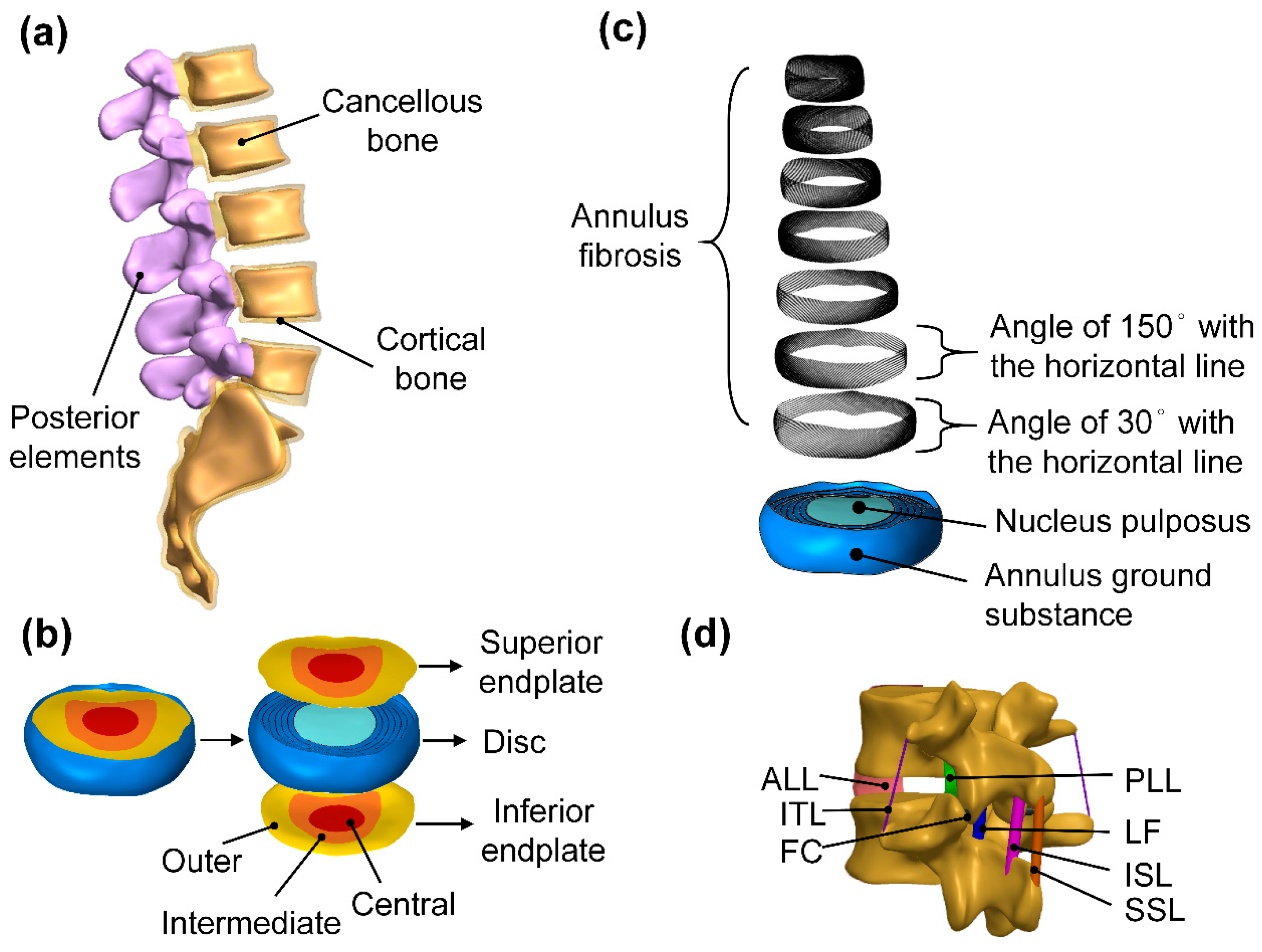
2.1. Simulation of Lumbar Geometry Model
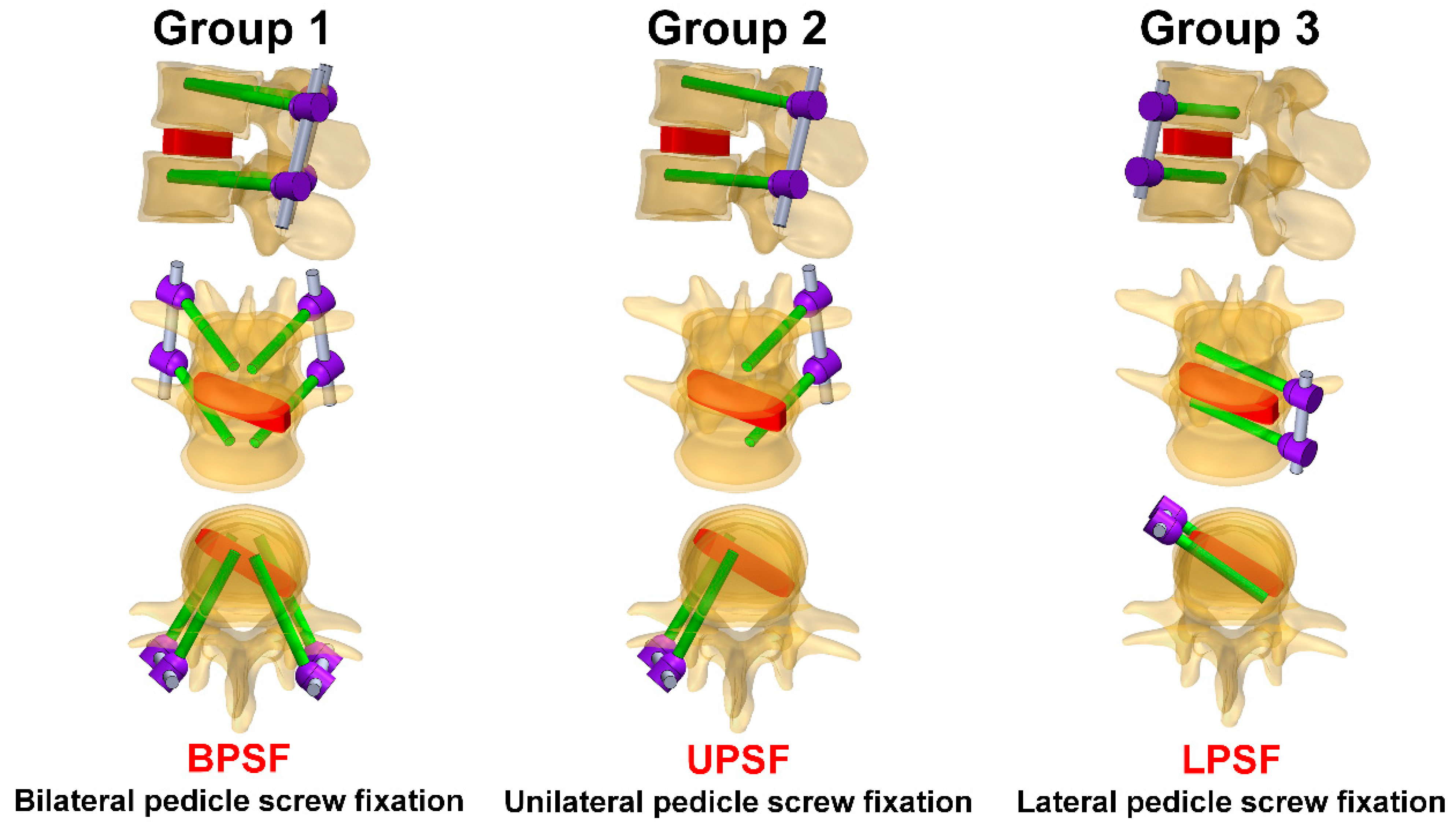
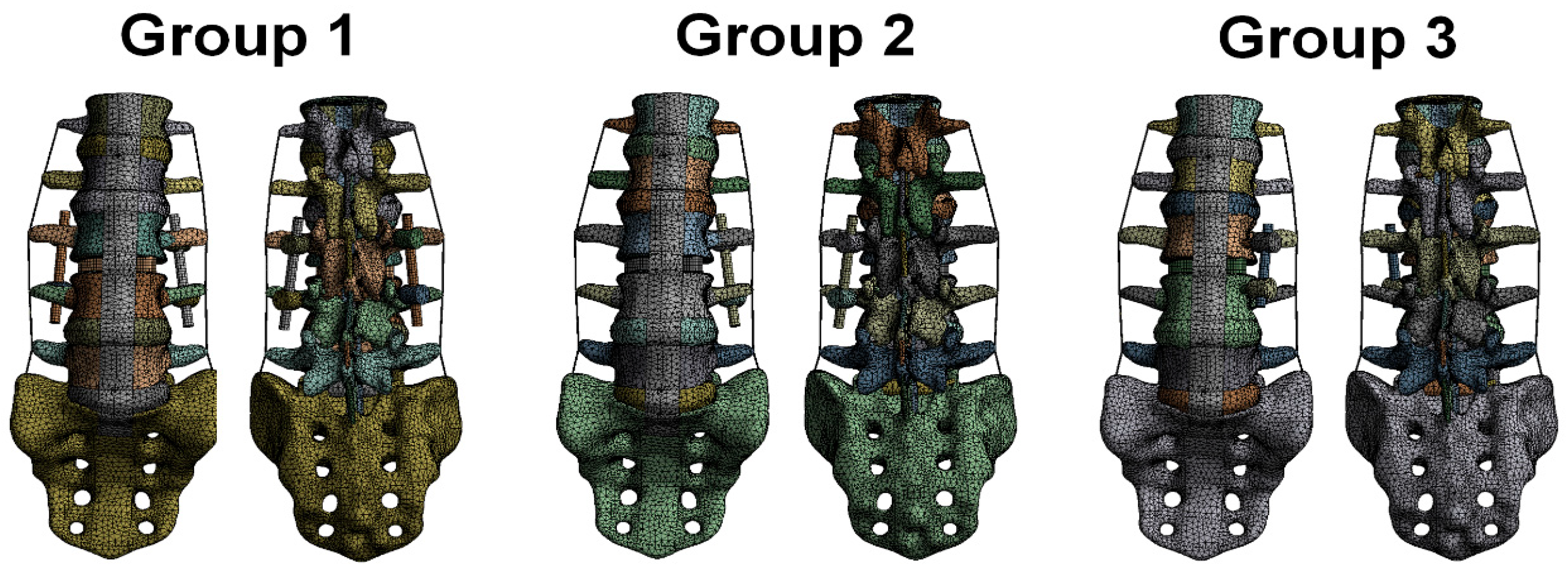
2.2. Different Pedicle Screw Systems
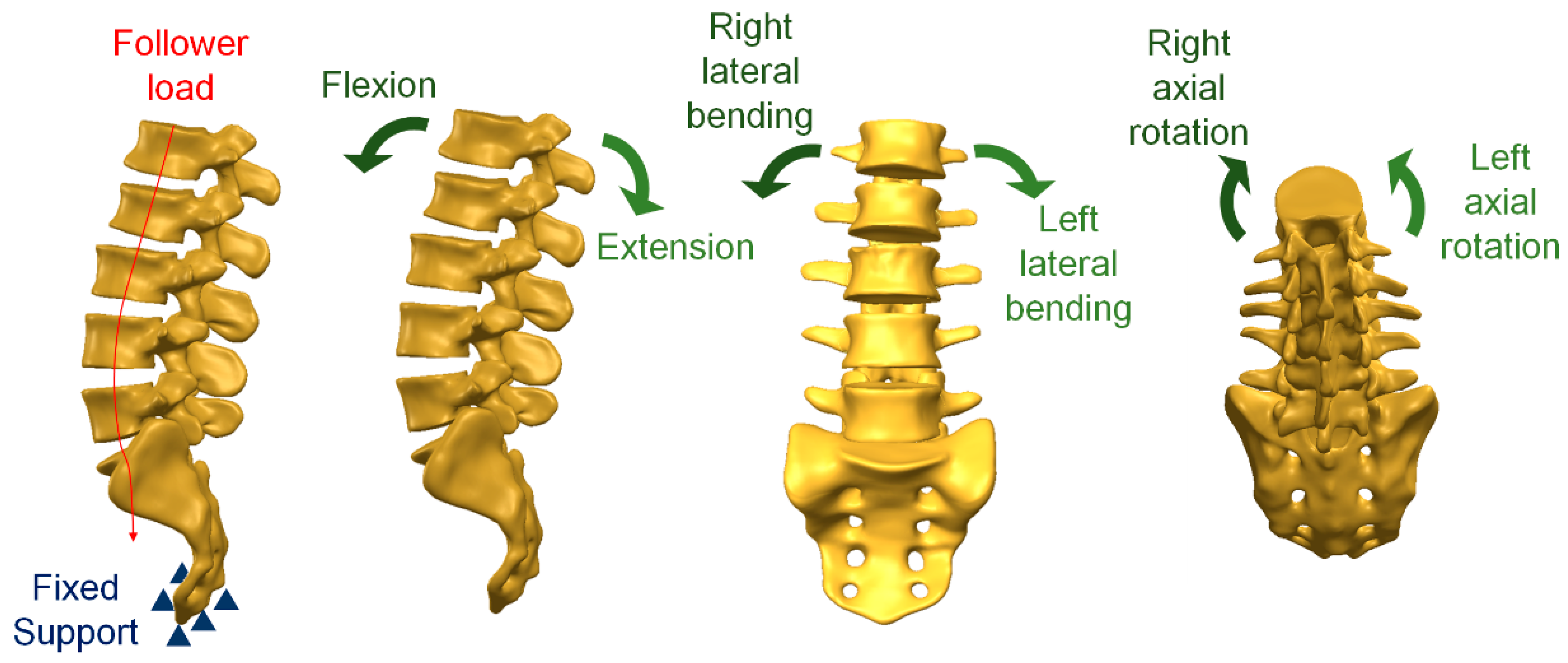
2.3. Loading and Boundary Conditions
2.4. Material Properties of the Model
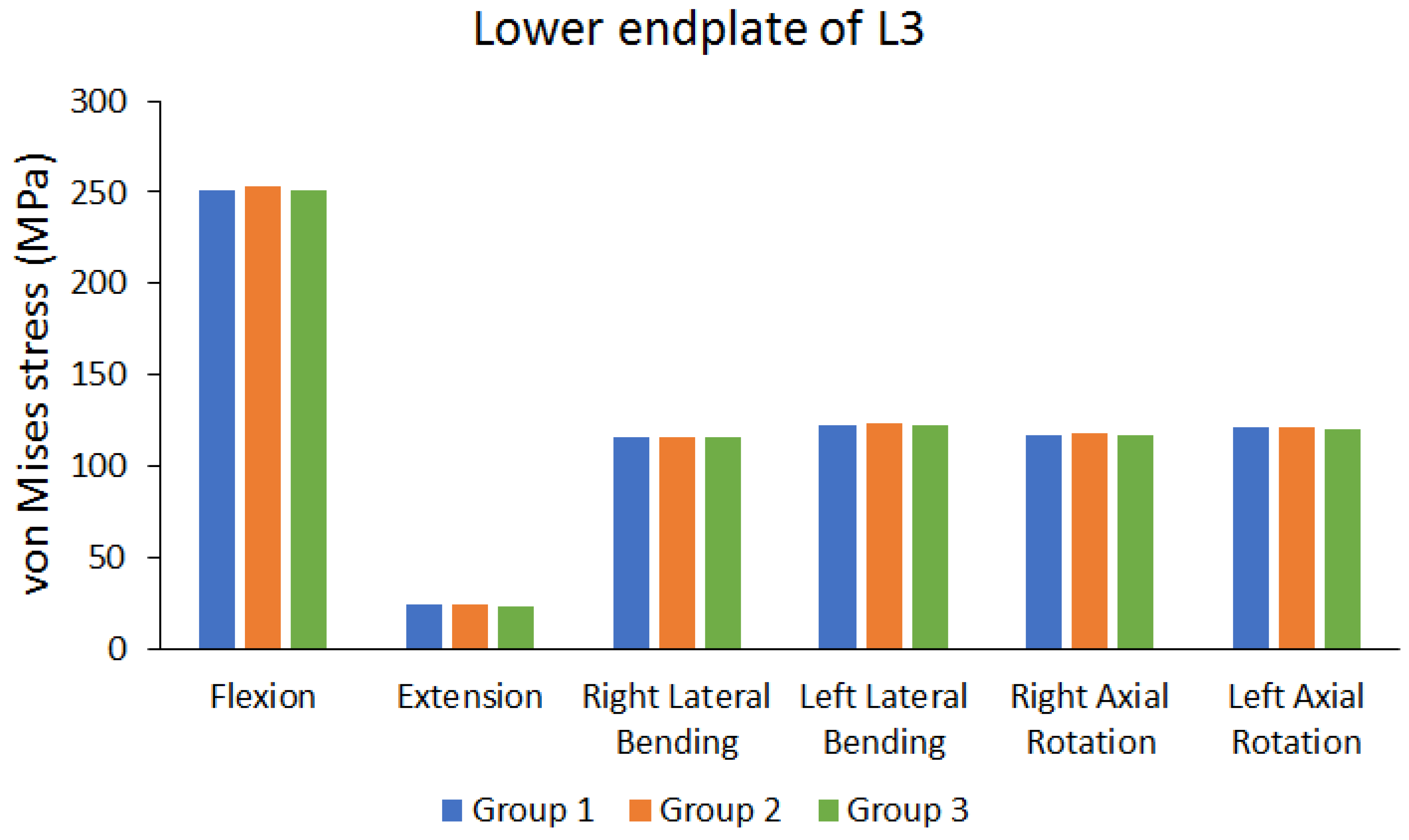
3. Results
4. Discussion
5. Conclusions
Author Contributions
Funding
Institutional Review Board Statement
Informed Consent Statement
Data Availability Statement
Acknowledgments
Conflicts of Interest
References
- Rodgers, W.B.; Gerber, E.J.; Patterson, J. Intraoperative and early postoperative complications in extreme lateral interbody fusion: An analysis of 600 cases. Spine 2011, 36, 26–32. [Google Scholar] [CrossRef] [PubMed]
- Moller, D.J.; Slimack, N.P.; Acosta, F.L.; Koski, T.R.; Fessler, R.G.; Liu, J.C. Minimally invasive lateral lumbar interbody fusion and transpsoas approach–related morbidity. Neurosurg. Focus 2011, 31, E4. [Google Scholar] [CrossRef] [PubMed]
- Patel, A.A.; Zfass-Mendez, M.; Lebwohl, N.H.; Wang, M.Y.; Green, B.A.; Levi, A.D.; Vanni, S.; Williams, S.K. Minimally invasive versus open lumbar fusion: A comparison of blood loss, surgical complications, and hospital course. Iowa Orthop. J. 2015, 35, 130. [Google Scholar]
- Brau, S.A. Mini-open approach to the spine for anterior lumbar interbody fusion: Description of the procedure, results and complications. Spine J. 2002, 2, 216–223. [Google Scholar] [CrossRef]
- Ozgur, B.M.; Agarwal, V.; Nail, E.; Pimenta, L. Two-year clinical and radiographic success of minimally invasive lateral transpsoas approach for the treatment of degenerative lumbar conditions. SAS J. 2010, 4, 41–46. [Google Scholar] [CrossRef]
- Karikari, I.O.; Nimjee, S.M.; Hardin, C.A.; Hughes, B.D.; Hodges, T.R.; Mehta, A.I.; Choi, J.; Brown, C.R.; Isaacs, R.E. Extreme lateral interbody fusion approach for isolated thoracic and thoracolumbar spine diseases: Initial clinical experience and early outcomes. Clin. Spine Surg. 2011, 24, 368–375. [Google Scholar] [CrossRef] [PubMed]
- Johnston, C., 2nd; Ashman, R.; Baird, A.; Allard, R. Effect of spinal construct stiffness on early fusion mass incorporation. Experimental study. Spine 1990, 15, 908–912. [Google Scholar] [CrossRef] [PubMed]
- Johnston, C.E.; Welch, R.D.; Baker, K.J.; Ashman, R.B. Effect of spinal construct stiffness on short segment fusion mass incorporation. Spine 1995, 20, 2400–2407. [Google Scholar] [CrossRef]
- Farber, S.H.; Pacult, M.A.; Godzik, J.; Walker, C.T.; Turner, J.D.; Porter, R.W.; Uribe, J.S. Robotics in spine surgery: A technical overview and review of key concepts. Front. Surg. 2021, 8, 578674. [Google Scholar] [CrossRef]
- Mills, E.S.; Treloar, J.; Idowu, O.; Shelby, T.; Alluri, R.K.; Hah, R.J. Single position lumbar fusion: A systematic review and meta-analysis. Spine J. 2022, 22, 429–443. [Google Scholar] [CrossRef]
- DenHaese, R.; Gandhi, A.; Ferry, C.; Farmer, S.; Porter, R. An in vitro biomechanical evaluation of a lateral lumbar interbody fusion device with integrated lateral modular plate fixation. Glob. Spine J. 2021, 11, 351–358. [Google Scholar] [CrossRef] [PubMed]
- Chen, D.-j.; Yao, C.; Song, Q.; Tang, B.; Liu, X.; Zhang, B.; Dai, M.; Nie, T.; Wan, Z. Unilateral versus bilateral pedicle screw fixation combined with transforaminal lumbar interbody fusion for the treatment of low lumbar degenerative disc diseases: Analysis of clinical and radiographic results. World Neurosurg. 2018, 115, e516–e522. [Google Scholar] [CrossRef]
- Lu, P.; Pan, T.; Dai, T.; Chen, G.; Shi, K.-Q. Is unilateral pedicle screw fixation superior than bilateral pedicle screw fixation for lumbar degenerative diseases: A meta-analysis. J. Orthop. Surg. Res. 2018, 13, 296. [Google Scholar] [CrossRef] [PubMed]
- Kim, T.-H.; Lee, B.H.; Moon, S.-H.; Lee, S.-H.; Lee, H.-M. Comparison of adjacent segment degeneration after successful posterolateral fusion with unilateral or bilateral pedicle screw instrumentation: A minimum 10-year follow-up. Spine J. 2013, 13, 1208–1216. [Google Scholar] [CrossRef]
- Du, C.-F.; Cai, X.-Y.; Gui, W.; Sun, M.-S.; Liu, Z.-X.; Liu, C.-J.; Zhang, C.-Q.; Huang, Y.-P. Does oblique lumbar interbody fusion promote adjacent degeneration in degenerative disc disease: A finite element analysis. Comput. Biol. Med. 2021, 128, 104122. [Google Scholar] [CrossRef] [PubMed]
- Zhang, S.; Liu, Z.; Lu, C.; Zhao, L.; Feng, C.; Wang, Y.; Zhang, Y. Oblique lateral interbody fusion combined with different internal fixations for the treatment of degenerative lumbar spine disease: A finite element analysis. BMC Musculoskelet. Disord. 2022, 23, 206. [Google Scholar] [CrossRef]
- Guo, H.Z.; Tang, Y.C.; Guo, D.Q.; Luo, P.J.; Li, Y.X.; Mo, G.Y.; Ma, Y.H.; Peng, J.C.; Liang, D.; Zhang, S.C. Stability evaluation of oblique lumbar interbody fusion constructs with various fixation options: A finite element analysis based on three-dimensional scanning models. World Neurosurg. 2020, 138, e530–e538. [Google Scholar] [CrossRef] [PubMed]
- Cai, X.-Y.; Bian, H.-M.; Chen, C.; Ma, X.-L.; Yang, Q. Biomechanical study of oblique lumbar interbody fusion (OLIF) augmented with different types of instrumentation: A finite element analysis. J. Orthop. Surg. Res. 2022, 17, 269. [Google Scholar] [CrossRef]
- Zeng, Z.L.; Zhu, R.; Wu, Y.C.; Zuo, W.; Yu, Y.; Wang, J.J.; Cheng, L.M. Effect of graded facetectomy on lumbar biomechanics. J. Healthc. Eng. 2017, 2017, 7981513. [Google Scholar] [CrossRef]
- Charles, Y.P.; Lima, L.V.P.C.; Persohn, S.; Rouch, P.; Steib, J.-P.; Skalli, W. Influence of an auxiliary facet system on intervertebral discs and adjacent facet joints. Spine J. 2013, 13, 1293–1300. [Google Scholar] [CrossRef]
- Denoziere, G.; Ku, D.N. Biomechanical comparison between fusion of two vertebrae and implantation of an artificial intervertebral disc. J. Biomech. 2006, 39, 766–775. [Google Scholar] [CrossRef]
- Kim, H.-J.; Kang, K.-T.; Son, J.; Lee, C.-K.; Chang, B.-S.; Yeom, J.S. The influence of facet joint orientation and tropism on the stress at the adjacent segment after lumbar fusion surgery: A biomechanical analysis. Spine J. 2015, 15, 1841–1847. [Google Scholar] [CrossRef] [PubMed]
- Wu, Y.; Wang, Y.; Wu, J.; Guan, J.; Mao, N.; Lu, C.; Lv, R.; Ding, M.; Shi, Z.; Cai, B. Study of double-level degeneration of lower lumbar spines by finite element model. World Neurosurg. 2016, 86, 294–299. [Google Scholar] [CrossRef] [PubMed]
- Kim, Y. Finite element analysis of anterior lumbar interbody fusion: Threaded cylindrical cage and pedicle screw fixation. Spine 2007, 32, 2558–2568. [Google Scholar] [CrossRef]
- Ambati, D.V.; Wright, E.K., Jr.; Lehman, R.A., Jr.; Kang, D.G.; Wagner, S.C.; Dmitriev, A.E. Bilateral pedicle screw fixation provides superior biomechanical stability in transforaminal lumbar interbody fusion: A finite element study. Spine J. 2015, 15, 1812–1822. [Google Scholar] [CrossRef]
- Zhong, Z.C.; Wei, S.H.; Wang, J.P.; Feng, C.K.; Chen, C.S.; Yu, C.H. Finite element analysis of the lumbar spine with a new cage using a topology optimization method. Med. Eng. Phys. 2006, 28, 90–98. [Google Scholar] [CrossRef] [PubMed]
- Enderle, J.; Bronzino, J. Introduction to Biomedical Engineering, 3rd ed.; Academic Press: Cambridge, MA, USA, 2012. [Google Scholar]
- Tsai, M.-T.; Lee, C.-H.; Chen, K.-H.; Yen, Y.-C.; Wang, C.-H.; Wang, S.-P.; Su, K.-C. Trochanteric Nails for the Reduction of Intertrochanteric Fractures: A Biomechanical Analysis Based on Finite Element Analysis and DIC System. J. Med. Biol. Eng. 2022, 42, 459–468. [Google Scholar] [CrossRef]
- Liao, Y.; Yan, Y.; Kang, Y.; Wang, W.; Song, X.; Peng, W.; Fu, H.; Chen, H.; Wang, C. Biomechanical Analysis of the External Fixation in a Lumbar Fracture Model: A Finite Element Study. J. Med. Biol. Eng. 2022, 42, 469–478. [Google Scholar] [CrossRef]


| Materials | Young’s Modulus (MPa) | Poisson’s Ratio |
|---|---|---|
| Cortical bone | 12,000 | 0.3 |
| Cancellous bone | 100 | 0.3 |
| Endplate: central | 2000 | 0.3 |
| Endplate: intermediate | 6000 | 0.3 |
| Endplate: outer | 12,000 | 0.3 |
| Posterior elements | 3500 | 0.25 |
| Nucleus pulposus | 1 | 0.499 |
| Annulus fibrosus 1–2 (outermost layers) | 550 | 0.3 |
| Annulus fibrosus 3–4 | 485 | 0.3 |
| Annulus fibrosus 5–6 | 420 | 0.3 |
| Annulus fibrosus 7 (innermost layer) | 360 | 0.3 |
| Annulus ground substance | 4.2 | 0.45 |
| Anterior longitudinal ligament | 20 | 0.3 |
| Posterior longitudinal ligament | 20 | 0.3 |
| Ligamentum flavum | 19.5 | 0.3 |
| Interspinous ligament | 11.6 | 0.3 |
| Supraspinous ligament | 15 | 0.3 |
| Intertransverse ligament | 58.7 | 0.3 |
| Facet capsulary ligament | 32.9 | 0.3 |
| Titanium alloy | 110,000 | 0.3 |
| Mesh | Group 1 | Group 2 | Group 3 |
|---|---|---|---|
| Number of nodes | 1,625,598 | 1,611,840 | 1,611,185 |
| Number of elements | 395,903 | 389,745 | 389,648 |
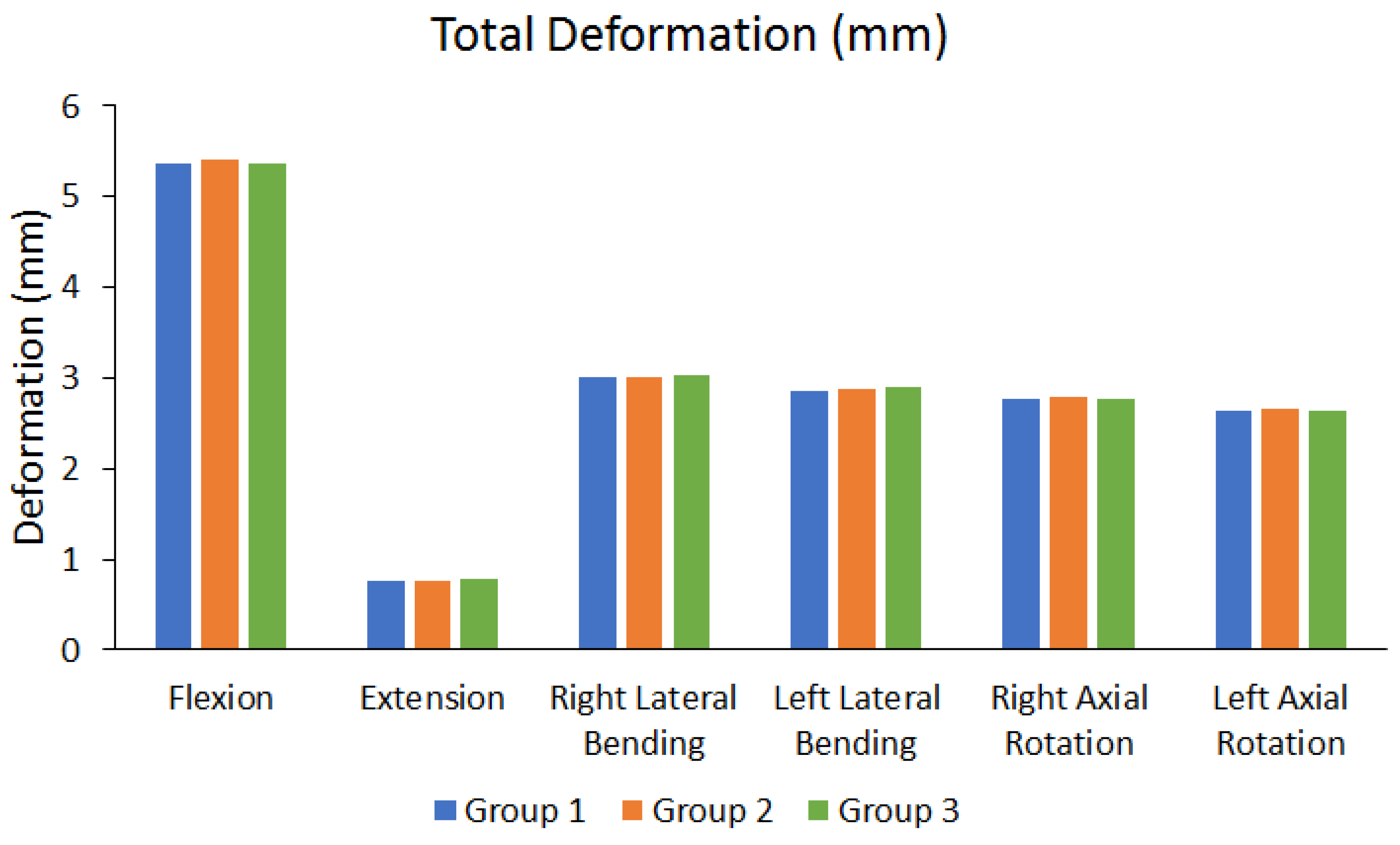
| Flexion | Extension | Right Lateral Bending | Left Lateral Bending | Right Axial Rotation | Left Axial Rotation | ||
|---|---|---|---|---|---|---|---|
| Total Deformation | Group 1 (mm) | 5.3623 | 0.76322 | 3.0041 | 2.8574 | 2.768 | 2.6459 |
| Group 2 (mm) | 5.4011 | 0.76303 | 3.0198 | 2.8786 | 2.785 | 2.6634 | |
| Group 3 (mm) | 5.3604 | 0.77297 | 3.0291 | 2.8957 | 2.7676 | 2.6454 | |
| The maximum difference between each group (%) | 0.7536% | 1.2859% | 0.8253% | 1.3227% | 0.6248% | 0.6758% |
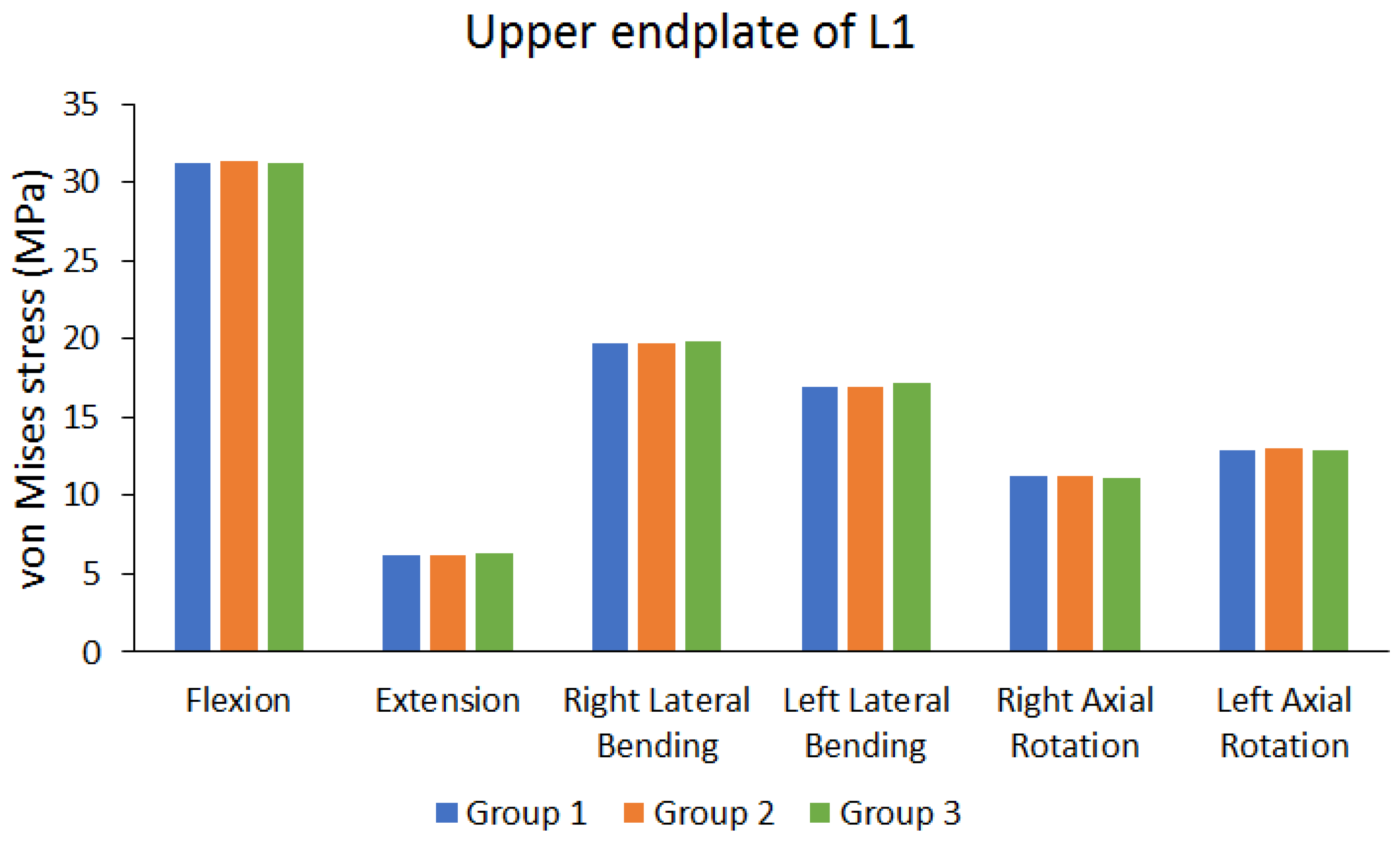
| Flexion | Extension | Right Lateral Bending | Left Lateral Bending | Right Axial Rotation | Left Axial Rotation | ||
|---|---|---|---|---|---|---|---|
| Peak von Mises stress of upper endplate of L1 | Group 1 (MPa) | 31.193 | 6.2037 | 19.694 | 16.878 | 11.184 | 12.9 |
| Group 2 (MPa) | 31.394 | 6.1918 | 19.764 | 16.978 | 11.258 | 12.978 | |
| Group 3 (MPa) | 31.19 | 6.3583 | 19.843 | 17.135 | 11.137 | 12.889 | |
| The maximum difference between each group (%) | 0.6498% | 2.6186% | 0.7509% | 1.4999% | 1.0748% | 0.6858% | |
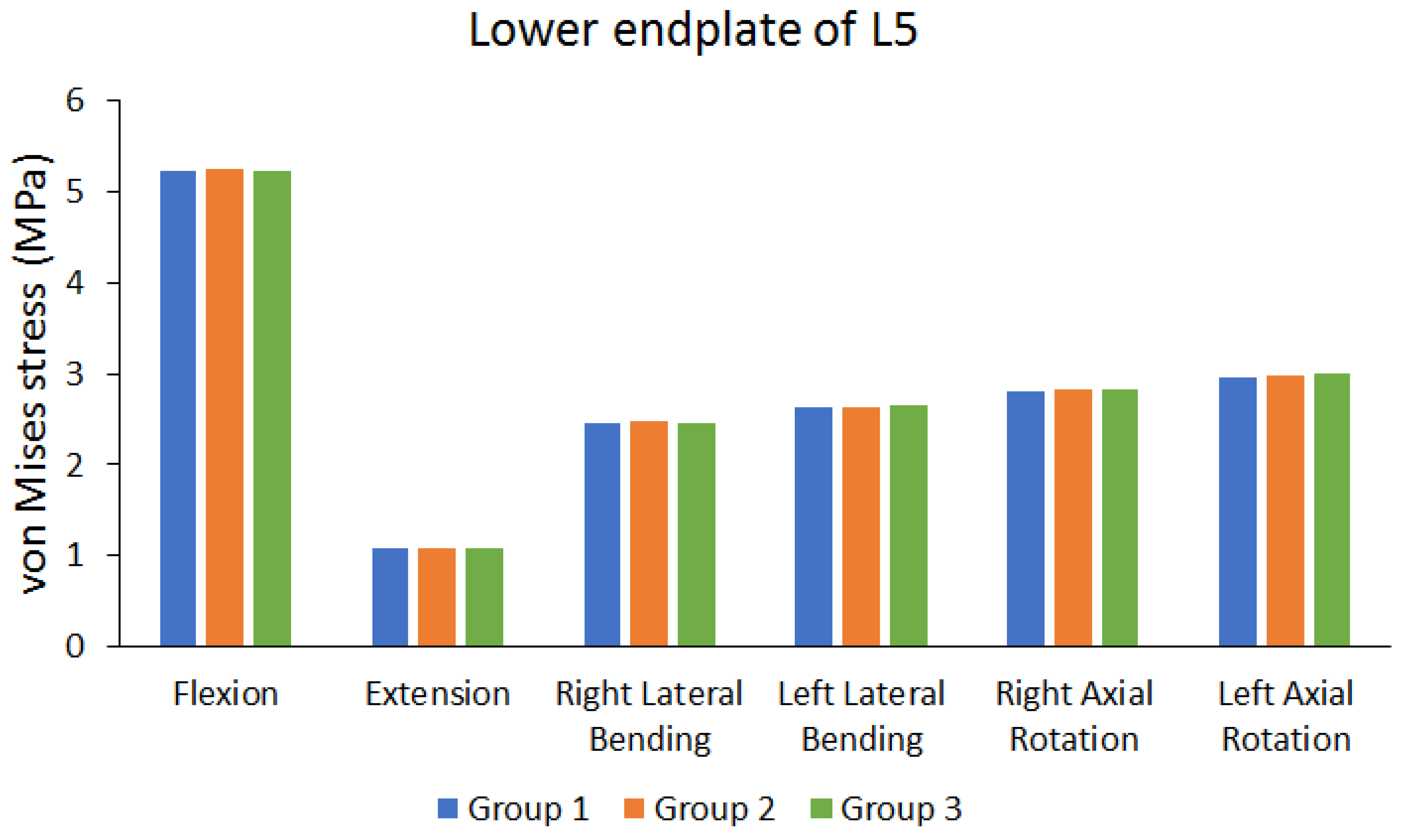
| Peak von Mises stress of lower endplate of L5 | Group 1 (MPa) | 5.2205 | 1.0727 | 2.4574 | 2.6281 | 2.8074 | 2.9604 |
| Group 2 (MPa) | 5.257 | 1.0757 | 2.4719 | 2.6401 | 2.8263 | 2.9819 | |
| Group 3 (MPa) | 5.2374 | 1.0798 | 2.4524 | 2.6613 | 2.835 | 2.9952 | |
| The maximum difference between each group (%) | 0.6943% | 0.6575% | 0.7889% | 1.2475% | 0.9735% | 1.1619% | |
| Peak von Mises stress of lower endplate of L3 | Group 1 (MPa) | 251.31 | 23.539 | 115.35 | 122.35 | 116.83 | 120.65 |
| Group 2 (MPa) | 253.42 | 23.513 | 116.02 | 123.44 | 117.71 | 121.68 | |
| Group 3 (MPa) | 250.76 | 23.262 | 115.47 | 122.3 | 116.47 | 120.21 | |
| The maximum difference between each group (%) | 1.0496% | 1.1768% | 0.5775% | 0.9235% | 1.0534% | 1.2081% | |
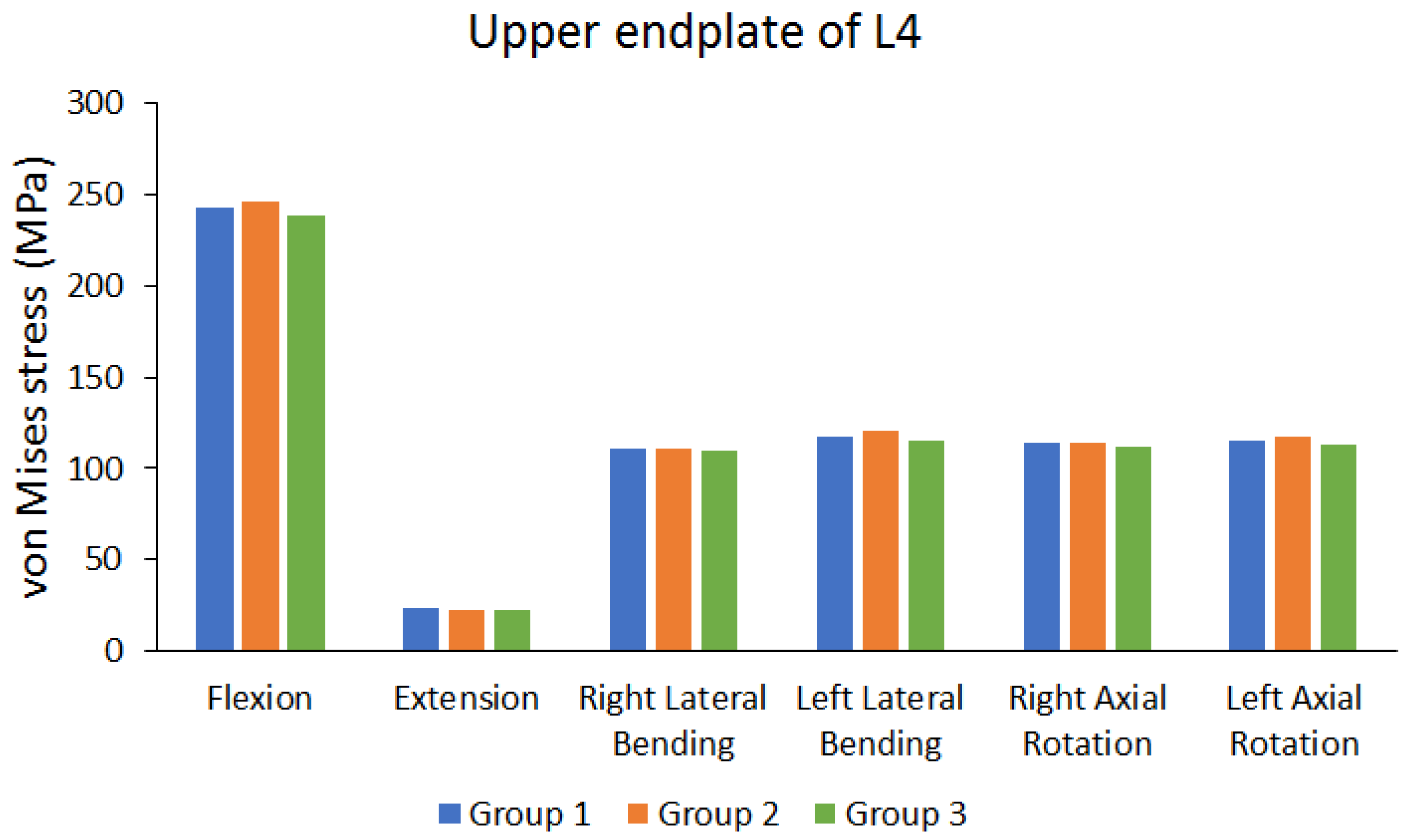
| Peak von Mises stress of upper endplate of L4 | Group 1 (MPa) | 242.97 | 23.481 | 111.22 | 117.77 | 114.51 | 115.01 |
| Group 2 (MPa) | 245.92 | 22.697 | 110.92 | 120.81 | 114.1 | 117.76 | |
| Group 3 (MPa) | 238.01 | 22.884 | 109.48 | 115.4 | 112.2 | 112.54 | |
| The maximum difference between each group (%) | 3.2165% | 3.3389% | 1.5645% | 4.4781% | 2.0173% | 4.4327% | |
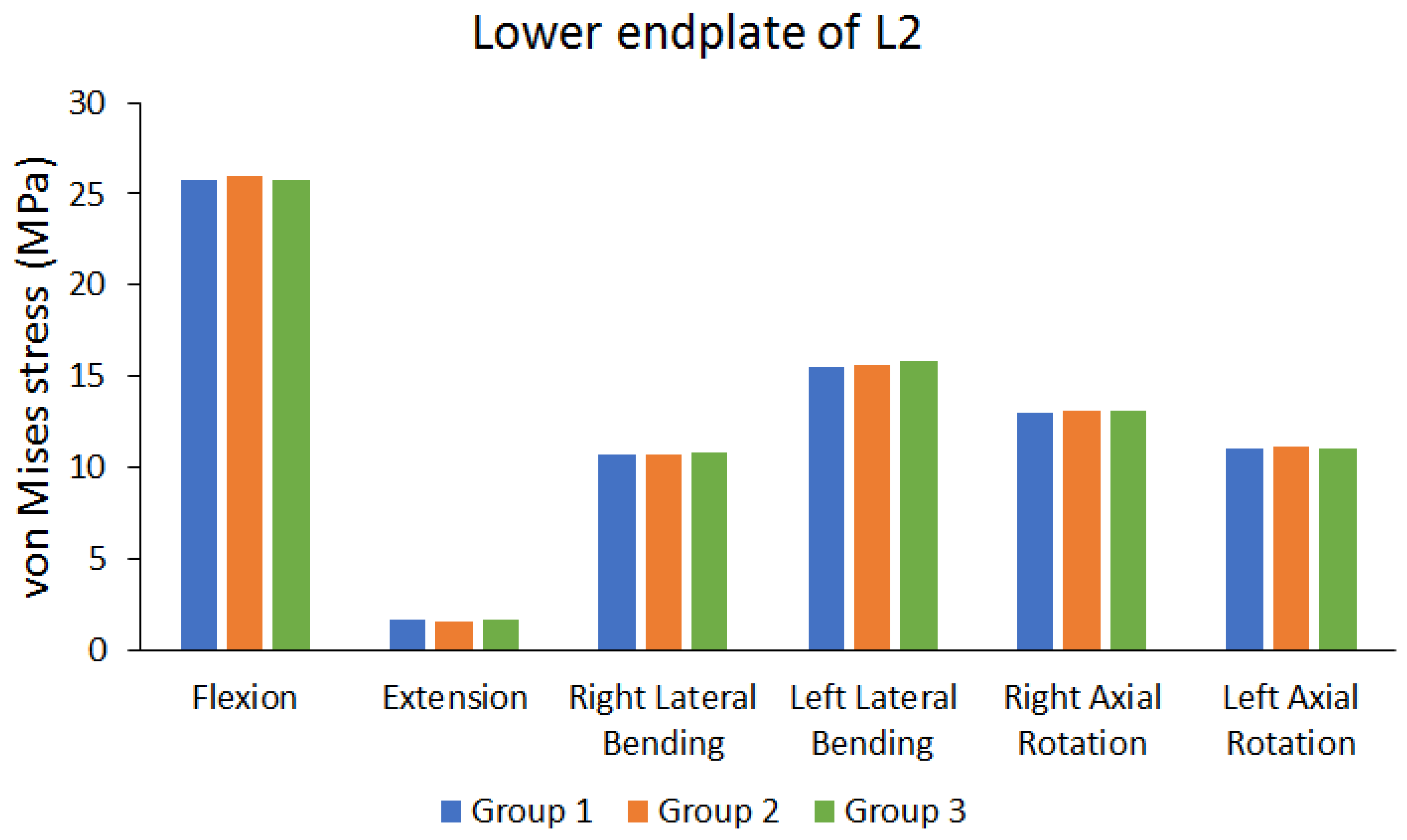
| Peak von Mises stress of lower endplate of L2 | Group 1 (MPa) | 25.755 | 1.6286 | 10.657 | 15.469 | 13.041 | 11.019 |
| Group 2 (MPa) | 25.972 | 1.5774 | 10.718 | 15.634 | 13.119 | 11.097 | |
| Group 3 (MPa) | 25.801 | 1.6606 | 10.781 | 15.818 | 13.099 | 11.01 | |
| The maximum difference between each group (%) | 0.8355% | 5.0102% | 1.1502% | 2.2063% | 0.5946% | 0.7840% | |
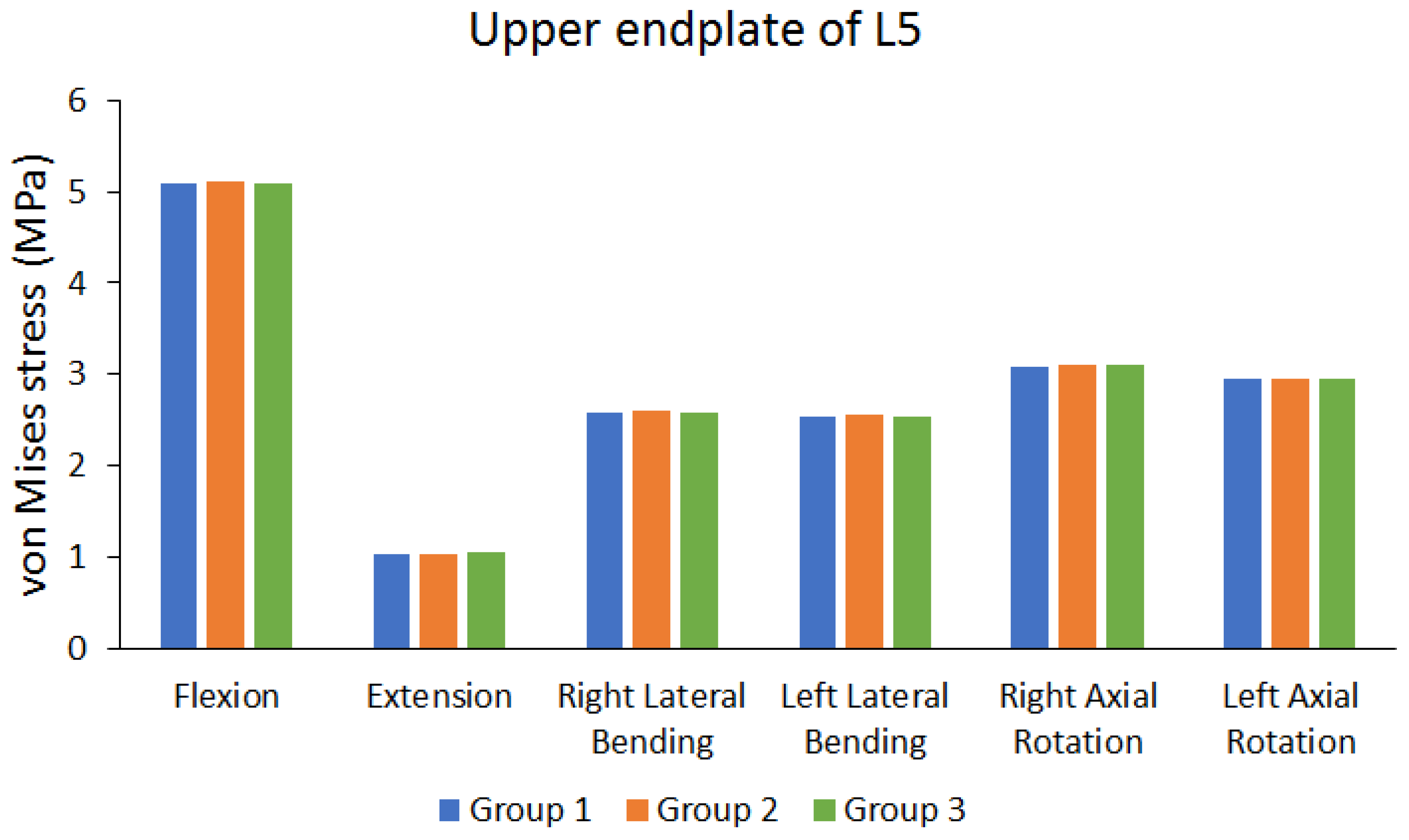
| Peak von Mises stress of upper endplate of L5 | Group 1 (MPa) | 5.0849 | 1.0358 | 2.5806 | 2.5379 | 3.0743 | 2.9458 |
| Group 2 (MPa) | 5.1124 | 1.0392 | 2.5949 | 2.5495 | 3.0928 | 2.9612 | |
| Group 3 (MPa) | 5.0833 | 1.0416 | 2.5756 | 2.5466 | 3.0932 | 2.9483 | |
| The maximum difference between each group (%) | 0.5692% | 0.5568% | 0.7438% | 0.4550% | 0.6110% | 0.5201% |
| Flexion | Extension | Right Lateral Bending | Left Lateral Bending | Right Axial Rotation | Left Axial Rotation | ||
|---|---|---|---|---|---|---|---|
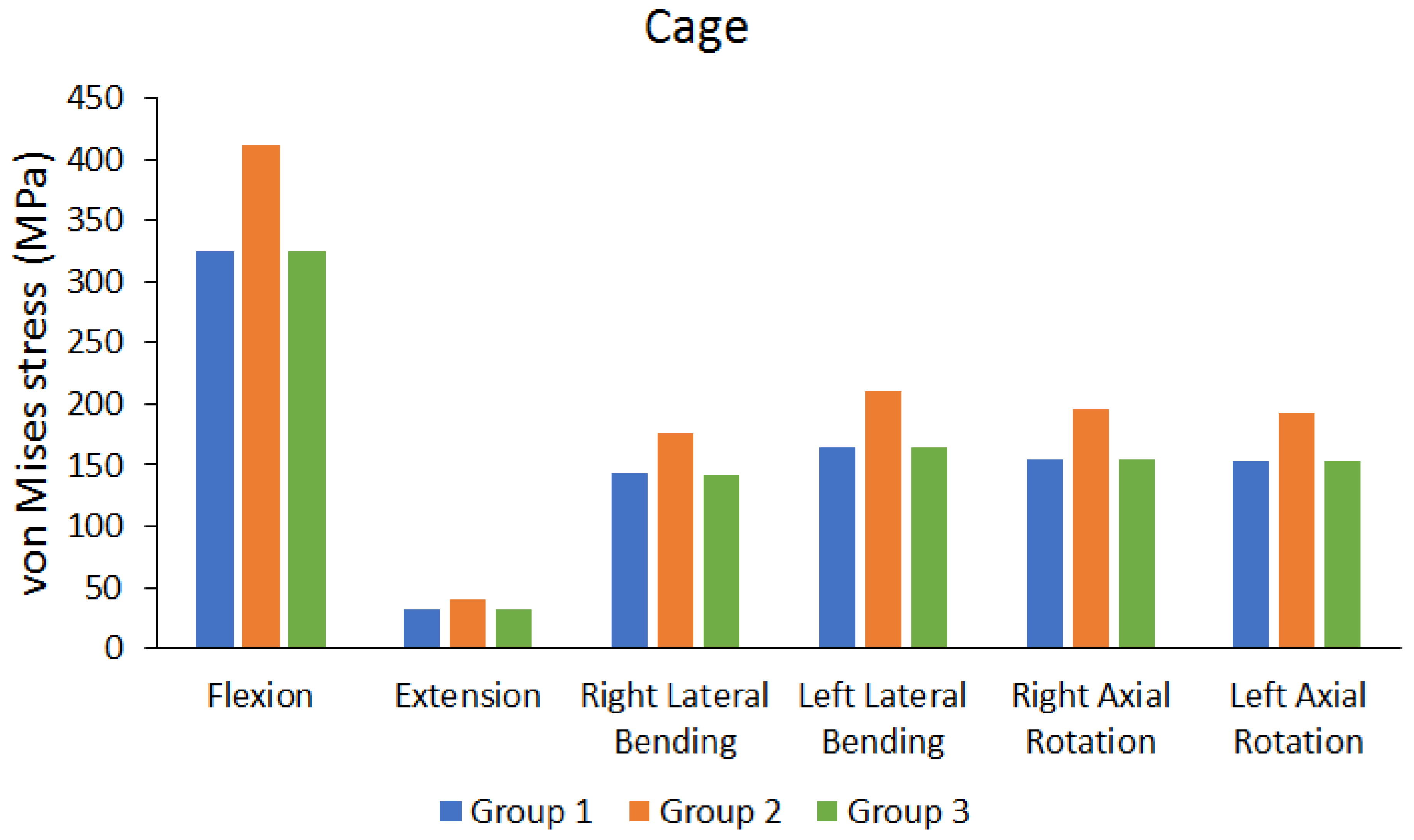
| Peak von Mises stress of cage | Group 1 (MPa) | 325.74 | 31.45 | 142.67 | 164.1 | 154.33 | 152.95 |
| Group 2 (MPa) | 411.08 | 39.45 | 176.14 | 210.17 | 194.98 | 192.62 | |
| Group 3 (MPa) | 325.34 | 31.419 | 142.37 | 164.64 | 154.25 | 152.66 | |
| Differences between BPSF and LPSF Group (%) | 0.1228% | 0.0986% | 0.2103% | 0.3280% | 0.0518% | 0.1896% | |
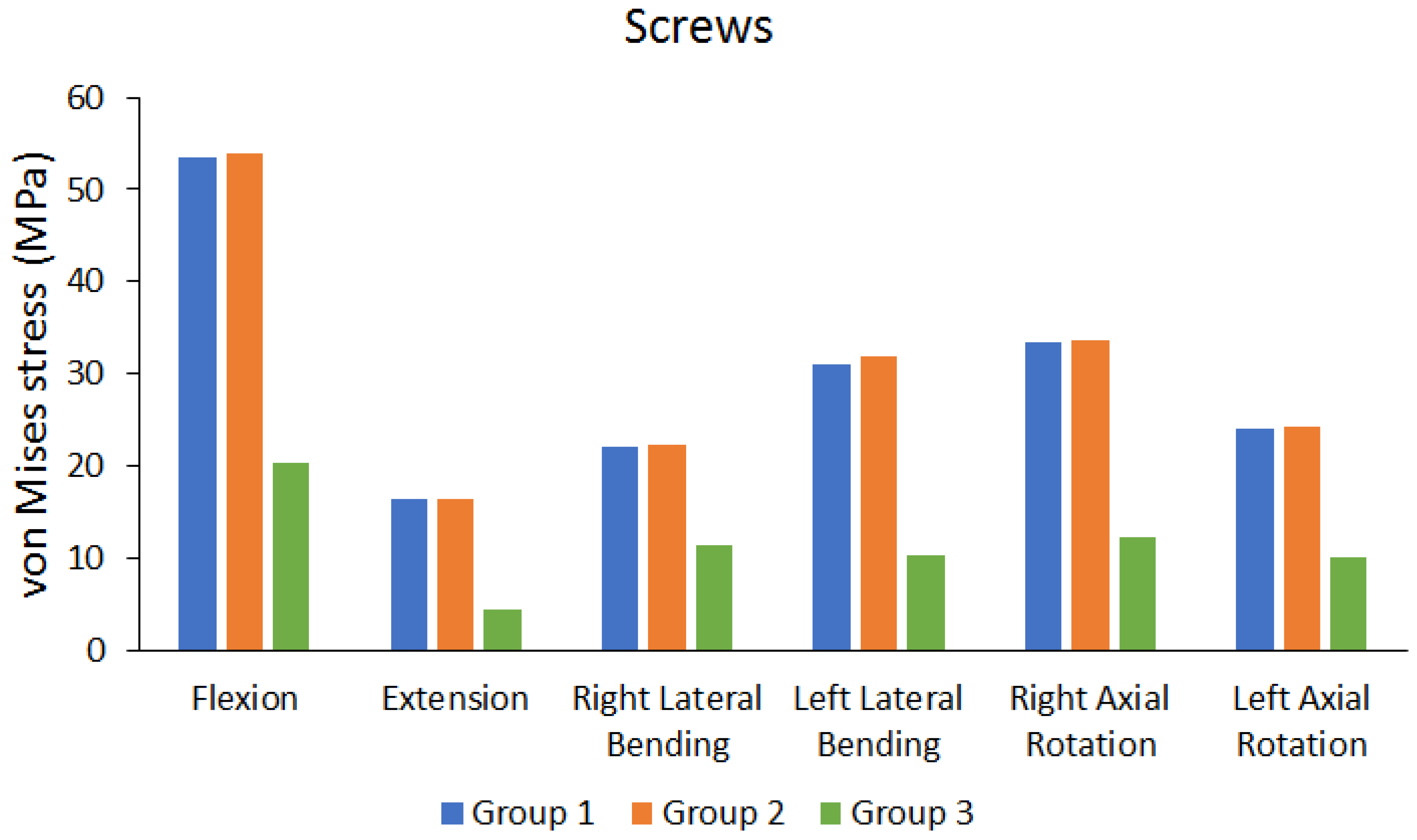
| Peak von Mises stress of screws | Group 1 (MPa) | 53.47 | 16.433 | 21.978 | 30.983 | 33.401 | 24.073 |
| Group 2 (MPa) | 53.857 | 16.371 | 22.307 | 31.791 | 33.692 | 24.272 | |
| Group 3 (MPa) | 20.376 | 4.4699 | 11.28 | 10.22 | 12.327 | 10.127 | |
| Differences between UPSF and BPSF Group (%) | 0.7186% | 0.3773% | 1.4749% | 2.5416% | 0.8637% | 0.8199% |
Disclaimer/Publisher’s Note: The statements, opinions and data contained in all publications are solely those of the individual author(s) and contributor(s) and not of MDPI and/or the editor(s). MDPI and/or the editor(s) disclaim responsibility for any injury to people or property resulting from any ideas, methods, instructions or products referred to in the content. |
© 2023 by the authors. Licensee MDPI, Basel, Switzerland. This article is an open access article distributed under the terms and conditions of the Creative Commons Attribution (CC BY) license (https://creativecommons.org/licenses/by/4.0/).
Share and Cite
Pan, C.-C.; Lee, C.-H.; Chen, K.-H.; Yen, Y.-C.; Su, K.-C. Comparative Biomechanical Analysis of Unilateral, Bilateral, and Lateral Pedicle Screw Implantation in Oblique Lumbar Interbody Fusion: A Finite Element Study. Bioengineering 2023, 10, 1238. https://doi.org/10.3390/bioengineering10111238
Pan C-C, Lee C-H, Chen K-H, Yen Y-C, Su K-C. Comparative Biomechanical Analysis of Unilateral, Bilateral, and Lateral Pedicle Screw Implantation in Oblique Lumbar Interbody Fusion: A Finite Element Study. Bioengineering. 2023; 10(11):1238. https://doi.org/10.3390/bioengineering10111238
Chicago/Turabian StylePan, Chien-Chou, Cheng-Hung Lee, Kun-Hui Chen, Yu-Chun Yen, and Kuo-Chih Su. 2023. "Comparative Biomechanical Analysis of Unilateral, Bilateral, and Lateral Pedicle Screw Implantation in Oblique Lumbar Interbody Fusion: A Finite Element Study" Bioengineering 10, no. 11: 1238. https://doi.org/10.3390/bioengineering10111238
APA StylePan, C.-C., Lee, C.-H., Chen, K.-H., Yen, Y.-C., & Su, K.-C. (2023). Comparative Biomechanical Analysis of Unilateral, Bilateral, and Lateral Pedicle Screw Implantation in Oblique Lumbar Interbody Fusion: A Finite Element Study. Bioengineering, 10(11), 1238. https://doi.org/10.3390/bioengineering10111238