Technical Note

Ground-Penetrating Radar Detection of Hydrologic Connectivity in a Covered Karstic Setting

by
Joseph P. Honings
1,*,
Carol M. Wicks
1,* and
Steven T. Brantley
2
1
Department of Geology & Geophysics, Louisiana State University, Baton Rouge, LA 70803, USA
2
The Jones Center at Ichauway, 3988 Jones Center Drive, Newton, GA 39870, USA
*
Authors to whom correspondence should be addressed.
Hydrology 2022, 9(10), 168; https://doi.org/10.3390/hydrology9100168
Submission received: 24 August 2022 / Revised: 15 September 2022 / Accepted: 23 September 2022 / Published: 26 September 2022

Abstract

:
Increasing demand for water for agricultural use within the Dougherty Plain of the southeastern United States has depleted surface water bodies. In karstic landscapes, such as the Dougherty Plain in southwest Georgia where the linkages between surface and ground waters are close, there is a need to understand the physical characteristics of the subsurface that allow these close linkages. Having a better understanding of the subsurface characteristics will aid numerical modeling efforts that underpin policy decisions and economic analyses. Two common features on this karstic landscape are draws and geographically isolated wetlands. Using LiDAR, aerial imagery, and ground-penetrating radar, this study investigates the subsurface characteristics of a draw and a series of geographically isolated wetlands. GPR reflections indicative of karst features are laterally continuous and connect the landscape to the nearby Ichawaynochaway Creek. The identification of the size and scale of the laterally continuous karstic features will guide the implementation of groundwater models used to determine irrigation and forest restoration programs while minimizing the impacts of water use on surface streams and the ecosystems.

1. Introduction

Increasing demand for water for agricultural uses within the Dougherty Plain of the southeastern United States is resulting in reduced stream flows and in longer durations when stream flow is below critical flow levels [1,2,3,4,5,6,7]. While agriculture is vital to the regional economy and there have been gains in implementing agricultural practices that reduce water demand [8], there still needs to be a greater understanding of the ecological consequences of such water use, particularly in hydrologically connected landscapes [9,10] such as streams and wetlands. Numerical modeling of the movement of and interactions between ground water and surface water has the potential to help elucidate the long-term effects of such water usage and conservation efforts [10]. A necessary simplification in many numerical modeling exercises is to apply water conservation practices uniformly across the landscape. However, the effects of water demand and conservation are spatially heterogenous with some locations having a higher sensitivity to changes in water levels [11]. Thus, understanding which areas on the land surface are more closely linked to changes in groundwater levels will help optimize the numerical modeling that underlies policy decisions and resulting economic analyses [12,13].
In a hydrologically connected and karstic landscape, draws and geographically isolated wetlands (GIWs) are common surface features along which groundwater–surface water interactions may occur [14]. Geographically-isolated wetlands (GIWs) are completely surrounded by uplands at the local scale [14], though this does not mean functional isolation hydrologically, ecologically, or physiochemically [14,15]. Hydrologic movement in GIWs is difficult to observe in nature because these connections are infrequent, of short duration, or through subsurface and groundwater pathways [14,15]. The United States Department of Agriculture (USDA) Natural Resource Conservation Service (NRCS) defines a “draw” as “a small, natural watercourse cut in unconsolidated materials, generally more open with a broader floor and more gently sloping than an arroyo, ravine, or gulch, and whose present stream channel may appear inadequate to have cut the drainageway that it currently occupies” [16,17]. Wetlands in the Dougherty Plain form when clay layers accumulate within the sandy depressions that are formed by cover collapse sinkholes in the underlying limestone [18,19]. These wetlands are ponded by heavy precipitation events and overland flow into the depression, and water may breach the wetland onto a normally dry flow path in a fill-and-spill manner. However, because these wetlands are formed by underlying sinkholes, there should exist some sort of vertical piping system within the epikarst that acts as a funnel to the subsurface [20,21]. Because karst formation is favored along pre-existing joint and fracture systems [22,23,24], which do exist at the Jones Center [6,7,25,26], it is expected that wetlands, underlying sinkholes, and a connected conduit flow system would exist along this pattern, and therefore the wetlands. The surface–groundwater interaction would be seepage through the vertical piping system into the conduit system. Because sinkholes are precursors of the wetlands and evidence of subsurface dissolution, normally dry flowpaths such as draws would also serve as this groundwater–surface water connection even in the absence of wetlands.
In building numerical models with spatially distributed recharge, there is a need to know the spatial dimensions and material characteristics of these features. The Dougherty Plain [15,16] in southwestern Georgia provides an ideal model system to characterize these features in an area dominated by groundwater–surface water interactions [27] and intensive agriculture. The region contains thousands of GIWs [2] and numerous draws. Therefore, the objective of this study is to use ground-penetrating radar to determine the spatial dimensions and material characteristics of a series of GIWs and of one draw in a relatively undisturbed landscape. These findings will constrain physical parameters of groundwater models that are used for land and water conservation efforts, inform land management and policy decisions based on the existence of a subsurface flow path, and guide the implementation of higher-efficiency center-pivot irrigation systems within a higher conductivity flow path.

2. Materials and Methods

2.1. Description of the Study Area

The ~6700-km2 Dougherty Plain [28] is a karst region within the southeastern U.S. The unconsolidated sediment consists of sand and clay, ranges between 0 to 30 m thick, and overlies the karstic Ocala Limestone [25,29] that is the groundwater reservoir in the region [1]. The unconfined nature of the aquifer allows direct interaction between surface water and groundwater [30]. Thus, surface water throughout the Dougherty Plain is connected to the groundwater allowing exchange between groundwater and surface water [11,26,31,32]. Common examples of hydrologic connectivity are the streams that are incised into and through the unconsolidated sediment resulting in swallets and in the sinkholes that expose the underlying Ocala limestone [19].
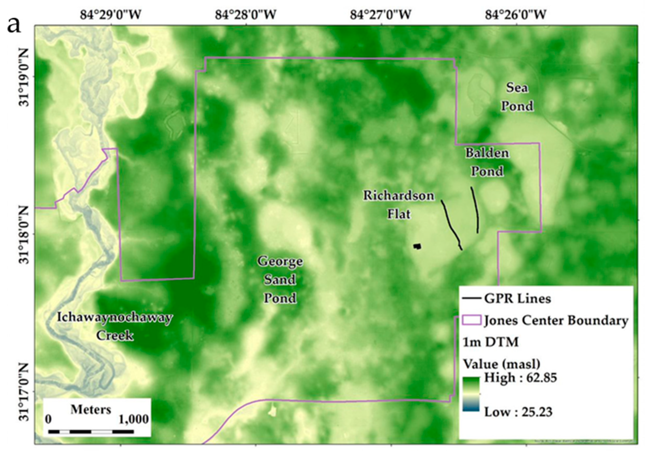
Within the Dougherty Plain lies the 117 km2 Jones Center at Ichauway, a private reserve owned by the Robert W. Woodruff Foundation and managed for conservation, research, and education (Figure 1). Within the Jones Center, fracture patterns in the limestone are apparent [7,26,31], and were used to guide selection of the draw and of the GIWs for study. Using aerial photography and digital terrain models (DTM; bare earth models derived from 1-m resolution LiDAR data [33], a several-kilometer-long linear series of GIWs was identified in the northeastern portion of the Jones Center (Figure 2a). The draw was an approximately 850-m long lineament of sinkholes between an upland portion of the Dougherty Plain and the Ichawaynochaway Creek in the central portion of the Jones Center (Figure 3a).

2.2. Data Collection

Ground-penetrating radar (GPR) is a surface geophysical technique for high-resolution visualization, and thus characterization, of soil and stratigraphic units [34]. In karstic regions, GPR has proven useful to map the depth to bedrock, the depth and geometry of sinkholes, and other dissolution features [21,35,36,37,38,39,40,41]. Water and clay content strongly attenuate GPR signal propagation in the subsurface [42]. Therefore, if the water table is at higher elevation than a karst feature, or if there is thick clay, the signal attenuation may not reveal the deeper karst feature in the GPR imagery. Kruse, Grasmueck [21] and Kruse [20] investigated the Floridan Aquifer with GPR in west-central Florida, but focused mainly on visualization of individual sinkholes. This project utilized GPR to investigate sinkhole complexes at different scales through the Dougherty Plain in southwestern Georgia.
Eleven GPR survey lines were completed with nine (9) of those lines completed in a high-density grid over a depression in the southwest corner of Richardson Flat (Figure 2a). The two remaining lines were across Richardson Flat and along a road between Richardson Flat and Balden Pond. Twenty-three (23) GPR lines were completed along the draw. All lines were completed between April 2017 and January of 2021 using a Sensors & Software PulseEkko® (Sensors & Software, Mississauga, Ontario, Canada, Model 1100) with a cart-mounted 100 MHz antenna with 1-m spacing. GPR data were examined as cross-sections using Sensors & Software Ekko Project software (Sensors & Software, Mississauga, ON, Canada, Version 5). Reflections were interpreted as geologic horizons and karst features. Due to ponded water, heavy vegetation, and thick sand deposits, the number of lines was limited.
The GPR data were visualized and processed using Ekko Project Version 5 software that includes an automatic dewow step upon import from the PulseEkko into the Ekko Project. Each survey was individually depth-corrected by determining the velocity of the unconsolidated overburden, achieved using one of two methods. The first method used the velocity calibration tool within the Ekko Project. The calibration tool was used to fit (by eye) parabolic reflector within the shallow subsurface. The velocities determined were always within the velocity range for sand and clay. If there was no obvious parabolic reflector, then the second method was to use a velocity estimated based on the field observations of the soils at the location (i.e., dry sand, moist sand, or clay (0.06 m/ns). Once the velocity had been determined, the two-way travel time was converted to depth.
The depth-converted GPR data and images were then migrated. Migration of a GPR data and image adjusts reflectors to the true subsurface positions and allows better resolution of the image. In the Ekko_Project V5 software, two (2) migration options are available, F-K (Stolt) migration and Kirchoff migration. The F-K migration uses the entire GPR line data set, whereas the Kirchoff migration uses a region around the energy source point [43]. Migration was an iterative process in which a velocity value was specified based on a reflector or the geologic medium, and the migrated images were compared against conceptual geologic models.

3. Results

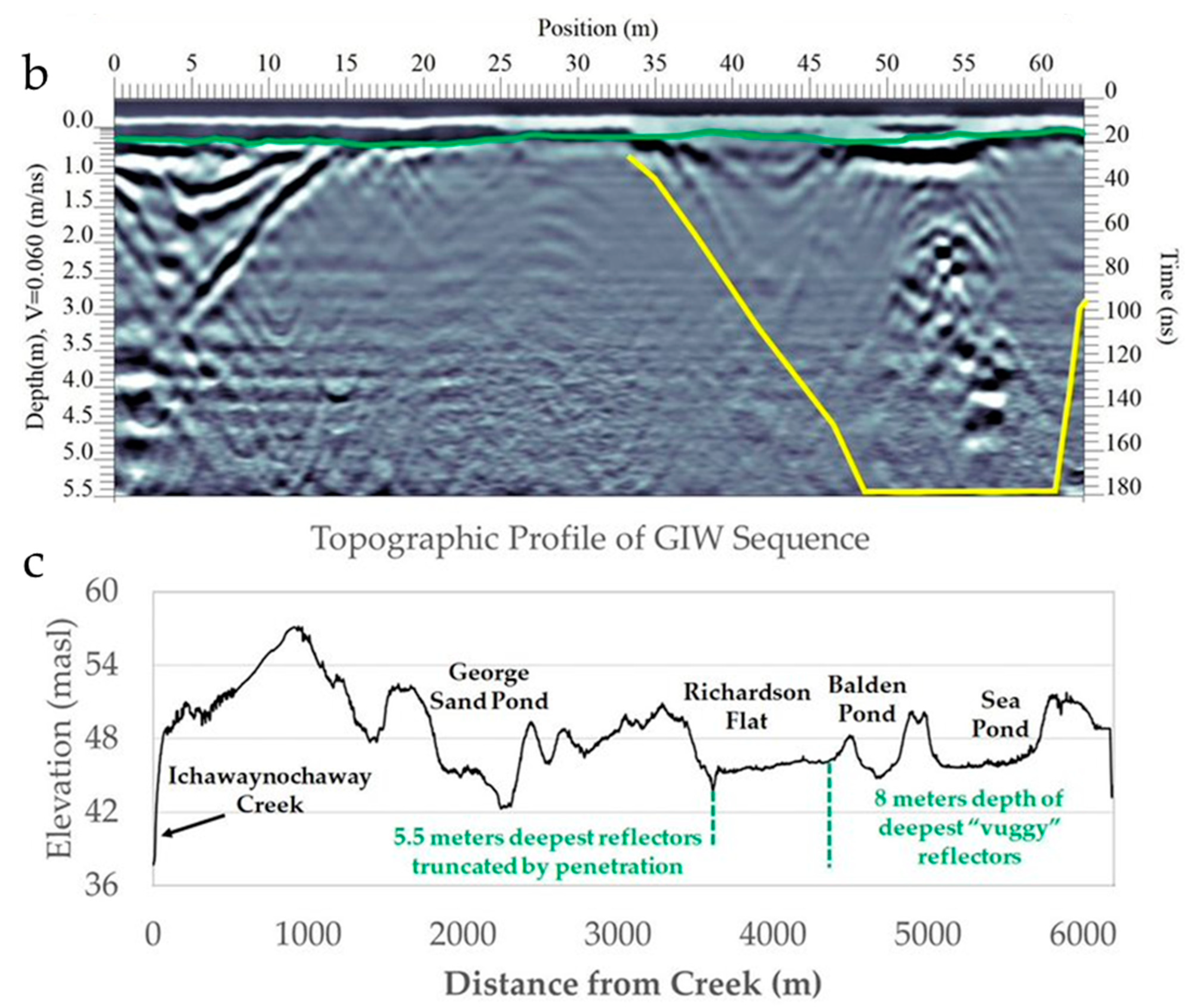
Along the main road separating Richardson Flat and Balden Pond, there are four zones of interest that are ~50, ~50, ~135, and ~105 m wide with have depths of ~3.5, ~7.0, ~5.5, and ~7.0 m, respectively (Figure 3a). Three of the zones contain strong point reflectors that are interpreted as sinkholes containing dry unconsolidated high-porosity material. The GPR velocities determined on point reflectors in the features ranged from 0.034 to 0.122 m ns−1. The third zone aligns with the lowest elevations in both Balden Pond to the east and Richardson Flat to the West. The point reflectors in this third zone are subdued, which is attributed to the presence of water causing attenuation of the GPR signal at depth, velocities ranged from 0.069 to 0.171 m ns−1. None of the velocities suggest the presence of clay (0.06 m ns−1; [42]) in the subsurface.
The high-density survey grid revealed the presence of a sinkhole that extends to a depth of ~5.5 m below the ground surface (Figure 3b). Point reflector velocities ranged from 0.068 to 0.130 m ns−1, suggesting the average velocity is increasing with depth from that of clay (0.06 m ns−1), which would mean that there is a transition into more porous sediments such as the limestone within the funnel-shaped feature.
Adding the depths of the features noted in the GPR transects to the topographic profile allows the visualization of possible hydrologic connections in the subsurface from Sea Pond to Ichawaynochaway Creek (Figure 3c). Regarding the development of numerical models, the absence of clay in the subsurface and the presence of the funnel-shaped features suggests that these GIWs should be considered funnels and not fill-and-spill features. Additionally, because these wetlands are aligned with the orientation of fractures within the limestone [7] and the absence of a subsurface barrier to water flow (no clay), this GIW sequence that is hundreds of meters wide and long is on the scale of a uvala [22,24].
Along the draw, there was consistency of reflections aligned with the sinkhole lineament in the cross-sectional data (Figure 4) that are discernable from what is interpreted as coherent Ocala Limestone. These zones, annotated with the color yellow, are interpreted as sinkhole-like funnels or concentrated vuggy zones that have yet to collapse or manifest as a depression on the surface. In some instances, cavities (Figure 4a,b) and solution-enlarged fissures (Figure 4c) were determined to be present. Typically, depth of the features extended between 6 and 10 m, with velocities between 0.08 and 0.155 m ns−1.

4. Discussion

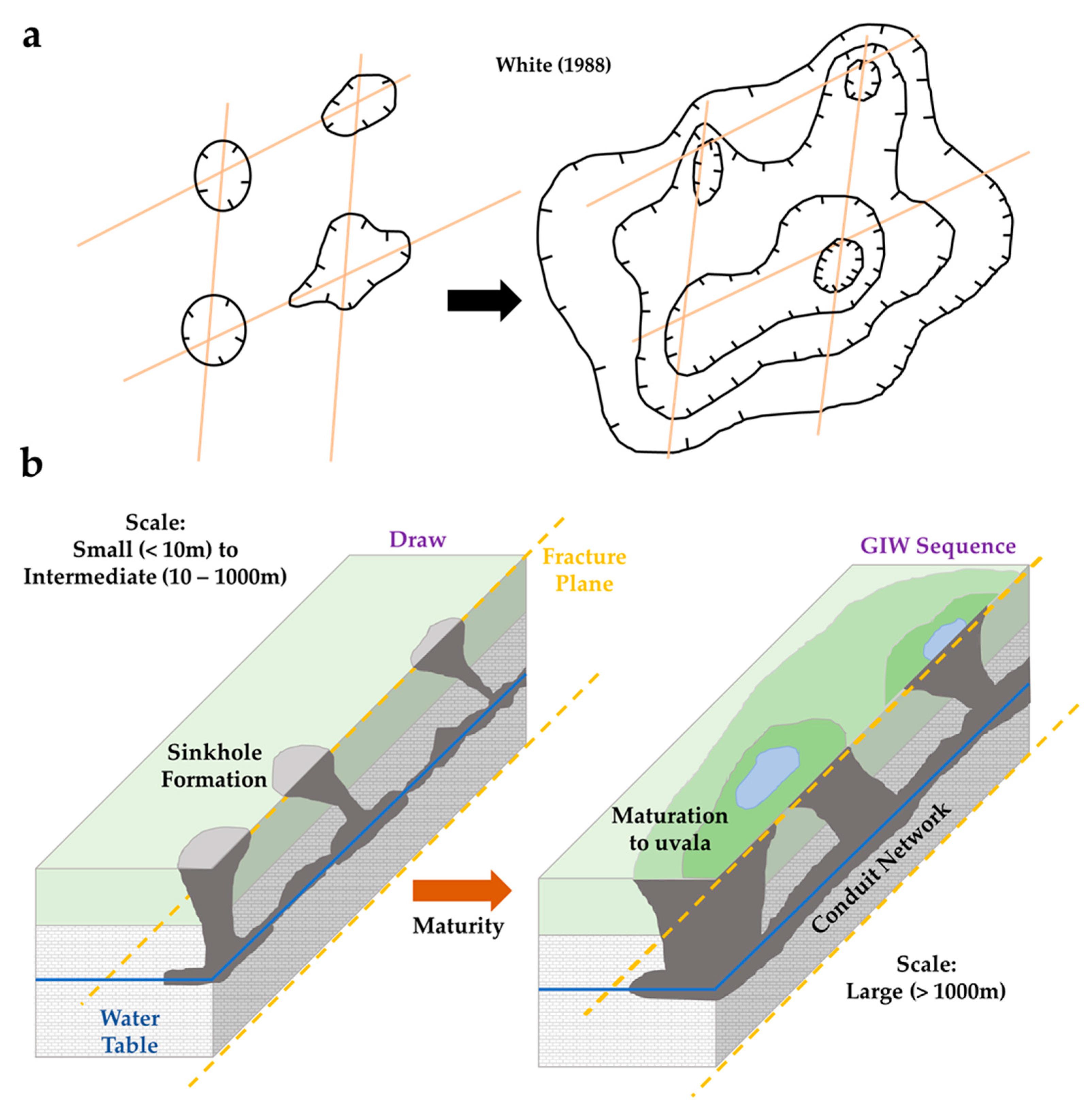
GIWs have been characterized as funnels or as spill-and-fill features [32]. Spill-and-fill behavior would have been expected if a thick, continuous clay layer had been found in the subsurface as the clay would have allowed ponding of water within the GIW by preventing downward flow of water into the subsurface. Here, the GPR results show that the clay was not encountered in significant volumes. In addition, GPR imagery shows sinkholes filled with unconsolidated material. This casts doubt on conceptualizations of these GIWs as spill-and-fill features; while, supporting the conceptualization of these GIWs as funnels. In addition, the depths of the subsurface features reveal that the funnels extend to the base level of the Ichawaynochaway Creek stream bed, possibly allowing water to flow vertically downward through the funnels and then horizontally to the stream bed, in a manner similar to that described in early work of Toth [44] and Freeze [45]. This series of GIWs is best conceptualized as a larger uvala (Figure 5) [22,24].
The orientation of the lineament within the draw matches the regional fracture pattern that was identified using aerial photography and the 1-m resolution LiDAR DTM [33]. The GPR surveys along the draw revealed evidence of a lateral subsurface connection through cavities and zones of vuggy porosity. LiDAR and other aerial imagery can be used to identify similar surface features and help to infer subsurface features and flow paths throughout the Dougherty Plain. This is useful for determining the locations of spatially heterogenous recharge and discharge features, which inform the physical parameters of groundwater models that are used for land and water conservation efforts that prioritize parcels with the presence of a subsurface flow path.
Individual sinkholes are small (< 10 m) features [22] and are common features across the Dougherty Plain. Groups of small sinkholes such as those in the draw at the Jones Center, however, are indicative of an intermediate-sized, connected feature that formed along the fracture plane [6,7,22,24,26,31] (Figure 5a). Continued karst development of the sinkholes in the draw will lead to coalescence at the surface as seen in the GIW series with better hydrologic connection in the subsurface through a conduit system (Figure 5b).
This region of Georgia is home to more than 320,000 people [2] who use groundwater as a source of domestic water and as a source for irrigating crop lands [6,28]. Because agricultural demand is expected to increase by mid-century, there is an immediate need to refine the numerical models of the coupled groundwater–surface water systems, requiring characterization of the subsurface in the UFA. Determining the thickness of sediment (without an intensive coring effort), the irregularity of the epikarstic surface, and location and size of subsurface recharge features constrains numerical groundwater flow models. This has helped us understand the linkages of recharge areas to discharge areas [11]. This study has shown that visualizing some GIWs as components of uvalas and not as isolated wetlands is a reasonable hydrologic conceptual framework. This hydrologic connectivity of a uvala does not negate the conceptual model of use of wetlands as isolated ecosystems as most of the hydrologic connectivity is below ground; whereas most ecological connections are above ground. Being able to visualize the spatial distribution of the sediment and karstic features provides insight into the size and shape of recharge features and thus, groundwater–surface water interactions. This new understanding of groundwater–surface water interaction in the Dougherty Plain can be used to inform land management and policy decisions, and deduce the optimal location of higher-efficiency irrigation systems within a subsurface flow path for improved aquifer sustainability.

Author Contributions

Conceptualization, J.P.H., C.M.W., S.T.B.; methodology, J.P.H. and C.M.W.; software, J.P.H.; formal analysis, J.P.H., C.M.W. and S.T.B.; resources, S.T.B.; data curation, C.M.W.; writing—original draft preparation, J.P.H.; writing—review and editing, C.M.W. and S.T.B.; visualization, J.P.H.; supervision, C.M.W.; project administration, C.M.W.; funding acquisition, S.T.B. All authors have read and agreed to the published version of the manuscript.

Funding

The field work portion of this research was funded by the Jones Center at Ichauway (AWD-AM221090 to CMW).

Institutional Review Board Statement

Not applicable.

Informed Consent Statement

Not applicable.

Conflicts of Interest

The authors declare no conflict of interest. The funders had no role in the design of the study; in the collection, analyses, or interpretation of data; in the writing of the manuscript, or in the decision to publish the results.

References

  1. Fanning, J.L.; Trent, V.P. Water Use in Georgia by County for 2005, and Water-Use Trends, 1980–2005; US Department of the Interior, US Geological Survey: Atlanta, GA, USA, 2009.
  2. Martin, G.I.; Hepinstall-Cyerman, J.; Kirkman, L.K. Six Decades (1948–2007) of Landscape Change in the Dougherty Plain of Southwest Georgia, USA. Southeast. Geogr. 2013, 53, 28–49. [Google Scholar] [CrossRef]
  3. Golladay, S.W.; Gagnon, P.; Kearns, M.; Battle, J.M.; Hicks, D.W. Response of freshwater mussel assemblages (Bivalvia: Unionidae) to a record drought in the Gulf Coastal Plain of southwestern Georgia. J. N. Am. Benthol. Soc. 2004, 23, 494–506. [Google Scholar] [CrossRef]
  4. Battle, J.M.; Golladay, S.W. How hydrology, habitat type, and litter quality affect leaf breakdown in wetlands on the gulf coastal plain of Georgia. Wetlands 2007, 27, 251–260. [Google Scholar] [CrossRef]
  5. Hicks, D.W.; Golladay, S.W. Impacts of Agricultural Pumping on Selected Streams in Southwestern Georgia; Georgia Environmental Protection Division: Atlanta, GA, USA; Jones Ecological Research Center: Newton, GA, USA, 2006. [Google Scholar]
  6. Rugel, K.; Jackson, C.R.; Romeis, J.J.; Golladay, S.W.; Hicks, D.W.; Dowd, J.F. Effects of irrigation withdrawals on streamflows in a karst environment: Lower Flint River Basin, Georgia, USA. Hydrol. Process. 2012, 26, 523–534. [Google Scholar] [CrossRef]
  7. Rugel, K.; Golladay, S.W.; Jackson, C.R.; McDowell, R.J.; Dowd, J.F.; Rasmussen, T.C. Using hydrogeomorphic patterns to predict groundwater discharge in a karst basin: Lower Flint River Basin, southwestern Georgia, USA. J. Hydrol. Reg. Stud. 2019, 23, 100603. [Google Scholar] [CrossRef]
  8. Vellidis, G.; Tucker, M.; Perry, C.; Kvien, C.; Bednarz, C. A real-time wireless smart sensor array for scheduling irrigation. Comput. Electron. Agric. 2008, 61, 44–50. [Google Scholar] [CrossRef]
  9. Tetzlaff, D.; Soulsby, C.; Bacon, P.; Youngson, A.; Gibbins, C.; Malcolm, I. Connectivity between landscapes and riverscapes—A unifying theme in integrating hydrology and ecology in catchment science? Hydrol. Process. Int. J. 2007, 21, 1385–1389. [Google Scholar] [CrossRef]
  10. Qi, J.; Brantley, S.; Golladay, S. Simulated irrigation reduction improves low flow in streams—A case study in the Lower Flint River Basin. J. Hydrol. Reg. Stud. 2020, 28, 100665. [Google Scholar] [CrossRef]
  11. Torak, L.J.; Painter, J.A. Geohydrology of the Lower Apalachicola-Chattahoochee-Flint River Basin, Southwestern Georgia, Northwestern Florida, and Southeastern Alabama; USGS: Reston, VA, USA, 2006.
  12. GWPCC. Lower Flint-Ochlockonee: Regional Water Plan; Black & Veatch and GWPCC: Albany, GA, USA, 2017. [Google Scholar]
  13. Jones, L.E.; Painter, J.A.; LaFontaine, J.H.; Sepúlveda, N.; Sifuentes, D.F. Groundwater-Flow Budget for the Lower Apalachicola-Chattahoochee-Flint River Basin in Southwestern Georgia and Parts of Florida and Alabama, 2008–12; US Geological Survey: Atlanta, GA, USA, 2017.
  14. Tiner, R.W. Geographically isolated wetlands of the United States. Wetlands 2003, 23, 494–516. [Google Scholar] [CrossRef]
  15. Mushet, D.M.; Calhoun, A.J.K.; Alexander, L.C.; Cohen, M.J.; DeKeyser, E.S.; Fowler, L.; Lane, C.R.; Lang, M.W.; Rains, M.C.; Walls, S.C. Geographically Isolated Wetlands: Rethinking a Misnomer. Wetlands 2015, 35, 423–431. [Google Scholar] [CrossRef] [Green Version]
  16. Daniels, R.; Raymond, B. Part 629—Glossary of Landform and Geologic Terms; USDA NRCS: Washington, DC, USA, 2017.
  17. USDA. Soil Survey Manual; US Department of Agriculture: Washington, DC, USA, 1993.
  18. Deemy, J.B.; Rasmussen, T.C. Hydrology and water quality of isolated wetlands: Stormflow changes along two episodic flowpaths. J. Hydrol. Reg. Stud. 2017, 14, 23–36. [Google Scholar] [CrossRef]
  19. Hicks, D.; Gill, H.E.; Longsworth, S. Hydrogeology, Chemical Quality, and Availability of Ground Water in the Upper Floridan Aquifer, Albany Area, Georgia; Department of the Interior, US Geological Survey: Atlanta, GA, USA, 1987.
  20. Kruse, S. Three-dimensional GPR imaging of complex structures in covered karst terrain. In Proceedings of the 15th International Conference on Ground Penetrating Radar, Brussels, Belgium, 30 June–4 July 2014. [Google Scholar]
  21. Kruse, S.; Grasmueck, M.; Weiss, M.; Viggiano, D. Sinkhole structure imaging in covered karst terrain. Geophys. Res. Lett. 2006, 33. [Google Scholar] [CrossRef]
  22. Ford, D.C.; Williams, P.W. Karst Geomorphology and Hydrology; Springer: Berlin/Heidelberg, Germany, 1989; Volume 601. [Google Scholar]
  23. Palmer, A.N. Origin and morphology of limestone caves. Geol. Soc. Am. Bull. 1991, 103, 1–21. [Google Scholar] [CrossRef]
  24. White, W.B. Geomorphology And hydrology of Karst Terrains; Oxford University Press: New York, NY, USA, 1988. [Google Scholar]
  25. Beck, B.F. A generalized genetic framework for the development of sinkholes and karst in Florida, USA. Environ. Geol. Water Sci. 1986, 8, 5–18. [Google Scholar] [CrossRef]
  26. Brook, G.; Allison, T. Fracture mapping and ground susceptibility modeling in covered karst terrain—The example of Dougherty County, Georgia. In Proceedings of the Symposium on Land Subsidence; IAHS Publication: Venice, Italy, 1986. [Google Scholar]
  27. Barrie, C.J.; Rasmussen, T.C.; Tollner, E.W.; Golladay, S.W.; Brantley, S. Steady vs dynamic stream-aquifer interactions: Lower Flint River Basin, Southwest Georgia, USA. J. Hydrol. Reg. Stud. 2022, 40, 101046. [Google Scholar]
  28. Martin, G.I.; Kirkman, L.K.; Hepinstall-Cymerman, J. Mapping geographically isolated wetlands in the Dougherty Plain, Georgia, USA. Wetlands 2012, 32, 149–160. [Google Scholar] [CrossRef]
  29. Beck, B.F.; Arden, D.D.; Institute, F.S.R. Karst Hydrogeology and Geomorphology of the Dougherty Plain, Southwest Georgia; Southeastern Geological Society: Tallahassee, FL, USA, 1984. [Google Scholar]
  30. Miller, J.A. Ground Water Atlas of the United States: Segment 6, Alabama, Florida, Georgia, South Carolina; US Geological Survey: Atlanta, GA, USA, 1990.
  31. Rugel, K.; Golladay, S.; Jacksonc, C.; Rasmussen, T. Delineating groundwater/surface water interaction in a karst watershed: Lower Flint River Basin, southwestern Georgia, USA. J.Hydrol. Reg.Stud. 2016, 5, 1–19. [Google Scholar] [CrossRef]
  32. Cohen, M.J.; Creed, I.F.; Alexander, L.; Basu, N.B.; Calhoun, A.J.; Craft, C.; D’Amico, E.; DeKeyser, E.; Fowler, L.; Golden, H.E. Do geographically isolated wetlands influence landscape functions? Proc. Natl. Acad. Sci. USA 2016, 113, 1978–1986. [Google Scholar] [CrossRef]
  33. National Ecological Observatory Network. Elevation—LiDAR (DP3.30024.001). 2022. Available online: https://data.neonscience.org/data-products/DP3.30024.001/RELEASE-2022 (accessed on 30 January 2022).
  34. Samouëlian, A.; Cousin, I.; Tabbagh, A.; Bruand, A.; Richarde, G. Electrical resistivity survey in soil science: A review. Soil Tillage Res. 2005, 83, 173–193. [Google Scholar] [CrossRef]
  35. Carpenter, P.; Ekberg, D. Identification of buried sinkholes, fractures and soil pipes using ground-penetrating radar and 2D electrical resistivity tomography. In Proceedings of the 2006 Highway Geophysics-NDE Conference, Saint Louis, MI, USA, 4–7 December 2006; pp. 437–449. [Google Scholar]
  36. Chalikakis, K.; Plagnes, V.; Guerin, R.; Valois, R.; Bosch, F.P. Contribution of geophysical methods to karst-system exploration: An overview. Hydrogeol. J. 2011, 19, 1169–1180. [Google Scholar] [CrossRef]
  37. Doolittle, A.J.; Collins, M.E. A comparison of EM induction and GPR methods in areas of karst. Geoderma 1998, 85, 83–102. [Google Scholar] [CrossRef]
  38. Evans, M.W.; Snyder, S.W.; Hine, A.C. High-Resolution Seismic Expression of Karst Evolution within the Upper Floridan Aquifer System: Crooked Lake, Polk County, Florida. J. Sediment. Res. 1994, 64, 232–244. [Google Scholar]
  39. Rodriguez, V.; Gutierrez, F.; Green, A.G.; Carbonel, D.; Horstmeyer, H.; Schmelzbach, C. Characterizing Sagging and Collapse Sinkholes in a Mantled Karst by Means of Ground Penetrating Radar (GPR). Environ. Eng. Geosci. 2014, 20, 109–132. [Google Scholar] [CrossRef]
  40. Vadillo, I.; Benavente, J.; Neukum, C.; Grützner, C.; Carrasco, F.; Azzam, R.; Liñán, C.; Reicherter, K. Surface geophysics and borehole inspection as an aid to characterizing karst voids and vadose ventilation patterns (Nerja research site, S. Spain). J. Appl. Geophys. 2012, 82, 153–162. [Google Scholar] [CrossRef]
  41. Van Schoor, M. Detection of sinkholes using 2D electrical resistivity imaging. J. Appl. Geophys. 2002, 50, 393–399. [Google Scholar] [CrossRef]
  42. Davis, J.L.; Annan, A.P. Ground-penetrating radar for high-resolution mapping of soil and rock stratigraphy. Geophys. Prospect. 1989, 37, 531–551. [Google Scholar] [CrossRef]
  43. Yilmaz, Ö. Seismic Data Analysis: Processing, Inversion, and Interpretation of Seismic Data; Society of Exploration Geophysicists: Tulsa, OK, USA, 2001. [Google Scholar]
  44. Toth, J. A theoretical analysis of groundwater flow in small drainage basins. J. Geophys. Res. 1963, 68, 4795–4812. [Google Scholar] [CrossRef]
  45. Freeze, R.; Cherry, J. Groundwater; Prentice-Hall: Englewood Cliffs, NJ, USA, 1979. [Google Scholar]
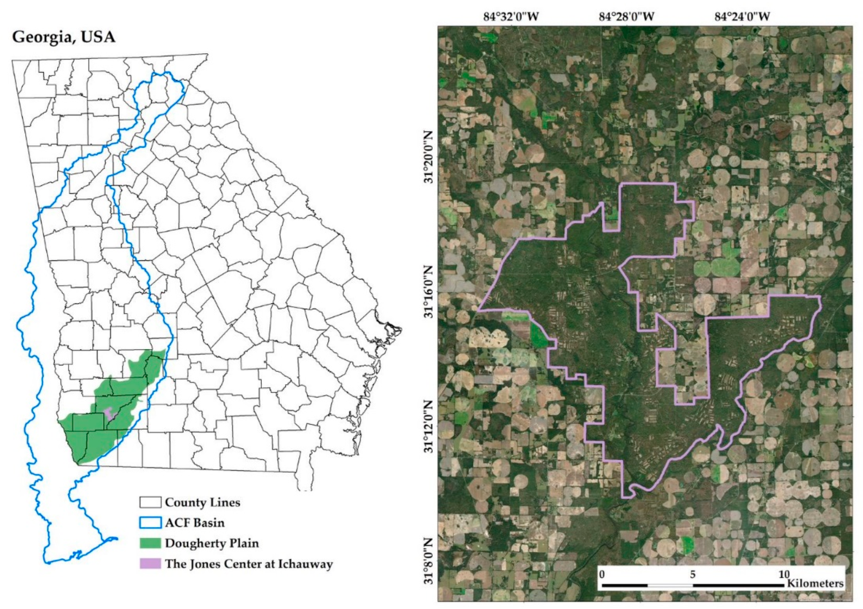
Figure 1. Maps showing the ACF basin, the Dougherty Plain, the Jones Center, and the study area. Latitude and Longitude coordinates: 31.220284, −84.478656.
Hydrology 09 00168 g001
Figure 2. (a) Locations of several GIWs, of two long GPR transects, and of the high-density GPR grid are shown overlain on LiDAR DTM [33]; (b) locations of the sinkhole lineament within the draw, the GPR transects (black lines) between them, and Ichawaynochaway Creek overlain on LiDAR DTM [33]. Select GPR lines are colored purple.
Hydrology 09 00168 g002aHydrology 09 00168 g002b
Figure 3. (a) GPR survey along the road separating Richardson Flat and Balden Pond. The left side of the image is the north end of the survey. The green line is the top of the soil. The yellow and purple lines outline areas of reflectors indicative of vuggy porosity indicated by weak (yellow) and strong (purple) reflectors; (b) select GPR image of the high-density grid over the sink point in Richardson Flat showing a high porosity zone, outlined in yellow. These images are normalized to depth. The feature is funnel-shaped and located below the lowest point of the pond; (c) cross-section showing topography and depths of features.
Hydrology 09 00168 g003aHydrology 09 00168 g003b
Figure 4. (a) GPR survey near the southwestern portion of the draw; green indicates the interpreted top of the soil surface, and purple indicates the interpreted top of epikarst surface. The yellow outline annotates what is interpreted as a sinkhole funnel that is yet to collapse; (b) GPR survey in the middle portion of the draw. The yellow dashed line indicates the boundaries of a possible cavity; (c) GPR survey along a road adjacent to the west bank of Ichawaynochaway Creek; the yellow outlines annotate interpreted the continuation of solution-enlarged fissures that are visible in outcropping from the stream. These fissures align with the documented fracture pattern in the region [6,7,25,26].
Hydrology 09 00168 g004aHydrology 09 00168 g004b
Figure 5. (a) The evolution of compound sinkholes (left) into a uvala (right), through enhanced dissolution along pre-existing fracture planes (orange lines). Modified from White [24]; (b) depiction of the small- and intermediate scale (according to Ford [22]) draw connectivity and evolution into the larger GIW sequence as a uvala.
Hydrology 09 00168 g005
Publisher’s Note: MDPI stays neutral with regard to jurisdictional claims in published maps and institutional affiliations.