Article

Using Heat as a Tracer to Detect the Development of the Recharge Bulb in Managed Aquifer Recharge Schemes

Institute of Life Sciences, Scuola Superiore Sant’Anna, 56122 Pisa, Italy
*
Author to whom correspondence should be addressed.
Hydrology 2022, 9(1), 14; https://doi.org/10.3390/hydrology9010014
Submission received: 12 December 2021 / Revised: 10 January 2022 / Accepted: 11 January 2022 / Published: 12 January 2022
(This article belongs to the Special Issue Integrated Surface Water and Groundwater Analysis)

Abstract

:
Managed Aquifer Recharge (MAR), the intentional recharge of aquifers, has surged worldwide in the last 60 years as one of the options to preserve and increase water resources availability. However, estimating the extent of the area impacted by the recharge operations is not an obvious task. In this descriptive study, we monitored the spatiotemporal variation of the groundwater temperature in a phreatic aquifer before and during MAR operations, for 15 days, at the LIFE REWAT pilot infiltration basin using surface water as recharge source. The study was carried out in the winter season, taking advantage of the existing marked difference in temperature between the surface water (cold, between 8 and 13 °C, and in quasi-equilibrium with the air temperature) and the groundwater temperature, ranging between 10 and 18 °C. This difference in heat carried by groundwater was then used as a tracer. Results show that in the experiment the cold infiltrated surface water moved through the aquifer, allowing us to identify the development and extension in two dimensions of the recharge plume resulting from the MAR infiltration basin operations. Forced convection is the dominant heat transport mechanism. Further data, to be gathered at high frequency, and modeling analyses using the heat distribution at different depths are needed to identify the evolution of the recharge bulb in the three-dimensional space.

1. Introduction

Freshwater resources are suffering from increasing pressure worldwide. Their contamination and overexploitation are compromising access to safe water [1,2,3]. This situation pushes towards the search for innovative ways to preserve and increase freshwater resources availability, focusing on sustainable water management techniques. Managed Aquifer Recharge (MAR), the intentional recharge of aquifers potentially using water from various sources, has surged worldwide in the last 60 years as one of these options [4,5,6,7].
Measurements of infiltration rates and groundwater levels variations, together with the estimation of the groundwater flows generated during recharge in MAR schemes, are used to evaluate the performance in terms of recharge volumes and the extension of the recharge plume [8,9]. Different groundwater monitoring techniques are usually implemented for this purpose, where the use of sensors to measure groundwater pressure head, electrical conductivity, temperature, and soil moisture is normally accompanied to groundwater sampling for chemical analyses and numerical modeling [10,11,12].
Ganot et al. [11] assessed the relation between the infiltration and the development of the groundwater mound in MAR using desalinated seawater in an infiltration pond. In their study, the saturated zone of the aquifer was monitored through two groundwater observation wells instrumented with pressure head and electrical conductivity loggers. These measurements were later used in a lumped model where the infiltration dynamics was analyzed to assess the temporal and spatial variation of the recharge. Likewise, the changes in recharge from a river into an aquifer as a result of the implementation of a Riverbank Filtration MAR scheme were evaluated by Rossetto et al. [12] by means of a multidisciplinary approach using hydrodynamics, hydrochemical, and modeling methods, following intensive sensors application [13].
New innovative methodologies to estimate the extension and development of the plume of recharged water in the aquifer are also being proposed. These methodologies apply geophysical methods and can range from the use of electrical resistivity [14,15,16,17] up to time-lapse gravity measurements [18,19].
The use of vertical electrical conductivity profiles for the estimation of the saturated hydraulic conductivity and the van Genuchten parameters under an infiltration pond was studied by Mawer et al. [14]. Similarly, Nenna et al. [15] used electrical resistivity probes with the objective of mapping and monitoring the recharge plume from an infiltration pond. By monitoring the temporal variation of the vertical electrical resistivity of different points located under and around the infiltration pond, the temporal variation of the water table could be estimated together with the hydraulic gradients. These data can be used later to estimate the fate of the recharged water. Haaken et al. [16] assessed the use of Electrical Resistivity Tomography (ERT) measurements for characterizing groundwater dynamics under a Soil Aquifer Treatment scheme. Zones with different hydraulic properties were identified by analyzing the temporal variations of these measurements. Likewise, García-Menéndez et al. [17] used ERT to evaluate the effectiveness of MAR in a coastal aquifer. With this technology, the extension and shape of the recharge plume could be identified. This was completed after the joint interpretation of the ERT images with Electrical Conductivity logs from boreholes, and with geological and hydrogeological information of the site. The use of time-lapse gravity surveys was assessed by Davis et al. [18] for the monitoring of an Aquifer Storage and Recovery (ASR) scheme. The use of this geophysical technology was applied successfully during the injection of water into the aquifer for the detection of the general distribution and movement of the injected water. With a similar approach, Chapman et al. [19] used high-precision gravity measurements for the monitoring of another ASR pilot system. In their study, the high-precision gravity surveys were carried before, during, and after two infiltration cycles. The detection of the formation of a mound of recharged groundwater during the recharge cycles was possible with the analysis of the collected data.
The fundamentals of the use of heat as a tracer in groundwater have been previously studied [20]. Groundwater temperature may be measured by lowering a thermometer down a borehole, and the wide availability of waterproof temperature loggers makes this parameter easily accessible [20,21]. Various experimental applications using heat carried by groundwater as a tracer to monitor different aspects of MAR operations have been investigated by diverse authors. For instance, a Fiber Optic Distributed Temperature Sensing technique was used to estimate infiltration rates from recharge basins [22,23]. Similarly, heat was also used as a tracer for the estimation of recharge rates at infiltration ponds [24], and for the estimation of travel time in bank filtration systems [25]. Likewise, the vertical fluxes in heterogeneous aquifers can be estimated using heat [26].
In this study, we monitored the spatio-temporal variation of the groundwater temperature in a phreatic aquifer before and during MAR operations, for 15 days, at a pilot infiltration basin. This change in groundwater temperature is being used to identify the development and extension of the resulting recharge plume following recharge operations at the LIFE REWAT MAR infiltration basin [27].

2. Materials and Methods
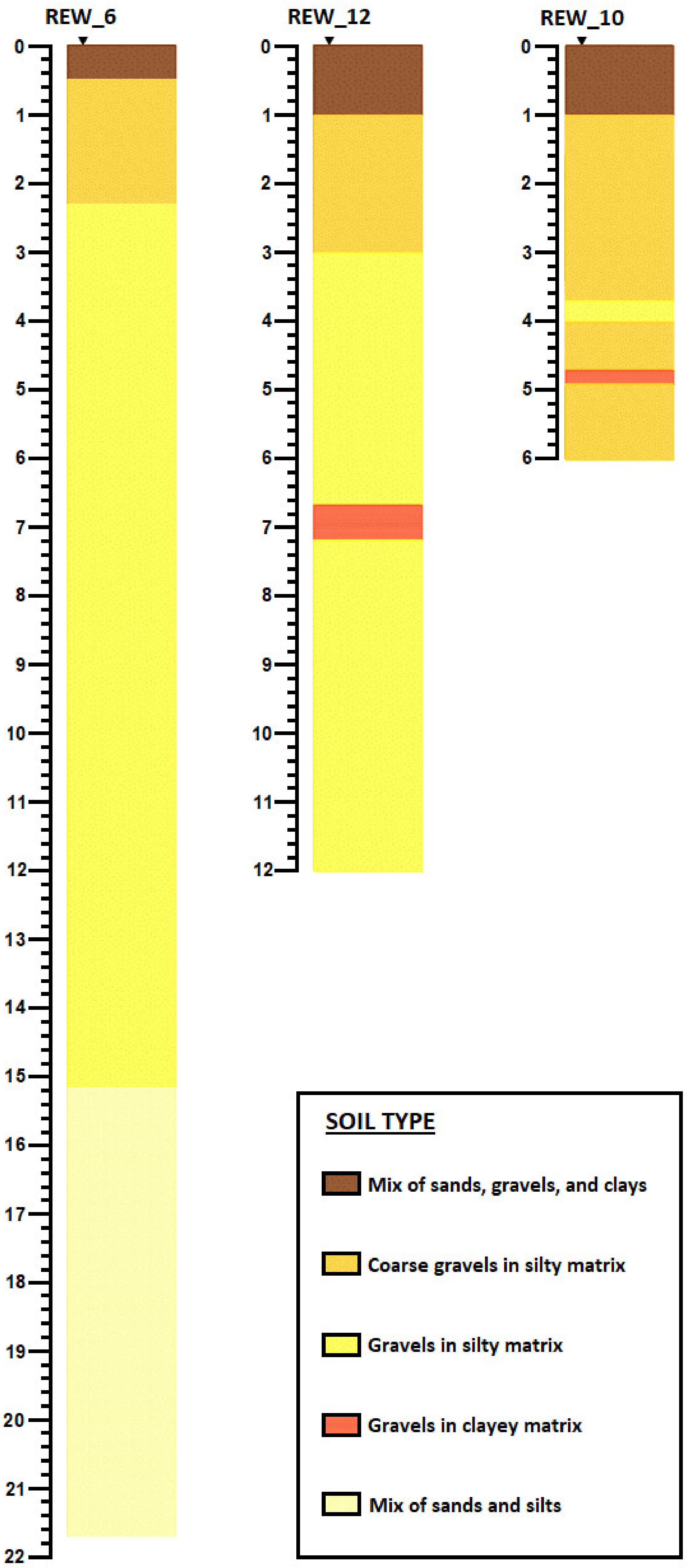
In this section, the study site and the MAR scheme are presented alongside the methodology used for monitoring the groundwater temperature changes. The operations at the LIFE REWAT MAR infiltration basin with its different components are also briefly described.

2.1. Study Site

The study site is located in the municipality of Suvereto (Tuscany, Italy) in the alluvial plain of the Cornia River (Figure 1). The Cornia plain hosts a Holocene coastal aquifer constituted by alluvial and swamp-lagoonal deposits. The deposits, largely influenced by the Cornia River dynamics, include gravel, sand, silt, and clay in different proportions and distributions. The stratigraphy of the aquifer under investigation is well presented in Barazzuoli et al. [28]. New drillings allow us to obtain new information confirming the previous hypotheses and work. A large proportion of the aquifer is composed of a gravel lithology in a silty–sandy matrix, possessing a prevalent permeability by interstitial porosity. This layer outcrops the surface or is covered by a layer of silt as a result of fluvial overflows. The aquifer is unconfined in the area of the infiltration basin. Large surface water–groundwater exchanges occur between the River Cornia and the aquifer.
Figure 2 presents the stratigraphies at points REW_10 (in the center of the infiltration basin), REW_12 and REW_6 (north of the infiltration basin). A relatively thin layer of agricultural soil covers an alternate layer of gravels with different size distribution in silty matrix in the vicinity of the infiltration basin up to about 15 m from soil surface. Some thin lenses of gravels in a clayey matrix can also be found at different depths. As such, the experimental area shows up to a depth of about 15 m from the soil surface, the presence of a gravel-dominated environment, in a matrix variable from silt to sand.
The River Cornia is the main hydrologic feature in the area. The high hydraulic conductivity of the riverbed provides high hydraulic connectivity between the surface water and the aquifer. This enhances surface and groundwater exchanges in the areas near to the river. Hence, the groundwater heads are controlled by the water level of the river, and, locally, by the presence of pumping wells. Because of this, values of electrical conductivity in the aquifer slightly differ from those of surface water. As such, the parameter electrical conductivity cannot be easily used to trace the recharged water. The main groundwater natural flow is directed towards the West, resulting from river recharge and inflows from adjoining hilly areas, with an average hydraulic gradient of 0.2% (Figure 3). From the regional hydrology point of view the area is a recharge area.
Additionally, the study area is characterized by the presence of an important hydrothermal system, which contributes to the recharge of the superficial aquifer by means of upward groundwater flow, causing some thermal and geochemical anomalies [28,29].
The initial temperature conditions in the aquifer at the beginning of the rainfall season (just after the end of the dry season), before the managed aquifer recharge operations started in 2019, can be seen in Figure 3. The local groundwater temperatures ranged between 15.7 and 19.6 °C in November 2019, with air temperature varying from 8 to 20 °C, and surface water temperature at about 15 °C in those days. A fairly homogeneous distribution of temperatures, higher than about 17 °C, is noticeable in the MAR scheme area. Two deeper points, REW_6 and REW_142, show temperatures of 17.1 and 18.8 °C, respectively (a map of temperature distribution only is available as Supplementary Materials, Figure S1). These relatively high groundwater temperatures highlight the presence of the above-mentioned geothermal flow.

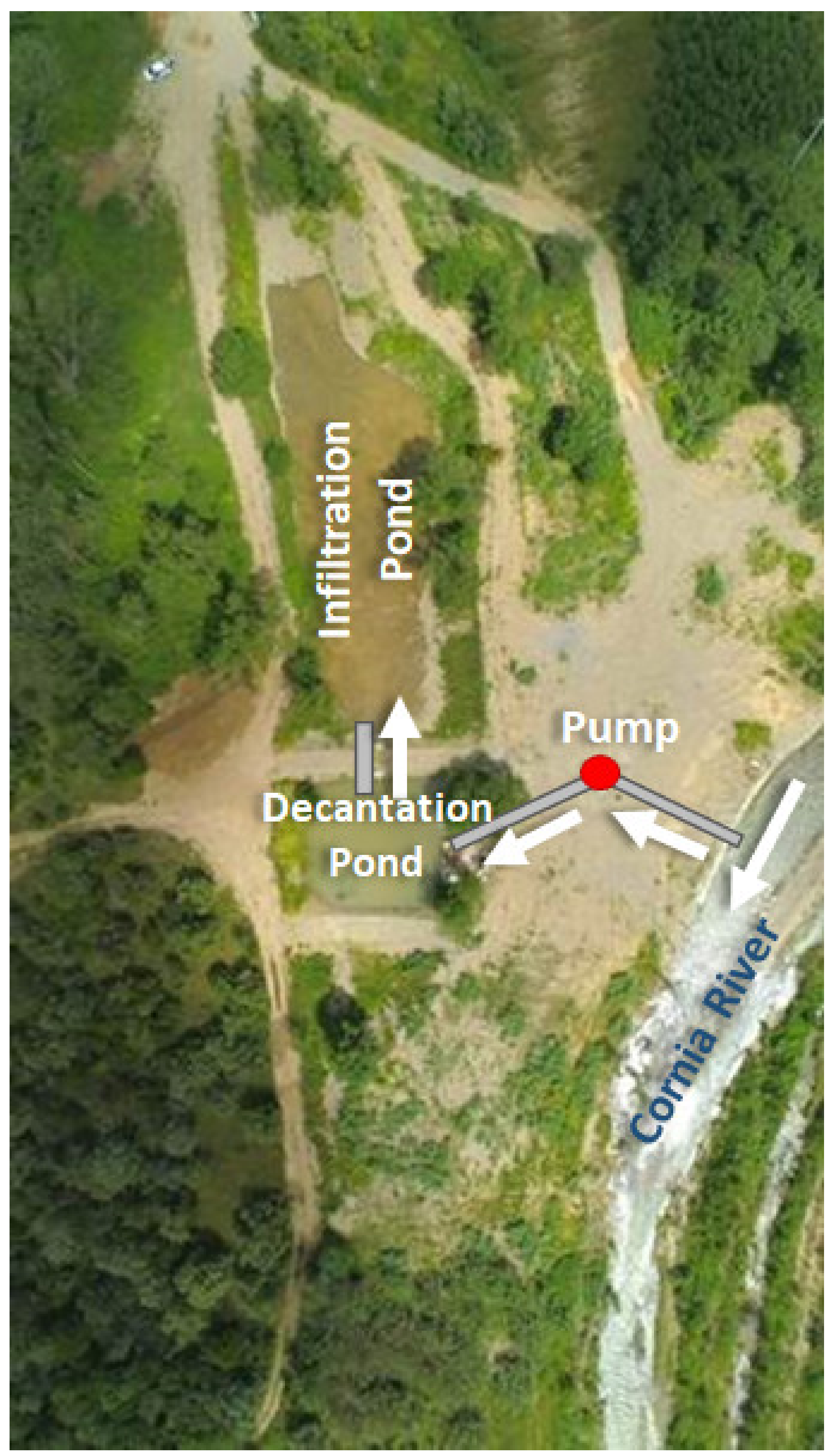
2.2. The LIFE REWAT Managed Aquifer Recharge Scheme

The LIFE REWAT Managed Aquifer Recharge scheme is a two-stage infiltration basin using harvested rainwater from the Cornia River during high-flow periods. The scheme consists of diversion infrastructure and then two basins: a settling pond and the infiltration basin (Figure 4). Surface water is firstly diverted from the Cornia river into the decantation pond, where the suspended solids are deposited. Afterwards, the water enters into the infiltration pond. The infiltration pond was constructed in a topographic low, where the soil (sandy/silty gravels) provides a full hydraulic connection with the phreatic aquifer.
The MAR scheme is operated using a hi-tech high-frequency automated and remotely controlled system, and quasi real-time monitoring of water quantity and quality is run. This system is supported by the data gathered from different sensors installed in the area, recording different parameters into a database with a frequency of fifteen minutes.

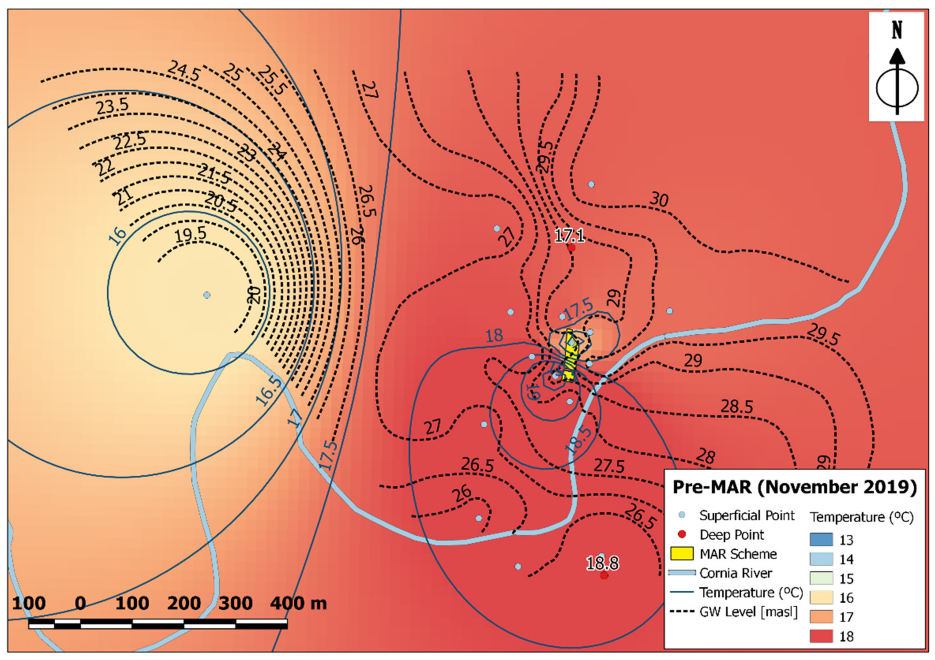
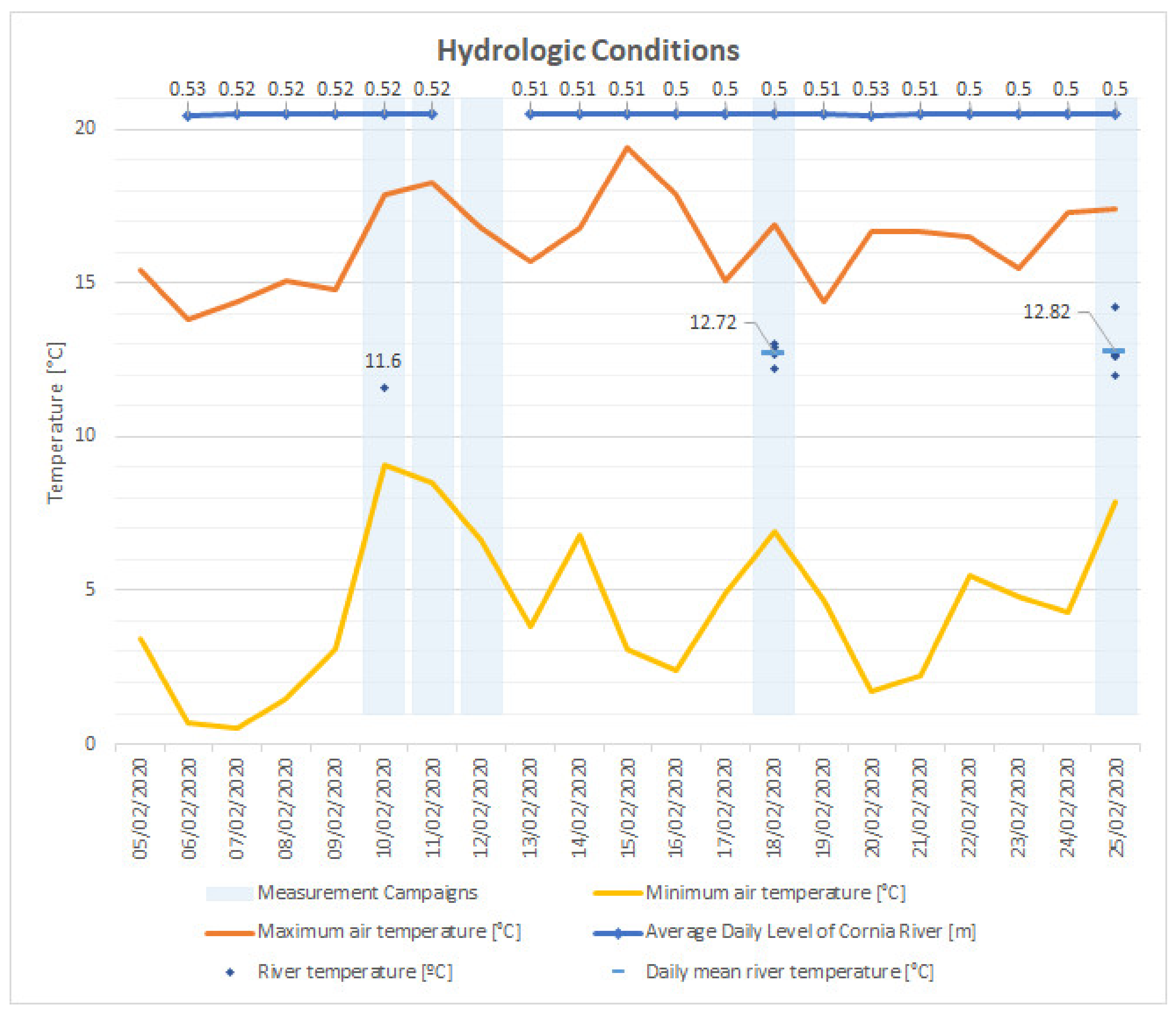
2.3. Groundwater Head and Temperature Monitoring

For this study, groundwater head and temperature were monitored at selected points in the shallow aquifer (Table 1 and Figure 1; shallow points are named “Superficial”). These points, located upstream and downstream of the MAR scheme, were monitored before and during MAR operations, covering two weeks of full operations of the MAR scheme. Deeper screened points (i.e., points at depths higher than 20 m; “Deep” points in Table 1) were also monitored (Figure 1), but their data are not used in the interpolation process, and only plotted against the temperature distribution in the shallow aquifer.
The fieldwork measurements were carried out with two instruments, a portable water level meter (dipper) [30], and a thermo-dipper [31]. The dipper had precision of 1 cm, while the temperature sensor had accuracy of ±0.1 °C ranging from −10 to +50 °C.
The study was carried out in winter, taking advantage of the existing difference in temperature between the surface water (cold, between 8 and 13 °C, and in quasi-equilibrium with the air temperature) and the groundwater. This way the colder surface water infiltrating in the basin could mix with/replace the warmer groundwater in the aquifer during the recharge operations. The experiment started on 9 February 2020. On that date at 15:00 (CET) the MAR scheme was set off for 52 h, being in full operation since 10 December 2019. On 11 February at 19:00 (CET) the scheme was turned on again. The temperature monitoring took place on three campaigns: C1 on 10 February 2020, and 11 February 2020; C2 on 18 February 2020; C3 on 25 February 2020. The experiment ended because of a large flooding event of the Cornia River occurring on 3 March 2020, when the managed recharge was temporarily suspended following operational protocols. During the experiment, we approximately recharged the aquifer at the rate of 5800 m3/day.
Groundwater heads and temperatures were measured at 27 points in the phreatic aquifer and at 4 points at depth larger than 20 m from soil surface (Table 1). In order to avoid measuring the temperature of the groundwater superficially, hence subjectedto short-time changes in air temperature, the temperature measurements were taken from depths under 5 m of the water level if the depth of the piezometers allowed it. The measured values of heads and temperatures were finally spatially interpolated utilizing the Inverse Distance Weight interpolation feature of QGis 2.18.28 [32] and then some isolines were slightly modified to take the influence of the River Cornia into account. Additionally, water levels and temperature variations from different points were recorded automatically through a series of sensors in situ. All these values were recorded in the SCADA system of the MAR scheme with a frequency of fifteen minutes.
The meteo-climatic and hydrologic conditions were monitored during the experiment period and are summarized in Figure 5. The air temperature ranged between a minimum value of 0.5 °C and a maximum value of 19.4 °C, with an average value of 10.4 °C for the whole period [33]. Similarly, the water temperature from the Cornia River presented a mean value of 12.7 °C. The experiment was run with the river level remaining in baseflow conditions, at a constant level of 0.51 m, varying 1 or 2 cm during the day, at the Ponte per Montioni monitoring station [34]. During the study period, 3 days of rainfall were recorded, where only a total of 1.8 mm of rainfall was recorded on 19 February 2020 and 0.2 mm on 20 February 2020 and 24 February 2020, respectively (recorded at the rain gauge station of Suvereto) [35]. The amount of rainfall is therefore considered negligible in term of aquifer recharge affecting the experiment.

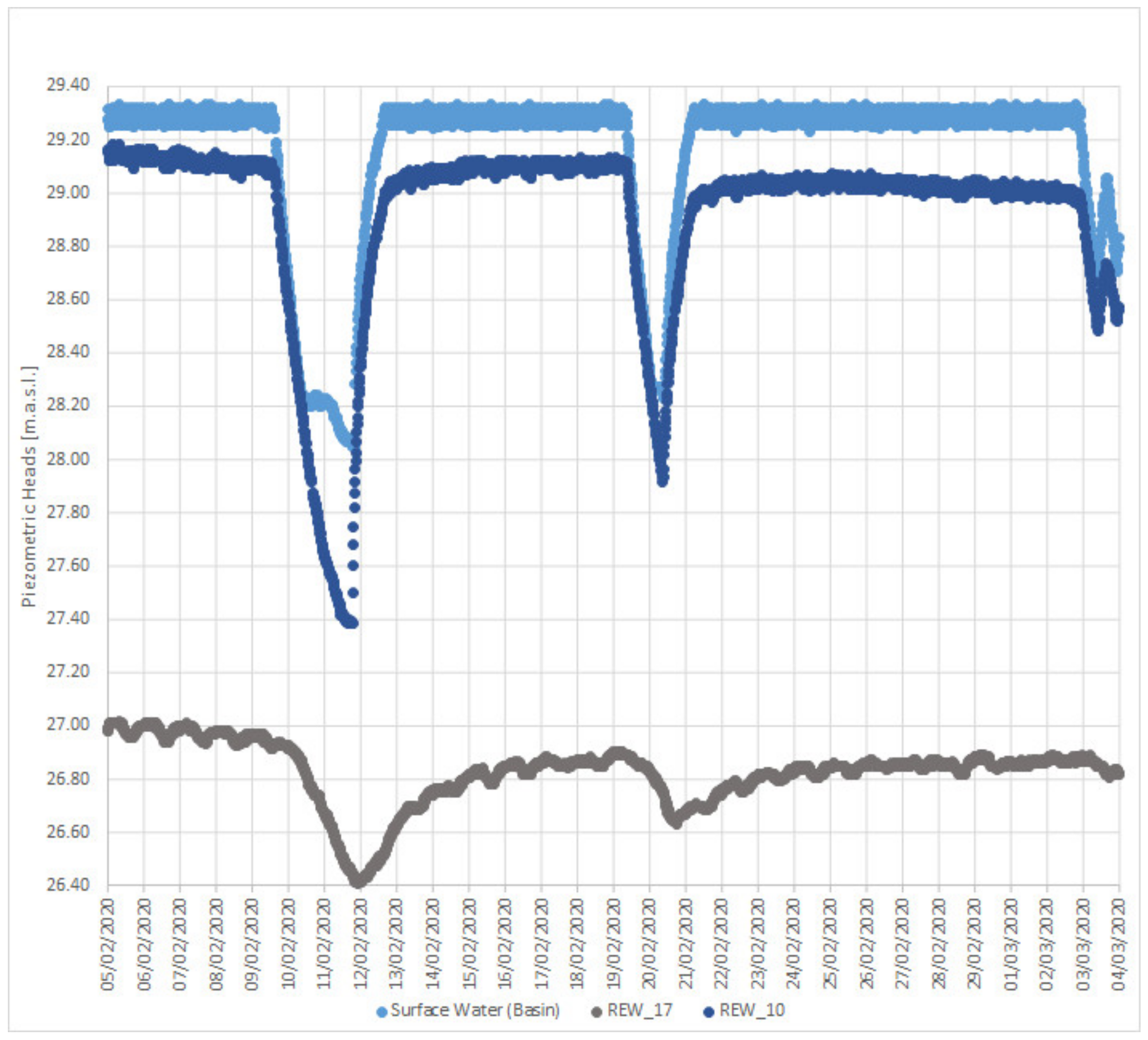
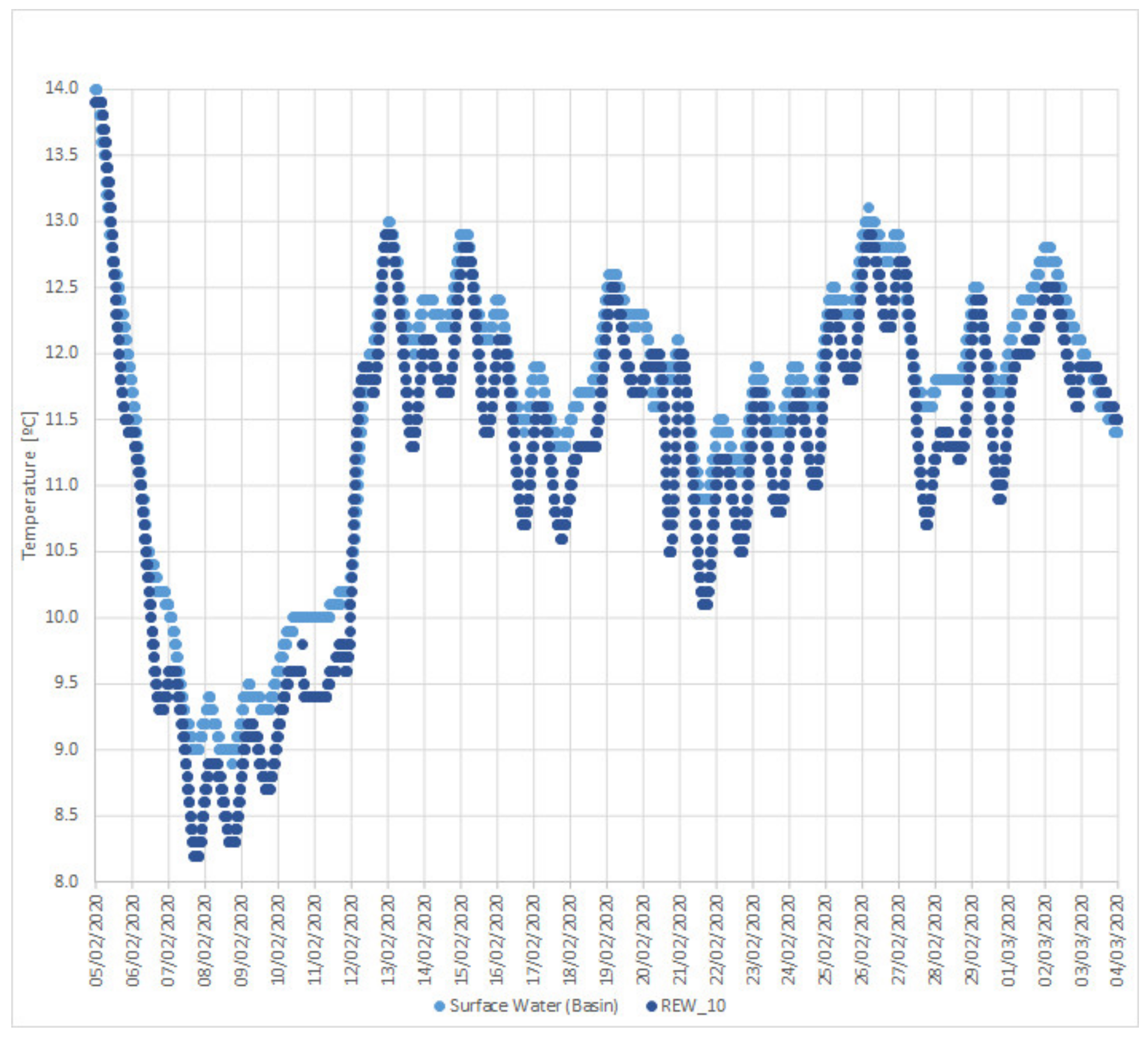
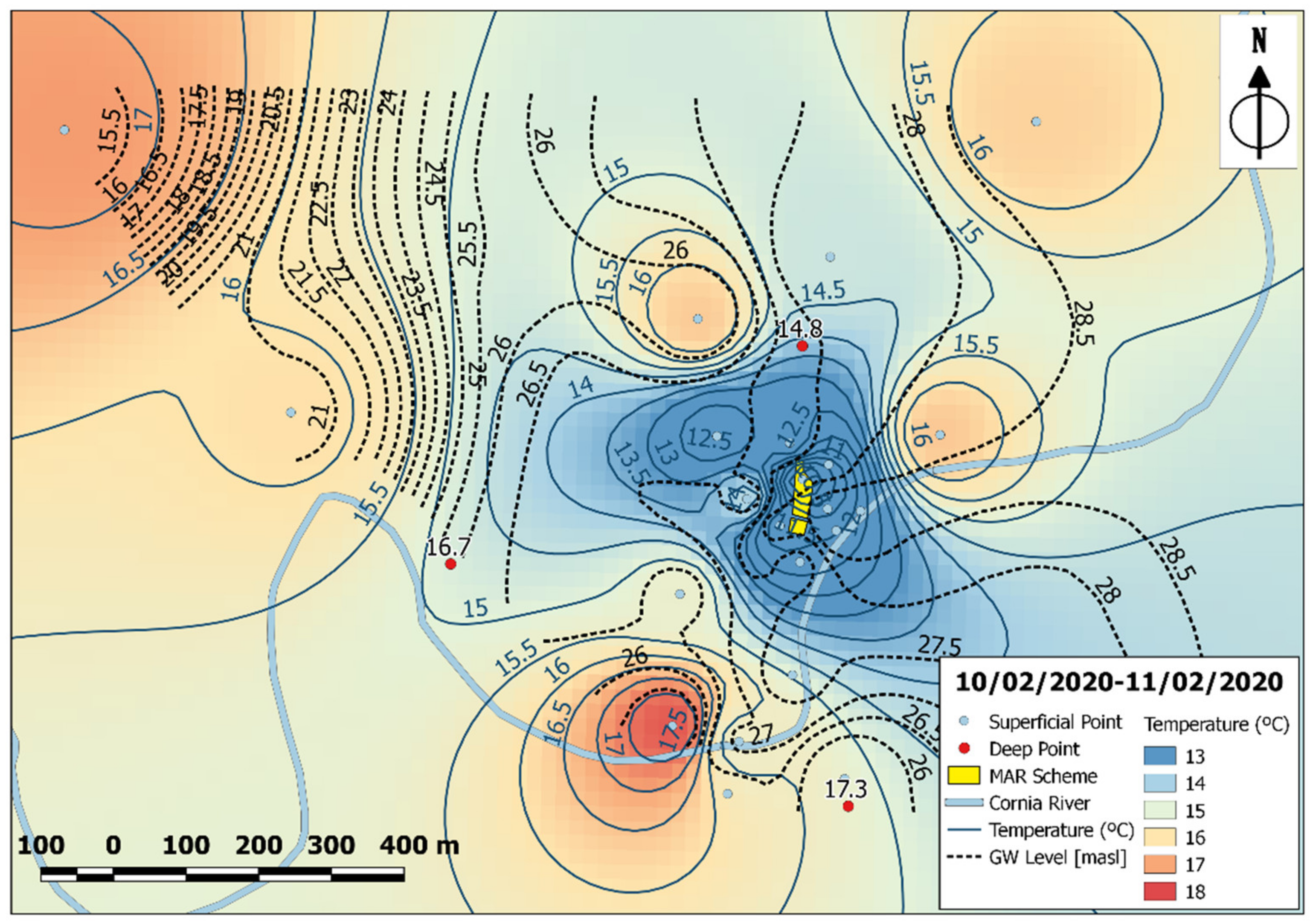
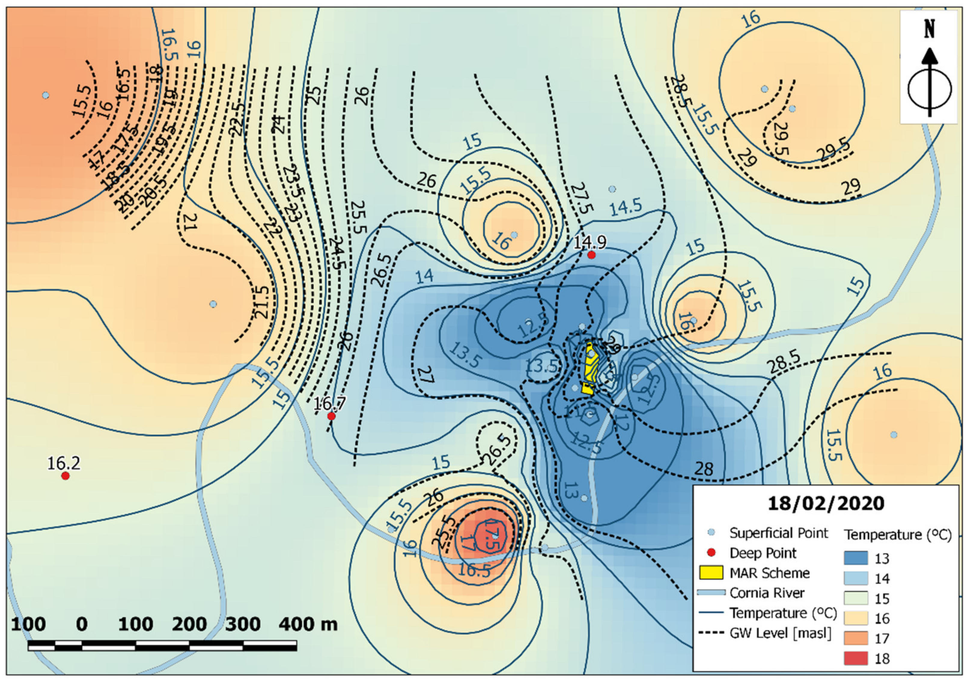
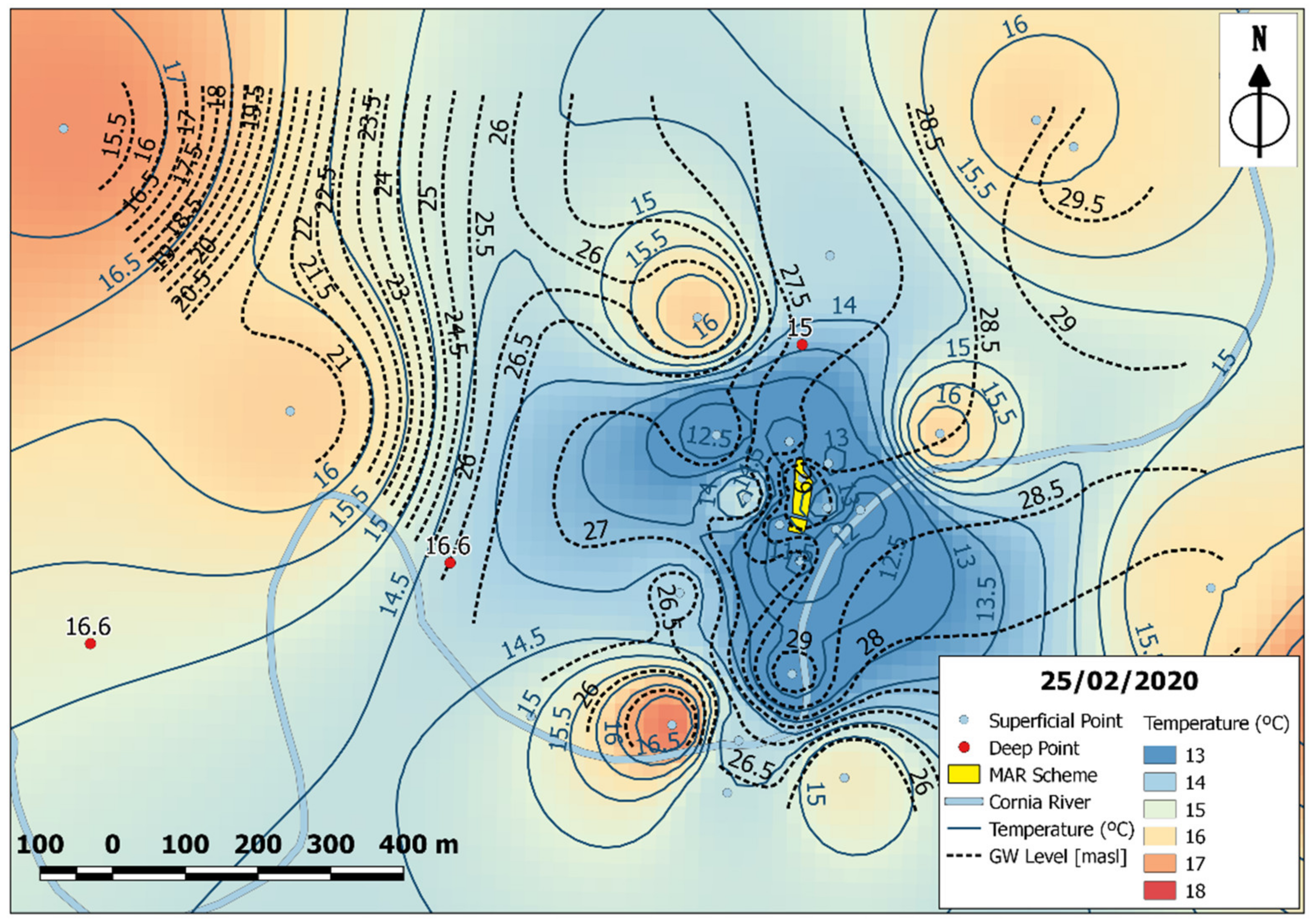
3. Results and Discussion

In Figure 6, the discharge curve of the infiltration basin together with the piezometric variations at the points REW_10, located in the infiltration basin, and REW_17 are presented. The 52 h interruption of the recharge operations, from 9 until 11 February 2020, was reflected in the water level of the infiltration basin and in the aquifer. Another short interruption of the recharge operations is also observable from 19 until 20 February 2020 as a result of the automatic operation of the scheme. The changes in the basin water level are reflected in a relatively short time in nearby points (e.g., the point REW_17, located around 150 m downstream of the infiltration basin). This behavior cannot be explained solely by the Darcy equation of flow in porous media, but on the analysis of the speed of the pressure wave (celerity) [36,37,38]. Thus, the hydraulic head changes in the groundwater may not accurately represent the actual movement of the recharged water volume itself. Therefore, complementary information, such as those provided by heat carried by groundwater, and analyses are required for the determination of the development of the recharged plume.
The temperature variations of the surface water in the infiltration basin, and of the groundwater at the point REW_10, screened at 2.7 m depth under the infiltration basin, can be seen in Figure 7. The change in temperature reflected on the groundwater point is in direct relation with the changes in the surface-water temperature in the infiltration basin. The temperature differences between these two points are relatively small. This relation suggests a displacement of the native groundwater by the infiltrated one or a mix of these two endmembers, with a dominant surface-water component.
The existing temperature in the aquifer after 2 months of MAR operations, and shortly before the described experiment started, is shown in Figure 8 (the map of temperature distribution only is available as Supplementary Materials, Figure S2). Compared to November 2019 (Figure 3), a cold area centered in the recharge basin (REW_10 at 9.6 °C) has developed following two main axes: one towards West and one approximately South.
The MAR operations slightly modify the regional groundwater flow by superimposing two local, additional mainly East to West and North to South flow to the dominant in the area river recharge. A high thermal gradient is detected within the first 100 m around the infiltration basin. In our experiment, the groundwater flow perturbed the geothermal gradient by infiltration of relatively cool water in a recharge area contrasting with an upward flow of relatively warm water. Recharge is clearly affecting the aquifer temperature in the infiltration basin area.
Comparing Figure 8 with Figure 3, the points located on the North–East, upstream of the infiltration basin, hold a steady temperature above 16 °C, as seen before the recharge activities. This shows a very slow change in their temperature with time, in contrast with the areas directly impacted by the MAR activities. At the shallow point, REW_158, the temperature stays high at 17.8 °C. The same applies to the deeper points, REW_444, West of the basin, at 16.7 °C, and REW_142, at 17.3 °C, demonstrating the relevance of the geothermal flow in this section. The colder plume depicted South of the river is a result of the interpolation process, and no data are available to confirm these results.
Once the MAR operations restarted, on 11 February at 19.00 (CET) a cold temperature plume further developed following the above-mentioned directions. When observing the variation with time of the values of groundwater temperatures in Figure 9 and in Figure 10 (maps of temperature distribution only are available as Supplementary Materials, Figures S3 and S4), it is worth noting that the temperatures of the points located upstream of the infiltration basin (REW_19, REW_5, REW_3, and REW_30) still maintain constant values. This shows a minor development of the recharge bulb upstream of the MAR scheme, and the relevance in the area of a forced convection heat transport in agreement with the modified groundwater flow direction.
The temperature signal seems undetectable at REW_23, about 700 m West of the recharge area, while REW_158 still maintains a temperature higher than 17 °C. In this regard, two hypotheses may be made: (i) the recharge flow did not reach these points during the experiment time, and/or (ii) the upward geothermal warm flow potentially has a larger influence. In the second case, recharged groundwater would be mixing with the geothermal flow, but the rate of recharged water during the experiment would be low compared to the geothermal flow, then being unable to change the aquifer thermal state. Taking the area enclosed within the 14 °C isotherm in the northern side of the Cornia River as a reference, this area expands with time. Starting with 110,000 m2 on 11th February, the area grew up to 138,000 m2 after 7 days, and up to 174,000 m2 after 14 days.
Because of the imposed head gradient in the MAR area, forced convection [20] seems to be the dominant heat transport mechanism in our experiment, while minor relevance seems to have conduction and transport with thermal dispersivity.

4. Conclusions

The experiment described here shows the use of heat carried by groundwater as a tracer in order to detect the development of the recharge plume in a Managed Aquifer Recharge scheme. As our experiment demonstrated, heat as a tracer is especially suited for delineating small-scale flow paths monitoring temperature in the aquifers [39]. Temperature, besides hydraulic head and groundwater chemistry data, is a readily available parameter that, in particular meteo-climatic conditions, may provide cost-effective observations to conduct hydrological investigations. Results show that in the experiment the cold-infiltrated surface water moves through the aquifer, allowing us to identify the development and extension in the two-dimensional space of the recharge plume resulting from the LIFE REWAT MAR infiltration basin operations. The results highlight two main components of convective heat transport, one towards the West and one to the South, forced by the hydraulic gradient set by the recharge operations. The upstream groundwater flow seems to limit the cold water movement on the eastern side of the MAR scheme. The recharge operations seem not to affect the deeper layers of the aquifer. Further analyses are needed to evaluate the mixing between the groundwater of geothermal origins and the recharged one.
Further works will include the assessment of heat transport in 2D along a cross-section monitoring temperature (with other parameters) at different depths of the aquifer. The joint use of groundwater head and temperature data in 3D groundwater modeling applications may support the parameterization of the aquifer system under investigation and the set-up of geochemical reactive transport models for the understanding of complex processes occurring during recharge. Finally, we suggest that along other parameters to be analyzed during the planning, design and investigation phase of Managed Aquifer Recharge schemes [40,41], groundwater temperature distribution is duly considered in order to accurately estimate groundwater flow direction and velocities prior to the modified state and following the beginning of MAR operations.

Supplementary Materials

The following supporting information can be downloaded at: https://www.mdpi.com/article/10.3390/hydrology9010014/s1, Figure S1: Groundwater temperature before MAR operations started. From 25 November 2019 to 27 November 2019. Figure S2: Groundwater temperature distributions with MAR operations halted for the experiment (10–11 February 2020). Figure S3: Groundwater temperature distribution after 7 days since restart of MAR operations (18 February 2020). Figure S4: Groundwater temperature distribution after 14 days since the restart of MAR operations (25 February 2020).

Author Contributions

Conceptualization, E.C. and R.R.; methodology, E.C. and R.R.; formal analysis, E.C.; investigation, E.C. and M.A.; resources, R.R.; data curation, E.C.; writing—original draft preparation, E.C. and R.R.; writing—review and editing, E.C. and R.R.; visualization, E.C.; supervision, R.R.; project administration, R.R.; funding acquisition, R.R. All authors have read and agreed to the published version of the manuscript.

Funding

This paper is presented within the framework of the MARSoluT ITN project (www.marsolut-itn.eu) (accessed on 10 December 2021). and the EU LIFE REWAT project (www.liferewat.eu) (accessed on 10 December 2021). The MARSoluT project receives funding from the European Union’s Horizon 2020 research and innovation programme under the Marie Skłodowska-Curie grant agreement no. 814066. The LIFE REWAT project received funding from the European Union’s Life Programme LIFE 14 ENV/IT/001290.

Acknowledgments

The authors wish to thank ASA spa (Mirko Brilli, Claudio Benucci and Patrizio Lainà) and Consorzio di Bonifica 5 Toscana Costa (Alessandro Fabbrizzi, Roberto Benvenuto and Giancarlo Vallesi) for technical support at the MAR scheme. E.C. performed the research as ESR6 PhD student in the MARSOLUT project. M.A (now at Studio Geologico Rafanelli) participated to this research as a post-graduate scholarship.

Conflicts of Interest

The authors declare no conflict of interest.

References

  1. Arnell, N.W. Climate change and global water resources. Glob. Environ. Chang. 1999, 9, S31–S49. [Google Scholar] [CrossRef]
  2. European Environment Agency. Water Use and Environmental Pressures. 2020. Available online: https://www.eea.europa.eu/themes/water/european-waters/water-use-and-environmental-pressures/water-use-and-environmental-pressures (accessed on 30 December 2020).
  3. Leduc, C.; Pulido-Bosch, A.; Remini, B. Anthropization of groundwater resources in the Mediterranean region: Processes and challenges. Hydrogeol. J. 2017, 25, 1529–1547. [Google Scholar] [CrossRef]
  4. Dillon, P. Future management of aquifer recharge. Hydrogeol. J. 2005, 13, 313–316. [Google Scholar] [CrossRef]
  5. Dillon, P.; Stuyfzand, P.; Grischek, T.; Lluria, M.; Pyne, R.D.G.; Jain, R.C.; Bear, J.; Schwarz, J.; Wang, W.; Fernandez, E.; et al. Sixty years of global progress in managed aquifer recharge. Hydrogeol. J. 2019, 27, 1–30. [Google Scholar] [CrossRef] [Green Version]
  6. Wintgens, T.; Hochstrat, R.; Kazner, C.; Jeffrey, P.; Jefferson, B.; Melin, T. Managed Aquifer Recharge as a Component of Sustainable Water Strategies-A Brief Guidance for EU Policies. In Water Reclamation Technologies for Safe Managed Aquifer Recharge; IWA Publishing: London, UK, 2012; pp. 411–429. [Google Scholar]
  7. Fernandez Escalante, E.; Henao Casas, J.D.; Vidal Medeiros, A.M.; San Sebastián Sauto, J. Regulations and guidelines on water quality requirements for Managed Aquifer Recharge. International comparison. Acque Sotter. Ital. J. Groundw. 2020, 9, 7–22. [Google Scholar] [CrossRef]
  8. Prathapar, S.; Dhar, S.; Rao, G.T.; Maheshwari, B. Performance and impacts of managed aquifer recharge interventions for agricultural water security: A framework for evaluation. Agric. Water Manag. 2015, 159, 165–175. [Google Scholar] [CrossRef]
  9. Maliva, R.G. Managed aquifer recharge: State-of-the-art and opportunities. Water Sci. Technol. Water Supply 2015, 15, 578–588. [Google Scholar] [CrossRef]
  10. Bundschuh, J.; Sracek, O. Introduction to Groundwater Geochemistry and Fundamentals of Hydrogeochemical Modelling; Taylor & Francis Group: Abingdon, UK, 2012. [Google Scholar]
  11. Ganot, Y.; Holtzman, R.; Weisbrod, N.; Nitzan, I.; Katz, Y.; Kurtzman, D. Monitoring and modeling infiltration-recharge dynamics of managed aquifer recharge with desalinated seawater. Hydrol. Earth Syst. Sci. 2017, 21, 4479–4493. [Google Scholar] [CrossRef] [Green Version]
  12. Rossetto, R.; Barbagli, A.; De Filippis, G.; Marchina, C.; Vienken, T.; Mazzanti, G. Importance of the Induced Recharge Term in Riverbank Filtration: Hydrodynamics, Hydrochemical, and Numerical Modelling Investigations. Hydrology 2020, 7, 96. [Google Scholar] [CrossRef]
  13. Rossetto, R.; Barbagli, A.; Borsi, I.; Mazzanti, G.; Vienken, T.; Bonari, E. Site investigation and design of the monitoring system at the Sant’Alessio Induced RiverBank Filtration plant (Lucca, Italy). Rend. Online Soc. Geol. Ital. 2015, 35, 248–251. [Google Scholar] [CrossRef]
  14. Mawer, C.; Kitanidis, P.; Pidlisecky, A.; Knight, R. Electrical resistivity for characterization and infiltration monitoring beneath a managed aquifer recharge pond. Vadose Zone J. 2013, 12, vzj2011.0203. [Google Scholar] [CrossRef]
  15. Nenna, V.; Pidlisecky, A.; Knight, R. Monitoring managed aquifer recharge with electrical resistivity probes. Interpretation 2014, 2, T155–T166. [Google Scholar] [CrossRef]
  16. Haaken, K.; Furman, A.; Weisbrod, N.; Kemna, A. Time-Lapse Electrical Imaging of Water Infiltration in the Context of Soil Aquifer Treatment. Vadose Zone J. 2016, 15, 1–12. [Google Scholar] [CrossRef]
  17. García-Menéndez, O.; Ballesteros, B.J.; Renau-Pruñonosa, A.; Morell, I.; Mochales, T.; Ibarra, P.I.; Rubio, F.M. Using electrical resistivity tomography to assess the effectiveness of managed aquifer recharge in a salinized coastal aquifer. Environ. Monit. Assess. 2018, 190, 100. [Google Scholar] [CrossRef]
  18. Davis, K.; Li, Y.; Batzle, M. Time-lapse gravity monitoring: A systematic 4D approach with application to aquifer storage and recovery. Geophysics 2008, 73, WA61–WA69. [Google Scholar] [CrossRef]
  19. Chapman, D.S.; Sahm, E.; Gettings, P. Monitoring aquifer recharge using repeated high-precision gravity measurements: A pilot study in South Weber, Utah. Geophysics 2008, 73, WA83–WA93. [Google Scholar] [CrossRef] [Green Version]
  20. Anderson, M.P. Heat as a ground water tracer. Groundwater 2005, 43, 951–968. [Google Scholar] [CrossRef]
  21. Banks, D. From Fourier to Darcy, from Carslaw to Theis: The analogies between the subsurface behaviour of water and heat. Acque Sotter. Ital. J. Groundw. 2012, 1, 3. [Google Scholar] [CrossRef] [Green Version]
  22. Becker, M.W.; Bauer, B.; Hutchinson, A. Measuring artificial recharge with fiber optic distributed temperature sensing. Groundwater 2013, 51, 670–678. [Google Scholar] [CrossRef]
  23. Mawer, C.; Parsekian, A.; Pidlisecky, A.; Knight, R. Characterizing heterogeneity in infiltration rates during managed aquifer recharge. Groundwater 2016, 54, 818–829. [Google Scholar] [CrossRef]
  24. Racz, A.J.; Fisher, A.T.; Schmidt, C.M.; Lockwood, B.S.; Huertos, M.L. Spatial and temporal infiltration dynamics during managed aquifer recharge. Groundwater 2012, 50, 562–570. [Google Scholar] [CrossRef]
  25. des Tombe, B.F.; Bakker, M.; Schaars, F.; van der Made, K.J. Estimating travel time in bank filtration systems from a numerical model based on DTS measurements. Groundwater 2018, 56, 288–299. [Google Scholar] [CrossRef] [Green Version]
  26. Kurylyk, B.L.; Irvine, D.J.; Carey, S.K.; Briggs, M.A.; Werkema, D.D.; Bonham, M. Heat as a groundwater tracer in shallow and deep heterogeneous media: Analytical solution, spreadsheet tool, and field applications. Hydrol. Processes 2017, 31, 2648–2661. [Google Scholar] [CrossRef]
  27. Rossetto, R.; De Filippis, G.; Borsi, I.; Foglia, L.; Cannata, M.; Criollo, R.; Vázquez-Suñé, E. Integrating free and open source tools and distributed modelling codes in GIS environment for data-based groundwater management. Environ. Model. Softw. 2018, 107, 210–230. [Google Scholar] [CrossRef]
  28. Barazzuoli, P.; Bouzelboudjen, M.; Cucini, S.; Király, L.; Menicori, P.; Salleolini, M. Olocenic alluvial aquifer of the River Cornia coastal plain (southern Tuscany, Italy): Database design for groundwater management. Environ. Geol. 1999, 39, 123–143. [Google Scholar] [CrossRef] [Green Version]
  29. Celati, R.; Grassi, S.; D’Amore, F.; Marcolini, L. The low temperature hydrothermal system of Campiglia, Tuscany (Italy): A geochemical approach. Geothermics 1991, 20, 67–81. [Google Scholar] [CrossRef]
  30. PASI. Portable Groundwater Level Meter. Freatimetro. 2021. Available online: https://www.pndshop.it/dt/ct20183/art201821/freatimetro-bfk (accessed on 10 December 2021).
  31. PASI. Portable Groundwater Level and Thermo Meter. Termofreatimetro. 2021. Available online: https://www.pndshop.it/dt/ct20183/art201823/freatimetro-wmf-02 (accessed on 10 December 2021).
  32. QGIS Development Team. QGIS Geographic Information System. Open Source Geospatial Foundation Project. 2021. Available online: http://qgis.osgeo.org (accessed on 11 December 2021).
  33. Servizio Idrologico e Geologico della Regione Toscana. Settore Idrologico e Geologico Regionale. DATI Termometria. 2021. Available online: https://www.sir.toscana.it/termometria-pub (accessed on 10 December 2021).
  34. Servizio Idrologico e Geologico della Regione Toscana. Settore Idrologico e Geologico Regionale. DATI Idrometria. 2021. Available online: https://www.sir.toscana.it/idrometria-pub (accessed on 10 December 2021).
  35. Servizio Idrologico e Geologico della Regione Toscana. Settore Idrologico e Geologico Regionale. DATI Pluviometria. 2021. Available online: https://www.sir.toscana.it/pluviometria-pub (accessed on 10 December 2021).
  36. Chesnaux, R. Avoiding confusion between pressure front pulse displacement and groundwater displacement: Illustration with the pumping test in a confined aquifer. Hydrol. Processes 2018, 32, 3689–3694. [Google Scholar] [CrossRef]
  37. Verseveld, W.J.V.; Barnard, H.R.; Graham, C.B.; McDonnell, J.J.; Brooks, J.R.; Weiler, M. A sprinkling experiment to quantify celerity–velocity differences at the hillslope scale. Hydrol. Earth Syst. Sci. 2017, 21, 5891–5910. [Google Scholar] [CrossRef] [PubMed] [Green Version]
  38. Worthington, S.R.; Foley, A.E. Deriving celerity from monitoring data in carbonate aquifers. J. Hydrol. 2021, 598, 126451. [Google Scholar] [CrossRef]
  39. Giambastiani, B.M.S.; Colombani, N.; Mastrocicco, M. Limitation of using heat as a groundwater tracer to define aquifer properties: Experiment in a large tank model. Environ. Earth Sci. 2012, 70, 719–728. [Google Scholar] [CrossRef]
  40. Barbagli, A.; Jensen, B.N.; Raza, M.; Schueth, C.; Rossetto, R. Assessment of soil buffer capacity on nutrients and pharmaceuticals in nature-based solution applications. Environ. Sci. Pollut. Res. 2019, 26, 759–774. [Google Scholar] [CrossRef]
  41. NRMMC; EPHC; NHMRC. Australian Guidelines for Water Recycling, Managing Health and Environmental Risks, Vol 2C: Managed Aquifer Recharge; Natural Resource Management Ministerial Council, Environment Protection and Heritage Council National Health and Medical Research Council: Australia, 2009; 237 p. Available online: http://www.environment.gov.au/water/publications/quality/water-recycling-guidelines-mar-24.html (accessed on 8 January 2022).
Figure 1. Study area location and measured points.
Hydrology 09 00014 g001
Figure 2. Stratigraphy of three piezometers near the infiltration basin. Information obtained from the analysis of the soil cores during the construction of these piezometers.
Hydrology 09 00014 g002
Figure 3. Groundwater temperature distribution in the aquifer before MAR operations started. Data taken from 25 November 2019 to 27 November 2019.
Hydrology 09 00014 g003
Figure 4. LIFE REWAT Managed Aquifer Recharge scheme.
Hydrology 09 00014 g004
Figure 5. Hydrologic conditions at the MAR site during the experiment.
Hydrology 09 00014 g005
Figure 6. Recorded piezometric heads from in-situ sensors (m above mean sea level).
Hydrology 09 00014 g006
Figure 7. Recorded surface and groundwater temperature variations in the infiltration basin.
Hydrology 09 00014 g007
Figure 8. Groundwater temperature distribution with MAR operations halted for the experiment.
Hydrology 09 00014 g008
Figure 9. Groundwater temperature distribution after 7 days of the restart of MAR operations.
Hydrology 09 00014 g009
Figure 10. Groundwater temperature distribution after 14 days of the restart of MAR operations.
Hydrology 09 00014 g010
Table 1. List of the piezometers and wells used in the experiment.
PointPiezometer TypeMonitored Depth [m]Point Depth [m]PointTypeMonitored Depth [m]Point Depth [m]
REW_10Superficial2.702.80REW_39Superficial15.0015.50
REW_11Superficial5.006.14REW_3Superficial10.0012.00
REW_12Superficial8.0011.84REW_5Superficial5.906.00
REW_13Superficial6.006.50REW_6Deep10.0030.00
REW_14Superficial6.156.23REW_119Superficial10.0012.00
REW_15Superficial6.106.25REW_142Deep40.0043.00
REW_16Superficial4.905.00REW_156Superficial3.904.00
REW_17Superficial6.007.05REW_157Superficial5.505.60
REW_18Superficial6.806.90REW_158Superficial5.205.25
REW_19Superficial8.508.88REW_301Superficial2.003.76
REW_20Superficial14.6014.70REW_302Superficial1.602.88
REW_23Superficial13.0014.00REW_304Superficial1.503.71
REW_24Superficial8.008.16REW_305Superficial4.004.94
REW_25Superficial7.007.57REW_306Superficial4.104.15
REW_30Superficial10.0012.00REW_444Deep20.0030.00
REW_36Deep21.0030.00----
Publisher’s Note: MDPI stays neutral with regard to jurisdictional claims in published maps and institutional affiliations.

