Abstract
Rainfall simulators are research devices that can be used for studying runoff and sediment transport on the plot scale. This technical note introduces a new solution that combines the two most commonly used methods for generating artificial rain—swinging and pulse jet systems. Reasons for developing this device are its universal use, simple construction, and reduction of water consumption, with better spatial distribution of rain and rainfall kinetic energy close to that of natural conditions. Routine operations of this device are expected for plots of 1 × 1 m, with a height 2–2.5 m. The rained surface could be extended to 2 × 2 m with lower spatial distribution. The sprinkled area in this case was limited by the drain box that also collected the remaining water. The principle of the presented single-nozzle simulator can be extended to multi-nozzle simulators for larger experimental plots.
1. Introduction
Modelling of rainfall–runoff processes with sediment transport depends on reliable data. Short and intensive rainfall events are temporally and spatially distributed and can be difficult to predict. This is the main reason why rainfall simulators (RS) can allow scientists to obtain data much more easily, with initial and boundary conditions under control. RS were designed in the USA in 1932 [1]. Since the 1950s, many types of RS with various sizes and from different developers have been produced. New improvements are driven by the technological progress following new findings in climatology, hydrology, and soil science. Many types of RS were published [2,3,4,5,6,7,8,9,10]. Some of the devices were also compared to each other [11]. Rain simulators are used for monitoring not only erosion processes on agricultural land, but also in line constructions [12]. The main characteristics of RS are the uniformity of the rain and kinetic energy affecting rain intensity. To characterize uniformity the Christiansen uniformity index (CU) is used [13]. This rainfall characteristics can now be monitored with disdrometers that effectively monitor the generated raindrop sizes and their kinetic energy [14]. Although artificial rain has some physical limitations (e.g., fall height, terminal velocity and kinetic energy, shape of artificial drops), knowledge of boundary conditions and their repeatability is essential [11].
Two main principles of raindrop generation are often used, i.e., (a.) without artificially induced pressure—free fall type, sometimes named drop-former RS [15]—and (b.) under pressure. The raindrops are formed in the free fall type on the outlet of thin holes or tubes. The raindrop velocity relies on the height of the structure, which is limiting for the operation of RS. The most used is a system that generates precipitation using a nozzle and pressured water. These types of RS can be used as mobile outdoor simulators and simulators with a large rained area. Water pressure in combination with the type of nozzle is essential for drop size distribution and velocity. Intermittent sprinkling, which allows adjusting rainfall intensity, is mostly ensured by means of (i.) a pulse-spray square nozzle (ii.) a swing flat jet covering the nozzle (iii.) a rotating disc covering the nozzle in an interval scheme. The sprinkled area may be further extended by using multiple jets or a movable arm. In areas that lack or have less accessible water resources, maximum water saving is essential for the routine use of RS. Spraying only a defined space and recycling the excess water significantly save water.
This technical note introduces a new solution that combines the two most commonly used methods for generating artificial rain—swinging and pulse jet systems. Reasons for developing this device are its universal use, simple construction, reduction of water with better spatial distribution of rain, and rainfall kinetic energy close to the natural conditions.
2. Materials and Methods
The design was based on combining the swinging of the nozzle with interruptions. Classical pulse-spray rainfall simulators only allow closing and opening of the valve to supply water to the nozzle. The authors’ experience in the calibration and selection of nozzles for simulators [7] indicates that nozzles do not guarantee uniform spraying, as the shape of the sprinkled area changes at the same setting of pressure and angular rotation of the nozzle. Flat spray nozzles generally offer higher uniformity of coverage but, on the other hand, they are devices with a constant flow of water through the nozzle that make it difficult to recycle the water.
2.1. Sprinkling Head Technical Design Concept
The design concept of the new simulator includes the option of adding a hollow shaft for water intake mounted in bearings to the water supply, to which the nozzle, housing a solenoid valve and a pressure sensor, is connected. The connection with the stepper motor is supplied by a Cardan joint, which allows small clearances that occur during field work, transport, and other handling operations. The stepper motor is fitted with a zero-position sensor from which the inclination angle of the nozzle can be read. At the same time, it is possible to determine in which phase of the nozzle rotation the solenoid valve should be open or shut off.
The closing and opening of the valve and the operation of the stepper motor are controlled by a control unit, which must allow the following settings: return to zero position, inclination angle, movement velocity, lag time to the next sequence, and valve opening lag time from the start of movement.
The sprinkling head itself, which is shown in Figure 1, consists of fixed parts and moving parts. Numbers in the following text are the parts marked in Figure 1. The main fixed parts include a watertight-mounted stepper motor 1, nozzle rotation basic position 5 is set on the fixed part by sensor 2 of motor zero position 1. These elements, including drain box 7, are mounted on the supporting element 11, which is connected by fixtures 12 to supporting legs 18. The fixed and moving parts are interconnected by bearings 4 and Cardan joint 10, which balances slight angular rotations and angles that must be eliminated in field conditions. The moving part is fitted with the position contactor 3, which determines the motor zero position 1. Nozzle 5 is replaceable by means of the bayonet connector 6 with a holder to which water flows by a hollow shaft 8 connected to the water supply 16 by a flexible connector 9. T-joint 13 on water supply 16 houses a pressure sensor 17, and beam 15 houses a solenoid valve 14, which is controlled in parallel with the rotating nozzle 5.
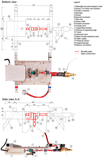
Figure 1.
Drawings and photos of the rainfall simulator sprinkling head. Bottom view and side view of the rainfall simulator sprinkling head. Moving parts are marked in red, dimensions are in mm.
2.2. Drain Box
The technical design concept includes a box for catching excess water during the oscillating movement of the nozzle (No.7 in Figure 1). The box is a rectangular case housing a quadrilateral pyramid with a hole (Figure 2). The water that does not pass through the hole is drained back into the tank by an overflow hose. The box can be placed at different distances from the nozzle using adjusting screws. This makes it possible to adjust the size of the sprinkled surface area and recycle excess sprays outside the sprinkled surface area back into the tank.
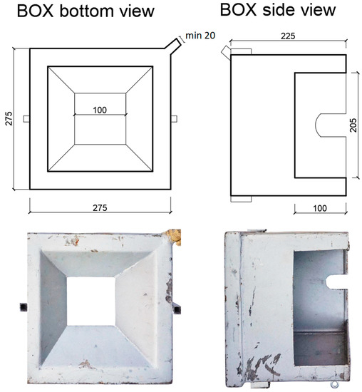
Figure 2.
Box for catching excess water.
The purpose of this box is to delimit the required size of the sprinkled area and eliminate unwanted overspray outside the monitored area. Excess water is drained from the box back into the water tanks. The delimitation of the sprinkled area not only serves to save water, but also increases the sprinkler operator’s comfort. The drain box has a square plan of 27.5 × 27.5 cm and is fitted with 22.5 cm high walls on the outside. The internal part is a regular truncated quadrilateral pyramid with a base with an edge of 21.5 cm, a height 6.5 cm, and an angle of 140°. The distance from nozzle 5 is adjustable, thus allowing restricting the sprinkled area. The water is drained through a hole with a diameter of 20 mm back into the tank. In the case of a smaller diameter, the water drainage capacity is exceeded at low intensities, and the drain box overflows. The drainage box can be made from steel or from transparent plastic to control water in the box.
2.3. Control Unit and Power Supply
The control unit (CU) of the whole system allows the setting and selection of precipitation scenarios. The scenario is based on (a) defining the velocity and angle of rotation of the stepper motor oscillating movement, (b) the simultaneous opening and closing of the solenoid valve, (c) the length of the pause. For individual scenarios, the simulation length and the follow-up scenario are further presented. Ten scenarios can be in use. The option of choosing a follow-up scenario allows the simulation with variable rainfall intensities. The length of the pause then determines the rain intensity. The control unit also controls the second solenoid valve, which is switched to a reverse mode and is mounted on the circulation pipe. If the valve on the simulator sprinkler head is in the OFF position, the solenoid valve on the circulation pipe is in the ON position and vice versa. This provides protection against overpressure in the system.
The control unit also allows a stationary position of the nozzle without any movement. In this mode, the simulator can be used as a classical pumped rainfall simulator.
Among suitable nozzles, that with a minimum guaranteed pump flow per nozzle of 12 l/min was chosen. Both 12 and 24 V DC pumps with a battery power supply were tested, but this solution proved to be inconvenient due to the capacity of the batteries and their weight. The selected power source was 220 V AC and 12 (24) DC V. Low voltage is necessary for both the operating staff safety and the efficient operation of the solenoid valve and the stepper motor.
Part of the technical design concept is also a bayonet connector for a potential exchange of nozzles. Flat and square spray nozzles can be used.
2.4. Methodology of Jet Selection
Square nozzles can be used for both pulse and swipe system, while flat nozzles can only be used for the swipe system. The choice of the nozzle is also important in terms of rainfall characteristics. The basic characteristics are (a) raindrop terminal velocity, (b) drop size distribution (DSD), (c) kinetic energy (Ke) calculated from these mentioned values, (d) rainfall spatial distribution. The development phase of the device involved the testing of various nozzles, both in terms of sprinkling uniformity and in terms of kinetic energy, i.e., the distribution of raindrop size and their terminal velocity.
Tests to select the best nozzles, which can provide sufficient spatial distribution and kinetic energy similar to those of natural rainfall, were performed in laboratory conditions. Firstly, the rainfall spatial distribution was tested gravimetrically using 15 × 15 cm sampling buckets at a spacing of 25 cm, so that the area of these buckets would occupy one-third of the total sprinkled area. Uniformity was successively assessed as described [13]. Nozzles that obtained a CU higher than 70% were subsequently tested for kinetic energy. Fall velocity, DSD, and Ke were measured using the Thies LPM disdrometer [16] in five positions, which is shown in Figure 3. Positions were settled to obtain the mean values for the whole experimental plot. In every position, five 1 min intervals were measured, and the mean value was calculated. There was no delimitation by Ke for the future use of the selected nozzles.
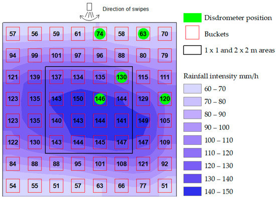
Figure 3.
Example of rainfall spatial distribution for the nozzle Veejet 80100. The experiment was conducted without gaps. Presented is the maximal possible intensity for this nozzle. The numbers in the boxes indicate rainfall intensity in mm/h at the specified location.
3. Results and Discussion
The functionality and usability of the device were tested in terms of rainfall uniformity and Ke of the raindrops. The resulting parameters of the nozzles and the generated rainfall characteristics are presented in Table 1. In total, six flat nozzles and one square nozzle presented a CU higher than 70%. In Figure 3, an example of rainfall spatial distribution (nozzle Veejet 80100) is shown. The green spots indicate where the disdrometer was placed.

Table 1.
List of tested nozzles. VJ—VeeJet nozzles provide a flat water jet. WSQ provide a square water jet. The nozzles marked with * are suitable for further use. The WSQ 40 nozzle was tested in a stationary position also with swipe. For VJ 9540 and VJ 9560 nozzles, Ke values were not measured, as the required uniformity of 70% was not achieved with these nozzles.
Different heights of the nozzle above the surface have different effects on the performance. When the nozzle is high above the surface, the spatial distribution of rainfall is usually better, and the kinetic energy of the drops is closer to that of natural rainfall. On the other hand, equipment handling and the stability of the supporting construction (especially against wind and due to swinging of the nozzle) are more challenging. For this head of rainfall simulator, we aimed for device height of approximately 2–2.5 m. Previously, we found no difference in kinetic energy between systems with a height of 2 m and 2.5 m when testing the nozzle WSQ 40 in the stationary system [7].
Christiansen Uniformity Index
The values of the CU of the tested nozzles are presented in Table 1. The applicable nozzles in the table marked with an asterisk (*) present the previously described features. Bliesner and Keller [17] classified irrigation uniformity as good when CU is over 84%; according to Little et al. [18], these nozzles can be classified as very good or good. All these nozzles are of the flat type. For the tested square nozzle, an increase in oscillating motion was noticeable, especially, if the swinging system was used for a rainy area of 2 × 2 m, when the increase of CU was more than 14%. The best tested nozzle was Veejet 80100, with a CU of 97% for an area of 1 m2 and a CU of 71% for an area of 4 m2. The second option was the square nozzle WSQ40, which can provided a CU of 79% on a plot of 1 m2, but on a plot of 4 m2, the CU was 74 %. Both nozzles showed also the highest Ke values among all tested nozzles.
The CU essentially indicates how much of an area (in %) is covered by sampling buckets [19]. Usually, for a small rainfall simulator with plots up to 0.3 m2, the CU can be measured using a detailed scheme [20], but for plots with an area >1 m2 it is not possible to measure the CU with this scheme. The total area of the boxes was 72% of the total tested area (2x2m) in this study.
Kinetic energy of raindrops
The tested nozzles with the required spatial distribution had values between 3.97 and 10.38 J/m2/mm, measured by Thies LPM. Moreover, the measurement of raindrop sizes and velocities presented a high level of uncertainty due to substantial differences in the results provided by individual devices [16]. The value of Ke closest to that of natural rainfall was measured for the nozzles Veejet 80100 and WSQ40, which provided also a very good spatial distribution.
The kinetic energy of artificial rainfall is lower compared to that of natural precipitations of same intensity; this is a known drawback of rainfall simulators in general [21]. Van Dijk et al. [22] presented a review of worldwide measurements of drop sizes, rainfall intensities, and kinetic energies, and Coutinho et al. [23] presented a study based on measurements in Portugal. Based on this research, the range of the KE is very wide, approximately 15–35 J/m2/mm, and the higher values occur during rainfalls with a high rainfall intensity.
Compared to other similar devices, the proposed design of a rainfall simulator has a few new advantages. We compared it to other jet-type simulators and it´s not possible to compare it with simulators based on different rainfall generation (e.g. free fall) which are designed for different research tasks. The often used small rainfall simulator presented by Iserloh [18] is suitable for a small experimental plot less than 1 m2 and has one nozzle, without the possibility of setting different rainfall intensities (it is only possible to change the nozzle). A similar new rainfall simulator presented by Salem and Meselhy [24]. It can produce a maximal rainfall intensity of 80 mm/h on a plot of 1.4 m2. This device has higher kinetic energy than the RS presented in this work, but it could be of limited use, only for the simulation of extreme rainfall events with intensity higher than 80 mm/h. Its fall height is 3 m, which is a high value for use in a field for routine operation. In addition, wind protection could be difficult.
Compared to the rainfall simulators presented by Iserloh [11], the device presented here is suitable for a larger experimental plot with similar falling height of the raindrops. Users of the device can choose the required nozzle for their specific research task. In addition, they can set the intensity in a wide range without changing other parameters of rainfall because of the pulse or swing system.
One of the innovative features of simulation in modelling natural processes is the possibility of automatically triggering different successive scenarios. Therefore, variable rainfall intensities can be simulated. This is an important parameter allowing a wider use of rain simulators and the achievement of conditions similar to natural processes [25].
4. Conclusions
Dozens of rainfall simulators have been designed in recent years. The devices presented offer an innovative solution for artificial rainfall generation in erosion and hydrological research. Their development and calibration are costly and time-consuming. Sharing information on the development of new approaches will make it possible to streamline and share measured values. The uniqueness of our design concept, which combines the properties of swing and pulse artificial rain generation, enables exploiting to the full the benefits of these two principles.
A square nozzle can be used without a swinging system. The benefits of the swipe are displayed by the WSQ 40 nozzle that shows an improvement in CU, especially on an area of 2 × 2 m.
The tested nozzles described in this article are definitely not the only usable nozzles. Testing nozzles is time-consuming, and their development was focused mainly on nozzles suitable for a 1 × 1 m experimental area. Therefore, flat spray nozzles with a spray angle of 95° were selected. It would also be possible to use nozzles with a spray angle of 110°.
The technical design concept comprised the description of the testing method, which included both spatial uniformity and total intensity measured on an impermeable substrate and the measured kinetic energy of rainfall.
A single-nozzle rainfall simulator was described. The used principle of oscillating movement in combination with interruptions can also be applied in larger simulators where more nozzles with solenoid valves will be mounted on one oscillating shaft. With three nozzles (VeeJet) at a distance of 1.33 m, it is possible to achieve a rained area of 4 × 2 m (area 8 m2) with a spatial distribution Cu = 84.8 and a maximum intensity of 144 mm/h with the same Ke. The maximum rainfall intensity was recalculated based on a 2 m area measurement considering nozzle overspray (places reached by rainfall from two nozzles).
The control unit was designed to allow the basic control of the system. It was built using the RS-485 proprietary protocol and is thus ready for potential control by an external control system (laptop, smartphone), which can provide easy-to-use control.
The head of the simulator is described in this article. Other required material necessary for field rainfall simulations was not included. The weight of the device is 12.5 kg. The supporting construction has to be made from solid material to provide enough support and avoid movements of the simulator due to swinging and the wind. The weight together with the swinging movement of the nozzles, requires a relatively solid structure, which ideally serves as a frame for wind protection. Steel or aluminum frame was used for the presented prototype. Light materials (Carbon or Kevlar based) can be used to obtain a lighter construction.
A height of 2.5 m is the best compromise for a suitable spatial distribution of the flat nozzles and the handling of the device. A 2 meter height is enough for the square nozzle WSQ 40 with adequate characteristics of the rainfall. In the field, a blanket or another material is necessary to avoid the influence of the wind, which can carry drops out of the experimental plot. During the simulation, the head of the simulator has to be in a horizontal position to provide uniform rainfall over the plot, and the nozzle has to be placed in the center of the plot. To center the nozzle lead is used, but cheap new technologies allow us to use a laser beam.
The power supply for the water pump is also crucial. In the first experiments, a 24 V water pump with lead battery was used. No water pump for 24 V was found to provide enough pressure and flow in combination with regular batteries for selected nozzles. A 220 V water pump with power station provided a good performance. Based on the tested nozzles, a flow of 12 L/s with a pressure of 2 bar is required for the nozzle Veejet 80100.
Author Contributions
P.K. and M.N. participated in testing and conducting measurements on the small rainfall simulator and writing this article together. All authors have read and agreed to the published version of the manuscript.
Funding
This research received no external funding.
Acknowledgments
This research was supported by the Technology Agency of the Czech Republic (grant numbersTH02030428 and TJ02000234) and by the Czech Ministry of Agriculture (grant number QK1910029) and by the Grant Agency of the Czech Technical University in Prague, grant No. SGS 20/156/OHK1/3T/11.
Conflicts of Interest
The authors declare no conflict of interest and the funders had no role in the design of the study; in the collection, analyses, or interpretation of data; in the writing of the manuscript, or in the decision to publish the results.
References
- Nichols, M.L.; Sexton, H.D. A method of studying soil erosion. Agric. Eng. 1932, 13, 101–103. [Google Scholar]
- Norton, L.D.; Savabi, R. Evolution of a linear variable intensity rainfall simulator for surface hydrology and erosion studies. Appl. Eng. Agric. 2010, 26, 239–245. Available online: http://www.scopus.com/inward/record.url?eid=2-s2.0-77951212833&partnerID=tZOtx3y1 (accessed on 22 April 2020). [CrossRef]
- Ries, J.B.; Seeger, M.; Iserloh, T.; Wistorf, S.; Fister, W. Calibration of simulated rainfall characteristics for the study of soil erosion on agricultural land. Soil Tillage Res. 2009, 106, 109–116. [Google Scholar] [CrossRef]
- Cerdà, A.; Ibáñez, S.; Calvo, A. Design and operation of a small and portable rainfall simulator for rugged terrain. Soil Technol. 1997, 11, 163–170. [Google Scholar] [CrossRef]
- Aksoy, H.; Unal, N.E.; Cokgor, S.; Gedikli, A.; Yoon, J.; Koca, K.; Inci, S.B.; Erisc, E. A rainfall simulator for laboratory-scale assessment of rainfall-runoff-sediment transport processes over a two-dimensional flume. Catena 2012, 98, 63–72. [Google Scholar] [CrossRef]
- Lassu, T.; Seeger, M.; Peters, P.; Keesstra, S.D. The Wageningen Rainfall Simulator: Set-up and Calibration of an Indoor Nozzle-Type Rainfall Simulator for Soil Erosion Studies. Land Degrad. Dev. 2015, 26, 604–612. [Google Scholar] [CrossRef]
- Kavka, P.; Strouhal, L.; Jáchymová, B.; Krása, J.; Báčová, M.; Laburda, T.; Dostál, T.; Devátý, J.; Bauer, M. Double size fulljet field rainfall simulator for complex interrill and rill erosion studies. Stavební Obz. Civ. Eng. J. 2018, 27, 183–194. [Google Scholar] [CrossRef]
- Kavka, P.; Neumann, M.; Laburda, T.; Zumr, D. Developing of the laboratory rainfall simulator for testing the technical soil surface protection measures and droplets impact. In Proceedings of the XVII ECSMGE-2019 European Conference on Soil Mechanics and Geotechnical Engineering, Reykjavik, Iceland, 1–6 September 2019. [Google Scholar] [CrossRef]
- Mhaske, S.N.; Pathak, K.; Basak, A. A comprehensive design of rainfall simulator for the assessment of soil erosion in the laboratory. Catena 2019, 172, 408–420. [Google Scholar] [CrossRef]
- Strauss, P.; Pitty, J.; Pfeffer, M.; Mentler, A. Rainfall Simulation for Outdoor Experiments. In Current Research Methods to Assess the Environmental Fate of Pesticides; INRA Editions: Versailles, France, 2000; pp. 329–333. [Google Scholar]
- Iserloh, T.; Ries, J.B.; Arnáez, J.; Boix-Fayos, C.; Butzen, V.; Cerdà, A.; Echeverría, M.T.; Fernández-Gálvez, J.; Fister, W.; Geißler, C.; et al. European small portable rainfall simulators: A comparison of rainfall characteristics. Catena 2013, 110, 100–112. [Google Scholar] [CrossRef]
- ASTM D6460-19 Standard Test Method for Determination of Rolled Erosion Control Product (RECP) Performance in Protecting Earthen Channels from Stormwater-Induced Erosion. Available online: https://www.astm.org/Standards/D6460.htm (accessed on 22 April 2020).
- Christiansen, J.E. Irrigation by Sprinkling. Univ. Calif. Agric. Exp. Stn. Bull. 1942, 670, 124. [Google Scholar]
- Zumr, D.; Mützenberg, D.V.; Neumann, M.; Jeřábek, J.; Laburda, T.; Kavka, P.; Johannsen, L.L.; Zambon, N.; Klik, A.; Strauss, P.; et al. Experimental Setup for Splash Erosion Monitoring—Study of Silty Loam Splash Characteristics. Sustainability 2020, 12, 157. [Google Scholar] [CrossRef]
- Cottenot, L.; Courtemanche, P.; Nouhou-Bako, A.; Darboux, F. A rainfall simulator using porous pipes as drop former. Catena 2021, 200, 105101. [Google Scholar] [CrossRef]
- Johannsen, L.L.; Zambon, N.; Strauss, P.; Dostal, T.; Neumann, M.; Zumr, D.; Cochrane, T.A.; Klik, A. Impact of disdrometer types on rainfall erosivity estimation. Water 2020, 12, 963. [Google Scholar] [CrossRef]
- Keller, J.; Bliesner, R.D. Sprinkle and Trickle Irrigation; Springer: Boston, MA, USA, 1990; Available online: https://repository.lboro.ac.uk/articles/conference_contribution/Christiansen_revisited_Rethinking_quantification_of_uniformity_in_rainfall_simulator_studies_Abstract_/9486149/1 (accessed on 22 April 2020).
- Little, G.E.; Hills, D.; Hanson, B. Uniformity in pressurized irrigation systems depends on design, installation. Calif. Agric. 1993, 47, 18–21. [Google Scholar] [CrossRef]
- Green, D.; Pattison, I. Christiansen Revisited: Rethinking Quantification of Uniformity in Rainfall Simulator Studies. In EGU General Assembly Conference Abstracts; EGU: Munich, Germany, 2016. [Google Scholar]
- Iserloh, T.; Fister, W.; Seeger, M.; Willger, H.; Ries, J.B. A small portable rainfall simulator for reproducible experiments on soil erosion. Soil Tillage Res. 2012, 124, 131–137. [Google Scholar] [CrossRef]
- Zambon, N.; Johannsen, L.L.; Strauss, P.; Dostal, T.; Zumr, D.; Cochrane, T.A.; Klik, A. Splash erosion affected by initial soil moisture and surface conditions under simulated rainfall. Catena 2021, 196, 104827. [Google Scholar] [CrossRef]
- van Dijk, A.I.J.M.; Bruijnzeel, L.A.; Rosewell, C.J. Rainfall intensity–kinetic energy relationships: A critical literature appraisal. J. Hydrol. 2002, 261, 1–23. [Google Scholar] [CrossRef]
- Coutinho, M.A.; Tomás, P.P. Characterization of raindrop size distributions at the Vale Formoso Experimental Erosion Center. Catena 1995, 25, 187–197. [Google Scholar] [CrossRef]
- Salem, H.M.; Meselhy, A.A. A portable rainfall simulator to evaluate the factors affecting soil erosion in the northwestern coastal zone of Egypt. Nat. Hazards 2021, 105, 2937–2955. [Google Scholar] [CrossRef]
- Dunkerley, D. Effects of rainfall intensity fluctuations on infiltration and runoff: Rainfall simulation on dryland soils, Fowlers Gap, Australia. Hydrol. Process. 2012, 26, 2211–2224. [Google Scholar] [CrossRef]


Publisher’s Note: MDPI stays neutral with regard to jurisdictional claims in published maps and institutional affiliations. |
© 2021 by the authors. Licensee MDPI, Basel, Switzerland. This article is an open access article distributed under the terms and conditions of the Creative Commons Attribution (CC BY) license (https://creativecommons.org/licenses/by/4.0/).