Abstract
Determining the type and properties of saturated groundwater for complex sedimentary facies, as well as the various properties of these sedimentary facies, requires extensive geological, hydrogeological, and geophysical studies. Therefore, identifying the different types of subsurface deposits and their physical properties as well as their geological, hydrogeological, and structural settings are the interesting features in this study which play an important role in achieving its objectives. To achieve these objectives, the Direct Current (DC) resistivity method and the Direct Current Time-Domain Induced Polarization (DC-TDIP) method were used. These two methods were applied because they are complementary methods, one of which is more accurate in sediments saturated with fresh water (the DC resistivity method) and the other in sediments saturated with salt water (DC-TDIP method). Also, the DC-TDIP method was applied to avoid ambiguity in the resistivity results, as well as their results were compared with the available geological and hydrogeological field data. Accordingly, 2D and 3D resistivity values were designed to describe the hydro-lithological environment of the recorded sediments, and their hydrogeoelectric properties and groundwater zones were also identified and divided. Also, 2D and 3D chargeability values were designed to distinguish between sediments, their depositional facies, and their saturated water properties. These values also succeeded in separating clay from non-clay layers, and clay layers from layers containing salt water. Therefore, it was found that the integration between the two methods helped in identifying and visualizing the characteristics of the sediments and determining their facies and their water content, which helped in understanding the complex sedimentary facies recorded in the study area as well as identifying the types and characteristics of groundwater contained in these facies. Therefore, it can be recommended to apply the previous methodology and include the two geophysical methods and their results to study complex facies deposits and determine their water content and type, especially in similar depositional environments that are located next to a source of salt water mixed with other types of water.
1. Introduction
The application of Direct Current (DC) resistivity (VESs) and Direct Current Time-Domain Induced Polarizations (IPs or TDIPs) as geoelectrical methods provides an interesting indirect methodology in many branches of earth sciences such as geology, environmental geology, hydrogeology, etc. The presence of groundwater in sediments is usually important evidence for qualitative and indirect inference in predicting the hydraulic conductivity of subsurface sediments, and give indication about the presence of aquifer. In general, hydraulic conductivity is one of the important parameters of aquifers which can be calculated using geoelectrical methods [,,,]. So, if the hydraulic conductivity of these sediments is moderate to high, this will give an indication that they are not clayey or have low clay content. Also, if the type of groundwater is saline, it is difficult to predict and estimate the hydraulic conductivity of these sediments, which affects the identification of sediments and their types, especially in complex sedimentary facies as recorded in the study area. These types of facies are saturated with saline and fresh groundwater as well as brackish groundwater. Therefore, to distinguish between these facies and their groundwater types, the resistivity method and the induced polarization method will be used.
Identifying all the previous evidence requires conducting a study to know the geological and hydrogeological conditions, focusing on determining the depositional environment of the geological layers and studying their hydrogeological properties. Therefore, knowing these conditions requires an integrated study represented by the available subsurface data (borehole data) and conducting surface measurements [] using the DC-resistivity and IP methods. In general, the geophysical methods used will help in resolving the ambiguity between clayey and non-clayey sediments saturated with salt groundwater. Although the geophysical methods are considered integrated and ideal methods in homogeneous geological conditions, they are less effective in heterogeneous or complex geological conditions []. The evidence present in this study area indicates the presence of homogeneous in geological and hydrogeological conditions in some locations and heterogeneous in other locations due to the occurrence of shale in shallow and deep depths and its content changing horizontally and vertically, as well as the change in the groundwater quality. Therefore, the two methods used will be an interesting combination to understand the different antecedent conditions []. The Induced Polarization (IP) method can differentiate between the rocks of the host material better than the resistivity method [,].
Ammar et al. [] stated that Time-Domain Induced Polarization (TDIP) method is one of the best methods for studying the geological and hydrogeological conditions of the high saline coastal aquifer. This method succeeded in separating the clayey and non-clay sediments saturated with salt water, while the resistivity method failed to do so. Therefore, the Time-Domain Induced Polarization (TDIP) method will be relied upon in this study, especially in the second part of the area, due to the presence of shale layers and the saltwater intrusion, in addition to the accumulation of salts in the surface layers in which the shale and evaporites are present. Ammar et al. [] stated that resistivity and chargeability values are important in distinguishing and separating dry and saturated layers, classifying the depths of groundwater accumulation. The Induced Polarization (IP) method relied heavily on the amount of water and shale content and was interesting in distinguishing between saline water and clay. Therefore, it is necessary in any area to study the various properties of these sediments before starting any sustainable development in them, especially by focusing on the types of these sediments and whether they contain groundwater or not, as well as their quality.
To conduct this study, an area with problems similar to those mentioned above was chosen, focusing on measuring the physical properties of surface and subsurface sediments in the field, represented by their electrical properties which are represented in resistivity and chargeability. In general, all of these properties depend on the geological, hydrogeological, and hydraulic characteristics of the sedimentary components, whether they are dry or saturated with groundwater. The photographs in Figure 1 illustrate the phenomena resulting from the rise of water through the sediments to the surface. These phenomena are represented by the intrusion of seawater, the rise and accumulation of salt water and salts on the surface of these sediments, the formation of marshes, sabkhas and salt lakes, and the destruction of the soil texture and plants.
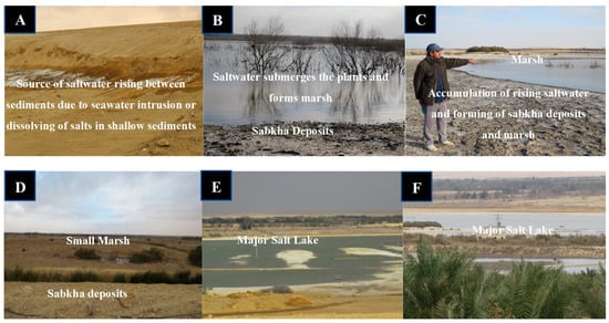
Figure 1.
Field photographs (A–F) represent the main surface phenomena due to the rise and accumulation of saltwater and salts on the surface of the sediments, and the formation of salt lakes, sabkhas, and marshes because of seawater intrusion.
2. Description of the Study Area
The study area is located northwest of the Sinai Peninsula near the Suez Canal, Egypt, specifically east of it, next to the Bitter Lakes. The area is located between latitudes 30°19′11″ and 30°22′50″ N, and longitudes 32°28′00″ and 32°33′20″ E (Figure 2). This area is characterized by a dry and semi-arid continental climate. The temperature ranges between 15 °C, in the winter, to 35 °C or to 40o C in the summer. Rainfall generally increases in the winter, except for the southern areas, where it falls. Rainfall occurs at distant annual intervals, and sometimes the rain reaches torrential rains, and its average rainfall ranges between 80–90 mm/year.
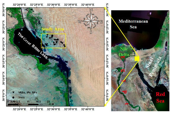
Figure 2.
A general map showing the location of the study area.
2.1. Topography and Geomorphology
This area is located in the flat area east of the Suez Canal, with a slight slope in the northeastern part. This slope is steep in the southwestern part with the presence of sand dunes that cover most of the area. These dunes exist in different types and sizes depending on both wind speed and direction, as well as it locates to the northeast of the area (Figure 3, left panel). Also, there are many mountains and valleys such as Wadi Al-Jedi, Wadi Al-Raha, Wadi Al-Tuwal, Wadi Jabal Al-Hamra, Jabal Al-Har, and others with altitudes ranging from 500–800 m + mean sea level (m.s.l.). Also, this area is characterized by the presence of waterways and distinct crops, and its surface is covered by groups of dense, spreading sand dunes. The ground level in most of the study area ranges between −5–40 m, (Figure 3, right panel). The topographical slope of the area is generally from the northeast, where the land level is ~115 m, to the southwest, where the level is −5 m, with a difference of 110 m in slope.
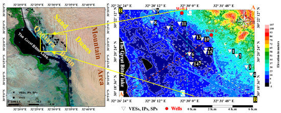
Figure 3.
A topographical contour map of the study area (right panel) showing the location of the geoelectric measurements, as well as the topographic profiles, and the basic geomorphological units along and around the study area (left panel).
Three topographical profiles were made, their directions SW-NE, NW-SE, and S-N, to illustrate the general slope direction in relation to the area (Figure 3, right panel). The previous elevation map and these topographic profiles (Figure 4) showed that the direction of the general slope is towards the central part, where the lowest elevation values are ~−5. It also contains one of the salt lakes, in the central part of the area, which is considered a lake for collecting water as a result of leaching from existing crops, as well as perhaps due to the rise in water resulting from seawater intrusion (photographs E and F in Figure 1). The topographic map (Figure 3, right panel) may be an interesting step for knowing the direction of the flow of excess seawater intrusion along the area.

Figure 4.
The topographic profiles (A-A), (B-B), and (C-C) and their directions along the study area as distributed in the topographic map (Figure 3, right panel) (Distance × 100 km and Elevation in m).
Regarding the geomorphology of the area, there are five distinct geomorphological units in and around the area (Figure 3, left panel), and they are as follows:
Mountainous areas: These are lands that are sharp, solid, and higher than their surroundings. They are located to the southeast and east of the Gulf of Suez and disappear from the area under study.
Salt lakes: Generally, the area is characterized by its proximity to the Suez Canal waterway, and the small lakes are one of the results of the area adjacent to this canal, which has sharp edges, where there are some folds or erosion in the wall of the canal, which helps in the formation of such lakes that were formed as a result of water operations. The few carvings and erosion in the semi-flat edges that do not have sharp sides may be the result of faults located between Qantara basin and sand dunes to the east of the area (Figure 1E,F).
Sand dunes: They are large gatherings of fine, loose sand in the upper parts and stable or fixed in the lower parts. These dunes were formed in the Holocene and Pleistocene ages and are characterized by different longitudinal or pillow-shaped shapes. This unit is considered water traps that depend on the period and duration of rainstorms.
Qantara basin: This basin extends to the far north of the area, specifically at Qantara east, and appears in the form of a strip parallel to the Suez Canal. It is characterized by an abundance of beach sand and a topography lower than sea level.
Sabkhas: They are lowlands covered with salts and clay, which are visible in many places, especially next to the lake towards the southwest of the area (Figure 1B,D).
2.2. Geological Setting
This area is characterized by the fact that its surface is almost flat, with some ripples created by the wind, and others are covered with calcareous deposits, non-calcareous aggregates, and valley sediments ranging in age from the Oligocene to the Quaternary age. In general, its geology and hydrogeology were described by several authors like [,,,].
The surface geology, as described from the geologic map of UNSECO Cairo Office [], consists of the Holocene and Pleistocene sediments of the Quaternary deposits. Holocene sediments include marshes, sand deposits (sand sheets), and sand dunes that cover large areas throughout most parts of the area. These sediments extend from the east of the lakes in the south passing through the area to the Qantara basin and then to the far northeast (Figure 5). As for the Pleistocene deposits, they consist of sand intercalated with clay (Qantara Formation) and deposits of a mixture of black and white sand with silt (the Sehle Al-Tina Plain Formation).

Figure 5.
Surface geologic map showing the surface geological formations in and around the study area (modified after UNSECO Cairo Office [], left panel, and the surface recorded sediments map from the interpretation of the geoelectrical methods.
In general, the thickness of the Quaternary deposits, which consist of previous formations in addition to ancient beach sand deposits and limestone with sandstone (Kurkar formation), is ~80–100 m. Ancient beach sand deposits consist of multi-grained sand with alternations of gravel and sandy clay layers. These deposits are located on top of limestone and sandstone deposits, which belong to Pleistocene deposits, and their thickness ranges from 20–60 m. As for the sand dune deposits, which cover the sand deposits that extend on the beach, they are often intercalation with sediments containing clay or gravel. There is also a layer of impermeable clay beneath it. Also, it represents a shallow aquifer with a thickness of ~20–30 m. All of these pre-Holocene and Pleistocene deposits reach a thickness of 100–130 m and may reach ~200 m and they are separated from the pre-Quaternary sediments by deposits of clay, shale, limestone, and sand (Figure 5, right panel). The photographs in Figure 6 represent the prevailing surface sediments along the area.
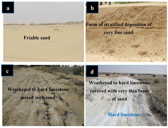
Figure 6.
A field photograph (a–d) showing the surface sediments along the study area.
The stratigraphic sequence of sedimentary rocks is represented by rock formations of different shapes and rock content belonging to multiple geological ages. Given the presence of groundwater mainly in sedimentary rocks, it will be exposed to the lithological characteristics of the most important formations. The present sedimentary deposits range from the youngest to the oldest, which explains the origin of the subsurface geology, as follows:
Holocene Quaternary sediments:
Sand deposits: include loose desert quartz sand deposits that range in size from fine to medium fine (Figure 6a,b). They appear highly concentrated in the north, and their disappearance in the rest of the area or their presence in very low concentration is due to their reclamation and cultivation.
Sabkha (salt) deposits: consist of sand, clay, organic materials, and calcium carbonate (Figure 1B–D). Most of them contain salt crystals in varying proportions.
Paleocene sediments: include valley sediments and fan sediments. The sediments of this age also include the Al-Tina Plain Formation and the Bir Al-Abd Formation.
Miocene-age sediments: which appear to be exposed in the area, are divided into two basic rock units, the lower part of which consists of sandstone, shale, and limestone, while its upper part consists of white limestone with intercalations of marl and chalky limestone (Figure 6c,d).
Oligocene deposits and Eocene Formation: consist of limestone, as shown in Figure 6d.
Pliocene sediments: include the Esna shale Formation.
Upper Cretaceous sediments: consist of limestone and some small intercalation of shale at the top (Figure 7, left and right panel), and include the Sidr Formation, the Matla Formation, the Watta Formation, and the Al-A’el Formation.
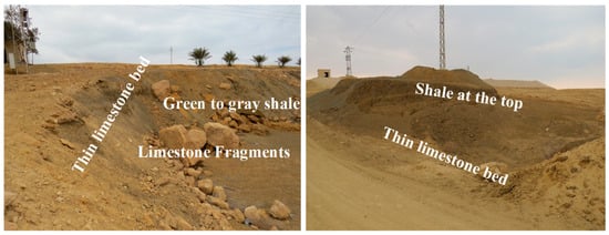
Figure 7.
A field photographs represent the limestone and shale, in the top, of the upper Cretaceous sediments.
Lower Cretaceous sediments: include the Raysan Unayzah Formation and the Maliha sandstone Formation.
Jurassic sediments: include the Raqbah Formation.
Triassic sediments: include the Qasib Formation.
2.3. Hydrogeological Setting
Several authors [,,] have studied the exploration and potentiality of groundwater in the northern and northeast parts of this area. Hydrogeologically, it contains groundwater that belongs to the Quaternary aquifer and it is considered a shallow aquifer in the upper layers, especially in the northwest of Sinai, where this area contains sediments of sand alternating with clay and silt. These sediments increase towards the west with some limestone layers. It is believed that this aquifer is not confined and may be confined in some areas, and water flows into it towards the northwest. It is characterized by salinity that increases towards the northwest, that is, towards the movement of water. This aquifer is mostly fed by surface water seeping into the sand layers, in addition to rainwater that penetrates into the upper range. The groundwater level in this aquifer is linked to the topography of the surface. The depth of water starts from 8–120 m towards the northwest of Sinai and the groundwater has low salinity, especially east and southeast of the area, and water salinity increases the closer we get to the course of the Suez Canal.
Generally, the aquifer was classified based on information from the hydrogeological map of the Fayed area []. It is either of the extensive or local type, with low productivity due to the presence of various contents of clay. Its average salinity is ~4500 ppm and it consists of sand and gravel with clay intercalated in different proportions. Also, from several previous studies, this aquifer was divided into two zones. The 1st zone is loose sand at the top of the sand dunes along the Suez Canal, with a thickness of ~20 m, a salinity of >10,000 ppm, and a water depth of ~1 m from the surface land depending on the topography of the area. The 2nd zone is medium sand, alternating with clay and silt, and groundwater that exists in the form of lenses with thicknesses ranging from 20–60 m and water depths from ~1 m in the lowland areas, −60 m, in the highland areas, and from the ground surface. Its water salinity of 500 ppm, to the east and southeast of the area, −4000 ppm or more, to the west and southwest, and also to the northwest. As for the Tertiary aquifer, it consists of fine to coarse sand with intercalates of silt, clay, and gravel in separate parts. Its thickness is >2000 m and the depth to water is ~500 m. It is characterized by high salinity of >20,000 ppm. There is also a sandstone aquifer belonging to the Lower Cretaceous period located in the south, in addition to the Jurassic aquifer.
3. Materials and Methods
The shallow geoelectric survey in this study includes Direct Current (DC) resistivity (VES) in Ωm and Direct Current Time-Domain Induced Polarization (DC-TDIP) in mV/V% methods. This survey aims to explore and determine the geological (lithological anisotropy) and hydrogeological conditions of surface and subsurface sediments, as well as their geometric dimensions in the horizontal and vertical directions. It will also be focused on identifying the type of saturated groundwater for the sedimentary facies. To conduct this study, fifteen (15) measurement stations were measured for each method, meaning that each station includes the two methods, or 15 measurement stations for each method, for a total of 30 stations, as distributed in Figure 2, Figure 3 and Figure 5. These measurements were made by staff of the Research Institute of Groundwater (RIGW) using the SYSCAL R2 device and the Schlumberger range application with a distance of 300 m to 700 m between the current electrodes (C1C2/2). The measured data from two methods include the apparent resistivity in Ωm and the chargeability in mV/V%. Figure 8 represents two examples about the measured data in form of curves in the freshwater area (station 1) and in the saline water area (station 6). For an array of current electrodes as the used Schlumberger array, C1 and C2, and potential electrodes, P1 and P2, the resistivity (Ωm) is calculated by the following Equation (1):
where ρa: the resistivity (Ω.m), I: the current intensity (A), and ΔV: the potential difference between the potential electrodes (V).

Figure 8.
Represents two examples of data measured in freshwater (station 1) and saltwater (station 6) areas.
3.1. Significance of Resistivity and Chargeability in Distinguishing Groundwater Types
Generally, to use the resistivity and chargeability for determining the depth to water and distinguishing between the zones of groundwater, the resulting calculated curves of the resistivity and chargeability were used as an initial model, based on [] (Figure 9, Figure 10 and Figure 11). Therefore, before achieving the goals of the study, it must first be determined whether there is an aquifer or not, then the depth to the aquifer or the depth to groundwater, and then the quality of groundwater and its zones, all of this in addition to determining the geological sediments that will be deduced later.
Generally, the comparison between the calculated curves of resistivity and chargeability revealed a variation in the depth of water presence, as shown at each measuring station in Figure 9, Figure 10 and Figure 11. Also, this comparison showed the presence of the fresh groundwater zone in measuring stations 1, 2, 3, and 4 (Figure 9), but in measuring stations 5, 6, 11, 13, and 15 (Figure 10), the saline water zone is present, while the mixture between the fresh and saline water zone is present in measuring stations 7, 8, 9, 10, 12, and 14 (Figure 11). Therefore, it can be concluded that the simultaneous increase in resistivity and chargeability indicates the fresh groundwater zone, as in stations 1, 2, 3, and 4 (Figure 9), but only the decrease in resistivity indicates the salt groundwater zone, as in stations 5, 6, 11, 13, and 15 (Figure 10). The previous two cases can also be detected in the same area when there is a fresh groundwater area above the salt groundwater area, such as in stations 7, 8, 9, 10, 12, and 14 (Figure 11).
Accordingly, it was noted that most of the groundwater locations along the area in the shallow and deep depths are salty water. All of these conclusions provide evidence that there is a large part of this area affected by the intrusion of seawater, but for a certain distance from the source of seawater, which is the Great Bitter Lake. There is also a shallow zone with fresh groundwater above the salt zone in some locations, and this may indicate that irrigation water has seeped down to a certain depth.
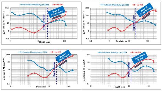
Figure 9.
Determining the depth of groundwater and identifying zones of fresh groundwater from the comparison between the calculated resistivity curves and the calculated chargeability curves along the study area.

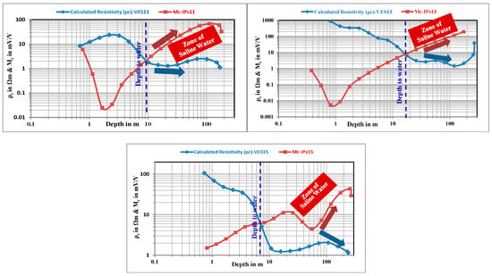
Figure 10.
Determining the depth to groundwater and identifying zones of saline groundwater from the comparison between the calculated resistivity curves and the calculated chargeability curves along the study area.
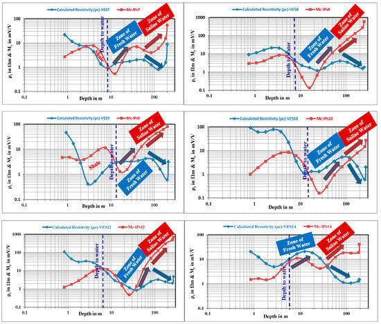
Figure 11.
Determining the depth of groundwater and identifying zones of mixed groundwater from the comparison between the calculated resistivity curves and the calculated chargeability curves along the study area.
3.2. Interpreting and Modeling of Resistivity Values
In general, quantitative interpretation of the measured apparent resistivity of the 15 VES, was performed using the Rinvert software version 2.1 [] to obtain the inverse model for determining two important parameters, namely the true resistivity and thickness of the subsurface geological layers. This model was calibrated with two productive wells (well-1 and well-2) and the lithological data of the two wells. Also, the lithological description of the recorded deposits with depth in the two wells was plotted and the geophysical outputs at each measured station were calibrated with the two wells, as shown in Figure 12, Figure 13, Figure 14, Figure 15, Figure 16, Figure 17, Figure 18, Figure 19, Figure 20, Figure 21, Figure 22, Figure 23 and Figure 24. These parameters, especially the true resistivity, will be interesting in determining the geological and hydrogeological settings of the shallow section. These settings include types of sediments, environmental depositional facies, and determining the hydrogeological properties of water-bearing layers with depth. In this study, through the variation of the resistivity values of subsurface sediments, it was easy to distinguish between dry, moisture, and saturated layers, and the change in water quality for the saturated layers, as well as the effect of groundwater type, vertically and horizontally, on the resistivity/conductivity of surface and subsurface sediments.
2D Resistivity Model and 2D Hydro-Lithological Model
According to the variation in the resistivity values, this area was classified into freshwater to brackish water zone, to the east, and saline water zone, to the west. It will describe the geological sequences and their hydrogeological implications in the two parts. In the first part, it has been divided the subsurface layers geoelectrically into seven electrical units that differ in their true resistivity and also their thicknesses. The details of the electrical properties of these units, as shown in the 3D fence diagram (Figure 12, left panel), and the deduced lithological sequences and their hydrogeological implications, as shown in the 3D fence diagram (Figure 12, right panel) and in the two 2D hydro-lithological cross sections (Figure 13) were predicting using the Rockworks software 16 [], as follows:

Figure 12.
A 3D fence diagram represents the change in the resistivity values (left panel) and the lithological sequence deduced from the interpretation of the true resistivity of measuring stations (right panel) along the study area.
The 1st geoelectrical layer is a surface layer of sand, silt with rock fragments. Its resistivity values range from 247 to 260 Ωm and its thickness ranges from 1 to 1.5 m. The 2nd layer is expected to consist of sand deposits with a little silt and clay. It is characterized by resistivity values ranging from 50 to 100 Ωm and a thickness ranging from 0.5 to 4 m. The 3rd layer is moisture sand. This was inferred from its resistivity values, which range from 23 to 143 Ωm. Its thickness ranges from 2 to 14 m. The 4th layer is expected to consist mostly of clay to sandy clay and characterized by a resistivity ranging between 1.5 and 9.5 Ωm and with a thickness ranging between 15 and 21 m. The 5th layer is expected to consist of sand with a minor clay in the presence of low saline water, whose resistivity ranges from 27 to 41 Ωm, and its thickness ranges from 39 to 51 m. The 6th layer consists of saturated clayey sand containing brackish water, whose resistivity ranges from 10 to 17 Ωm, and its thickness ranges between 28 and 36 m. While the 7th layer consists of clay, whose resistivity ranges between 3 and 7 Ωm and it is expected to start at a depth of 101 to 112 m and considered the base of the upper Quaternary aquifer represented by the 5th and 6th layers.
In the second part, it has been divided the subsurface layers geoelectrically into eight electrical units. The details of the electrical properties of these units and the inferred lithological sequences and their hydrogeological implications (Figure 12, left panel and right panel) and (Figure 13) are as follows:

Figure 13.
Two 2D hydro-lithological cross sections (S-N-NE-SW-SE-NW direction, left panel, and SE-NW direction, right panel) to represent the distribution and change in the hydro-lithostratigraphic units, as well as fresh and saline groundwater zones along the study area.
The 1st layer is a very thin surface layer of sand and silt with a few limestone rock fragments and is transformed into hard to weakly hardened limestone in many locations. It is characterized by a resistivity ranging from 590 Ωm, in the presence of hard and soft limestone, to 6 Ωm, in the presence of silt and sand with minor rock fragments of limestone. Its thickness is ~ 0.5 to 1.5 m. The 2nd layer consists of sand deposits with silt and clay and will turn into limestone in some locations (Sand with minor clay content and silt to soft limestone) and is characterized by a resistivity range from 43 Ωm in the presence of limestone, to 0.5 Ωm when clay and silt increase with sand in the occurrence of saltwater. Its thickness ranges between 2 m and 6 m. The 3rd layer consists of sandy clay and turns into sandy clay to soft limestone in some locations. Its resistivity ranges between 34.5 Ωm, when limestone is present, and 0.5 Ωm, when clay and silt are present, with salt water. The thickness ranges between 1.5 and 17 m. It is clear from the three aforementioned layers that most of the second part of the area is covered by a very thin layer of sand, silt, sometimes clay, and then limestone. The 4th layer is composed of clay or shale and is characterized by a resistivity ranging between 0.3 and 4 Ωm. It is saturated with saltwater and is located under the limestone layer with a thickness ranging between 7 and 24 m. The 5th layer consists of saturated sand with a minor content of shale with saline water. Its resistivity ranges from 0.7 Ωm, with increasing groundwater salinity, to 11 Ωm, and its thickness ranges from 12.5 to 50 m. The 6th layer consists of saturated clayey sand to sandy clay with saline water, containing salty water, and its resistivity ranges from 0.2 Ωm, when the clay content and water salinity increase, to 6 Ωm. Its thickness ranges from 35 m to 71 m. The 7th layer consists of clay (0.2 to 3 Ωm) then it turns into shale with thin beds of sand (6 to 8 Ωm), which is considered the base of the upper Quaternary aquifer, and its thickness ranges from 54 to 140 m. The 8th layer consists of sandy limestone with shale intercalations (12 to 47 Ωm). This layer is expected to start at a depth of 152–246 m or a little more in some locations.
A large fault is inferred between the freshwater and saltwater zones (Figure 12, right panel, and Figure 13). It will be considered the main reason for separating the two groundwater zones and also to prevent the invasion of seawater into this part of the area. Therefore, the northeastern part does not contain marshes, lakes, or sabkhas because its sediments are characterized by a high infiltration rate, and the present shallow shale layer is small in thickness and not extended, as in the second part, in addition to the absence of an influx or rising of saltwater to the surface. The direction of this fault is northwest-southeast, i.e., parallel to the Gulf of Suez. Its up-throw is towards the sand dunes and mountain area, while its down-throw is towards the Qantara basin and the Great Bitter Lake. Accordingly, it is believed that it may extend long distances beyond the area and parallel to the Gulf of Suez. It may also be the reason for the creation of the Qantara Basin and some lakes, as well as the appearance of marshes and sabkhas and the deterioration of large areas of surface sedimentary formations as a result of the upward flow of water.
4. 3D Hydro-Lithological Model
This model is designed to represent the recorded lithology from bottom to top in a 3D visualization based on the interpreted resistivity values to understand the distribution of saturated and dry sediments, as well as appearing of marshes, sabkha deposits, and lakes. Emphasis was placed on the distribution of clay, clayey sand, and sand saturated with freshwater and saltwater, extension, and contact between saltwater and freshwater sediments. This model also shows the surface sediments affected by downward and upward water seepage and deduces their causes and direction and the main cause of seawater seepage and infiltration.
Based on previous geoelectrical interpretations in addition to geological and hydrogeological data, the general and expected sedimentary formation in the 1st part of the area is sand, silt, and clay deposits with sand, sand, and clay to sandy clay and sand, then clay sand and then clay. The recorded aquifer is characterized by fresh to saline water and is expected to be good to medium and poorly productive. This productivity depends on the increase and decrease of clay/shale content, as well as the recharge of this aquifer depends on quantities of rainwater and floods. The thickness of this aquifer ranges from 70–87 m and the depth to groundwater starts from 24 to 35 m (average of ~30 m).
The general and expected sedimentary formation in the 2nd part is deposits of sand and silt with clay, limestone, shale, and sand, then clayey sand to sandy clay, then shale with thin layers of sand, then sandy limestone. It is quite clear that there is a similarity between the layers recorded in this part with the layers recorded in the 1st part, with some differences. These differences represent in the appearance of limestone and shale in the surface layers in the 2nd part, which are expected to appear towards the northwest of the 1st part, that is, the northern eastern side of part two. The aquifer is characterized by containing salty water, the salinity increases towards the lake and the Suez Canal, in quantities that are expected to be good to moderate and low due to the increase in clay layers in this direction as well as its content within the aquifer. Its thickness ranges from 48–122 m. This indicates that this part was affected by the presence of a major fault, especially along the Great Bitter Lake, that is, from the southeast to the northwest (Figure 14 and Figure 15, right panels). The depth to water starts from the surface, especially inside the lake located in the center of this part, and from 17–33 m within the layers of the main aquifer, with an average of ~25 m.

Figure 14.
A 3D diagram to show the distribution of VESs and wells with lithology (left panel) and A 3D hydro-lithological model to represent the geological layers and their hydrogeological evidence (right panel) along the study area.
The low resistivity values of the surface layer in some locations, especially in the central, south, west, southwestern, and northwestern parts, reflect the accumulation of irrigation water in it over time and then its upwards through the sediments as a result of the presence of the shale layer beneath it. As it upwards, it carries dissolved salts with it to the top, causing the layer to become saturated with saline water and the salts to appear on the surface (Figure 1, panel A), and marshes are formed and then sabkha deposits are formed (Figure 1, panels B–D). Field investigations found veins of evaporites accompanying the shale layer (Figure 7, panel O), which indicates that they are the source of the salts and the reason for the appearance of such phenomena, in addition to the rising of water from the bottom in some locations.
Through the 3D hydro-lithological models in Figure 15 (left panel), it was possible to show the distribution of the clay/shale layer, its depths, and distribution because it is one of the layers characterized by very low hydraulic conductivity. So, it often causes major hydrogeological and environmental problems, if any. This model explained the locations of most exposed sites and shallow sediments to the buildup of salts and saltwater, as well as the depths and main direction through which seawater intrusion occurs and the area of most exposed to create marshes and salt lakes. The right panel in Figure 15 shows that the 1st part is a separate part from the 2nd part. This is likely due to the presence of a fault between both and that the 1st part is located towards its upthrow, which made this shallow part less susceptible to horizontal seawater intrusion as a result of the presence of the shale layer. This layer corresponds to the depths of the main direction through which seawater seepage occurs.

Figure 15.
A 3D hydro-lithological model to show the distribution of pure clay/shale (left panel) and distribution of clay/shale and saturated clayey sand and sand with freshwater, as well as shallow dry sediments (right panel) along the study area.
Also, through the 3D hydro-lithological model in Figure 15 (left panel), the saturated layers have been clarified from top to bottom, in addition, it has been clarified that the 1st part is affected by the seawater intrusion. This effect was at deep depths and beneath the shale layer. As for the 3D model in Figure 16 (right panel), it explained the areas unaffected by saltwater intrusion, under the 1st part, due to the presence of clay/shale layer in the base and inferred the fault.

Figure 16.
A 3D hydro-lithological diagram to show the distribution of saturated sand, sandy clay with saline water, wetted sand, and clay with saline water (sabkha deposits), as well as moisture sand and gravel (left panel) and distribution of clay, sediments saturated with saline water and limestone and gypsum covered with thin sand bed (right panel) along the study area.
4.1. 2D Chargeability Model
Generally, the induced polarization method has been used to measure the chargeability of subsurface geological materials, which is an induced polarization potential resulting from the interruption of electrical current during a collision with them. The rock characteristics of the geological layers, the types of pores and their geometry, as well as the percentage of saturation or the amount of water entering the pores, are among the most influential factors on the rate of decay of this potential. Therefore, this property is more influential in distinguishing between subsurface materials and layers. In addition, high chargeability values were recorded in clay and/or shale layers while in sandy or pure layers (non-clayey layers), the recorded chargeability values were moderate to low []. This means that chargeability is high in saturated clay deposits with low in resistivity []. Vanhala et al. and Weller et al. [,] found that chargeability values can give more detailed information about rocks in geological layers than resistivity values, which are affected by several factors such as clay content and salinity.
Vacquier et al. [] reported that the chargeability values of sand and clay mixtures were proportional to the constituent of clay. Keller and Frischknecht [] reported that there are high polarization values for different clays and their concentrations. Parkhomenko [] found that higher or lower clay contents will give higher or lower chargeability and chargeability increases with increasing water content until optimum saturation is reached beyond which IP decreases. Also, [] indicated that the largest IP effects are obtained for clay contents in the range of 3–10% (clayey sediments). Ogilvy and Kuzmina [] observed that a maximum chargeability response occurs for optimum water content in clayey sands. Increasing the electrical conductivity of the electrolyte and its salinity (ion concentration) reduces the IP effect [].
Draskovits and Smith [] observed that dry coarse sands and gravels are characterized by low chargeability value and high resistivity value as in the recorded shallow dry deposits along the area. Maximum polarizability/chargeability was associated with silty layers with medium resistivity while clay deposits with low resistivity values and high polarizability/chargeability were also detected along the area. Therefore, the IP method will be effective and useful in predicting clay content in host sediments and aquifers. Barker [] reported that chargeability would increase with increasing groundwater salinity up to 500 mg/l. Kiberu [] reported that IP/chargeability depends on water and clay content and its response is possible when the sediments contain little water rather than being completely dry and it can be said that IP/chargeability is highly dependent on the water amount. Leroux et al. [] reported that high chargeability values appeared in saturated or nearly saturated sediments and that the salinity and composition of the electrolyte have an influence on the way this high value occurs.
In this study, the measured chargeability is the raw chargeability (Mr) and it considered as normalized (Mn) because the used period was 2000 ms and expressed as shown in the following Formula (2) []:
where VDC: potential (V) used to calculate direct current resistivity, Vip: The intrinsic or secondary potential (mV), and ti and ti+1: The open and close times (s) for the gate over which signal is integrated.
4.2. Chargeability Interpretation
Generally, interpreting the chargeability of layers is complicated by small-scale sediment heterogeneity. Moreover, the mineral and chemical composition, environment and soil texture show the difficulty of polarization mechanisms [,,]. Sediments with high clay content have high chargeability values and hard formations may have high chargeability when they include a high shale/clay content. Soils with uniform particle size such as sand and gravel produce lower chargeability []. The variation of Mn determines the permeable sediments that represent the aquifer or contain groundwater or water-conducting sediments from clay deposits.
Therefore, the calculated chargeability values for each Time-Domain Induced Polarization (TDIP) sounding (TDIPs) with depth were used to separate shale/clay deposits from non-shaly/clayey sediments. In general, this separation helps in understanding the geological sedimentation system, the hydrogeological situation, the interaction between the different water-bearing layers of different sediments and salinity, and the groundwater quality compared to the resistivity. All of these conclusions will help in predicting the reasons for the rising of saltwater, and also explaining why salts accumulated in other places and not others? which over time helped in the appearing of salt deposits.
Based on the 3D fence diagram and 2D cross-section (Figure 17), which represent the change in the chargeability values of the recorded sediments, it can conclude the sediment types and their implications. Where there are sand and gravel, limestone with shale, sand, saturated sand, saturated clayey sand, and then clay and sandy limestone have been recorded along the area. Water-bearing layers are characterized by containing fresh to brackish water in the 1st part while these layers containing saltwater, the salinity increases towards the lake and the Suez Canal. Also, it can clear that there is a similarity between these layers recorded along the area with some differences in appearing of limestone and shale in the shallow layer in the 2nd part.
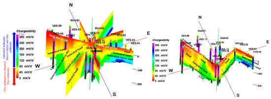
Figure 17.
A 3D fence diagram (left panel) and a 2D cross section-oriented S-N-NE-SW-SE-NW (right panel) to show the change in the chargeability values of the recorded sediments along the study area.
5. Results and Discussions
5.1. 3D Resistivity Model
This model was built using the true resistivity values deduced from interpreting the apparent values of resistivity, passing through the forward model and then the inverse model, as mentioned before using the Rinvert software version 2.1 []. These values are useful in distinguishing horizontally and vertically among the hydro-lithostratigraphic units, which includes separating dry and saturated sediments and their groundwater implications and quality, as well as separating the shaly and non-shaly layers. These values are also useful in separating the groundwater zones based on the decrease in resistivity values. The separation of shale from non-shale layers reflects and explains the distribution of highly permeable layers (non-shale layers such as sand and gravel), medium permeability (layers (clayey/shaly sand and sandy clay/shale), and very low permeability (shale layers) along the area. Monitoring and distributing the layers, horizontally and vertically, based on their permeability is useful in determining the locations and depths at which groundwater flows. Accordingly, the creation of marshes, as well as sabkhas and the sabkhas deposits are expected. Based on all of the above, and to demonstrate, clarify, and understand these results, a 3D resistivity model was built, as shown in Figure 18, Figure 19, Figure 20, Figure 21 and Figure 22.
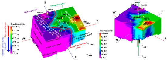
Figure 18.
A 3D resistivity model from N-S (left panel) and from W-E (right panel) to show the distribution of very low to high resistivity values of the recorded sediments, as well as high-impact areas due to saltwater intrusion, seepage water, and unimpacted areas along the study area.
The 3D resistivity model (Figure 19) represents the very low to high resistivity values of the sediments recorded along the area. Very low resistivity values reflect clay while high values reflect dry pure sediments. The clay layer refers to impermeable zones that are either dry or saturated, as recorded at the shallow and deep depths. Dry surface sediments consist of dry sand and gravel and also limestone with gypsum. According to the distribution of resistivity values, it was classified into unimpacted sites located to the east, southeast, and northeast, and high-impact sites located to the west, southwest, and northwest. Also, these values indicated a large fault that led to a separation between the impacted and unimpacted sites (Figure 12, Figure 13, Figure 14, Figure 15 and Figure 16). Unimpacted sites include the dry shallow Quaternary sediments, saturated sand sediments with freshwater, sandy clay to clayey sand with fresh to brackish water, and then clay deposits. While high-impact sites include surface sediments affected by the rising of saltwater and zones of water seepage, which led to water accumulation at shallow depths. This will assist in appearing the marshes and rising of saline water to the upper sediments. High-impact sites also include a thin surface clay layer, clayey saltwater areas, then a thick clay layer at the base, and sometimes sandy limestone.
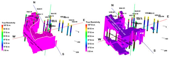
Figure 19.
A 3D resistivity model for the resistivity values from 2–10 Ωm (left panel) and from 10–20 Ωm (right panel) along the study area.
A 3D resistivity model was built to distribute the resistivity values ranging from 2–10 Ωm, and it referred to the depths and zones of clay to sandy clay and saline water intrusion (Figure 19, left panel). The values range from 10–20 Ωm referred to the depths and zones of sandy clay to clayey sand and saline water (Figure 19, right panel). The previous zones and depths were recorded to the west, northwest, and southwest. The last values reflected that the clay and sandy clay to clayey sand were affected by seawater intrusion. Likewise, a 3D resistivity model was built for resistivity values ranging from 10–40 Ωm (Figure 20, left panel) to define the boundaries between saltwater, freshwater, and brackish water, as well as the depths of clayey sand and zones of brackish water to freshwater. Also, these values showed the locations, extent, and limits of the presence of sandy clay to clayey sand sediments. This model showed that the central parts include saturated clayey sand, which is characterized by moderate permeability, which helps the rising of saltwater and increases water flow through it. The range of resistivities from 15–50 Ωm (Figure 20, right panel) showed depths and zones of clayey sand to sand saturated with fresh and brackish water, and they extend from the center of the area to the east. In general, clayey sediments were detected and distributed, leading to the identification of permeable sediments.
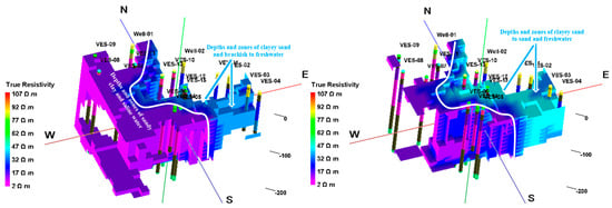
Figure 20.
A 3D resistivity model for the resistivity values from 10–40 Ωm (left panel) and from 15–50 Ωm (right panel) along the study area.
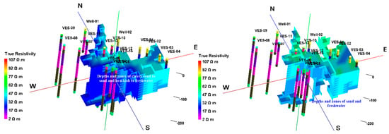
Figure 21.
A 3D resistivity model for the resistivity values from 20–50 Ωm (left panel) and from 30–60 Ωm (right panel) along the study area.
This is also the case in the 3D resistivity model for resistivity values of 20–50 Ωm (Figure 21, left panel), which specifically shows the depths and zones of clayey sand to sand with minor clay content saturated with freshwater and brackish water, which extends from the center of the area to east. In general, these values indicate that the central parts are characterized by the presence of high to moderate permeability sediments, which makes them more susceptible to the rising of water accompanied by salts, in addition to the accumulation of these salts forming slat deposits (images from B–F in Figure 1)). While resistivity values of 30–60 Ωm (Figure 21, right panel) indicate the depths and zones of sand saturated with freshwater. It is clearly seen from the center (less abundant) to the east (more abundant). All the previous evidence indicates that the depositional environment along the area is largely similar, but due to the occurrence of the fault, led to the subsidence and separation of the western part of it, which was exposed to the phenomenon of saltwater intrusion and the appearance of lakes and marshes (Figure 1), especially in very low-lying sites (Figure 3, right panel). The fault zone may be the zone that helped in the rising of water. So, this led to an increase in the groundwater pressure in the low parts causing rising water through sediments of high and medium permeability. Over time, this led to the appearance of lakes and marshes.
5.2. 3D Chargeability Model
3D Visualizing Model of Chargeability and Its Lithological Signification
Generally, the interpretation of chargeability values was done using its calculated values, as mentioned in the curves in Figure 9, Figure 10 and Figure 11 by inversion of the raw data using iterative algorithms similar to resistivity. Accordingly, the 3D model of chargeability is designed to represent the change in chargeability values depending on the sediment types and their water content. The variation of these values depends on water content and clay content []. An induced polarization response is also possible when the sediment contains a small amount of water rather than being completely dry and is generally highly dependent on the amount of water. Accordingly, the environmental deposition of the recorded sediments can be understood. Therefore, the dry surface sediments and clay/shale recorded low chargeability values while saturated bore deposits, saturated clay sediments, and saturated clay or shale recorded medium to high values (Figure 22). Cohen [] stated that the interactions between clay minerals and groundwater can produce an increase in chargeability and reduce the resistivity values. So, according to [], the chargeability will be high and the resistivity will be low, especially in the saturated clayey sediments (Figure 22, left panel). Also, it can be said that the induced polarization method can be used to predict the clay content in the host sediments and groundwater aquifer depending on the low and high values of chargeability.
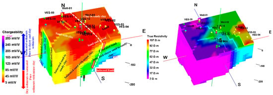
Figure 22.
A 3D chargeability model for representing the chargeability values of the recorded sediments (left panel) compared to a 3D resistivity model (right panel) along the study area.
Therefore, chargeability is low in compact shales as in the shallow shales or which cover the limestone (Figure 7) and it is high in saturated clays as in the deep clay layer. According to Draskovits and Smith (1990), it is observed that dry coarse sand and gravel are characterized by high resistivity and low chargeability values such as in the case of the surface and shallow dry sediments (Figure 22). According to Leroux et al. (2010), high chargeability values were recorded in the saturated sediments and the high salinity of groundwater have an influence upon the occurrence of high chargeability values (Figure 22, left panel). Therefore, the chargeability increases with increasing the concentration of clay (Figure 22, left panel) and when the pores are saturated with fresh water, as shown in the southeastern area. Also, it varies with varying the amount of water in the pores meaning that the saturated sediments have medium to high chargeability while the dry sediments have low chargeability (Figure 22).
Figure 23 and Figure 24 display the ranges of the calculated chargeability values for the recorded sediments. These values indicate that the sediments are clayey or mixed with clay, and also whether these sediments are dry or saturated with water, as well as their water quality. Previously, these values were used in comparison with the calculated resistivity values to determine the depth of groundwater or the aquifer and to determine water quality (Figure 9, Figure 10 and Figure 11). Next, the depositional setting was visualized and described, and the increase in clay content was determined vertically and horizontally along the area. This setting helps in predicting the hydraulic conductivity qualitatively and its trend and then determining the locations and depths at which the rate of seepage and rising of water increase.
Chargeability values of 5–50 mV/V (Figure 23, left panel) indicate dry surface deposits consisting of sand and gravel, limestone covered with sand, sand with a minor clay, and dry clay. The values from 50–100 mV/V (Figure 23, right panel) indicate clayey sand-to-sand deposits with saline water towards the west and sand with freshwater deposits towards the east. The first deposits are located in the downthrow of fault, that is, towards the low part of the area, and these deposits increase chargeability values, which indicates an increase in clay content, water salinity, and also hydraulic conductivity. Other sediments are located towards the high part of the area, and they have low chargeability values, which indicates a decrease in clay content, water salinity, and an increase in hydraulic conductivity. This reflects that these sediments have similar depositional facies along the area, but due to the occurrence of the fault, the western part subsided, making it exposed to the intrusion of seawater, which led to high chargeability values, as well as the accumulation of salty water in the central parts due to the low hydraulic conductivity value. The high hydraulic conductivity of the sediments caused water to rise, creating salt deposits.

Figure 23.
A 3D chargeability model for the chargeability values from 5 to 50 mV/V (left panel) and from 50 to 100 mV/V (right panel) along the area of study.
Chargeability values of 100–200 mV/V (Figure 24, left panel) indicate a sandy clay to clay containing saline water sediments, i.e., an increase in clay content with accompanying sand and saltwater and the appearance of clay layers. These deposits are found in the deep part to the west, in the central part, and the northwest, while they are found in the shallow part to the east and consist of sand clay with brackish water and clay below it. All of these deposits represent the base of the explored sedimentary section in the area. It has a high clay content and high salinity and is expected to have low hydraulic conductivity.
Finally, chargeability values ranging from 50–290 mV/V (Figure 24, right panel), which generally concentrate and reflect the previously mentioned saturated sediments and their vertical and horizontal distribution, as well as the depths at which they can increase in clay content and the depths at which the clay layer appears. So, it can be concluded that there is a depositional basin in the center of the area, especially in the lower part of the fault. This basin is characterized by depth by the presence of sand with a little clay content, then sand with a high clay content, then clay. This means that hydraulic conductivity increases from the top, where the sand sediments increase, and decreases to the bottom, where the clay content increases. It is also expected that the hydraulic conductivity will increase sideways towards the Great Bitter Lake, which helped these sediments to be invaded by seawater and then rise to the top, especially in the center of the area, which is free in clay. This led to the appearance of the lake and some small, shallow marshes. In other sites where shallow clay layers, sabkhas are formed, and water rises through them to the top.

Figure 24.
A 3D chargeability model for the chargeability values from 100 to 200 mV/V (left panel) and from 50 to 290 mV/V (right panel) along the area of study.
6. Conclusions
Determining and identifying the physical properties of the dry and saturated subsurface layers in complex sedimentary facies requires several integrated geological, hydrogeological, and geophysical studies. These properties include the types of sediments, their horizontal and vertical extension, their depositional environment, and their structural conditions, the separating of permeable and impermeable sediments, dry and water-saturated sediments, and their groundwater quality. Therefore, to identify the previous properties, surface geophysical measurements were carried out using resistivity and induced polarization methods in addition to geological and hydrogeological data.
Accordingly, by comparing the calculated resistivity and chargeability values, it was possible to determine the depth of water and divide the groundwater zones with depth. Based on the interpretation and analysis of resistivity values, a 2D and 3D resistivity modeling of sediments was done. Also, a 2D and 3D hydro-lithological model was designed to determine the types, extension, water content, and composition of sediments, as well as their water quality. Because there is ambiguity in the results of the resistivity method as a result of the saturation of saltwater, the presence of shale layers, the accumulation of salts in the surface layers, and the sabkhas formation, the IP method was applied to reduce this ambiguity. By applying this method, the chargeability values of the sedimentary section were measured, and then 2D and 3D chargeability modeling was done to accurately separate and identify the sediments and their hydrogeological conditions. The interesting outputs of this method were the distinction and separation between clayey and non-clay layers, and layers containing saltwater. Finally, by integrating these two methods, the various geological and hydrogeological characteristics of the sedimentary section were identified and understood. Also, based on the applied methodology and its deduced outcomes, it can be recommended for its application to understand and identify sediments and their facies, dry and saturated sediments, and their hydrogeological characteristics, as well as determine the type of groundwater in areas with very complex sedimentary facies that are expected to be invaded by seawater.
Author Contributions
Conceptualization, A.M. and A.I.A.; methodology, A.I.A.; software, A.I.A.; validation, A.I.A. and A.M.; data curation, T.O.A. and A.M.; writing—original draft preparation, A.I.A.; writing—review and editing, A.M. and M.G.; visualization, A.K.S. and M.E.A.-E.; project administration, A.M. and A.K.S. funding acquisition A.M. All authors have read and agreed to the published version of the manuscript.
Funding
This work was funded by the Deanship of Scientific Research at Jouf University under Grant Number (DSR2022-RG-0107).
Data Availability Statement
Unpublished data and results of analyses presented herein are available upon request from the corresponding author.
Conflicts of Interest
The authors declare no conflicts of interest.
References
- Mazac, O.; Kelly, W.E.; Landa, I. A hydrogeophysical model for relation between electrical and hydraulic properties of aquifers. J. Hydrol. 1985, 79, 1–19. [Google Scholar] [CrossRef]
- Mazac, O.; Cislerova, M.; Kelly, W.E.; Landa, I.; Venhodova, D. Determination of hydraulic conductivities by surface geoelectrical methods. In Geotechnical and Environmental Geophysics; Ward, S.H., Ed.; SEG: Tulsa, OK, USA, 1990; Volume II, pp. 125–131. [Google Scholar] [CrossRef]
- Purvance, D.T.; Andricevic, R. Geoelectric characterization of the hydraulic conductivity field and its spatial structure at variable scales. Water Resour. Res. 2000, 36, 2915–2924. [Google Scholar] [CrossRef]
- Purvance, D.T.; Andricevic, R. On the electrical–hydraulic conductivity correlation in aquifers. Water Resour. Res. 2000, 36, 2905–2913. [Google Scholar] [CrossRef]
- Rubin, Y.; Hubbard, S.S. Hydrogeophysics: Water Science and Technology Library; Springer: Dordrecht, The Netherlands, 2005. [Google Scholar] [CrossRef]
- Parks, E.M.; McBride, J.H.; Nelson, S.T.; Tingey, D.G.; Mayo, A.L.; Guthrie, W.S.; Hoopes, J.C. Comparing electromagnetic and seismic geophysical methods: Estimating the depth to water in geologically simple and complex arid environments. Eng. Geol. 2011, 117, 62–77. [Google Scholar] [CrossRef]
- Slater, L.D.; Lesmes, D. IP interpretation in environmental investigations. Geophysics 2002, 67, 77–88. [Google Scholar] [CrossRef]
- Vanhala, H.; Soininen, H.; Kukkonen, I. Detecting organic chemical contaminants by spectral-induced polarization method in glacial till environment. Geophysics 1992, 57, 1014–1017. [Google Scholar] [CrossRef]
- Weller, A.; Frangos, W.; Seichter, M. Three-dimensional inversion of induced polarization data from simulated waste. J. Appl. Geophys. 1999, 41, 31–47. [Google Scholar] [CrossRef]
- Ammar, A.I.; Gomaa, M.; Kamal, K.A. Applying of SP, DC-Resistivity, DC-TDIP and TDEM soundings in high saline coastal aquifer. Heliyon 2021, 7, e07617. [Google Scholar] [CrossRef] [PubMed]
- Ammar, A.I.; Kamal, K.A.; El-Boghdady, M.F.M.; Ibrahim, O. 2D and 3D visualization of aquifer sediments, surface water seepage and groundwater flow using DC-resistivity, DC-IP, and SP methods, West El-Minia, Egypt. Environ. Earth Sci. 2023, 82, 21. [Google Scholar] [CrossRef]
- Said, R. The Geology of Egypt; Elsevier: Amsterdam, The Netherlands, 1962. [Google Scholar]
- Moustafa, A.R.; Khalil, M.H. Structural Characteristics and Tectonic Evolution of North Sinai Fold Belts, Geology of Selected Areas. In The Geology of Egypt, 1st ed.; Said, R., Ed.; Routledge: London, UK, 1989. [Google Scholar]
- Abdallah, G. The Groundwater Conditions in the Area from Rommana to Bir ElAbd, Especially the Area South of Rabea Village, North Western Sinai Peninsula, ARE. Master’s Thesis, Cairo University, Giza, Egypt, 1992. [Google Scholar]
- JICA. North Sinai Groundwater Resources Study in the Arab Republic of Egypt; Final Report; JICA: Tokyo, Japan, 1992. [Google Scholar]
- UNSECO Cairo Office. Geologic Map of Sinai, Egypt, Scale 1:500,000, Project for the Capacity Building of the Egyptian Geological Survey and Mining Authority and the National Authority for Remote Sensing and Space Science in Cooperationwith UNDP and UNSECO; Geological Survey of Egypt: Cairo, Egypt, 2005. [Google Scholar]
- Ibrahim, E.H.; Shereef, M.R.; El Galladi, A.A.; Pederson, L.B. Geoelectric study on Quaternary groundwater aquifer in northwestern Sinai, Egypt. EGS J. 2004, 2, 69–74. [Google Scholar]
- Santos, F.M.; Sultan, S.A.; Patrıcia, R.; El Sorady, A.L. Joint inversion of gravity and geoelectrical data for groundwater and structural investigation: Application to the northwestern part of Sinai, Egypt. Geophys. J. Int. 2006, 165, 705–718. [Google Scholar] [CrossRef]
- Sultan, S.A.; Mekhemer, H.M.; Santos, F.M. Groundwater exploration and evaluation by using geophysical interpretation (case study: Al Qantara East, North Western Sinai, Egypt). Arab. J. Geosci. 2009, 2, 199–211. [Google Scholar] [CrossRef]
- Research Institute for Groundwater (RIGW). Hydrogeological Map of Egypt, Scale 1:500,000, 1st ed.; RIGW, NWRC: Nile Delta, Egypt, 1992. [Google Scholar]
- Zohdy, A.R.; Bisdorf, R.J. Programs for the Automatic Processing and Interpretation of Schlumberger Sounding Curves in Quick BASIC 4.0; United States Department of the Interior, Geological Survey: Reston, VA, USA, 1989. [Google Scholar] [CrossRef]
- Rinvert Software, version 2.1; Geophysical Software Package: Licensed to Hydrogeology and Engineering Geology; Geophysical Software: Hochi Minh City, Vietnam, 1999.
- Rockware. Rockworks Software Package, Rockworks 16 User Manual; Rockware Incorporated: Golden, CO, USA, 2014. [Google Scholar]
- Seidel, K.; Lange, G. Chapter 4.3, Direct current resistivity methods. In Environmental Geology: Handbook of Field Methods and Case Studies; Springer: Berlin/Heidelberg, Germany; New York, NY, USA, 2007; pp. 205–238. ISBN 978-3-540-74669-0. [Google Scholar] [CrossRef]
- Cohen, M.H. Scale invariance of the low–frequency electrical properties of inhomogeneous materials. Geophysics 1981, 46, 1057–1059. [Google Scholar] [CrossRef]
- Vacquier, V.; Holmes, C.R.; Kintzinger, P.R.; Lavergne, M. Prospecting for groundwater by induced electrical polarization. Geophysics 1957, 22, 660–687. [Google Scholar] [CrossRef]
- Keller, G.V.; Frischknecht, F.C. Electrical Methods in Geophysical Prospecting; Pergamon Press Inc.: Elmsford, NY, USA, 1996; Volume 10. [Google Scholar]
- Parkhomenko, E.I. Practical Application of Electrification of Rocks. In Electrification Phenomena in Rocks; Plenum Press: New York, NY, USA, 1971; pp. 255–274. [Google Scholar] [CrossRef]
- Ogilvy, A.A.; Kuzmina, E. Hydrogeologic and engineering-geologic possibilities for employing the method of induced potentials. Geophysics 1972, 37, 839–861. [Google Scholar] [CrossRef]
- Klein, J.D.; Sill, W.R. Electrical properties of artificial clay-bearing sandstone. Geophysics 1982, 47, 1593–1605. [Google Scholar] [CrossRef]
- Draskovits, P.; Smith, B.D. Induced polarization surveys applied to evaluation of groundwater resources, Pannonian Basin, Hungary. In Induced Polarization Applications and Case Histories; Ward, S.H., Ed.; Society of Exploration Geophysicists: Tulsa, OK, USA, 1990; Volume 4. [Google Scholar] [CrossRef]
- Barker, R.D. Investigation of Ground Water Salinity by Geophysical Methods. In Geotechnical and Environmental Geophysics; Ward, S.H., Ed.; Society of Exploration Geophysicists: Tulsa, OK, USA, 1990; Volume 2, pp. 201–211. [Google Scholar]
- Kiberu, J. Induced Polarization and Resistivity Measurements on a Suite of Near Surface Soil Samples and Their Empirical Relationship to Selected Measured Engineering Parameters. Master’s Thesis, International Institute for Geo-Information Science and Earth Observation, Enschede, The Netherlands, 2002; p. 137. [Google Scholar]
- Leroux, V.; Dahlin, T.; Rosqvist, H. Time-domain IP and Resistivity Sections Measured at Four Landfills with Different Contents. In Near Surface 2010–16th EAGE European Meeting of Environmental and Engineering Geophysics; European Association of Geoscientists & Engineers: Utrecht, The Netherlands, 2010. [Google Scholar] [CrossRef]
- Revil, A.; Florsch, N. Determination of permeability from spectral induced polarization in granular media. Geophys. J. Int. 2010, 181, 1480–1498. [Google Scholar] [CrossRef]
- Weller, A.; Slater, L.; Nordsiek, S. On the relationship between induced polarization and surface conductivity: Implications for petrophysical interpretation of electrical measurements. Geophysics 2013, 78, 315–325. [Google Scholar] [CrossRef]
- Revil, A.; Binley, A.; Mejus, L.; Kessouri, P. Predicting permeability from the characteristic relaxation time and intrinsic formation factor of complex conductivity spectra. Water Resour. Res. 2015, 51, 6672–6700. [Google Scholar] [CrossRef]
- Alabi, A.A.; Ogungbe, A.S.; Adebo, B.; Lamina, O. Induced polarization interpretation for subsurface characterization: A case study of Obadore, Lagos state. Arch. Phys. Res. 2010, 1, 34–43. [Google Scholar]
Disclaimer/Publisher’s Note: The statements, opinions and data contained in all publications are solely those of the individual author(s) and contributor(s) and not of MDPI and/or the editor(s). MDPI and/or the editor(s) disclaim responsibility for any injury to people or property resulting from any ideas, methods, instructions or products referred to in the content. |
© 2024 by the authors. Licensee MDPI, Basel, Switzerland. This article is an open access article distributed under the terms and conditions of the Creative Commons Attribution (CC BY) license (https://creativecommons.org/licenses/by/4.0/).