Article

Mathematical Modeling and Design of a Cooling Crystallizer Incorporating Experimental Data for Crystallization Kinetics

by
Panagiotis A. Michailidis
and
Argyris Panagopoulos
*
School of Chemical Engineering, National Technical University of Athens, 9 Iroon Polytechniou St., 15780 Athens, Greece
*
Author to whom correspondence should be addressed.
ChemEngineering 2025, 9(5), 97; https://doi.org/10.3390/chemengineering9050097 (registering DOI)
Submission received: 18 May 2025 / Revised: 1 August 2025 / Accepted: 15 August 2025 / Published: 2 September 2025

Abstract

Crystallization is one of the approximately twenty unit operations and is considered to be among the most important due to the large number of chemical compounds it produces, as well as due to the enormous quantities of these substances being manufactured around the world. This article aims to present a mathematical model for the shortcut design of a cooling crystallization unit consisting of the crystallizer and auxiliary equipment, such as an evaporator with its preheater and condenser, a heat pump that acts as the cooling system of the crystallizer, and a crystallizer pressure regulator modeled as an expansion valve. The model estimates an extensive series of variables, including mass and volume flow rates of the streams, heat duties of each piece of equipment, sizing variables such as heat transfer areas of heat exchangers and volumes of the vessels, and product flow rates for each specific feed. It embraces equations for the calculation of a series of stream properties, such as density, specific heat capacity, and latent heat of vaporization. For the sizing of the crystallizer, which is the main equipment of the unit, both flow rates and crystallization kinetics are taken into account. The latter is estimated by experimental data taken in a laboratory crystallizer and includes the crystal’s growth rate as a function of residence time.

Graphical Abstract

1. Introduction

Chemical engineering includes reaction engineering and unit operations. Unit operations include fluid flow, size reduction, screening, sedimentation, mixing, agitation, filtration—centrifugation, fluidisation, gas—solids separations, heat transfer, heat pumping, evaporation, psychrometry, drying, distillation, absorption, extraction, leaching, adsorption, crystallization, membrane separations, ion exchange, and electrodialysis. An absolute number is not available since each author presents a classification a little different from the others, e.g., many authors describe crystallization as one unit operation, while some others divide it into crystallization from solution and melt crystallization. Similarly with adsorption and large-scale chromatography or absorption and stripping.
Crystallization serves as a cornerstone separation and purification technique in industries spanning chemical manufacturing, pharmaceuticals, environmental engineering, and advanced materials science [1,2,3]. By selectively precipitating solid crystalline phases from solutions, melts, or vapors, this process achieves high-purity product recovery, efficient impurity removal, and sustainable waste stream management [4,5,6,7]. Its ability to exert precise control over critical product attributes—such as crystal size distribution, morphology, and polymorphic form—renders it vital for diverse applications. These include resource recovery (e.g., salt production and zero liquid discharge (ZLD) systems), environmental remediation (e.g., heavy metal removal from wastewater), and advanced manufacturing (e.g., active pharmaceutical ingredient (API) synthesis and engineered nanomaterials) [8,9]. Furthermore, crystallization plays a pivotal role in emerging fields such as biomolecule purification and circular economy strategies, underscoring its adaptability to both traditional and cutting-edge industrial challenges [10,11].
Up to the middle of the 20th century, crystallization was a process that relied on experimental data and empirical practices for the design of a crystallizer. Even towards the end of the previous century, very few models were available compared to other processes such as distillation and extraction. Chianese et al. (1984) examined the continuous crystallization by evaporation as a unit operation, and they proposed a methodology based on mass balances and process equations concerning the crystal growth, the secondary nucleation, and the crystal’s dimensional and numeric balances, from which six equations were obtained for the calculation of the operating variables [12]. The resulting mathematical system presented two degrees of freedom, and by defining the two independent variables, it was possible to calculate the trends of the other six variables. One of them was the diameter of the formed nuclei, which is experimental data in most cases, and the other was the ratio of residence time referred to outlet flow rate to the residence time referred to the net flow rate. The dominant size of the crystals, the residence time, the solution concentration, the slurry concentration, the linear growth rate, and the nucleation rate were univocally defined by their model. Al-Harahsheh (2005) presented a study on the reduction of energy consumption in countercurrent crystallization processes, which are usually used for the separation of organic compounds from their mixture [13]. He introduced a heat pump with an external medium (refrigeration cycle), especially a refrigeration cycle with ammonia as refrigerant, to the process and calculated the performance of the heat pump. Al-Anber (2013) presented theoretical calculations for suggested methods of heating mother liquor in a crystallizer for different kinds of evaporative crystallization processes for the reduction of heat consumption [14]. In direct evaporative crystallization where the heat pump was heating hot air, the energy saving was in the range of 81–93%. In indirect evaporation, where the heat pump was added on a line containing the vapors from the crystallizer and steam from the jacket outlet, the mixture became a heat source to the heat pump to preheat the inlet steam to the jacket. The saved energy consumption was 8–26%.
In recent years, a significant literature has developed that is specialized in the production of specific substances with specific types of crystallizers and applied techniques. Siyu and Kunn (2021) [15] studied the production of crystalline proteins in a batch and plug-flow crystallizer and found that the seeding technique in the plug-flow crystallizer achieves much better size distribution and reproducibility compared to batch crystallization, due to less random agglomeration of the smaller crystals produced. Pascual et al. (2022) [16] studied the cooling crystallization of 2-chloro-N-(4-methylphenyl) propanamide (CNMP), which is an active pharmaceutical ingredient material, in toluene from 25 to 0 °C in a mixed suspension-mixed product removal (MSMPR) crystallizer. They monitored the influence of cooling and agitation rates, as well as the residence time on particle size and yield. Nassif (2008) [17] explored the use of fractional crystallization as a technology for the separation of medium-curie waste into a high-curie and a low-curie waste stream for further treatment. The recovered crystalline product met the purity requirement for the exclusion of cesium. Results of the study showed that four organic species presented complications to the process (NTA, HEDTA, EDTA, and sodium citrate), while the other species (formate, acetate, glycolate, and IDA) and solid particles were not in the conditions of the stored wastes. The effect of operating temperature and evaporation rate on kinetics was examined, and a steady-state MSMPR model was used to simulate the application of the technology to a continuous crystallizer. Liu and Benyahia (2022) [18] presented a model-based optimization methodology to systematically address all possible optimal start-up scenarios of a multistage combined cooling and antisolvent continuous MSMPR crystallizer, and the crystallization of acetylsalicylic acid in ethanol (solvent) and water (antisolvent) was examined as a case study. The discretized profiles of the jacket temperatures, antisolvent flow rates, and seeding policies were used as decision vectors for the dynamic optimization problem. It was shown that several options may provide comparable performance, and the start-up time can be improved by nearly 80%.
Wankat (1994) [19] and Lewis et al. (2015) [20] presented extensive data and relationships for the shortcut design of different types of crystallizers, while Seader et al. (2011) [21] summarized kinetic expressions and design principles. While foundational advances have been made in crystallizer design through empirical correlations, kinetic models, and design principles, critical gaps persist in the field. Notably, a comprehensive shortcut design methodology for crystallization units, encompassing crystallizer sizing and operational parameter optimization, remains undeveloped, limiting rapid process design compared to established unit operations such as distillation. Furthermore, the impact of auxiliary equipment (e.g., heat exchangers, pumps, or antisolvent dosing systems) on crystallizer performance and energy efficiency has not been systematically explored, despite its potential to influence nucleation kinetics and crystal morphology. Additionally, the role of solvate molecules in modifying crystallization kinetics, phase behavior, and final product purity has yet to be rigorously investigated, despite their relevance in pharmaceutical and specialty chemical applications. Addressing these gaps is essential to advancing crystallization as a predictable, energy-efficient, and scalable unit operation in modern process industries. The present research study fills this gap by developing and validating a shortcut design framework that integrates crystallizer sizing, operational parameter optimization, and the systematic evaluation of auxiliary equipment and solvate effects, thereby enabling rapid, robust, and energy-efficient crystallization process design. Additionally, an application for cooling crystallizer design that incorporates the presented mathematical model has also been developed.

2. Materials and Methods

2.1. Crystal Growth Rate—Residence Time Relationship

The determination of the crystal growth rate is of fundamental importance for the sizing of the crystallizer. The method for determining this rate G , as well as the population density of nuclei n o , is described in detail by Wankat (1994) [19]. According to that, the adaption of the dimensionless crystal size L / G   τ allows the crystal size distribution to be evaluated without knowing the dependence of G on supersaturation. The solution under investigation crystallizes in a pilot plant crystallizer, and magma samples are withdrawn at specified residence times. They filtered to receive filtration cake, which was then washed to remove soluble solids that can produce crystalline dust, and the remaining mass is dried to recover the crystalline material. Sieve analysis is performed; each crystal sample is added to the top of a series of, usually standard, sieves, and after a period of shaking, the particles remaining between each pair of screens are removed, their mass is measured, and the differential mass distribution is determined. The data collected during experiments include the weight of crystals collected for each sieve fraction, size range of the sieve fraction, average size of the sieve fraction, volume of magma sieved or the period in which sieved magma was collected, and crystallizer retention time, where the sieve fraction is the fraction of total crystals retained between each sieve pair of the sieve column. The experimental data form a table containing the following columns: weight fraction of particles in each sieve fraction, mean sieve opening for each sieve pair, difference in opening between consecutive sieves, cumulative number expressed in crystals per volume, and population density between successive sieves. The logarithm of population density versus mean sieve opening is used for the determination of crystal growth rate.
These methods allow the determination of the kinetics for each solution under consideration for crystallization without making assumptions about its composition or purity. The diagram in Figure 1 is a qualitative representation of the obtained experimental data, where a straight line representing the crystallization kinetics corresponds to each experimental sample. The slope is equal to 1 / G i   τ i , where i is the number of the experiment for a selected residence time. Five different experiments are shown in this graph, and the slopes of the lines follow the succeeding inequality.
1 G 1   τ 1 < 1 G 2   τ 2 < 1 G 3   τ 3 < 1 G 4   τ 4 < 1 G 5   τ 5
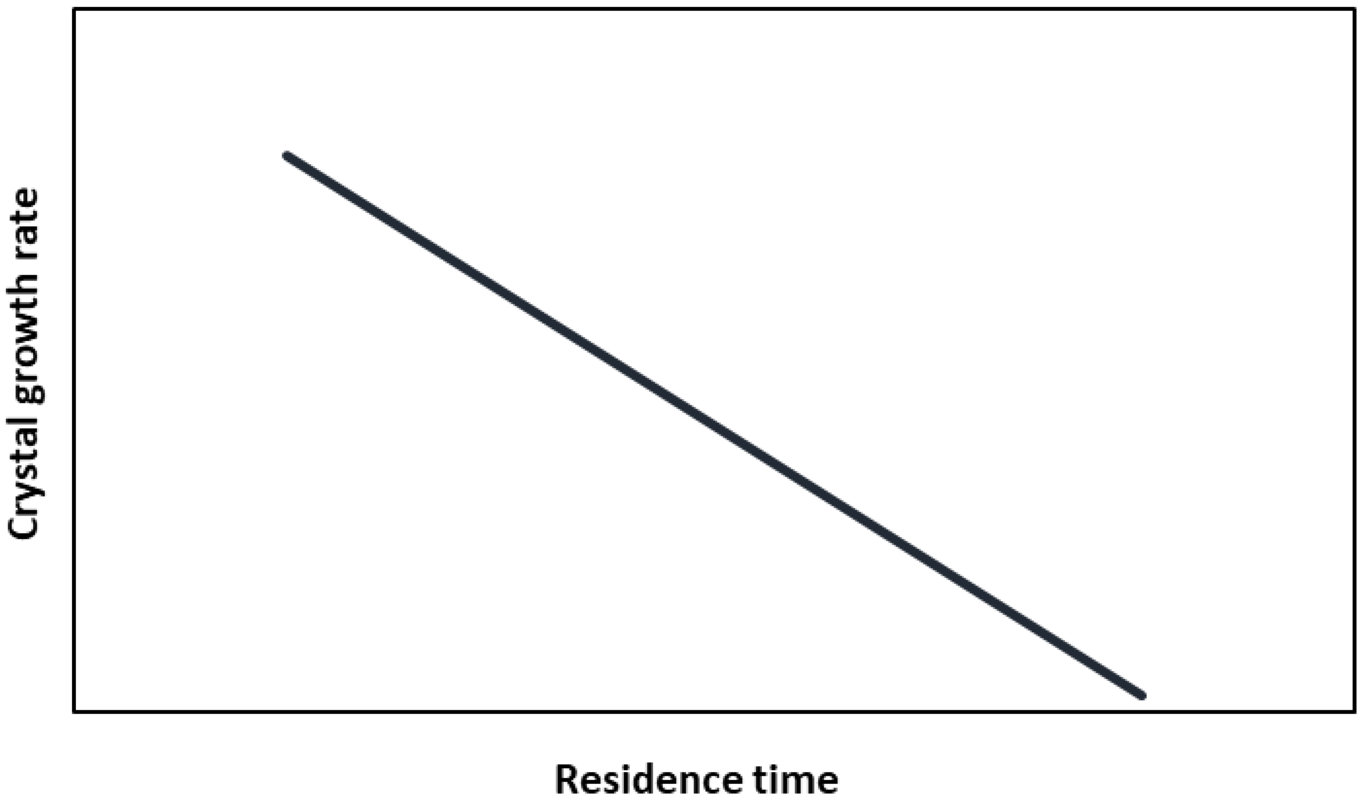
The residence time increases from τ 1 to τ 5 . For the inequalities to hold, the growth rate should decrease with increasing residence time. This agrees with the observations that, on the one hand, an increase in residence time leads to a crystal size distribution with an increased dominant diameter, and on the other hand, an increase in crystal size leads to a decrease in the growth rate. It is observed that each value of residence time is associated with a corresponding value of the crystal growth rate. The graph in Figure 2 presents the qualitative dependence of the crystal growth rate on magma residence time. The data are illustrated by a least squares line with constants a G and b G and for a residence time determined for the attainment of a selected dominant diameter, through Equation (126), an estimate of the value of the corresponding growth rate is attained. It is noteworthy to mention that Equations (124)–(126) form a system that must be solved simultaneously.
It should be emphasized that the experimental procedure is not a prerequisite for the use of the proposed model. If reliable data exist from the literature or crystallization plants and so on, either in the form of equations or as tabled data, they can easily be transformed into an equation of the type of Equation (124), and the constants are set to the technical data section of the application. In the case that no kinetic data are available, the experimental procedure described produces a series of crystal growth rate—residence time numerical value pairs. Other more complex expressions can also be used [19]. Nevertheless, the model can produce results for the flow rates of the streams, the heat loads, the electricity and fuel consumption, and the evaporator sizing even when kinetic data are not available, based on thermophysical properties of the substances and solubility data. Kinetic data are indispensable for crystallizer sizing. It is noteworthy to clarify that Figure 1 and Figure 2 are qualitative representations intended to illustrate the principles of the experimental method. The primary focus of this work is the development and application of a mathematical model for crystallizer design.

2.2. Crystallization Unit Flow Sheet Development

Cooling crystallization is one of the two basic crystallization methods for the production of medium- to large-size crystals. Starting from some fundamental definitions, the term “crystal” characterizes the final product of crystallization, whether it is a solvated or a non-solvated crystal. The term “non-solvated crystal” refers to the part of the molecule of the final crystal that consists of the produced chemical compound free from solvated molecules. If the typical substance A x B y · n S L is considered, where S L is the solvent incorporated into the crystal, the term F c r refers to the flow rate of the total compound that constitutes the “crystal”, while the term F c r a refers to the flow rate of the “anhydrous crystal”. Solubility is expressed as the ratio of the mass fractions of saturated solution X z s , expressed as the mass of solute per unit mass of solvent, and as the mass fraction of saturated solution x z s , expressed as the mass of solute per unit mass of solution, where z is the name of a stream or equipment item. The case examined in this article refers to a feed stream that consists of a solvent and a solute, and these components enter in the form of a liquid solution. The solute gives crystals, and more precisely, their anhydrous part. At the same time, some number of soluble solids is removed as a component of the product moisture, and some other, which in the case of soluble substances can be significant, is taken as a component of the crystallizer overflow. Similarly, the solvent fed may give off a quantity of vapor if the feed solution is depressurized as it enters the crystallizer. Some solvent is incorporated into the solid phase in the form of crystalline solvent molecules in the case of solvated substances, and its amount may also be significant in some cases. The solvent is also removed in the form of moisture (one of its components) of the crystalline product and mainly as crystallizer overflow. Crystalline solvent and solvent vapor may, in many cases, be absent due to the system chemistry and the operation of the crystallizer, respectively. Overflow is the main solvent outflow in order to avoid crystallizer flooding. One important assumption in model development is that the solution in the crystallizer is considered saturated. In practice, it presents a supersaturation, but in industrial applications, supersaturation is usually kept at low levels, and in this case, the influence on mass balances is very limited [19].
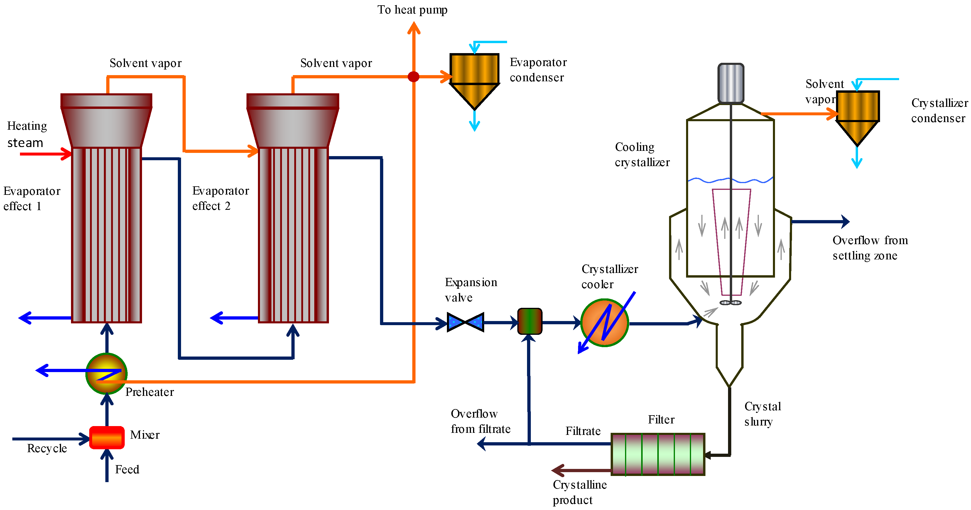
Figure 3 shows the flow sheet of a cooling crystallization unit, including the crystallizer and its ancillary equipment. The feed is combined with a second solution stream in the unit mixer. This stream may be a second feed or, more commonly, a stream originating from the treatment of the crystallizer overflow. The mixer stream is fed to the preheater, which increases the total feed temperature by exploiting vapors produced in the evaporator. The solution is concentrated in the evaporator, which for practical applications is expected to be multiple (in the diagram given, a double forward feed evaporator is used). The evaporator aims to produce a practically saturated feed solution to the crystallizer so that no dissolution of the growing crystals takes place. At the same time, the size of the crystallizer, which has a significantly higher cost than the rest of the equipment, is reduced, as a large amount of solvent is removed before the feed enters the crystallizer. This increases its efficiency as, per unit of feed mass, a larger amount of soluble solids feeds and a larger number of crystals are produced, while solvent overflow and soluble solids loss are limited. Each effect operates at a different pressure (and temperature), and the first effect is heated with heating steam (saturated). The concentrated solution, which is expected to be close to the saturation point in dissolved solids for the prevailing temperature, is fed to the crystallizer at its boiling point temperature. The evaporator and the crystallizer can be connected through an expansion valve that mechanically is a crystallizer component. It may be absent, but its presence gives the flexibility to operate the crystallizer at a pressure lower than that of the evaporator. Thus, a pressure drop occurs that leads to solvent boiling and removal of a quantity of it, contributing to an increase in crystallizer efficiency as the mass of soluble solids is distributed in a smaller quantity of solvent. For a given solubility, a smaller soluble solids quantity can remain in dilution, and a larger quantity is converted into a solid phase; correspondingly smaller are the losses of soluble solids in the overflow. In addition, the production of vapors during expansion binds the latent heat of evaporation and contributes to the reduction of the temperature of the crystallizer feed and a resulting reduction in the thermal power of the crystallizer cooling system. The crystallizer operates at a selected pressure and temperature. The containing solution is subcooled, and the adjustment of the temperature is attributed to the cooling system. During expansion, crystal production is expected in the case that the evaporator solution is close to the saturation point (in solids). The solution, or magma, from the valve outlet is mixed with the crystallizer recycle, and together they constitute its feed. This stream passes through a heat exchanger to achieve the operating temperature. It may be cooled with water when the operating temperature is selected in the range of ~25 °C (or lower in very cold regions or cold seasons) or by using a refrigeration cycle to achieve temperatures of the order of ~0 °C for aqueous solutions. Due to the presence of soluble solids, a depression of the solution freezing point occurs, so temperatures of the order of –5 °C can be applied, increasing the number of soluble solids that crystallize. The solvent vapors produced are condensed in the crystallizer condenser. The installation also includes a filtration unit, and the magma exiting the vessel passes through the filter where the crystalline product is separated, in the form of a dense slurry (filtration cake), from the magma, and the moisture content of the slurry is further reduced mechanically through a press filter or a centrifugation unit and thermally during the subsequent drying. It is assumed that the entire number of crystals is retained on the filter cloth. The filtrate is also taken from the filter and is separated into a crystallizer recycle stream and an overflow. It is considered saturated in solids. The temperature of the filtration unit is assumed to be equal to the operating temperature of the crystallizer. Note that the symbol f that appears in some evaporator variables refers to its last stage.
The mathematical model of the crystallization unit is presented in Table 1. It includes a series of equation blocks that refer to specific items of equipment or data/properties of the streams. Analytically, Equations (1)–(4) refer to the feed solution and Equations (5)–(11) describe the unit mixer. Equations (12)–(41) calculate process variables of the 2-effect evaporator, Equations (42)–(46) refer to the preheater, and Equations (47) and (48) describe the evaporator condenser. Equations (49)–(62) perform the expansion valve calculations, Equations (63)–(95) give the process values of the cooling crystallizer variables, and Equations (96) and (97) describe the crystallizer condenser. Equations (98)–(102) present the enthalpy calculations of the crystallizer, Equations (103)–(105) estimate the cooling equipment of the crystallizer in the case where cooling water is used, or alternatively, Equations (106)–(113) present the cooling equipment when a refrigeration cycle is selected to bring the temperature lower than ambient. Equations (114)–(123) express the mass and volume of the different entities contained in the crystallizer and Equations (124)–(131) refer to the crystallization kinetics. Equations (132)–(138) give the sizing variables of the crystallizer, Equations (139) and (140) estimate two important crystallization parameters, and Equations (141)–(144) present the working pressure of equipment elements. Equations (145)–(149) estimate the overall heat transfer coefficient of the heat exchangers used, Equations (150)–(161) give the solubility of the solution at the conditions of different equipment, and Equations (162)–(169) perform a solubility calculation of different streams at their boiling point temperature. Equations (170) gives the relationship between dry base and wet base moisture of the filtration cake, Equations (171)–(177) estimate the specific heat capacity of the solution at a series of streams, and Equations (178)–(181) present the latent heat of water vaporization at different working temperatures. Equations (182) and (183) estimate the boiling point rise at the evaporator effects, Equations (184)–(193) refer to the density calculation of liquid and vapor streams. Equations (194)–(210) perform the calculation of some statistical variables concerning product quality and Equations (211)–(214) estimate fuel consumption and the efficiency of the crystallization unit.
Most of the equations presented in Table 1 express the mass and energy balances of the individual parts of the crystallization unit. The equations of the evaporator, heat exchangers, and heat pump have been inspired by Maroulis and Saravacos (2003), Saravacos and Maroulis (2001), and Lewis et al. (2015) [20,22,23]. Equations (34) and (35), which calculate the maximum allowable velocity of vapors, have been presented by Souders and Brown in 1934, and the constant C v has the typical value of 0.0244 m/s [24]. Equation (45) is the main expression of the expansion valve and has been presented by Mullin 2001 [25]. Mullin also presented expression 52. Many of the crystallizer equations are original work of the authors, including Equation (64), which has been retrieved by the mass balances of solvent and solute in the crystallizer alone, as well as the equations that refer to the solution recirculation that allow the adjustment of magma density. The concept of deviation of the crystal flow rate into crystal and anhydrous crystal flow rate allows the calculation of the hydrate solvent flow rate and has also been proposed by the authors. The heat pump model has been presented by Grossman et al. (1987) [26]. Equations (127)–(131) have been described by Seader et al. (2011) and consist of a block for the calculation of different kinetic parameters [21]. The dimensioning of the crystallizer has been based on the work of Lewis et al. (2015), while the statistical parameter equations of the crystalline product have been inspired by Wankat (1994) [19,20]. The calculation of volumetric flow rates was inspired by the data generation of AspenPlus. They are necessary for the vessel size calculation of the crystallizer and the liquid-vapor separators of the evaporator. The equations for the properties estimation, such as density and specific heat capacity, are based on Saravacos and Maroulis’s (2001) work [23]. Finally, the solubility of the solutions is estimated by a 2-order polynomial expression, which is very adequate in a very large number of crystallizing systems.
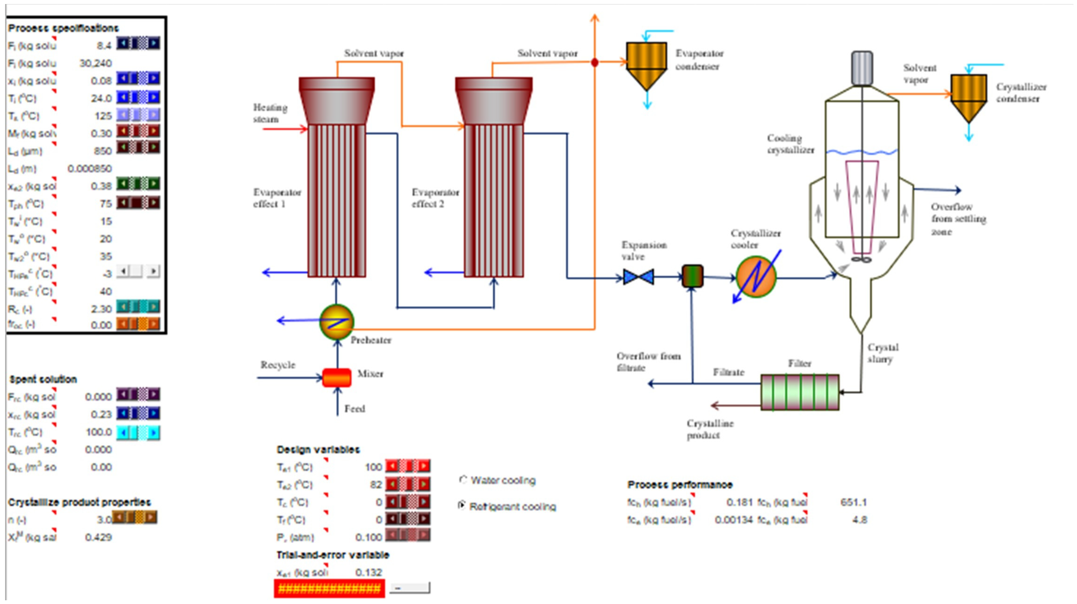
The goal of the mathematical model development is to be used in an application for a cooling crystallizer design. Therefore, it is not restricted to a particular crystallizing system. On the contrary, the system is determined completely from the data the user inputs in the technical data section of the application. When the process specifications are also input in the relative section, the calculation of the process variable values of the crystallization unit automatically takes place, and the results correspond to the system with the specific technical data. The mathematical model was implemented in a spreadsheet. Different programmable environments can be used, such as MathLab, Python, or AspenPlus; the model remains unchanged. In the current presentation, Excel with VBA was used due to the simplicity of the application, its powerful graphical interface, and the familiarity to the users. The calculation is automated with the use of different controls, including scrollbars and buttons that improve the speed and accuracy of the application. It includes the following sections: process specifications, technical data, design variables, which are part of process specifications but adjusted by the designer, and process variables, where the results of the calculations appear. A part of the application interface is shown in Figure 4. It should be noted that each equation can be replaced with a similar one, according to detailed data the user has, and still the process model will be valid. Furthermore, if one or more pieces of equipment are missing from a specific design, the corresponding equations may be omitted without errors in the remaining calculations.

2.3. Case Study

The mathematical model of the crystallization unit that was developed is applied to calculate the size of the equipment, the flow rate of the various streams, and the energy consumption in the case of a solution containing a quantity of substance in dissolved form and the production of the corresponding crystalline form is sought. The design specifications, technical data, and design variables of the unit are given in Table 2. The basic physicochemical data for the design of the processes, with emphasis on the crystallizer, are:
The solubility data of the substance, which for a large number of systems exists in the literature and expresses the equilibrium of the system that is crystallized.
The kinetics of crystallization connects the rate of crystal growth with the residence time and the achievement of the desired granulometry of the product. In cases where reliable kinetic data is not available, their experimental determination is required using methods such as the one described.
Solving the mathematical model for the data provided in Table 2 leads to the calculation of values of the process variables presented in Table 3.

3. Results and Discussion

A series of graphs is presented that depict the effect of various variables on the basic parameters of the unit and provide the sensitivity analysis of basic design parameters of the crystallizer and its auxiliary equipment and how this complementary equipment contributes to the optimization of the crystallizer operation. At the same time, a comparative overview of operational parameters during the mass and energy flow in the individual equipment elements of the unit is also given.
The diagram in Table 4 presents the flow rate of the various entities in the equipment sequence. These entities include the soluble solids and the solvent, which are considered primary, and the crystals, the crystalline (solvated) solvent, and the solvent vapors, which are considered secondary, as they are produced from the initial feed to the individual equipment elements. The equipment numbering is as follows: 1—unit mixer, 2—first evaporator effect, 3—second evaporator effect, 4—expansion valve, 5—crystallizer. The flow rate of the liquid solvent is decreasing as part of it is transformed into solvent vapors during evaporation and expansion and solid crystalline solvent during crystallization. The flow rate of the soluble solids remains constant up to the expansion valve, where crystal production begins via expansion crystallization. For this to happen, the feed solution at the valve must not only be at its boiling point temperature but also very close to the saturation point (in solids). Solvent vapors are produced in the evaporator effects and in the expansion valve and are condensed. In the general case, heat is recovered for energy saving. Their production takes place by adding heat to the evaporator and creating low exit pressure in the valve. In the valve, the flow rate is expected to be significantly lower, compared to the evaporator, due to limited pressure drop. The crystals appear in the expansion valve as the solution becomes colder and denser and its flow rate increases further in the crystallizer with an additional temperature drop. At the same time, the required residence time is provided for their growth to the desired size. The crystalline solvent, in the case of solvated compounds, increases exactly proportionally to the crystals (it is assumed that the substance does not go through different allotropic forms, which is usual for the majority of crystalline substances). From the presented graph, a visual and numerical verification of the mass balances for the fundamental entities undergoing processing, namely the soluble solids and the solvent, is made.
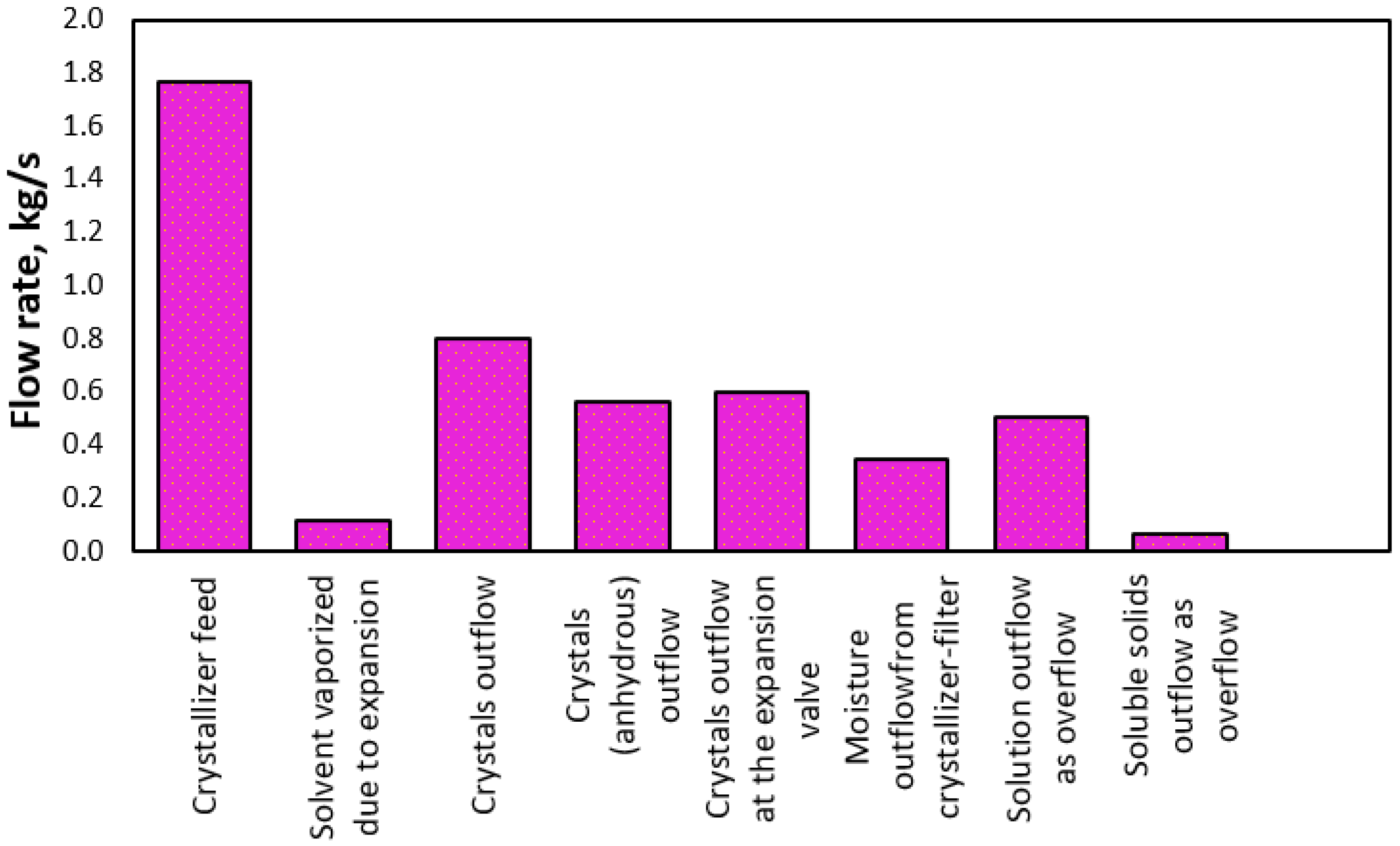
The diagram in Figure 5 illustrates the flow rate of various components/entities to and from the crystallizer. The feed flow rate is the input, includes at least two different components, and is an autonomous stream. The solvent vapor produced during the flash is also an autonomous but single-component stream. It may be zero if the crystallizer pressure is equal to that of the previous process. The flow of crystals (including the crystalline solvent if present) and its moisture constitute a unified stream. The flow of crystals, anhydrous crystals, and moisture is shown separately in the diagram to make clear the contribution of the rate of each entity to the final sludge received. The flow rate of anhydrous crystals is a subset of the total flow rate of crystals, and the different values between them indicate the presence of crystalline solvent (obviously, in the case of a non-solvated product, the flow rates of crystals and anhydrous crystals are identical). The moisture flow rate is an indication of the efficiency of the filtration system and is sought to be limited on the one hand to reduce the loss of soluble solids and on the other hand to reduce energy consumption during drying of the product. The flow rate of crystals created due to expansion is also given for the comparative display of product flow due to pressure drop and additional cooling. The overflow solution is another independent stream and contains more than one component except in the limiting (ideal) case where the feed does not contain impurities and the solubility of the produced substance becomes practically zero at the operating temperature of the crystallizer, in which case the overflow stream consists of the pure solvent. The flow rate of soluble solids in the overflow is an indication of the efficiency of the process, and its theoretical zeroing is sought. The streams of vapor, crystals with their moisture, and overflowing solution constitute the crystallizer effluents. It is noted that the output from the filtration unit is taken as the crystalline product effluent, as the filtrate is recycled to the crystallizer for further processing. Finally, the convergence value of the total mass balance of the crystallizer is shown (at the right end of the graph).
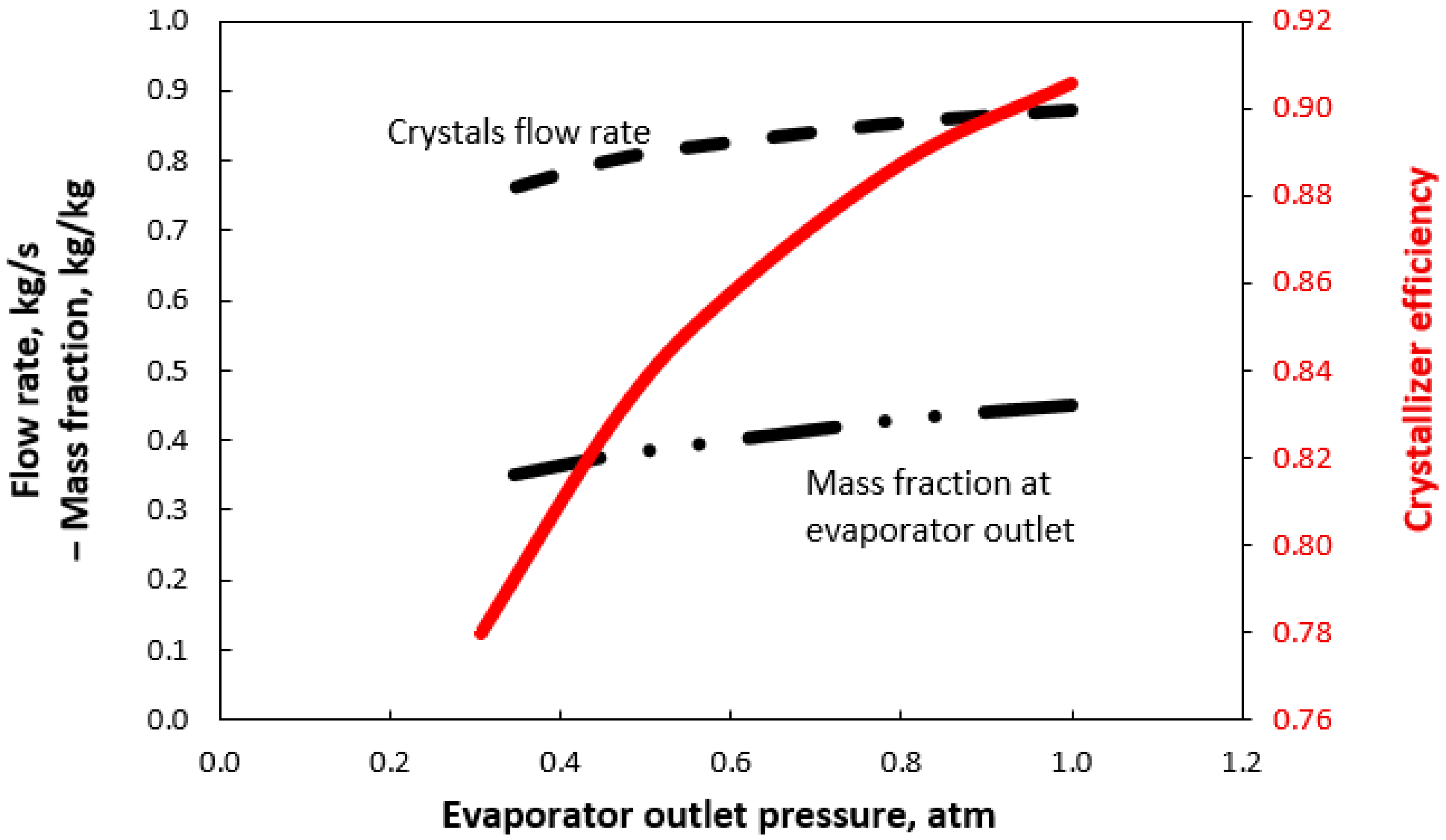
The diagram in Figure 6 shows the change in the production rate of crystals and the crystallizer efficiency as a function of the operating pressure of the last effect of the evaporator, which determines the specifications of the outgoing concentrated solution. The data presented in the graph refers to a solution practically saturated (in solid). The curve at the bottom of the diagram expresses the mass fraction of the solution at saturation. The efficiency increases with increasing evaporator pressure, as this leads to an increase in the boiling temperature of the solution and hence an increase in the mass fraction at saturation. The solution is fed to the crystallizer with an increased number of soluble solids per unit mass. In the crystallization process, the concentration of the solution increases as solvent vapors are removed in the evaporator and through the valve, while preventing any solids from being entrained. This leads to a more concentrated solution that approaches saturation. The solids remain dissolved as long as the solution has not reached saturation. When the solvent continues to vaporize and the temperature decreases, the solution can exceed its saturation concentration, resulting in a state known as supersaturation. At this point, crystal formation begins. In industrial applications, the level of supersaturation is typically maintained at a low level to avoid excessive nucleation. Therefore, it is often assumed that the solution is simply saturated. This assumption allows for the use of saturation data, such as solubility curves, in mass balance calculations.
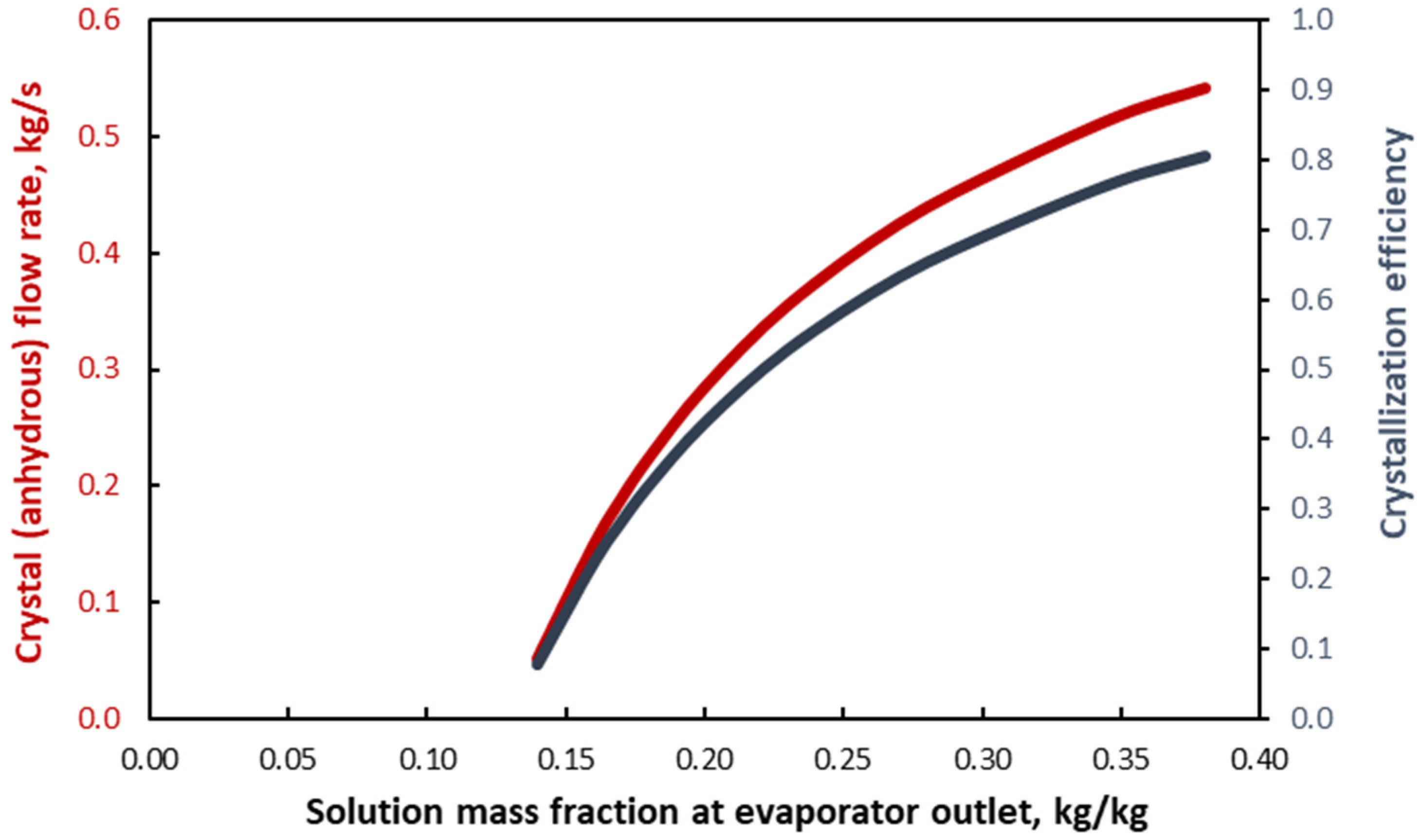
In the presented case, the increase in efficiency amounts to ~15% and mass fraction at saturation by ~28% for a pressure increase from 0.3 to 1.0 atm, with a corresponding elevation in the boiling temperature of the solvent from 70 °C to 100 °C. The increase in the crystal flow rate is ~15%. However, high concentrations of many substances at high temperatures have a corrosive effect on the equipment materials, and care must always be taken to protect it. Soluble solids that remain in the crystallizer magma depend on the solubility at its operating temperature; therefore, the increase in efficiency is due to the enrichment of the feed solution. The graph in Figure 7 illustrates the contribution of the evaporator to the operation of the crystallization unit. For the data presented, the crystallizer and evaporator last effect pressures are equal, i.e., the effect of the solution expansion has been eliminated. It becomes evident that the increase in solution concentration, expressed by its mass fraction at the evaporator outlet, leads to a significant increase in the crystal production rate and the crystallizer efficiency. This is expected, as the ability of solids to remain in a dissolved state is limited by the reduction of the amount of solvent for a given temperature. It is also observed that efficiency tends to zero for feed solutions with low concentration. A dilute feed solution, especially if it is relatively soluble, cannot be crystallized due to not approaching the saturation state, even with significant cooling. The presence of the evaporation system renders the cooling crystallizer flexible and capable of handling any solution for any feed mass fraction. The diagram under consideration should not be confused with the previous one, as in that the effluent solution is always practically saturated (in solids), while in this case the concentration is lower than that at saturation for the prevailing temperature. In the presented case, the solubility at the crystallizer temperature is 0.131 kg soluble solids/kg solution, and solutions with equal or lower mass fraction cannot crystallize.
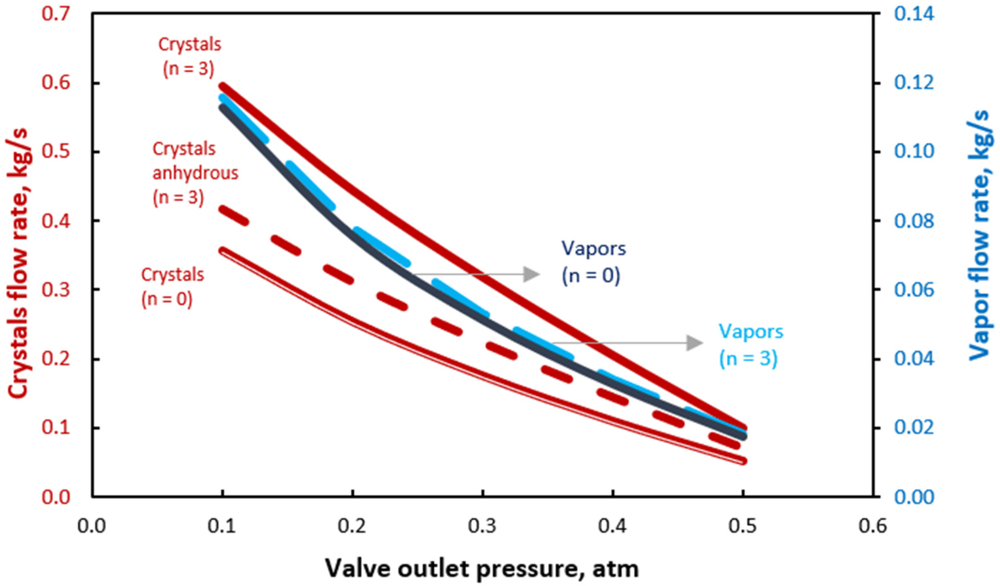
The diagram in Figure 8 depicts the flow rate of crystals, anhydrous crystals, and solvent vapors at the outlet of the expansion valve as a function of its outlet pressure for the case of non-solvated and solvated substances with three molecules of crystalline solvent with the same molecular weight and solubility. In all cases the flow rate increases with a decrease in the outlet pressure. In the case of solvated compounds, the crystal flow rate is obviously increased compared to that of the anhydrous part. In the case of a non-solvated compound, the flow rate is lower compared to that of a solvated one, while the flow rate of its non-solvated entity is apparently identical to that of the solvated one. Of particular interest is the slight increase in the vapor flow rate in the case of solvated substances. This can be explained by the fact that the binding of solvent in crystalline form leads to an increase in the rate of crystal production due to a decrease in the amount of solvent in which the soluble solids are distributed and the release of increased heat in the case of exothermic crystallization, such as the one under consideration, due to the latent heat of crystallization, which increases the amount of vaporized solvent. The reduction of the liquid solvent when part of it is bound in crystalline form also explains the fact that the flow rate of the anhydrous part, in the case of solvated compounds, is increased compared to that of anhydrous substances. From a numerical point of view, it is found that a decrease in pressure from 0.5 atm to 0.1 atm increases the vaporization rate by ~640% and the production of crystals due to expansion by ~595% in the case of the solvated compound.
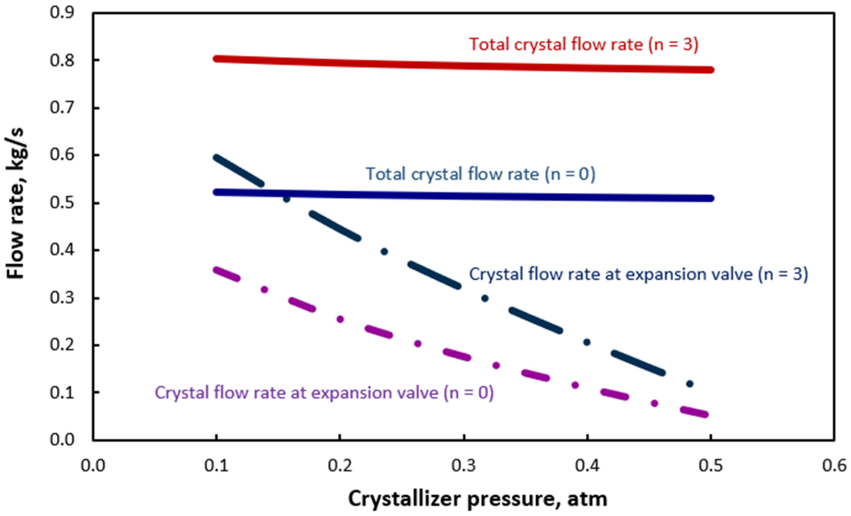
Figure 9 presents the change in the crystal production rate due to the expansion of the solution in the valve and overall, with respect to the operating pressure of the crystallizer. The two almost parallel to the abscissa axis correspond to the total crystal flow rate due to the combined effect of expansion and cooling with a refrigeration cycle. The upper of the two corresponds to a compound with three molecules of crystalline solvent, and the other to a non-solvated substance of the same molecular weight and solubility. Obviously, the solvated compound has a higher flow rate for a given supply of soluble solids. The slight slope they show with respect to the x-axis is due to the reduction in the amount of solvent due to evaporation, which forces a larger number of soluble solids to crystallize, as has already been described in detail. The phenomenon is more pronounced in solvated substances, where the effect of evaporation is combined with the crystallization of a quantity of solvent. The two curves at the bottom of the graph correspond to the rate of crystal production during flash, with the higher one describing the solvated substance and showing higher values due to the crystalline solvent molecules. The rate in this case is strongly related to the pressure drop. The comparison of the flow rates due to exclusive flash and combined flash-cooling, for both the solvated and the non-solvated substance, expresses the strong effect of flash crystallization, which is enhanced as the operating pressure of the crystallizer decreases. It is indicative that in the case of the solvated substance, ~74% of the crystals are produced due to flash, while for the non-solvated substance, the corresponding value is ~68%. The small decrease in the percentage is due to the small drop in the evaporation rate due to the absence of crystalline solvent formation. In more detail, Figure 9 illustrates the cooling effect on crystal production rates from two mechanisms: expansion and mechanical cooling. The dashed lines indicate crystal production due solely to expansion at lower pressure, while the solid lines reflect the combined effect of expansion and mechanical cooling. The vertical distance from the x-axis to a dashed line shows the cooling effect from expansion alone, and the distance between dashed and solid lines represents the additional cooling from the refrigeration system. As the valve outlet pressure decreases, the contribution of expansion to the total crystal flow rate increases, highlighting its efficiency in reducing temperature without incurring additional energy costs.
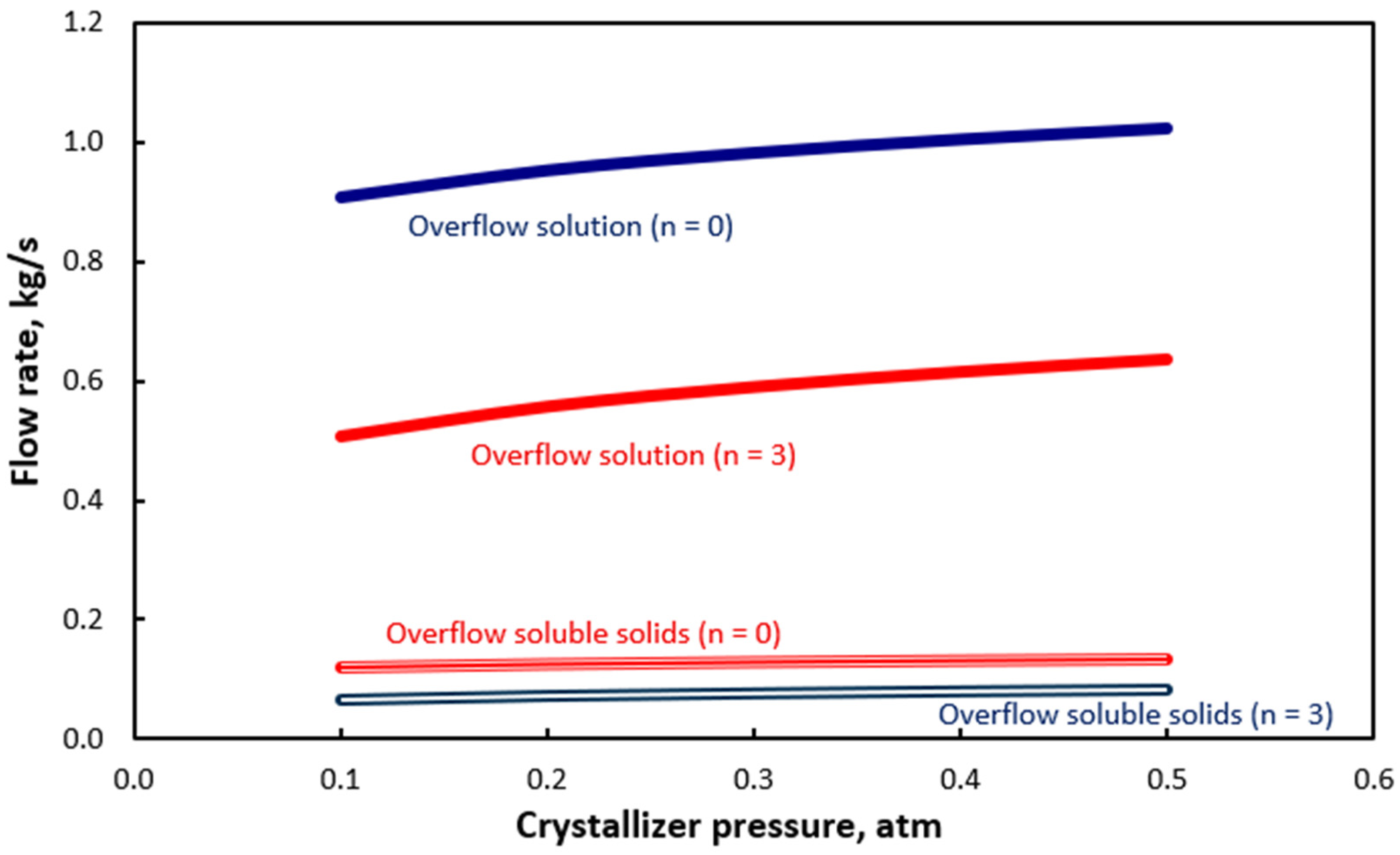
The diagram in Figure 10 provides additional information on the effect of the crystallizer pressure (or equivalently the expansion valve), which refers to its overflow of solution and soluble solids. The increase of both the crystalline solvent molecules and the solution expansion decreases the overflow rate and the removal of soluble solids from the crystallizer. In the case of solvated compounds, the decrease is more pronounced for reasons already mentioned. The ratio of solution and soluble solids flow rates, for each substance, is constant over the entire pressure range due to constant solubility for the operating temperature of the crystallizer. For a pressure drop from 0.5 atm to 0.1 atm, the reduction in overflow is of the order of 12% for non-solvated and 20% for solvated (with three crystalline solvent molecules) compounds of the same type. It is observed, however, that the effect of solvation is significantly stronger, and for three crystalline solvent molecules it is of the order of 40%. It has to be mentioned that in the presented case the pressure of the solution at the valve inlet (evaporator outlet) is 0.51 atm, and the development of a vacuum for expansion occurs for a crystallizer pressure of 0.5 atm and lower. For a higher crystallizer pressure, no solution expansion takes place.
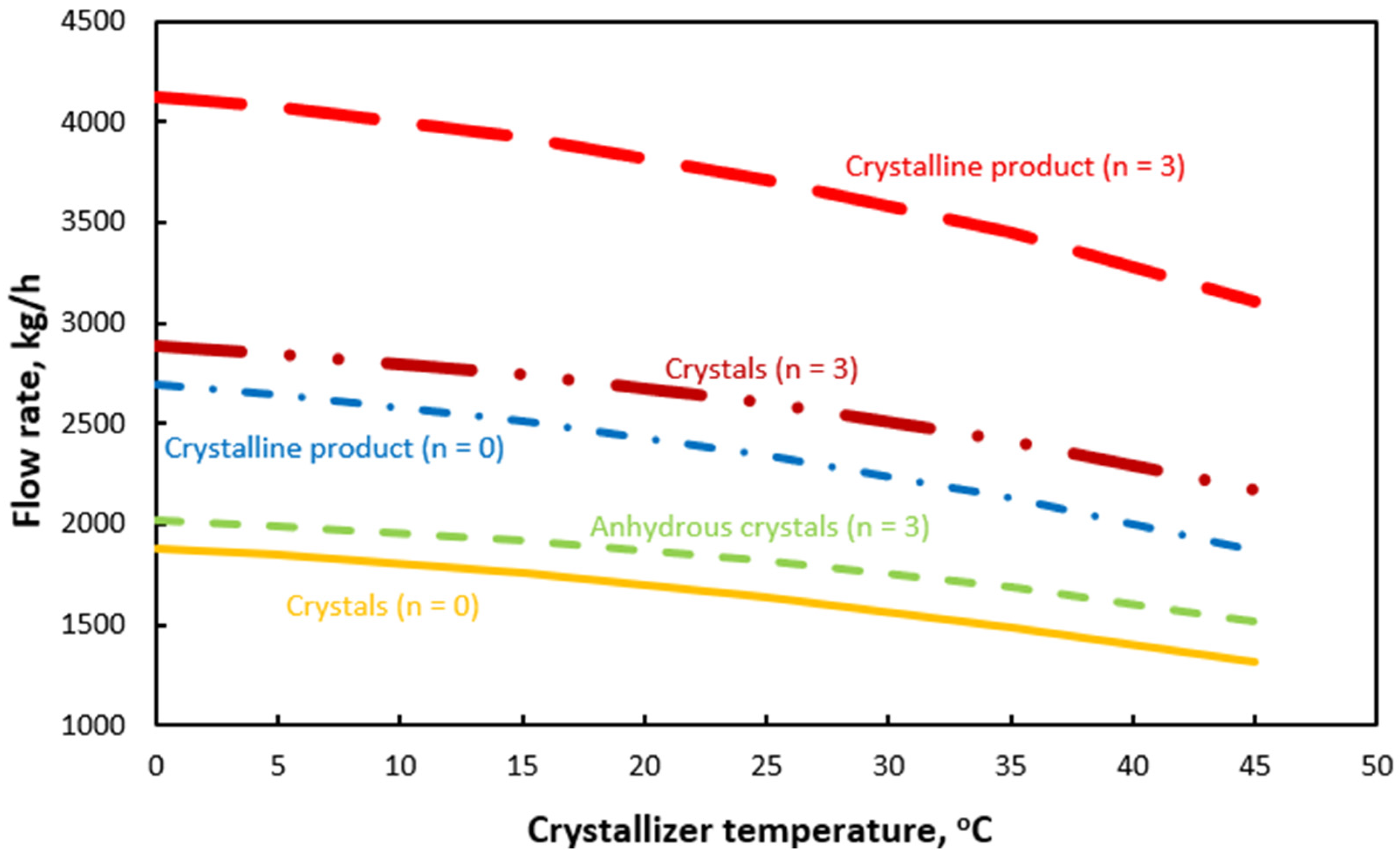
The graph in Figure 11 illustrates the change in the flow rate of crystals and crystalline product, including its moisture, at the crystallizer outlet as a function of its operating temperature in the case of a non-solvated substance and a solvated one of the same type hydrated with three solvent molecules. It is observed that the decrease in operating temperature increases the compound production rate as the solubility of the substance decreases and the solid phase expulsion increases. In the case under consideration, the increase in crystals amounts to ~35% for a non-solvated and ~28% for a solvated compound for a temperature decrease from 45 °C to 0 °C. The increased value in the case of the non-solvated substance is attributed to the fact that it does not carry the inert, in terms of solubility, part of the crystalline solvent. As explained above, the increase in solvation increases the crystal flow rate for a given temperature.
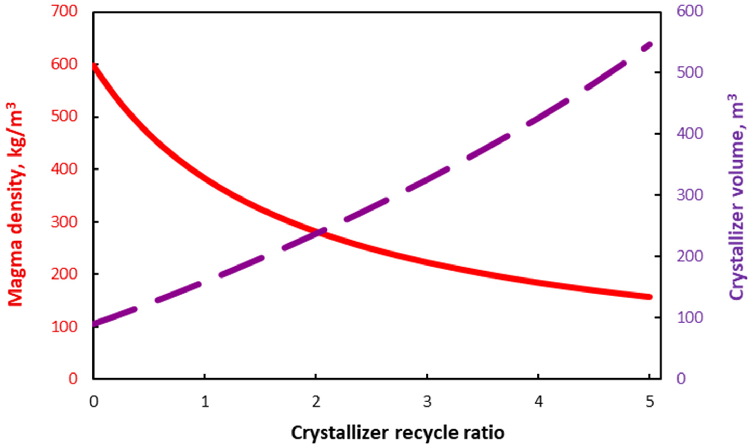
The diagram in Figure 12 illustrates the dependence of magma density and crystallizer size (the volume of the vessel is determined by the magma volume through the size increase factor) on the crystallizer recirculation ratio. It is observed that the effect is particularly significant for both variables. In detail, the increase in recirculation increases the amount of saturated solution entering the crystallizer, and since the crystal production rate is determined by the operating temperature through the solubility of the system (for a given initial feed to the unit), the magma density decreases due to its dilution. Obviously, increasing the feed solution to the crystallizer requires a larger vessel to manage it. It is noted that the total feed is the sum of the “fresh” feed from an upstream process and the recirculation. In the examined case, the crystallizer volume increases by ~500% for a fivefold increase in recirculation, while the magma density undergoes a corresponding decrease of ~74% (compared to zero recirculation). The role of recirculation in regulating magma density is fundamental given that desired values of magma density range from 200 to 400 kg/m3, so that on the one hand the crystallizer efficiency does not drop to low levels due to limited feed of soluble solids, and on the other hand the friction of the crystals between themselves and with the equipment, and their consequent fragmentation, is limited, and the flow of the magma is ensured through appropriate pumps.
The diagram in Figure 13 shows the variation of the crystal growth rate as a function of the recirculation ratio of the crystallizer. It is therefore observed that the selection of the equipment design variables values has an effect on the kinetics of the unit. The increase in recirculation causes dilution of the magma, as described in Figure 12, resulting in a decrease in the crystal growth rate and consequently an increase in the residence time to achieve crystals of the desired size. In the case examined, the reduction is of the order of ~40% for a fivefold increase in recirculation.
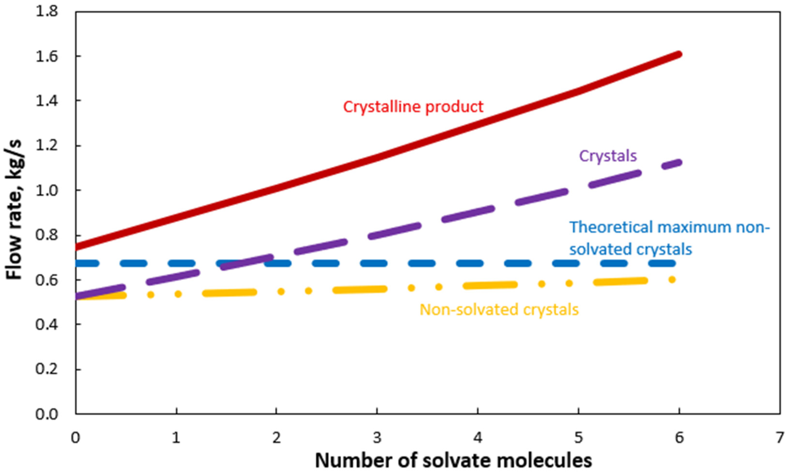
The graph in Figure 14 presents the flow rate of non-solvated and solvated crystals at the crystallizer outlet as a function of the number of solvate molecules per crystal molecule. The corresponding rate of the crystalline product (slurry), which includes its moisture content, is also shown, as well as the theoretical maximum flow rate of non-solvated crystals. The latter remains absolutely constant, as it expresses the maximum number of soluble solids that can be crystallized, and for a 100% efficiency is determined solely by the feed of soluble solids to the unit. Of particular interest is the increase in the production rate of non-solvated crystals as a function of solvate molecules increase under constant solubility due to the constant crystallization temperature and given feed, which is due to the fact that the solvent binding by the product distributes the soluble solids in a smaller amount of remaining solvent, resulting in the excess amount being crystallized.
The graph in Figure 15 illustrates the flow rates of the solution and soluble solids of the crystallizer overflow as a function of the number of crystalline solvent molecules that are bound by the substance and incorporated into the crystal lattice of the final product in crystalline form. It is observed that the increase in solvate molecules, for appointed operating parameters, leads to a significant reduction in the rate of overflow, which in the case of non-solvated substances is removed from the crystallizer (in the form of a saturated solution entraining soluble solids). Correspondingly, the overflow of soluble solids is limited as the production of crystals also increases in the form of their non-solvated part. It is characteristic that when the solution is fed to the crystallizer in a state of almost saturated solution (in solids), there is a certain value of solvate molecules that drives the overflow rate to zero. This indicates that the entire amount of solvent fed is bound to the crystal lattice of the substance, and the losses of substance from the crystallizer tend to zero. In the presented case, this occurs for seven crystalline water molecules, when a negative value of the overflow rate appears. This has no physical significance. That negative value indicates that the solvent is bound, and either a substance with a smaller number of solvate molecules than that predicted by physical chemistry will be produced in order to be at a stable state at the operating temperature or the solvent feed rate to the crystallizer should be increased by producing a more dilute solution in the last stage of the evaporator. Of course, the number of solvate molecules is determined by the physical chemistry of the substance and is not a matter of manipulation by the designer. On the other hand, that number has a significant impact on the recovery and recirculation of the overflow and its corresponding energy cost.
The diagram in Figure 16 shows the solvent vapor flows from the various equipment elements of the unit. In the flow sheet under consideration, vapors are produced in the two evaporation effects and in the expansion valve. It is evident that the vapor production in the evaporator, which is carried out through the heat transfer from the heating steam, is significantly larger than that of the valve, which is due to the expansion of the solution due to a pressure decrease in the flow channel. It also becomes evident in this case that the presence of the evaporator is particularly important for the operation and flexibility of the unit, as it provides the ability for solvent removal at any desired level until saturation (in solids) is achieved.
The diagram in Figure 17 shows the concentration (mass fraction) of the solution and the corresponding saturation concentration in the feed and the main equipment components. The solution tends to saturation (in solids) only at the outlet of the last evaporation effect, ensuring that no solids will settle in undesirable equipment parts of the flow sheet. Furthermore, as the temperature decreases towards the last effect, the saturation concentration also decreases for the case of an evaporator fed to the first (hotter) effect (forward-feed evaporator). In the crystallizer, the saturation concentration corresponding to the operating pressure is significantly higher than that corresponding to the operating temperature since it is a cooling crystallizer, and the magma is in a subcooled state (with a significant degree of subcooling in many cases). In more detail, in Figure 17, ‘solubility’ indicates the maximum concentration of soluble solids the solvent can hold without crystallization, which varies with temperature. As the solution flows through the system, its temperature changes, affecting solubility. During evaporation, the solution approaches saturation, shown where the solubility and concentration lines nearly converge. In the crystallizer, the temperature drop reduces solubility, leading to crystallization of excess solids.
Figure 18 shows a diagrammatic representation of the thermal loads (heat power) of the crystallization unit, which includes the loads of the first and second evaporation effects, the preheater, the evaporator condenser, the expansion valve, the crystallizer, and the heat pump condenser. It is observed that the largest loads occur in the evaporator, which is expected as they are related to the latent heat of vaporization of liquid and remove a particularly large amount of solvent from the feed. They constitute the main energy (and fuel) consumption of the unit. The preheater load, on the other hand, constitutes an energy gain for the unit as it is recovered from the removed solvent vapors. The evaporator condenser load indicates energy that is discharged to the environment and constitutes a significant loss. The goal of an integrated design is its use, e.g., via a heat pump (heat pump evaporator), considering that it is related to a relatively high temperature discharged stream. The load of the expansion valve does not burden the fuel consumption, as it is offered through the pressure difference between the evaporator and crystallizer. The thermal load of the crystallizer is removed from the unit through the refrigeration cycle. It is related to fuel consumption through the production of electricity and not heating steam as occurs in the evaporator (a cogeneration boiler delivers heat and electricity simultaneously). Finally, the heat load of the condenser of the crystallizer heat pump constitutes an additional energy loss of the unit, which can hardly be recovered for utilization due to the low temperature of the streams in the heat exchanger.
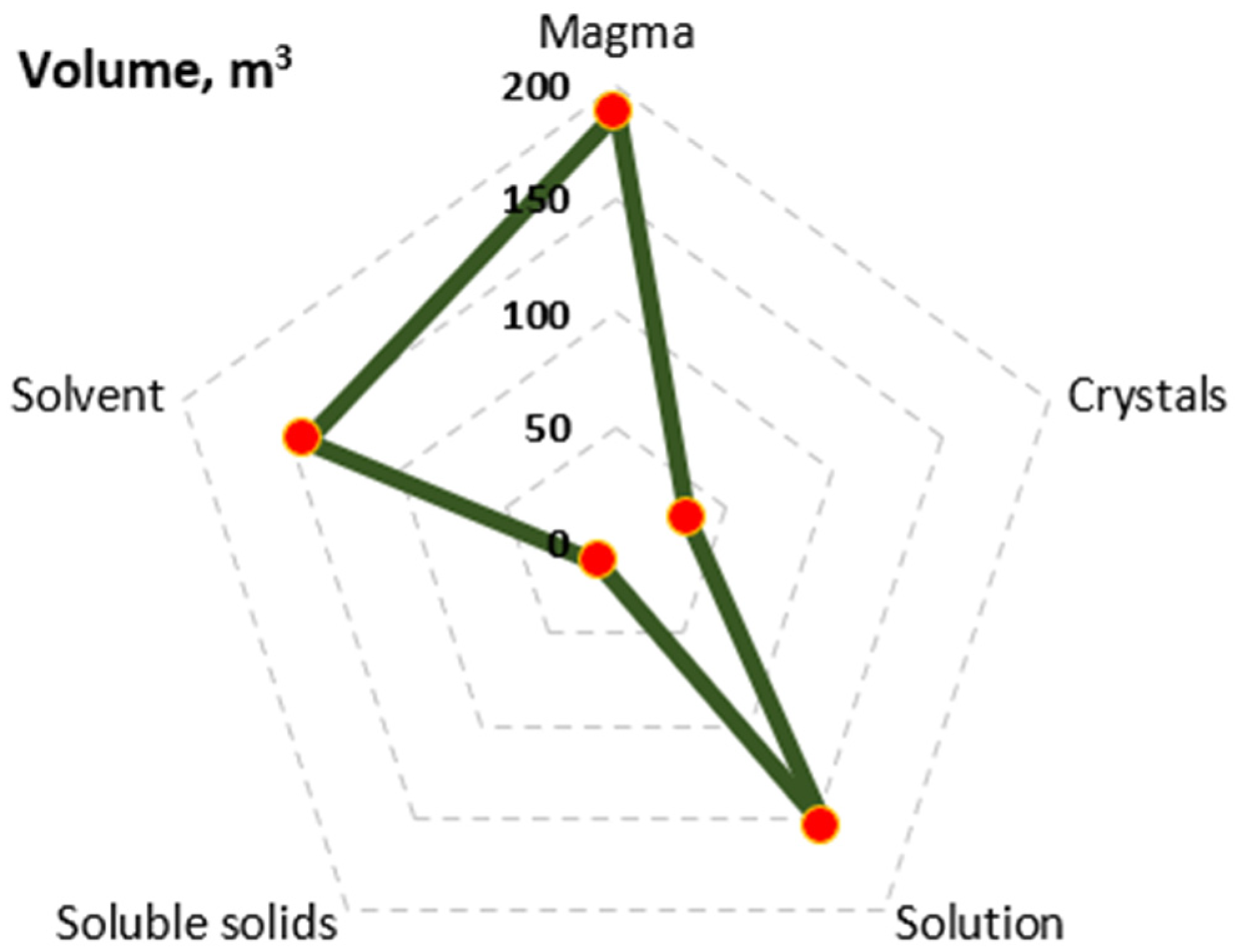
The graph in Figure 19 depicts the volumetric distribution of the entities contained inside the crystallizer, which includes the magma, the crystals, the magma solution (mother liquor), the soluble solids, and the solvent. A significant percentage of volume occupied by the solution and the solvent in relation to that of the magma is observed. Crystals occupy a relatively low percentage of volume, both due to their increased density and due to the fact that the magma density is controlled (through temperature and recirculation) to be kept far from high values. Specifically, the crystals constitute 17.7% of the magma volume, while the solvent constitutes 76% of the magma volume in the presented case. The volume of soluble solids is small compared to the rest and amounts to 6.2% of the magma volume. This demonstrates that crystallization is carried out with good efficiency. The theoretical optimum is the soluble solids volume reduction to zero for full utilization of the feed. It is noted that soluble solids also have an increased density compared to liquid substances.
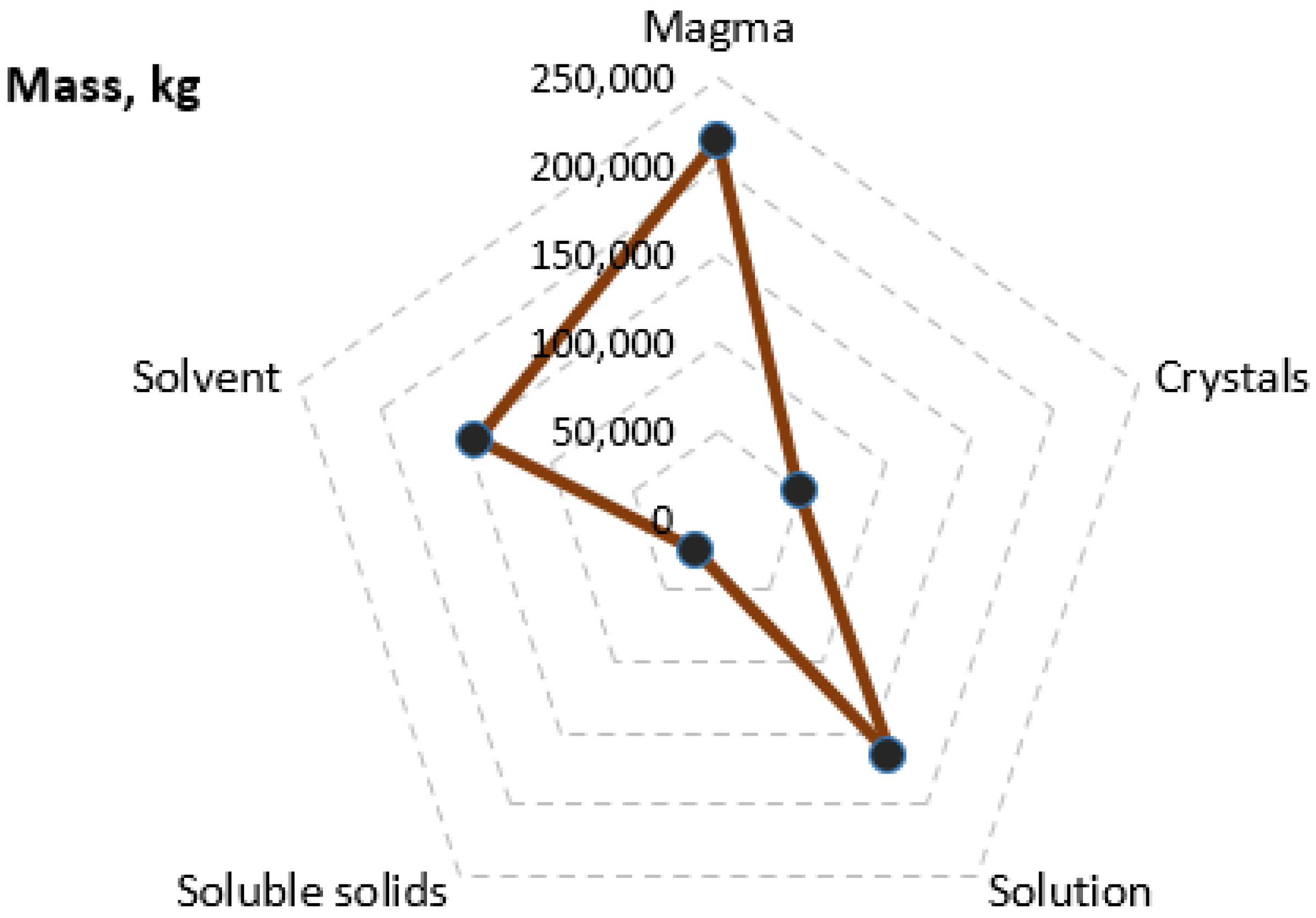
The corresponding diagram to the previous one, which refers to the mass, is shown in Figure 20 and gives the mass distribution of the entities present in the crystallizer (magma, crystals, solution, solvent, and soluble solids). Magma is the sum of solution (mother liquor) and crystals, while solution is the sum of solvent and soluble solids; therefore, through the graph, visual verification of the validation of mass balances is performed. From a numerical point of view, crystals constitute 22.9% of the magma. The mass ratio of soluble solids to magma solution is identical to the mass fraction of soluble solids at saturation at crystallizer temperature (13.1%). Correspondingly, the mass ratio of soluble solids to solvent is identical to the mass ratio at equilibrium (saturation) at crystallizer temperature (15.1%). The above constitute controls for the correctness of the calculations and the convergence of the mass balances. It is observed that the mass of soluble solids constitutes 10.1% of the mass of the magma, and although it is comparatively small, it is nevertheless proportionally increased in relation to the volume percentage (of the previous graph) by 62%. This is due, as already mentioned, to the increased density of solid substances. In addition, in the presented case, the substance has significant solubility even at very low temperatures. The estimation of losses in terms of mass is considered more correct, as it is not affected by the density values, which can differ greatly between different substances.
Figure 21 gives the diagrammatic representation of the change in the required residence time and the corresponding size of the crystallizer as a function of the desired size of the crystals produced. It is well known that the residence time depends not only on the type of substance but also on the size required for the product, which is expressed by the dominant crystal diameter. This dependence is mathematically attributed to the kinetics of crystallization. The production of larger crystals requires more time not only to develop a more extensive lattice but also because the growth rate decreases with increasing particle size. This explains the fact that the increase in the vessel size becomes more pronounced for large crystal sizes, and the linearity between crystal diameter and crystallizer volume does not hold. For an increase in size from 450 to 650 μm, the residence time and the crystallizer volume increase by 48% and 48%, respectively. For an increase in crystal size from 650 to 850 μm, the corresponding values are 54% and 54%. It is not surprising that the percentage values for the two variables are exactly equal in each case, since for the remaining parameters given, the crystallizer size is a linear function of the residence time, as can be seen from the corresponding relationship.
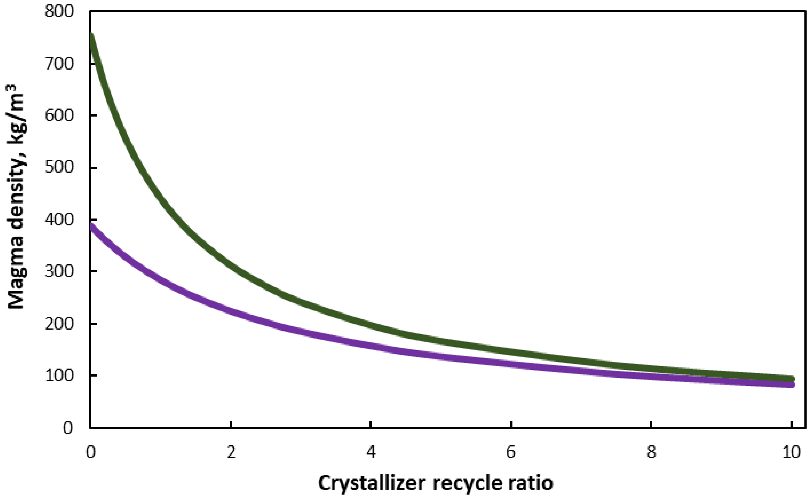
Figure 22 diagrammatically represents the magma density of the crystallizer as a function of the recycle ratio in the case where the produced substance is non-solvated or solvated with five molecules of crystalline solvent per substance molecule. As expected, the increase in recirculation, which is in practice a saturated solution at the operating temperature of the crystallizer-filter, reduces the magma density. Essentially, recirculation plays the role of a diluent by changing the magma density without causing dissolution of the crystals that grow, as it is saturated with substance for the operating temperature. It is useful for achieving the desired magma density, which affects the crystallization kinetics. In addition, magma density affects the quality of the product, as its excessive increase leads to intense friction between the particles and their breakage. It is found that in the case of solvated substances, for a given feed, the magma density can become very high, and the recycle ratio acquires a much more important significance in regulating it to the desired value. The high increase in magma density with the increase in solvate molecules is due to the fact that the mass of the crystals is greater for a given non-solvated crystal part, and furthermore, the amount of solvent is limited due to its binding to the crystal lattice. The recirculation of solution cannot be replaced by the feed of pure solvent, as this, being unsaturated, would solubilize a quantity of crystals.

4. Conclusions

The developed mathematical framework successfully integrates a cooling crystallizer with auxiliary equipment—including a multi-effect evaporator, heat pump, and expansion valves—into a unified design model. By coupling thermodynamic principles with experimentally derived crystallization kinetics, the study demonstrates robust prediction of key operational parameters, such as heat duties, crystallizer volume, and residence time requirements. The case study underscores the critical role of auxiliary equipment in enhancing crystallizer efficiency, particularly through solvent removal and controlled pressure regulation. Notably, the model elucidates the pronounced impact of solvate molecules on crystal yield and overflow dynamics, while highlighting the trade-offs between recirculation ratios, magma density, and crystal growth kinetics. These insights provide a validated pathway for optimizing energy consumption and equipment sizing in industrial crystallization processes, offering a scalable approach to achieving target product specifications.
While the model exhibits strong predictive capabilities under steady-state conditions, its current formulation omits transient behaviors and supersaturation dynamics, which may limit applicability to highly dynamic systems. Future research should prioritize integrating population-balance models to account for crystal size distribution variability and secondary nucleation effects. Experimental validation across diverse chemical systems and operating regimes remains essential to refine kinetic parameters and enhance model generalizability. Furthermore, embedding this framework within broader process simulation platforms could facilitate real-time optimization and advanced heat integration strategies. Addressing these aspects will not only bridge existing gaps but also extend the model’s utility to emerging applications in pharmaceutical and waste recovery industries, aligning with global demands for sustainable and energy-efficient separation technologies.

Author Contributions

Conceptualization, P.A.M. and A.P.; methodology, P.A.M. and A.P.; software, P.A.M. and A.P.; validation, P.A.M. and A.P.; formal analysis, P.A.M. and A.P.; investigation, P.A.M. and A.P.; resources, P.A.M. and A.P.; data curation, P.A.M. and A.P.; writing—original draft preparation, P.A.M. and A.P.; writing—review and editing, P.A.M. and A.P.; visualization, P.A.M. and A.P.; supervision, P.A.M. and A.P.; project administration, P.A.M. and A.P.; funding acquisition, P.A.M. and A.P. All authors have read and agreed to the published version of the manuscript.

Funding

This research received no external funding.

Conflicts of Interest

The authors declare no conflict of interest.

Nomenclature

A e 1 (m2)Evaporator first effect heat transfer area
A e 2 (m2)Evaporator second effect heat transfer area
A A n t (–)Antoine constant for solvent (water)
a b p r (–)Boiling point elevation constant
a C T (–)Solubility—temperature constant
A c v c s (m2)Crystallizer cross sectional surface area based on maximum allowable vapor velocity
A e 1 c s (m2)Cross sectional surface area of liquid-vapor separator of evaporator first effect
A e 2 c s (m2)Cross sectional surface area of liquid-vapor separator of evaporator second effect
a G (–)Crystal growth rate—residence time constant
A H P c c (m2)Heat transfer area of crystallizer heat pump condenser
A H P e c (m2)Heat transfer area of crystallizer heat pump evaporator
A p h (m2)Preheater heat transfer area
a U (–)Overall heat transfer coefficient constant
a w (–)Latent heat of vaporization—temperature constant for solvent (water)
A w c (m2)Crystallizer heat exchanger surface area for water cooling
B o (# nuclei/m3/s)Nucleation rate per unit magma (solution) volume
B A n t (–)Antoine constant for solvent (water)
b b p r (–)Boiling point elevation constant
b C T (–)Solubility—temperature constant
b G (–)Crystal growth rate—residence time constant
b p r e 1 (°C)Evaporator first effect boiling point elevation
b p r e 2 (°C)Evaporator second effect boiling point elevation
b U (–)Overall heat transfer coefficient constant
b w (–)Latent heat of vaporization—temperature constant for solvent (water)
C A n t (–)Antoine constant for solvent (water)
c C T (–)Solubility—temperature constant
C O P c (–)Crystallizer heat pump coefficient of performance
C p c i (kJ/kg/°C)Specific heat capacity of crystallizer feed solution (downstream mixing of valve outlet solution and recycling solution)
C p e x p (kJ/kg/°C)Solution specific heat capacity at expansion valve outlet
C p e 1 (kJ/kg/°C)Solution specific heat capacity at evaporator first effect
C p e 2 (kJ/kg/°C)Solution specific heat capacity at evaporator second effect
C p c i (kJ/kg/°C)Feed solution specific heat capacity
C p m x (kJ/kg/°C)Solution specific heat capacity at mixer outlet
C p m s t (kJ/kg/°C)Solution specific heat capacity in the crystallizer
C p r c (kJ/kg/°C)Crystallizer heat pump fluid heat capacity
C p r c (kJ/kg/°C)Recycling solution specific heat capacity
C p s (kJ/kg/°C)Solute heat capacity
C p w (kJ/kg/°C)Liquid solvent (water) heat capacity
C v (–)Constant for maximum allowable vapor velocity
c w (–)Latent heat of vaporization—temperature constant for solvent (water)
D c (m)Crystallizer diameter
D c m (m)Crystallizer diameter based on magma holdup volume
D c v (m)Crystallizer diameter based on maximum vapor velocity
D e 1 c s (m)Cross sectional diameter of liquid-vapor separator of evaporator first effect
D e 2 c s (m)Cross sectional diameter of liquid-vapor separator of evaporator second effect
E c c (kW)Crystallizer heat pump compressor electrical power
f c (kg fuel/s)Total fuel consumption
F c e (kg solvent vapor/s)Vapor flow rate to evaporator condenser
F c m o (kg magma/s)Outlet magma flow rate from the crystallizer (feed to its filter)
f c e (kg fuel/s)Fuel consumption for electricity generation
f c h (kg fuel/s)Fuel consumption for heating steam generation
F c i (kg solution–magma/s)Crystallizer total inlet solution and crystals flow rate downstream expansion (excluding vapor flow rate)
F c L (kg solution/s)Crystallizer total inlet solution flow rate (solution flow rate at crystallizer mixer)
F c L s l (kg solvent/s)Crystallizer total inlet solvent flow rate downstream expansion
F c L s s (kg soluble solids/s)Crystallizer total inlet soluble solid flow rate downstream expansion
F c r a (kg crystals anhydrous/s)Anhydrous crystals or anhydrous part of solvated crystals outlet flow rate
F c r M f (kg crystalline product/s)Outlet flow rate of crystalline product, including its moisture, at filter outlet
F e c (kg vapor/s)Vapor flow rate to evaporator condenser
F m (kg solution/s)Solution flow rate at mixer outlet
F c t i (kg solution/s)Crystallizer total inlet solution flow rate upstream expansion valve
F c r (kg crystals/s)Crystals (hydrated) outlet flow rate
F c r a m a x (kg crystals anhydrous/s)Theoretical maximum anhydrous crystalline product flow rate
F c o f (kg solution/s)Overflow flow rate from filtrate stream
F c o s l (kg solvent/s)Solvent flow rate exiting crystallizer as overflow (at liquid state)
F c o s s (kg soluble solids/s)Soluble solids flow rate exiting crystallizer as overflow
F c o s t (kg solution/s)Solution flow rate exiting crystallizer as overflow
F c o s z (kg solution/s)Overflow flow rate from the calming zone
F e 1 s l (kg solvent/s)Solvent flow rate at the evaporator first effect outlet
F e 1 s s (kg soluble solids/s)Soluble solids flow rate at the evaporator first effect outlet
F e 2 s l (kg solvent/s)Solvent flow rate at the evaporator second effect outlet
F e 2 s s (kg soluble solids/s)Soluble solids flow rate at the evaporator second effect outlet
F e x p (kg solution/s)Solution flow rate at the expansion valve outlet
F c r e x p (kg crystals/s)Crystals flow rate at the expansion valve
F e x p s l (kg solvent/s)Solvent flow rate at the expansion valve outlet
F e x p s l h (kg solvent/s)Hydrated solvent flow rate at the expansion valve outlet
F e x p s s (kg soluble solids/s)Soluble solids flow rate at the expansion valve outlet
F i (kg solution/s)Feed solution flow rate
F i s l (kg solvent/s)Solvent flow rate in the feed stream
F i s s (kg soluble solids/s)Soluble solids flow rate in the feed stream
F f M (kg solution/s)Moisture flow rate exiting crystallizer (including its filter)
F f l (kg solution/s)Filtrate flow rate
F L 1 (kg solution/s)Evaporator first effect outlet solution flow rate
F L 2 (kg solution/s)Evaporator second effect outlet solution flow rate
F M s l (kg solvent/s)Moisture solvent flow rate exiting crystallizer (including its filter)
F m s l (kg solvent/s)Solvent flow rate in the mixer outlet
F M s s (kg soluble solids/s)Moisture soluble solids flow rate exiting crystallizer (including its filter)
F m s s (kg soluble solids/s)Soluble solids flow rate in the mixer outlet
F r (kg solution/s)Recycling solution flow rate
f r c o (–)Fraction overflow flow rate from the calming zone
F p h (kg steam/s)Vapor flow rate to evaporator preheater
F r c (kg refrigerant/s)Crystallizer heat pump fluid flow rate
F s l h ()Hydrated solvent flow rate exiting crystallizer
f v (–)Vessel increase factor
F V 1 (kg vapor/s)Evaporator first effect vapor flow rate
F V 2 (kg vapor/s)Evaporator second effect vapor flow rate
F V t (kg vapor/s)Evaporator total vapor flow rate
F w e c (kg cooling water/s)Cooling water flow rate to evaporator condenser
G (m/s)Crystal (linear) growth rate
G r e f (m/s)Reference crystal linear growth rate
H c o (kW)Enthalpy of solution overflows crystallizer
H c r (kW)Latent heat of crystallization
H c m (kW)Solution/magma enthalpy at crystallizer mixer outlet
H c r M (kW)Crystalline product enthalpy
i (–)Exponent of the kinetic equation
j (–)Exponent of the kinetic equation
k v (–)Crystal volume shape factor
L d (μm)Dominant size of crystalline product
M c (kg moisture/kg slurry)Crystalline product moisture content (wet basis)
M f (kg moisture/kg slurry)Crystalline product moisture content at the filter outlet (wet basis)
m c c r (kg crystals)Crystals mass in the crystallizer
m c s t (kg solution)Magma solution mass in the crystallizer
m m g (kg magma)Magma mass in the crystallizer
m c s s (kg soluble solids)Soluble solids mass in the crystallizer
m c s l (kg solvent)Solvent mass in the crystallizer
m s (kg heating steam/s)Heating steam flow rate
m s / c (kg solvent/mol anhydrous crystal)Mass of solvent per molecular mass of anhydrous crystal
M T (kg crystals/m3 magma)Magma density
M T r e f (kg crystals/m3 magma)Reference magma density
M W s (kg/mol)Anhydrous solid molecular weight
M W s l (kg/mol)Solvent molecular weight
n (–)Number of hydrate molecules per solid molecule
N c r (# crystals/s)Crystal number production rate
n c r (–)Crystallization recovery (efficiency)
n e (–)Electrical efficiency
n h (–)Thermal efficiency
n o (# nuclei/m4)Population density of nuclei (number density)
P c (atm)Crystallizer pressure
P e 1 (atm)Evaporator first effect pressure
P e 2 (atm)Evaporator second effect pressure
P s (atm)Heating steam pressure
Q c (kW)Crystallizer heat duty
Q c e (kW)Evaporator condenser heat duty
Q c i (m3 solution–magma/s)Solution/magma volumetric feed flow rate to the crystallizer (excluding vapors)
Q c H P c (kW)Crystallizer heat pump condenser heat duty
Q c L (m3 solution/s)Total crystallizer feed solution volumetric rate
Q c m o (m3 magma/s)Outlet magma volumetric flow rate from the crystallizer
Q c o f (m3 solution/s)Overflow volumetric flow rate from filtrate stream
Q c o s z (m3 solution/s)Overflow volumetric flow rate from the calming (settling) zone
Q c r (m3 crystals/s)Crystals volumetric flow rate
Q c r e x p (m3 crystals/s)Crystals volumetric flow rate at the expansion valve outlet
Q e H P c (kW)Crystallizer heat pump evaporator heat duty
Q e 1 (kW)Evaporator first effect heat duty
Q e 2 (kW)Evaporator second effect heat duty
Q e c (kW)Evaporator condenser heat duty
Q e x p s t (m3 solution/s)Solution volumetric flow rate at the expansion valve outlet
Q e x p V (m3 vapor/s)Volumetric flow rate of solvent vaporized due to expansion in the crystallizer
Q f l (m3 solution/s)Filtrate volumetric flow rate
Q i (m3 solution/s)Feed solution volumetric flow rate
Q L 1 (m3 solution/s)Evaporator first effect outlet solution volumetric flow rate
Q L 2 (m3 solution/s)Evaporator second effect outlet solution volumetric flow rate
Q m (m3 solution/s)Solution volumetric flow rate at mixer outlet
Q p h (kW)Preheater heat duty
Q r (m3 solution/s)Recycling solution volumetric flow rate
Q V 1 (m3 vapor/s)Evaporator first effect vapor volumetric flow rate
Q V 2 (m3 vapor/s)Evaporator second effect vapor volumetric flow rate
R c (–)Ratio of recycling solution flow rate to crystalline product flow rate (crystallizer recycle)
R c r (kg (hydrated) crystals/kg anhydrous crystals)Ratio of molecular masses (weights) of hydrated to anhydrous crystals
R g (J/mol/°C)Universal ideal gas constant
R H D (–)Height-to-diameter vessel ratio
S E (–)Evaporator steam economy
T c (°C)Crystallizer temperature
T c b s (°C)Solvent boiling temperature at crystallizer pressure
T c m (°C)Feed solution/magma temperature at expansion valve outlet (crystallizer mixer inlet)
T e 1 (°C)Evaporator first effect temperature
T e 1 b (°C)Solution boiling point temperature at evaporator first effect
T e 2 (°C)Evaporator seond effect temperature
T e 2 b (°C)Solution boiling point temperature at evaporator second effect
T H P c c (°C)Crystallizer heat pump condenser temperature
T H P e c (°C)Crystallizer heat pump evaporator temperature
T i (°C)Feed solution temperature
T m (°C)Solution temperature at mixer outlet
T p h (°C)Feed outlet temperature from preheater
T s (°C)Heating steam temperature
T w i (°C)Cooling water inlet temperature
T w o (°C)Cooling water outlet temperature for crystallizer
T w 2 o (°C)Cooling water outlet temperature for coolers
U e 1 (W/m2/°C)Evaporator first effect overall heat transfer coefficient
U e 2 (W/m2/°C)Evaporator second effect overall heat transfer coefficient
U p h (kW/m2/°C)Preheater overall heat transfer coefficient
U r w c (kW/m2/°C)Crystallizer overall heat transfer coefficient for heat pump condenser (rwc: refrigerant water cooling)
U r s c (kW/m2/°C)Crystallizer overall heat transfer coefficient for heat pump evaporator (rsc: refrigerant solution condenser)
U w c (kW/m2/°C)Crystallizer overall heat transfer coefficient for water cooling
u v e 1 m (m/s)Maximum allowable vapor velocity at evaporator first effect
u v e 2 m (m/s)Maximum allowable vapor velocity at evaporator second effect
V (kg solvent vapor/s)Flow rate of solvent vaporized due to expansion in the crystallizer
V c (m3)Crystallizer volume
V c s l (m3 solvent)Solvent volume in the crystallizer
V c s t (m3 solution)Solution (mother liquor) volume in the crystallizer
V e x p % (kg vapor/kg solvent/s)Solvent removed by evaporation per unit mass of feed solvent
V m g (m3)Magma holdup volume (magma volume in the crystallizer)
V c s s Soluble solids volume in the crystallizer
X c s (kg soluble solids/kg solvent)Solubility (mass ratio at equilibrium) at crystallizer temperature
x c s (kg soluble solids/kg solution)Solubility (mass fraction) at crystallizer temperature
X c s kg moisture/kg dry solids (crystals)Solubility (mass ratio at equilibrium) at crystallizer temperature
X c s b (kg soluble solids/kg solvent)Solubility (mass ratio at equilibrium) at boiling temperature of the solvent at crystallizer pressure
x c s b (kg soluble solids/kg solution)Solubility (mass fraction) at boiling temperature of the solvent at crystallizer pressure
x c L (kg soluble solids/kg solution)Soluble solids mass fraction of crystallizer feed solution (solution exiting crystallizer mixer)
X c L s (kg soluble solids/kg solvent)Solubility (mass ratio at equilibrium) at crystallizer mixer temperature
x c L s (kg soluble solids/kg solution)Solubility (mass fraction) at filter working temperature
x e 1 (kg soluble solids/kg solution)Solution mass fraction at evaporator first effect
x e 2 (kg soluble solids/kg solution)Solution mass fraction at evaporator second effect
X e 1 (kg soluble solids/kg solvent)Solution mass ratio at evaporator first effect outlet
X e 2 (kg soluble solids/kg solvent)Solution mass ratio at evaporator second effect outlet
x exp (kg soluble solids/kg solution)Solubility (mass fraction) at expansion valve outlet
X exp (kg soluble solids/kg solvent)Solubility (mass ratio at equilibrium) at expansion valve outlet
x i (kg soluble solids/kg solution)Feed solution mass fraction of crystallizing material
X i (kg soluble solids/kg solvent)Feed solution mass ratio
X i s (kg soluble solids/kg solvent)Solubility (mass ratio at equilibrium) at feed temperature
x i s (kg soluble solids/kg solution)Solubility (mass fraction) at solvent boiling point in the feed
x m (kg soluble solids/kg solution)Solution mass fraction at mixer outlet
X m (kg soluble solids/kg solvent)Solution mass ratio at mixer outlet
X m s (kg soluble solids/kg solvent)Solubility (mass ratio at equilibrium) at mixer temperature
x m s (kg soluble solids/kg solution)Solubility (mass fraction) at mixer temperature
X r c s (kg soluble solids/kg solvent)Solubility (mass ratio at equilibrium) of recycling solution
x r c s (kg soluble solids/kg solution)Solubility (mass fraction) of recycling solution
Δ H c r (kJ/kg crystals)Latent heat of crystallization
Δ H f (kJ/kg fuel)Fuel calorific value
Δ H T c b (kJ/kg)Latent heat of vaporization of water at its boiling temperature at crystallizer pressure
Δ H T e 1 (kJ/kg)Latent heat of vaporization of solvent (water) at evaporator first effect temperature
Δ H T e 2 (kJ/kg)Latent heat of vaporization of solvent (water) at evaporator second effect temperature
Δ H r c (kJ/kg fluid)Latent heat of vaporization of crystallizer heat pump fluid
Δ T L c r c (°C)Logarithmic mean temperature difference at crystallizer heat pump condenser
Δ T L e r c (°C)Logarithmic mean temperature difference at crystallizer heat pump evaporator
Δ T L p h (°C)Preheater logarithmic mean temperature difference
Δ T L w c (°C)Crystallizer heat exchanger logarithmic mean temperature for water cooling
Δ H T s (°C)Latent heat of vaporization of water at heating steam temperature
ρ c L (kg solution/m3)Density of feed solution to crystallizer at crystallizer mixer outlet
ρ c v (kg vapor/m3)Solvent vapor density at crystallizer
ρ e 1 (kg solution/m3)Evaporator first effect solution density
ρ e 2 (kg solution/m3)Evaporator second effect solution density
ρ e 1 v (kg vapor/m3)Solvent vapor density at evaporator first effect
ρ e 2 v (kg vapor/m3)Solvent vapor density at evaporator second effect
ρ e x p (kg solution/m3)Solution density at expansion valve outlet
ρ i (kg solution/m3)Feed solution density
ρ m x (kg solution/m3)Solution density at mixer outlet
ρ s (kg solid/m3)Solids density
ρ w (kg solvent/m3)Solvent density
τ c (s)Product retention time

References

  1. Zokić, I.; Prlić Kardum, J. Crystallization Behavior of Ceritinib: Characterization and Optimization Strategies. ChemEngineering 2023, 7, 84. [Google Scholar] [CrossRef]
  2. Boonkerd, S.; Wantha, L. Antisolvent Crystallization of Papain. ChemEngineering 2024, 8, 4. [Google Scholar] [CrossRef]
  3. Nazarchuk, E.V.; Charkin, D.O.; Siidra, O.I. Successive Crystallization of Organically Templated Uranyl Sulfates: Synthesis and Crystal Structures of [Pyh](H3o)[(Uo2)3(So4)4(H2o)2], [Pyh]2[(Uo2)6(So4)7(H2o)], and [Pyh]2[(Uo2)2(So4)3]. ChemEngineering 2021, 5, 5. [Google Scholar] [CrossRef]
  4. Chen, P.-C.; Jhuang, J.-H.; Tseng, C.-E.; Lin, Z.-Y. Crystallization Kinetics of Lithium Carbonate in a Continuous Stirred-Tank Crystallizer. Crystals 2024, 14, 1021. [Google Scholar] [CrossRef]
  5. Höving, S.; Bolien, P.; Siebers, P.; Kockmann, N. Simplified Approach to Characterize the Cooling Crystallization in a Modular Mini-Plant. Crystals 2023, 13, 147. [Google Scholar] [CrossRef]
  6. Kufner, A.C.; Rix, M.; Wohlgemuth, K. Modeling of Continuous Slug Flow Cooling Crystallization towards Pharmaceutical Applications. Processes 2023, 11, 2637. [Google Scholar] [CrossRef]
  7. Nandan, N.; Parambil, J.V. Cooling Crystallization of Paracetamol in a Slug-Flow Crystallizer with Silicone Oil as Continuous Phase. Crystals 2023, 13, 1094. [Google Scholar] [CrossRef]
  8. Panagopoulos, A. Zero Liquid Discharge (ZLD) and Minimal Liquid Discharge (MLD) Technologies for Sustainable Wastewater Management and Valorization. In Smart Waste and Wastewater Management by Biotechnological Approaches; Yatoo, A.M., Sillanpää, M., Eds.; Springer Nature: Singapore, 2025; pp. 307–320. ISBN 978-981-97-8673-2. [Google Scholar]
  9. Panagopoulos, A.; Michailidis, P. Membrane Technologies for Sustainable Wastewater Treatment: Advances, Challenges, and Applications in Zero Liquid Discharge (ZLD) and Minimal Liquid Discharge (MLD) Systems. Membranes 2025, 15, 64. [Google Scholar] [CrossRef] [PubMed]
  10. Sahoo, P. Designing Heat-Set Gels for Crystallizing APIs at Different Temperatures: A Crystal Engineering Approach. ChemEngineering 2022, 6, 65. [Google Scholar] [CrossRef]
  11. Kufner, A.C.; Westkämper, N.; Bettin, H.; Wohlgemuth, K. Prediction of Particle Suspension State for Various Particle Shapes Used in Slug Flow Crystallization. ChemEngineering 2023, 7, 34. [Google Scholar] [CrossRef]
  12. Chianese, A.; Fasoli, U.; Prati Gaglia, M.P. Design of a Continuous Crystallizer by Evaporation as Unit Operation. Cryst. Res. Technol. 1984, 19, 7. [Google Scholar] [CrossRef]
  13. Al-Harahsheh, A.M. A Heat Pump in a Countercurrent Crystallization Process. Appl. Therm. Eng. 2005, 25, 545–555. [Google Scholar] [CrossRef]
  14. Al-Anber, Z.A. Heat Saving In Evaporative Crystallization By Introducing A Heat Pump. J. Chem. Technol. Metall. 2013, 48, 277–288. [Google Scholar] [CrossRef]
  15. Pu, S.; Hadinoto, K. Comparative Evaluations of Bulk Seeded Protein Crystallization in Batch versus Continuous Slug Flow Crystallizers. Chem. Eng. Res. Des. 2021, 171, 139–149. [Google Scholar] [CrossRef]
  16. Pascual, G.K.; Donnellan, P.; Glennon, B.; Wood, B.; Jones, R.C. Design and Optimization of the Single-Stage Continuous Mixed Suspension-Mixed Product Removal Crystallization of 2-Chloro- N-(4-Methylphenyl)Propenamide. ACS Omega 2022, 7, 13676–13686. [Google Scholar] [CrossRef] [PubMed]
  17. Nassif, L. Accelerating Treatment of Radioactive Waste by Evaporative Fractional Crystallization; Georgia Institute of Technology: Atlanta, GA, USA, 2008. [Google Scholar]
  18. Liu, J.; Benyahia, B. Optimal Start-up Strategies of a Combined Cooling and Antisolvent Multistage Continuous Crystallization Process. Comput. Chem. Eng. 2022, 159, 107671. [Google Scholar] [CrossRef]
  19. Wankat, P.C. Rate-Controlled Separations; Chapman and Hall: London, UK, 1994. [Google Scholar]
  20. Lewis, A.E.; Seckler, M.M.; Kramer, H.; Van Rosmalen, G. Industrial Crystallization: Fundamentals and Applications; Cambridge University Press: Cambridge, UK, 2015. [Google Scholar]
  21. Seader, J.D.; Henley, E.J.; Roper, D.K. Separation Process Principles: Chemical and Biochemical Operations; John Wiley & Sons, Inc.: Hoboken, NJ, USA, 2011. [Google Scholar]
  22. Maroulis, Z.B.; Saravacos, G.D. Food Process Design; CRC Press: Boca Raton, FL, USA, 2003. [Google Scholar]
  23. Saravacos, G.D.; Maroulis, Z.B. Transport Properties of Foods; CRC Press: Boca Raton, FL, USA, 2001. [Google Scholar]
  24. Souders, M.; Brown, G.G. Design of Fractionating Columns: I. Entrainment and Capacity. Ind. Eng. Chem. 1934, 26, 98–103. [Google Scholar] [CrossRef]
  25. Mullin, J.W. Crystallization; Elsevier: Amsterdam, The Netherlands, 2001. [Google Scholar]
  26. Grossmann, I.E.; Westerberg, A.W.; Biegler, L.T. Others Retrofit Design of Processes; Carnegie Mellon University: Pittsburgh, PA, USA, 1987. [Google Scholar]
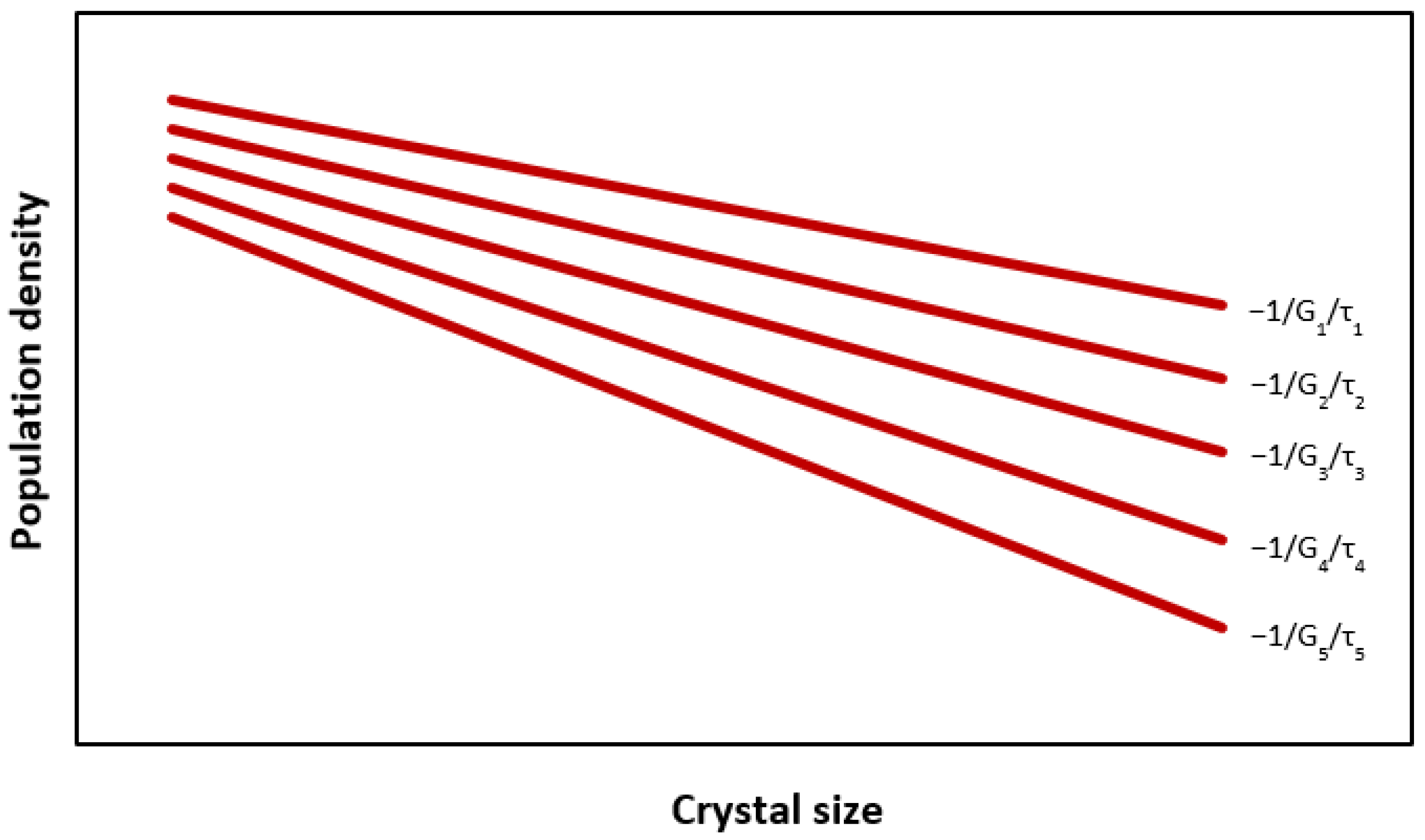
Figure 1. Population density plot for an experimental series of residence times.
Chemengineering 09 00097 g001
Figure 2. Variation of crystal growth rate as a function of residence time.
Chemengineering 09 00097 g002
Figure 3. Crystallization unit flow sheet.
Chemengineering 09 00097 g003
Figure 4. The simulation software layout.
Chemengineering 09 00097 g004
Figure 5. Inflow-outflow rate of various components/entities in the crystallizer.
Chemengineering 09 00097 g005
Figure 6. Variation of crystal production rate and crystallizer efficiency with respect to evaporator outlet pressure for saturated effluent.
Chemengineering 09 00097 g006
Figure 7. Effect of the solution mass fraction at the evaporator outlet on the crystal (anhydrous) flow rate and crystallization efficiency.
Chemengineering 09 00097 g007
Figure 8. Effect of the expansion valve outlet pressure and the number of solvate molecules on the flow rate of crystals, non-solvated crystals, and solvent vapors at the valve outlet.
Chemengineering 09 00097 g008
Figure 9. Variation of the flow rate of crystals and non-solvated crystals as a function of crystallizer pressure during expansion and cooling.
Chemengineering 09 00097 g009
Figure 10. Variation of the overflow solution and soluble solids flow rate as a function of crystallizer pressure.
Chemengineering 09 00097 g010
Figure 11. Effect of crystallizer temperature on crystal flow rate.
Chemengineering 09 00097 g011
Figure 12. Variation of magma density and crystallizer volume as a function of its recirculation ratio.
Chemengineering 09 00097 g012
Figure 13. Effect of crystallizer recirculation ratio on crystal growth rate.
Chemengineering 09 00097 g013
Figure 14. Effect of the number of solvate molecules on the outflow rate of the crystalline product.
Chemengineering 09 00097 g014
Figure 15. Effect of the number of solvate molecules on the flow rate of solution and soluble solids in the overflow.
Chemengineering 09 00097 g015
Figure 16. Comparative illustration of solvent vapor flow rate in individual equipment components.
Chemengineering 09 00097 g016
Figure 17. Illustration of solution mass fraction and corresponding saturation mass fraction in individual equipment elements.
Chemengineering 09 00097 g017
Figure 18. Illustration of the unit’s thermal loads (values expressed in kW).
Chemengineering 09 00097 g018
Figure 19. Illustration of the volume of the various entities within the crystallizer.
Chemengineering 09 00097 g019
Figure 20. Illustration of the mass of the various entities within the crystallizer.
Chemengineering 09 00097 g020
Figure 21. Effect of crystal diameter on residence time and crystallizer volume.
Chemengineering 09 00097 g021
Figure 22. Variation of magma density as a function of the crystallizer recycle ratio.
Chemengineering 09 00097 g022
Table 1. Mathematical model of the crystallization unit.
EquationNo
Feed
F i s s = F i   x i (1)
F i s l = F i   1 x i (2)
Q i = F i ρ i = F i s l ρ w + F i s s ρ s (3)
X i = x i 1 x i = F i s s F i s l (4)
Unit mixer
F i + F r c = F m (5)
F i   x i + F r c   x r c = F m   x m (6)
F i   C p i   T i + F r c   C p r c   T r c = F m   C p m x   T m (7)
F m s s = F m   x m (8)
F m s l = F m   1 x m (9)
Q m = F m ρ m = F m s s ρ s + F m s l ρ w (10)
X m = x m 1 x m = F m s s F m s l (11)
2-effect forward feed evaporator
T e 1 b = T e 1 + b p r e 1 (12)
T e 2 b = T e 2 + b p r e 2 (13)
F m = F L 1 + F V 1 (14)
F m   x m = F L 1   x e 1 (15)
Q e 1 = F m   C p m x T e 1 b T p h + F V 1   Δ H T e 1 (16)
Q e 1 = m s   Δ H T s (17)
Q e 1 = U e 1 1000   A e 1   T s T e 1 b (18)
F L 1 = F L 2 + F v 2 (19)
F L 1   x e 1 = F L 2   x e 2 (20)
Q e 2 = F L 1   C p e 1   T e 2 b T e 1 b + F v 2   Δ H T e 2 (21)
Q e 2 = F V 1   Δ H T e 1 (22)
Q e 2 = U e 2 1000   A e 2   T e 1 T e 2 b (23)
F V t = F V 1 + F v 2 (24)
S E = F V t m s (25)
F e 1 s s = F L 1   x e 1 (26)
F e 1 s l = F L 1   1 x e 1 (27)
F e 2 s s = F L 2   x e 2 (28)
F e 2 s l = F L 2   1 x e 2 (29)
Q L 1 = F L 1 ρ e 1 = F e 1 s s ρ s + F e 1 s l ρ w (30)
Q V 1 = F V 1 ρ e 1 v (31)
Q L 2 = F L 2 ρ e 2 = F e 2 s s ρ s + F e 2 s l ρ w (32)
Q V 2 = F V 2 ρ e 2 v (33)
u e 1 m v = C v ρ e 1 ρ e 1 v ρ e 1 v 0.5 (34)
u e 2 m v = C v ρ e 2 ρ e 2 v ρ e 2 v 0.5 (35)
Q V 1 = u e 1 m v   A e 1 c s (36)
Q V 2 = u e 2 m v   A e 2 c s (37)
A e 1 c s = π 4 D e 1 c s 2 (38)
A e 2 c s = π 4 D e 2 c s 2 (39)
X e 1 = x e 1 1 x e 1 (40)
X e 2 = x e 2 1 x e 2 (41)
Evaporator preheater
Q p h = F m   C p m x   T p h T m (42)
Q p h = F p h   Δ H T e f (43)
Δ T L p h = T m T p h l n T e f T p h T e f T m (44)
Q p h = U p h 1000   A p h   Δ T L p h (45)
F e c = F V 2 F p h (46)
Evaporator condenser
Q e c = F e c   Δ H T e f (47)
Q e c = F w e c   C p w   T w o T w i (48)
Expansion valve
V e x p 1 % = Δ H c r   R c r   X e f X c s b + C p e f   T e f b T c b s   1 + X e f   1 X c s b   R c r 1 Δ H T c b   1 X c s b   R c r 1 Δ H c r   R c r   X c s b (49)
V e x p % = I F P e f > P c   A N D   T e f b > T c b s ,   M A X ( V e x p 1 % , 0 ) ,   0 (50)
V = F e f s l   V e x p % (51)
F c r e x p = I F V e x p % > 0   A N D   x s s t > 0 ,   M A X 0 ,   F e f s l   R c r   X e f X c s b   1 V e x p % 1 X c s b   R c 1 ,   0 (52)
F c r e x p = F c r a e x p   R c r (53)
F c r e x p = F c r a e x p + F e x p s l h (54)
F e f s l = F e x p s l + V + F e x p s l h (55)
F e f s s = F e x p s s + F c r a e x p (56)
F e x p = F e x p s l + F e x p s s = F L f V F c r e x p = F e x p s l 1 + X e x p (57)
Q c r e x p = F c r e x p ρ c r (58)
Q e x p s t = F e x p ρ e x p = F e x p s s ρ s + F e x p s l ρ w (59)
Q e x p V = V ρ c v (60)
X e x p = F e x p s s F e x p s l (61)
x e x p = X e x p 1 + X e x p = F e x p s s F e x p = F e x p s s F e x p s l + F e x p s s (62)
Cooling crystallizer
F c r a m a x = F m   x m (63)
F c r a = F e f s s + X c s   V F e f s l 1 + X c s + R c r   X f M   x c s + R c r   X c s   X f M   x c s 1 1 (64)
F c r = F c r a   R c r = F c r a   M W s + n   M W s l M W s (65)
F s l h = F c r F c r a = F c r a   R c r 1 = F c r   n   M W s l M W s + n   M W s l (66)
F f M = F c r   X f M (67)
F M s s = F f M   x f s (68)
F M s l = F f M   1 x f s = F f M F M s s (69)
F c r M f = F c r   1 + X f M (70)
F e f s l = F s l h + F M s l + V + F c o s l (71)
F c o s s = F c o s l   X c s (72)
F c o s t = F c o s l + F c o s s (73)
F c o s z = f r c o   F c o s t (74)
F c o f = 1 f r c o   F c o s t (75)
F r = R c   F c r (76)
F f l = F c o f + F r (77)
F c t i = F L f + F r (78)
F c i = F L f + F r V = F e x p + F c r e x p + F r = F c t i V (79)
F c L = F e x p + F r (80)
F e x p   x e x p + F r   x c s = F c L   x c L (81)
F c L s s = F c L   x c L (82)
F c L s l = F c L   1 x c L (83)
T c m = I F P c P e f ,   T e f b ,   T c b s (84)
F e x p   C p e x p   T c m + F c r e x p   C p s   T c m + F r   C p m s t   T c = F c L   C p i + F c r e x p   C p s T c L (85)
F c m o = F f l + F c r M f (86)
Q f l = F f l ρ m s t = F f l x c s ρ s + 1 x c s ρ w = Q r + Q c o f (87)
Q c o s z = F c o s z ρ m s t = F c o s z x c s ρ s + 1 x c s ρ w (88)
Q c o f = F c o f ρ m s t = F c o f x c s ρ s + 1 x c s ρ w (89)
Q r = F r ρ m s t = F r x c s ρ s + 1 x c s ρ w (90)
Q c L = F c L ρ c L = F c L x c L ρ s + 1 x c L ρ w (91)
Q c i = Q e x p s t + Q c r e x p + Q r (92)
Q c m o = F c o s t + F r + F f M ρ m s t + F c r ρ c r = F c o f + F c o s z + F r + F f M ρ m s t + F c r ρ c r (93)
Q c r = F c r ρ c r (94)
n c r = F c r a F c r a m a x (95)
Crystallizer condenser
Q c c = V   Δ H T c b (96)
Q c c = F w c c   C p w   T c b T w i (97)
Crystallizer cooling
H c m = F c L   C p c i + F c r e x p   C p s   T c L (98)
H c o = F c o s t   C p m s t   T c (99)
H c r M = F c r   C p s + F f M   C p m s t   T c (100)
H c r = F c r F c r e x p   Δ H c r (101)
Q c = H c m H c r M H c o + H c r (102)
Cooling with water
Δ T L w c = T c L T w o T c T w i l n T c L T w o T c T w i (103)
Q c = U w c   A w c   Δ T L w c (104)
Q c m a = Q c A w c < 0.2 (105)
Cooling with a refrigeration cycle
Q c = Q e H P c = F r c   Δ H r c C p r c   T H P c c T H P e c (106)
Q c H P c = F r c   Δ H r c T H P c c + 273 T H P e c + 273 C p r c   T H P c c T H P e c (107)
E c m c = R r c   Δ H r c   T H P c c T H P e c T H P e c + 273 (108)
C O P c = Q e H P c E c c = T H P e c + 273 T H P c c T H P e c C p r c Δ H r c   T H P e c + 273 (109)
Δ T L e r c = T c L T H P e c T c T H P e c l n T c L T H P e c T c T H P e c = T c L T c l n T c L T H P e c T c T H P e c (110)
Q e H P c = U r s c   A H P e c   Δ T L e r c (111)
Δ T L c r c = T H P c c T w i T H P c c T w 2 o l n T H P c c T w i T H P c c T w 2 o = T w 2 o T w i l n T H P c c T w i T H P c c T w 2 o (112)
Q c H P c = U r w c   A H P c c   Δ T L c r c (113)
Crystallizer content
m c c r = F c r   τ c = M T   Q c m o   τ c (114)
m c s t = F c o s z + F c o f + F f M + F r   τ c = m ¯ m s t   Q c m o   τ c (115)
m m g = m c s t + m c c r = ρ m g   Q c m o   τ c = ρ m g   V m g (116)
m c s s = F c o s z + F c o f + F f M + F r   x c s   τ c = m ¯ s m s s   Q c m o   τ c (117)
m c s l = F c o s z + F c o f + F f M + F r   1 x c s   τ c = m ¯ s m s l   Q c m o   τ c (118)
V m g = Q c m o   τ c (119)
V c c r = Q c r   τ c = v f c   Q c m o   τ c = m c c r ρ c r (120)
V c s t = V m g V c c r = ε m g   Q c m o   τ c = m c s t ρ m s t (121)
V c s s = F c m o F c r   x c s ρ s   τ c = V ¯ s m s s   Q c m o   τ c = m c s s ρ s (122)
V c s l = F c m o F c r   1 x c s ρ w   τ c = V ¯ s m s l   Q c m o   τ c = m c s l ρ w (123)
Crystallization kinetics
G r e f = a G   τ + b G (124)
G = G r e f   M T M T r e f 1 j i + 3 (125)
L d = 3   G   τ (126)
B o = 2 9   F c r k v   ρ c r   V ¯ s m s l + V ¯ s m s s   L d 3 (127)
N c r = B o   V c s t (128)
B o = n o   G (129)
n c r m c r = 1 6   k v   ρ c r   G   τ 3 = 9 2   k v   ρ c r   L d 3 (130)
M T = 6   k v   ρ c r   n o   G   τ 4 (131)
Crystallizer sizing
V c = f v   V m g = f v   F c r M T   τ (132)
D c m = 4   V c π   R H D 0.33 (133)
u c m v = C v   ρ m s t ρ c v ρ c v 0.5 (134)
Q e x p V = u c m v   A c v c s (135)
D c v = 2 A c v c s π 0.5 (136)
D c = m a x D c m ,   D c v (137)
L c = 4   V c π   D c 2 (138)
Crystallization parameters
m s / c = n   M W s l (139)
R c r = M W s + m s / c M W s (140)
Operating pressure
P s = 1 760 10 A a n t B a n t C a n t T s (141)
P e 1 = 1 760 10 A a n t B a n t C a n t T e 1 (142)
P e 2 = 1 760 10 A a n t B a n t C a n t T e 2 (143)
P c = 1 760 10 A a n t B a n t C a n t T c b s (144)
Overall heat transfer coefficient
U p h = U e o 1 + a U   x m b U (145)
U e 1 = U e o 1 + a U   x e 1 b U (146)
U e 2 = U e o 1 + a U   x e 2 b U (147)
U c w = U c o w 1 + a U   x c s b U   (148)
U c r = U c o r 1 + a U   x c s b U   (149)
Solubility
X i s = a C T T i 2 + b C T T i + c C T / 0.1 / 1000 (150)
X r c s = a C T T r c 2 + b C T T r c + c C T / 0.1 / 1000 (151)
X m s = a C T T m 2 + b C T T m + c C T / 0.1 / 1000 (152)
X c s = X f s = a C T T c 2 + b C T T c + c C T / 0.1 / 1000 (153)
X c s b = a C T   T c b s 2 + b C T   T c b s + c C T / 0.1 / 1000 (154)
X c L s = a C T   T c L 2 + b C T     T c L + c C T / 0.1 / 1000 (155)
x i s = X i s 1 + X i s (156)
x r c s = X r c s 1 + X r c s (157)
x m s = X m s 1 + X m s (158)
x c s = x f s = X c s 1 + X c s = X f s 1 + X f s (159)
x c s b = X c s b 1 + X c s b (160)
x c L s = X c L s 1 + X c L s (161)
Solubility at boiling temperature of solution
x e 1 s = X e 1 s 1 + X e 1 s (162)
b p r e 1 s = a b p r   x e 1 s 2 + b b p r   x e 1 s (163)
T e 1 s b = T e 1 + b p r e 1 s (164)
X e 1 s = a C T   T e 1 s b 2 + b C T   T e 1 s b + c C T / 0.1 / 1000 (165)
x e 2 s = X e 2 s 1 + X e 2 s (166)
b p r e 2 s = a b p r   x e 2 s 2 + b b p r   x e 2 s (167)
T e 2 s b = T e 2 + b p r e 2 s (168)
X e 2 s = a C T   T e 2 s b 2 + b C T   T e 2 s b + c C T / 0.1 / 1000 (169)
Moisture content
X f M = M f 1 M f = M f % 100 M f % (170)
Thermophysical properties
Specific heat capacity
c p i = x i   C p s + 1 x i   C p w (171)
c p r c = x r c   C p s + 1 x r c   C p w (172)
C p m x = x m C p s + 1 x m C p w (173)
C p e 1 = x e 1   C p s + 1 x e 1   C p w (174)
C p e 2 = x e 2   C p s + 1 x e 2   C p w (175)
C p e x p = x e x p   C p s + 1 x e x p   C p w (176)
C p c i = x c L   C p s + 1 x c L   C p w (177)
Latent heat of vaporization
Δ H T s = a w + b w   T s + c w   T s 2 (178)
Δ H T e 1 = a w + b w   T e 1 + c w   T e 1 2 (179)
Δ H T e 2 = a w + b w   T e 2 + c w   T e 2 2 (180)
Δ H T c b = a w + b w   T c b s + c w   T c b s 2 (181)
Boiling point rise
b p r e 1 = a b p r   x e 1 2 + b b p r   x e 1 (182)
b p r e 2 = a b p r   x e 2 2 + b b p r   x e 2 (183)
Solution—vapor density
ρ i = x i ρ s + 1 x i ρ w 1 = F i Q i (184)
ρ r c = x r c ρ s + 1 x r c ρ w 1 = F r c Q r c (185)
ρ m x = x m ρ s + 1 x m ρ w 1 = F m Q m (186)
ρ e 1 = x e 1 ρ s + 1 x e 1 ρ w 1 = F L 1 Q L 1 (187)
ρ e 2 = x e 2 ρ s + 1 x e 2 ρ w 1 = F L 2 Q L 2 (188)
ρ e x p = x e x p ρ s + 1 x e x p ρ w 1 = F e x p Q e x p s t (189)
ρ c L = x c L ρ s + 1 x c L ρ w 1 = F c L Q c L (190)
ρ e 1 v = 101,325   P e 1   M W s l R g   T e 1 + 273 (191)
ρ e 2 v = 101,325   P e 2   M W s l R g   T e 2 + 273 (192)
ρ c v = 101,325   P c   M W s l R g   T c + 273 (193)
Statistical analysis of product crystals
n = n o   e x p L G τ (194)
N L = n o   G   τ   1 e x p L G τ (195)
N T = n o   G   τ (196)
L L = n o   G   τ G   τ   1 e x p L G   τ L   e x p L G   τ (197)
L T = n o   G   τ 2 (198)
A L = 2   k a   n o   G   τ G   τ 2 G   τ 2 + G   τ   L + L 2 2 e x p L G   τ (199)
A T = 2   k a   n o   G   τ 3 (200)
M L = 6   k v   ρ c r   n o   G   τ G   τ 3 G   τ 3 + G   τ 2 L + G   τ   L 2 2 + L 3 6   e x p L G   τ (201)
X L = L G τ (202)
N L N T = 1 e x p X L (203)
L L L T = 1 1 + X L   e x p X L (204)
A L A T = 1 1 + X L + X L 2 2   e x p X L (205)
M L M T = 1 1 + X L + X L 2 2 + X L 3 6   e x p X L (206)
d N L / N T d X L = e x p X L (207)
d L L / L T d X L = X L e x p X L (208)
d A L / A T d X L = X L 2 2 e x p X L (209)
d M L / M T d X L = X L 3 6 e x p X L (210)
Crystallization unit efficiency
f c h = Q e 1 n h   Δ H f (211)
f c e = E c m c n e   Δ H f (212)
f c   = f c h + f c e (213)
n c r = F c r a F c r a m a x (214)
Table 2. Design specifications, technical data, and design and trial-and-error variables of the unit.
Process Specifications
Feed pressurePi (atm)1.0
Feed solution flow rateFi (kg solution/s)8.4
Feed solution mass fractionxi (kg soluble solids/kg solution)0.08
Feed solution temperatureTi (°C)24.0
Heating steam temperatureTs (°C)125
Crystalline product moisture content (wet basis)Mc (kg solution/kg crystalline slurry)0.30
Dominant size of crystalline productLd (μm)850
Solution mass fraction at evaporator final effect outletxe2 (kg soluble solids/kg solution)0.38
Feed outlet temperature from preheaterTph (°C)75
Cooling water inlet temperatureTwi (°C)15
Design variables
First effect evaporator temperatureTe1 (°C)100
Second effect evaporator temperatureTe2 (°C)82
Crystallizer temperatureTc (°C)0
Filter working temperatureTf (°C)0
Crystallizer pressurePc (atm)0.10
Ratio of recycling solution flow rate to crystalline product flow rate (crystallizer recycle)Rc (-)2.30
Fraction overflow flow rate from the settling zonefroc (-)0.00
Cooling water outlet temperature for crystallizerTwo (°C)20
Cooling water outlet temperature for coolersTw2o (°C)35
Crystallizer heat pump evaporator temperatureTHPec (°C)−3
Crystallizer heat pump condenser temperatureTHPcc (°C)40
Trial-and-error variable
Solution mass fraction at evaporator first effect outletxe1 (kg soluble solids/kg solution)0.132
Technical data
Solubility—temperature constantaCT (-)0.0043
Solubility—temperature constantbCT (-)0.1665
Solubility—temperature constantcCT (-)15.117
Heat of vaporization—temperature constant for waterAw (-)2491.5
Heat of vaporization—temperature constant for waterBw (-)−2.048
Heat of vaporization—temperature constant for waterCw (-)−0.0032
Antoine constant for waterAant (-)8.07131
Antoine constant for waterBant (-)1730.63
Antoine constant for waterCant (-)233.426
Overall heat transfer coefficient constant for solutionUeo (W/m2/°C)1000
Overall heat transfer coefficient constant for solutionaU (-)4
Overall heat transfer coefficient constant for solutionbU (-)1.2
Overall heat transfer coefficient for crystallizer heat pump condenserUrco (W/m2/°C)700
Overall heat transfer coefficient constant for water coolingUwco (W/m2/°C)500
Anhydrous solid molecular weightMWs (kg/mol)0.125
Solvent molecular weightMWsl (kg/mol)0.018
Boiling point elevation constantabpr (-)15
Boiling point elevation constantbbpr (-)10
Specific heat of crystallizationΔHcr (kJ/kg crystals)30
Latent heat of vaporization of heat pump fluidΔHrc (kJ/kg)1250
Liquid solvent heat capacityCpw (kJ/kg/°C)4.18
Vapor solvent heat capacityCpv (kJ/kg/°C)1.88
Solute heat capacityCps (kJ/kg/°C)2.4
Crystallizer heat pump fluid heat capacityCprc (kJ/kg/°C)1.20
Solvent densityρw (kg/m3)1000
Crystal densityρs (kg/m3)1850
Fuel calorific valueΔHf (kJ/kg)50,000
Thermal efficiencynh (-)0.92
Electrical efficiencyne (-)0.63
Crystal growth rate—residence time constanta (-)−2.48 × 10⁻¹²
Crystal growth rate—residence time constantb (-)7.22 × 10⁻⁹
Reference magma densityMTref (kg/m3)280
Exponent of the crystallization kinetic equationi (-)3.5
Exponent of the crystallization kinetic equationj (-)0
Universal ideal gas constantRg (J/mol/°C)8.314
Constant for maximum allowable vapor velocityCv (m/s)0.0244
Vessel increase factorfv (-)1.4
Height-to-diameter vessel ratioRHD (-)1.54
Crystal volume shape factorkv (-)0.627
Number of hydrate molecules per solid moleculen (-)3.0
Table 3. Process variables of the crystallization unit.
Process Variables
Preheater heat dutyQph (kW)1729.7
Evaporator first effect outlet solution flow rateFL1 (kg solution/s)5.110
Evaporator first effect vapor flow rateFV1 (kg solvent/s)3.290
Evaporator second effect outlet solution flow rateFL2 (kg solution/s)1.768
Evaporator second effect vapor flow rateFV2 (kg solvent/s)3.342
Evaporator first effect heat dutyQe1 (kW)8319.3
Evaporator second effect heat dutyQe2 (kW)7418.0
Heating steam flow ratems (kg heating steam/s)3.807
Evaporator condenser heat dutyQce (kW)5962.7
Flow rate of solvent vaporized due to expansion in the crystallizerV (kg solvent/s)0.116
Crystals flow rate at the expansion valveFcrexp (kg crystals/s)0.596
Anhydrous crystals flow rate at the expansion valveFcraexp (kg anhydrous crystals/s)0.416
Magma densityMT (kg crystals/m3 magma)260.7
Theoretical maximum anhydrous crystal flow rateFcramax (kg crystals/s)0.672
Crystals (anhydrous) outlet flow rateFcra (kg crystals (anhydrous)/s)0.560
Crystals (hydrated) outlet flow rateFcr (kg crystals/s)0.802
Hydrated solvent flow rate exiting crystallizerFslh (kg solvent/s)0.242
Moisture flow rate exiting crystallizer (including its filter)FfM (kg moisture/s)0.344
Moisture-soluble solids flow rate exiting the crystallizer (including its filter)FMss (kg soluble solids/s)0.045
Moisture solvent flow rate exiting the crystallizer (including its filter)FMsl (kg solvent/s)0.299
Outlet flow rate of crystalline product, including its moisture, at filter outletFcrMf (kg crystalline product/s)1.146
Solution flow rate exiting crystallizer as overflowFcost (kg solution/s)0.506
Recycling solution flow rateFr (kg solution/s)1.846
Filtrate flow rateFfl (kg solution/s)2.352
Crystallizer total inlet solution flow rate prior to expansionFcti (kg solution/s)3.614
Crystallizer total inlet solution and crystal flow rate following expansion (excluding vapor flow rate)Fci (kg solution-magma/s)3.498
Crystallizer total inlet solution flow rate (solution flow rate at crystallizer mixer)FcL (kg solution/s)2.902
Feed solution/magma temperature at expansion valve outlet (crystallizer mixer inlet)Tcm (°C)46.1
Solution/magma temperature at crystallizer mixer outletTLc (°C)19.6
Outlet magma flow rate from the crystallizer (feed to its filter)Fcmo (kg magma/s)3.498
Outlet magma volumetric flow rate from the crystallizerQcmo (m3 magma/s)3.078 × 10−3
Crystallization recovery (efficiency)ncr (-)0.834
Solution/magma enthalpy at crystallizer mixer outletHcm (kW)248.7
Enthalpy of solution overflows crystallizerHco (kW)0.0
Crystalline product enthalpyHcrM (kW)0.0
Heat of crystallizationHcr (kW)6.2
Crystallizer heat pump evaporator heat dutyQeHPc (kW)254.9
Heat pump fluid flow rateFrHPc (kg fluid/s)0.213
Crystallizer heat pump condenser heat dutyQcHPc (kW)297.3
Heat pump compressor electrical powerEcc (kW)42.3
Product retention timeτp (h)16.98
Crystal growth rateG (m/s)4.64 × 10−9
Crystallizer volumeVc (m3)263.4
Table 4. Representation of the individual components’ flow rate in the equipment elements of the crystallization unit.
Solvent (kg/s)Soluble Solids (kg/s)Crystals (kg/s)Solvent Hydrated (kg/s)Vapor (kg/s)
Feed17.7280.672
Evaporator first effect24.4380.672 3.290
Evaporator second effect31.0960.672 3.342
Expansion valve40.8090.2590.5920.1790.108
Crystallizer outlet50.7460.1130.8010.242
Disclaimer/Publisher’s Note: The statements, opinions and data contained in all publications are solely those of the individual author(s) and contributor(s) and not of MDPI and/or the editor(s). MDPI and/or the editor(s) disclaim responsibility for any injury to people or property resulting from any ideas, methods, instructions or products referred to in the content.