Article

Graphite/β-PbO2 Composite Inert Anode Synthesis Using Electrochemical Methods

Chemical Engineering Department, Faculty of Engineering, Universitas Sriwijaya, Indralaya 30622, Indonesia
*
Author to whom correspondence should be addressed.
ChemEngineering 2023, 7(2), 20; https://doi.org/10.3390/chemengineering7020020
Submission received: 15 September 2022 / Revised: 10 October 2022 / Accepted: 28 January 2023 / Published: 6 March 2023

Abstract

:
The anode material is one of the determining factors for the success of the electrowinning process. This study aims to coat the graphite substrate with β-PbO2 to produce an inert graphite/β-PbO2 composite material with low cost and good quality. The graphite/β-PbO2 synthesis is expected to be used as an anode for inert composites for electrowinning processes. The β-PbO2 deposition layer was prepared on the surface of the graphite substrate by an electrodeposition process using a sulfuric acid electrolyte. The effect of electrolyte concentration and voltage on graphite/β-PbO2 synthesis was investigated using a potentiodynamic polarization test through Tafel analysis. Experimental data have shown that there is an increase in the current density value at the beginning of the process and then a decrease due to passivation; this is due to anodic polarization in the graphite/β-PbO2 synthesis process. Suitable conditions can effectively increase the rate of formation of β-PbO2. The results of scanning electron microscopy with energy-dispersive X-ray spectroscopic analysis of the formed crystal structure showed that the β-PbO2 deposition layer obtained had a well-formed tetragonal structure at a voltage of 9 V.

1. Introduction

The success factor of the electrowinning process lies in the role of the inert anode composite. Composite inert anodes have adjustable strength, lighter weight, stability and corrosion resistance in acidic media, good electroconductivity, and relatively long service life [1,2,3]. The constituent materials of an inert anode consist of cermets (a combination of two materials, namely metal and ceramic), metal oxides (ceramic), and metal. An inert electrode is an electrode that only functions as a source or reservoir of electrons or acts as an electrocatalyst [4]. Inert materials such as Pb and Pb-based alloys, PbO2, and group metal oxides [5,6,7]. Lead dioxide material as anode in the electrowinning process continues to develop because it has good resistance to sulfuric acid media, electrochemical oxidation ability to reduce organic contaminants through oxygen evolution reactions, good conductivity, and is economical [3,8,9].
The electrodeposition technique for the synthesis of composite materials can be optimized by the properties of the substrate, namely high surface area, good electrical conductivity, and high adhesion to PbO2 [10,11]. Various studies on the development of substrates for PbO2 deposition are Titanium [12,13,14,15], Aluminum [16,17], Tin [18], Copper [19], Platinum [20], stainless steel [21], and graphite [22]. Titanium is generally used as a substrate for PbO2 deposition, but titanium can react with oxygen, and the price of titanium is still relatively high [6,7,23]. Judging from the availability, stability, low density, good current collecting properties, and economical properties, in this study, graphite was chosen as a substrate for PbO2 deposition [9,22].
PbO2 is divided into two types, namely α-PbO2 in the orthorhombic form and β-PbO2 in the tetragonal form. β-PbO2 has advantages in electrocatalytic activity for oxygen evolution due to its higher porosity and larger active surface area. For the process of oxygen evolution reaction with an electrochemical mechanism, β-PbO2 is preferred [8,24].
Graphite as a substrate for the deposition of PbO2 through the anodization process, this study compared the electrochemical performance of graphite and PbO2 coated on a graphite substrate through acid, alkaline, and buffer electrolytes [22]. The research on the synthesis of Ti/PbO2 uses a titanium substrate with the addition of CeO2 and graphite powder; then, the resulting material is analyzed [14]. The Al/Pb/α-PbO2 study was carried out in two stages. The first step is the synthesis of the Al/Pb substrate. The second stage used Al/Pb as an anode for the synthesis of Al/Pb/α-PbO2. This research takes a long time and has relatively high costs because it goes through a two-stage process [5].
This study aims to develop the basic concept of β-PbO2 on a graphite substrate to produce an inert anode of graphite/β-PbO2 composite. The main idea of this research is to study the effect of sulfuric acid electrolyte concentration and voltage on the graphite/β-PbO2 synthesis process. Variation of sulfuric acid concentration and voltage aims to increase the value of current density so that the amount of β-PbO2 deposited on the substrate increases. Flexible graphite sheets and Pb plates are used as electrodes. The effect of electrolyte concentration and voltage on graphite/β-PbO2 synthesis were tested for potentiodynamic polarization test based on Tafel analysis, phase structure and surface microstructure of graphite substrate and β-PbO2 layer were tested by scanning electron microscopy with energy-dispersive X-ray spectroscopy. The results of this study are expected to provide an alternative theory for the synthesis of graphite/β-PbO2 composite inert anode materials.

2. Materials and Methods

2.1. Preparation

A Pb plate (TB; Tin Bangka) with a purity of 99.9% was used as anode (0.9 mm × 0.5 mm × 2 mm), and a flexible graphite sheet (PT; Fikri Jaya Sejati, Jakarta, Indonesia) was used as a cathode, with dimensions of 0.9 mm × 0.5 mm × 3 mm.
The anode preparation was started with the Pb plate being sanded with sandpaper to remove the oxide layer that forms on its surface, washed with acetone (Merck & Co, Darmstadt, Germany), rinsed with distilled water (Dirasonita, Palembang, Indonesia) for 10 min, picked in 1 mol/1 L NaOH (Merck & Co, Darmstadt, Germany) at 60 °C and rinsed with ethanol (Merck & Co, Darmstadt, Germany). The cathode preparation stage involved washing with alkaline 40 g/L NaOH (Merck & Co, Darmstadt, Germany) (60 °C, 30 min), rinsing with distilled water (Dirasonita, Palembang, Indonesia), and pickling in 600 mL/L H3PO4 (Merck & Co, Darmstadt, Germany) (85%) and 20 mL/L HNO3 (Merck & Co, Darmstadt, Germany) for 90 s [25].

2.2. Material Synthesis

The sulfuric acid electrolyte solution (Merck & Co, Darmstadt, Germany) was used in various concentrations: 1 M, 2 M, 3 M, 4 M, and 5 M. Voltage variations were 6 V, 9 V, and 12 V. A much as 1000 mL of the sulfuric acid solution was added into the electrolysis bath, for the anode and cathode, connected to the voltage regulator, and the voltage adjusted according to the specified variable. The cathode was weighed every 15 min for a total processing time of 60 min. After the process was completed, the cathode was rinsed with distilled water and dried using a vacuum furnace. Lastly, the cathode was weighed.

2.3. Material Characteristics

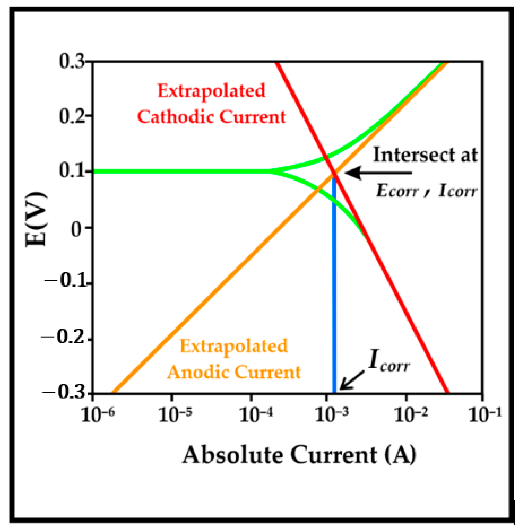
2.3.1. Potentiodynamic Polarization

The electrodeposited material was tested for Tafel polarization using the Gamry Potentiostat Reference 600 (Philadelphia, PA, USA). In the polarization test, the sample was mounted using clarocit powder and clarocit liquid at a ratio of 2:1 such that only the surface of the electroplated results would be exposed to the solution. An electrical connection was provided with a copper cable on the plate inside the mounting.
The samples were tested for potentiodynamic polarization by means of the Tafel polarization method using ASTM G3, G5, and G59 test standards. The solution used was 12.5% NaOH at a potential range of (−)250 mV to (+)250 mV and a scan rate of 1 mV/s from the open circuit potential. The test used three-electrode cells: the sample was a working electrode, the counter electrode was a graphite rod, and the reference electrode was Ag/AgCl. The actual potential of the half-cell was +0.197 V vs. SHE. The Tafel polarization diagram was obtained from Gamry Echem Analysis software (Philadelphia, PA, USA). Tafel polarization is helpful for determining corrosion current density (Icorr) and corrosion potential (Ecorr) parameters. The corrosion current (Icorr) cannot be determined directly, but its value can be determined by extrapolating the curve log current versus the corrosion potential Ecorr. Ecorr is defined as the potential at which the total velocities of all anodic reactions are equal to the total velocities of all cathodic reactions. The intersection of the extrapolated curves will produce a point with coordinates (Icorr, Ecorr), as shown in Figure 1.
The corrosion current in the potentiodynamic polarization test was used to determine the corrosion rate (CR) with the equation [26]:
C R   = i corr A w zF ρ
icorr is current density (μA/cm2), Aw is the atomic weight of the metal, z is valence or oxidation number, and F is Faraday’s constant (96,500 C/mol) and ρ is the density (g/cm2).

2.3.2. Scanning Electron Microscopy with Energy-Dispersive X-ray Spectroscopy

To review the topography and morphology and determine the elements contained in the sample, scanning electron microscopy with energy-dispersive X-ray spectroscopy analysis Hitachi Flexsem 1000, (Hitachi, Tokyo, Japan) was used. Scanning electron microscopy aims to observe the morphology and topography of the samples. Energy-dispersive X-ray spectroscopy is used to determine the elements contained in the sample. Energy-dispersive X-ray spectroscopy can be applied to small areas (dots), lines, and squares, as well as be used to determine the distribution of elements (mapping) in the sample. Observation of samples was conducted at magnifications of 200 times, 1000 times, and 5000 times.

3. Results

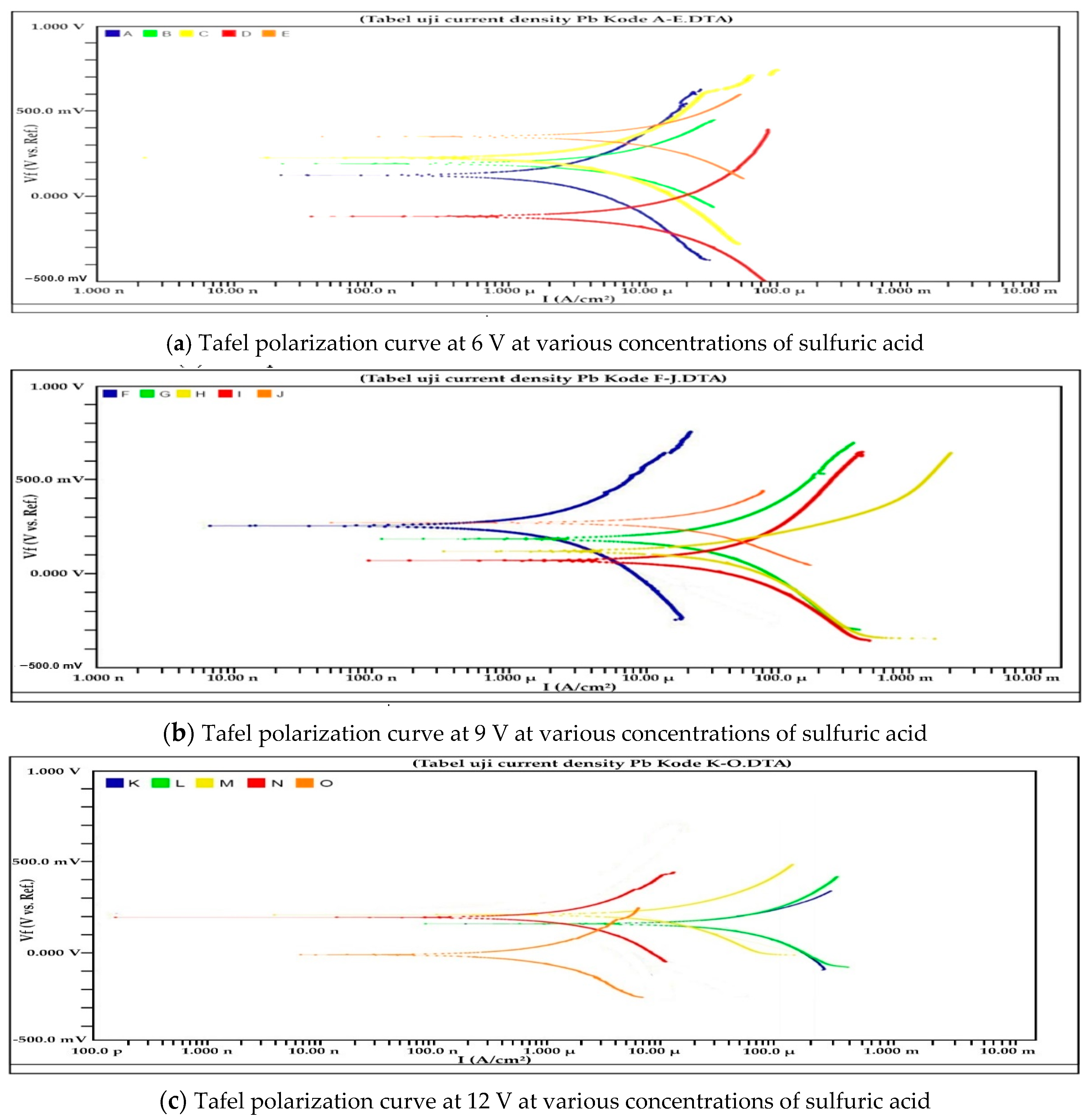
3.1. Potentiodynamic Polarization Test

Tafel polarization has two curve branches: the anodic curve (top of the curve) and the cathodic curve (bottom of the curve). The cathodic curve describes the phenomenon of the reduction reaction in the H2SO4 solution by removing several electrons from the metal, whereas the anodic curve describes the oxidation reaction in the metal with the loss of several electrons. The results of potential scanning in the range of ±250 mV against Ecorr in a corrosion system in H2SO4 solution at various voltages and concentrations are shown in Figure 2.
From Figure 2, the relationship between potential and corrosion current with variations in sulfuric acid concentration at voltages of 6 V, 9 V, and 12 V produced Ecorr, current density, and corrosion rate, which are shown in Table 1, Table 2 and Table 3.

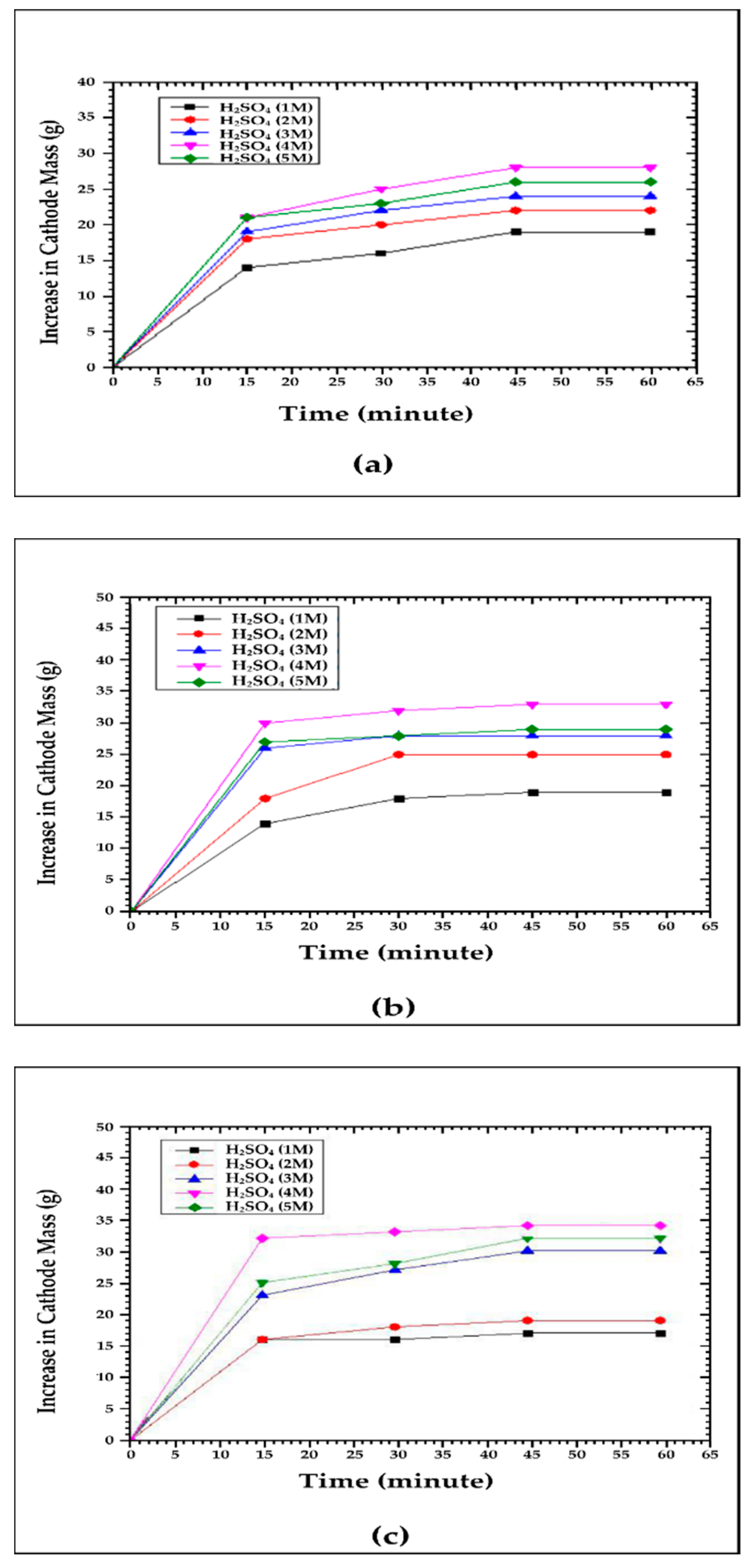
3.2. Effect of Voltage and Sulfuric Acid Concentration on Cathode Mass Increase

This study was conducted by varying the voltage (6 V, 9 V, and 12 V) and sulfuric acid concentrations (1 M, 2 M, 3 M, 4 M, and 5 M). The mass gain of the cathode was weighed every 15 min for 60 min and is displayed on Figure 3.

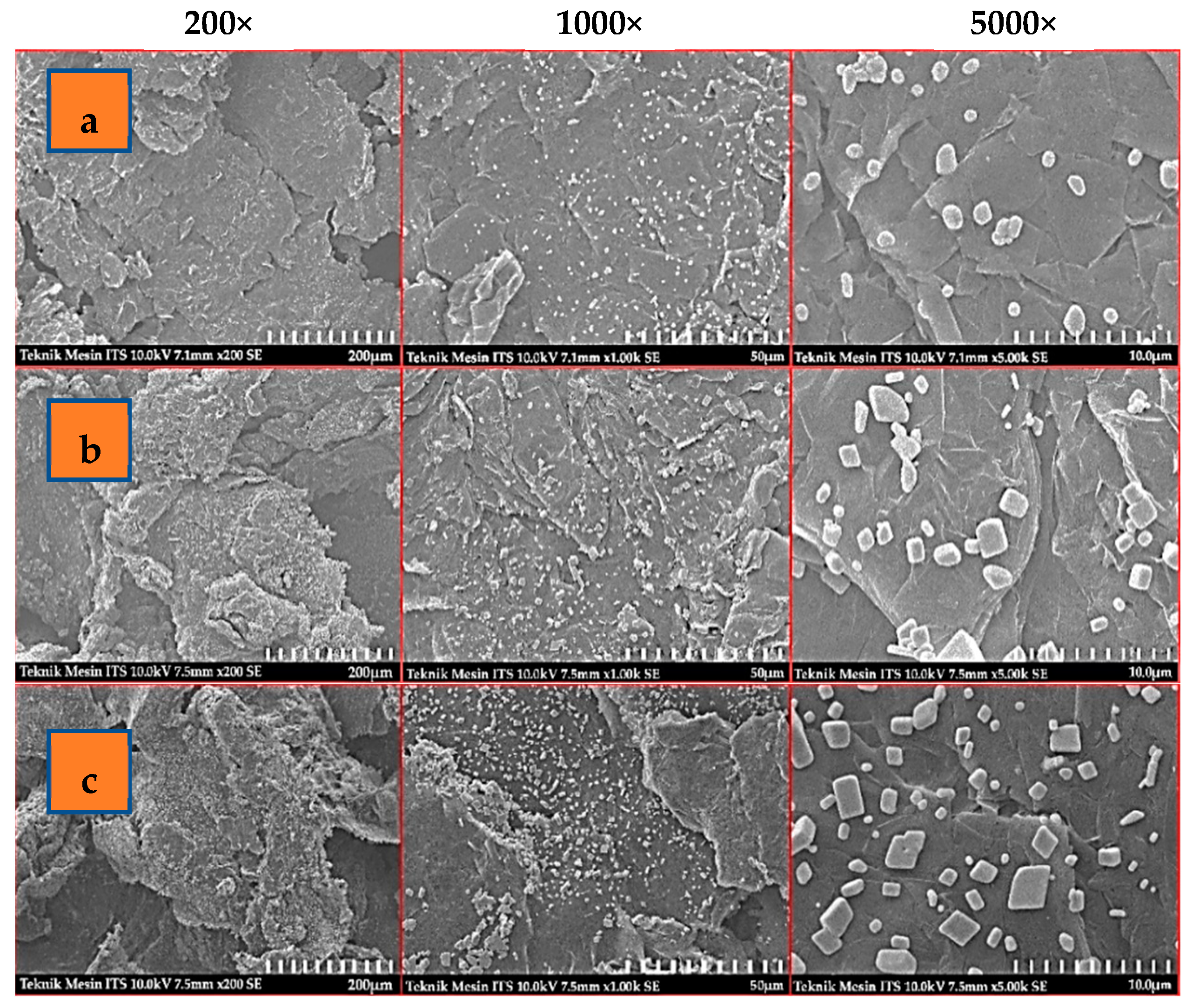
3.3. Scanning Electron Microscopy with Energy-Dispersive X-ray Spectroscopy

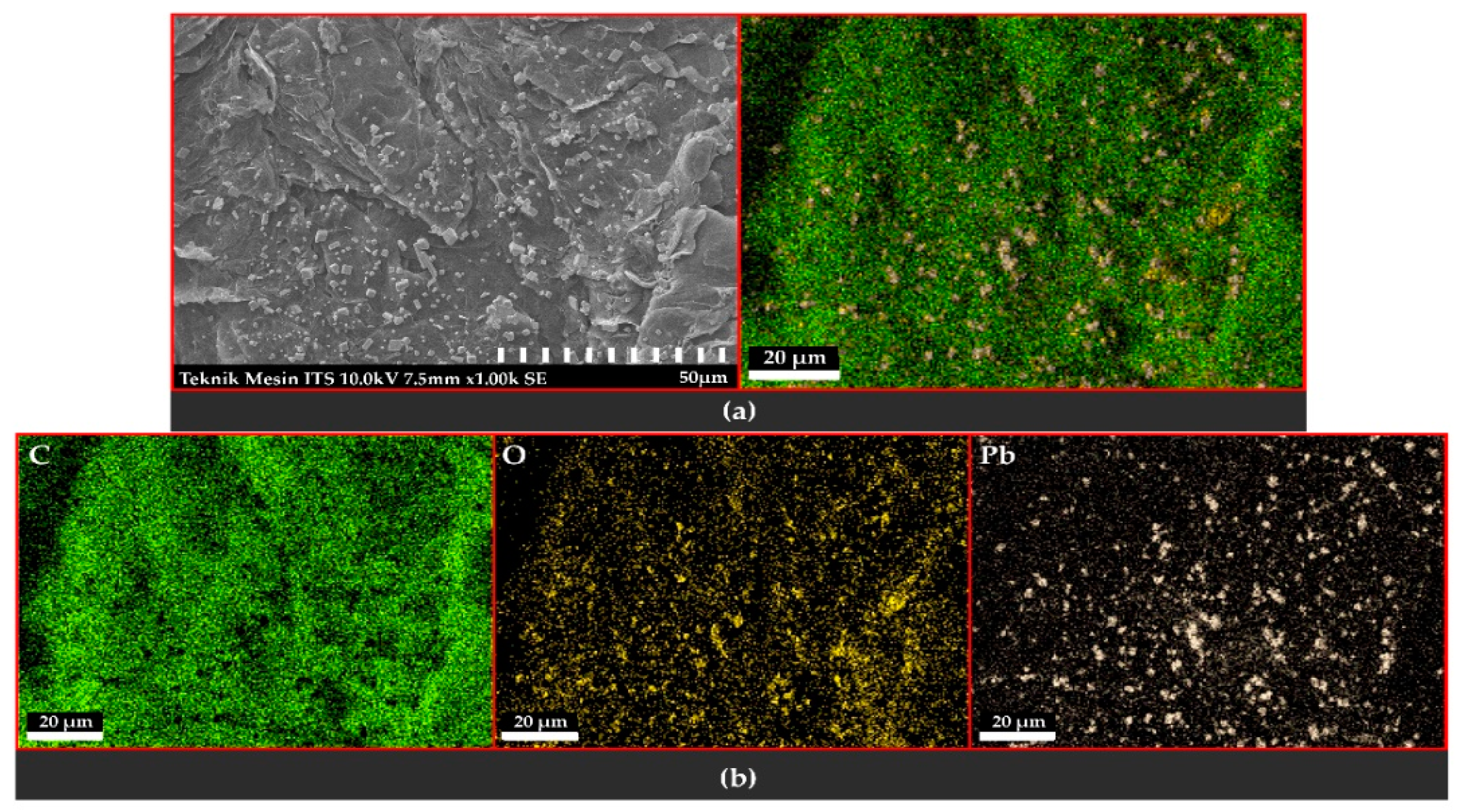
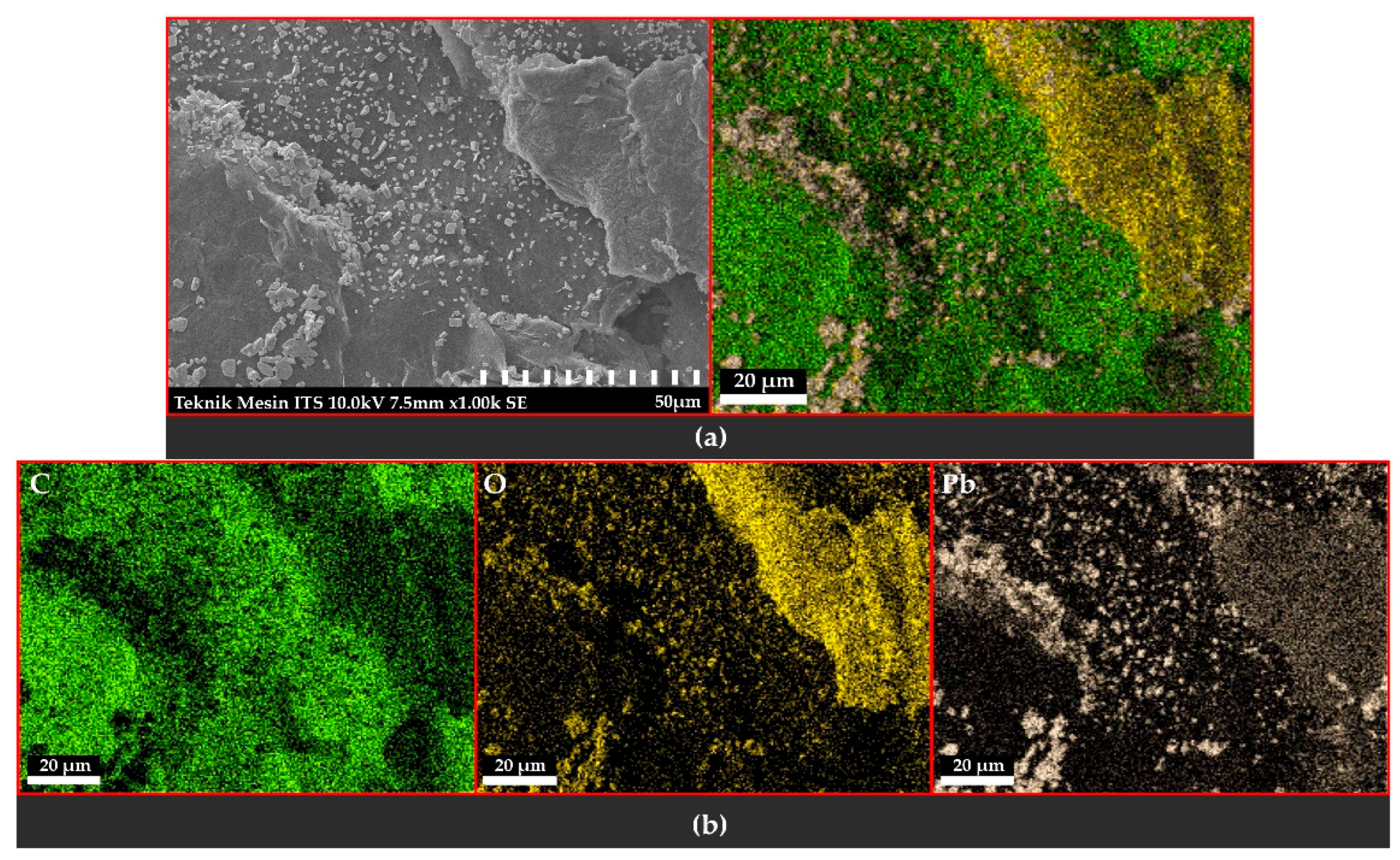
3.3.1. Observation of the Topography and Morphology of the Sample

Scanning electron microscopy analysis aims to observe topography and morphology, whereas energy-dispersive X-ray spectroscopy aims to determine the elements contained and the distribution of elements in a sample is displayed on Figure 4.

3.3.2. Distribution and Elemental Composition

Voltage of 6 V

Figure 5 shows the results of the distribution of elements in the 6 V sample variation. Elements C, O, and Pb were found. Element C comes from the use of the flexible graphite sheet as a cathode. The distribution of elements O and Pb on the surface was uneven but accumulated on one side of the surface.

Voltage of 9 V

Figure 6 shows the results of the distribution of elements in the 9 V sample variation. From the mapping image, the elements O and Pb were found. It appears that the elements were more evenly distributed on the surface, but there were parts where atomic vacancies could be observed caused by defects in the material.

Voltage of 12 V

Figure 7 shows the results of the distribution of the elements in the 12 V sample variation. From the mapping image, it was found that there was more thickening on several sides of the surface. The elements O and Pb were also found, but the distribution of these elements appeared uneven on the surface. The distribution of PbO2 was only found in the middle, namely, the surface, where there were no defects. The spread of element O looked lumpy on one side. Pb was more evenly distributed than element O but agglomerated in certain areas. This defect caused the distribution of the elements to be uneven on the material’s surface.

4. Discussion

4.1. Potentiodynamic Polarization

From Figure 2, it can be observed that anodic polarization occurred. In the potential range up to +250 mV, there was a potential shift in the positive direction. This indicated an active-to-passive transition. Anodic polarization increased the current density value, which was directly proportional to the increase in the corrosion rate. This means an increase in the quantity of electrodeposition results at the cathode. The current density value increased at the beginning of the process before subsequently decreasing; this phenomenon can be seen in Table 1, Table 2 and Table 3.
Table 1 and Table 2 showed the same tendency: the current density value continued to increase until the H2SO4 concentration was 4 M. The increase in current density was because the sulfuric acid was polar, so the conductivity was high. The number of lone pairs of electrons in the electrolyte solution indicated the degree of dissociation ability of the solution. The higher the number of lone pairs of electrons, the greater the charge generated. The amount of charge was also influenced by the concentration of the solution contained in the electrolyte compound. The higher the electrolyte concentration, the more ions were decomposed for them to better conduct the electric current [27,28]. The polarization curve for the variation with a 4 M sulfuric acid concentration in the sample shifted downwards to the right. At a voltage of 6 V, the optimum current density value was 6.03 μA/cm2, and the corrosion rate was 7.10 mpy, whereas at a voltage of 9 V, the current density value was 28.14 μA/cm2 and the corrosion rate was 33.08 mpy. At a voltage of 9 V, a higher current density value was produced, higher than that at 6 V. This was because, at a higher voltage, the electrons are more active. However, the 5 M electrolyte concentration showed a curve shifted up and to the left, the potential range under Eocp starting from −250 mV to the free corrosion potential (Eocp), displayed a reduction reaction, with a decrease in current density and corrosion rate.
Table 3 shows a slight difference from Table 1 and Table 2. In Table 3, the current density value in sample M (3 M) was 25.89 μA/cm2, and the corrosion rate was 30.44 mpy. In sample N (4 M), the current density value began to decrease.
The Pb anode was active so that Pb would dissolve in the electrolyte solution. The sulfuric acid used as an electrolyte solution acted as a strong oxidizing agent causing Pb to be oxidized to unstable Pb. Pb, originating from the anode surface, reacted with negative ions SO42− to form PbSO4. With reference to [29,30], the oxidation reaction occurred with Pb electrons at the anode surface and the sulfate ions in the electrolyte, producing PbSO4 (2) and the oxygen evolution reaction, namely the decomposition of water and liberation of oxygen (3).
Pb + SO 4 2 + 2 e   PbSO 4
2 H 2 O   4 H + + O 2 + 4 e
At the cathode, there was a reduction in Pb ions from the solution, which moved towards the cathode while receiving two electrons and settled into Pb atoms on the surface/coating the cathode. Then the Pb ions settled, and H2 ions entered the solution so that the charge was maintained in the solution. This process continued continuously, which could be observed in the form of gas bubbles and the changing color of the solution.
PbSO 4 + 2 H 2 O 2 e   PbO 2 +   H 2 SO 4 + 2 H +
The reaction between PbSO4 and H2O produced PbO2. The formation of this oxide layer made the layer passive with corrosion resistance.
The decrease in current density values in Table 1, Table 2 and Table 3 was due to the passivation process, namely, the loss of metal reactivity caused by ions from metal elements reacting with oxygen to form a protective oxide layer (passive film) on the surface of metal materials. Pb metal had a reasonably high electronegativity value, so it could quickly react with oxygen and form a thin oxide layer on the cathode surface.

4.2. Effect of Voltage and Sulfuric Acid Concentration on Cathode Mass Increase

Faraday’s Second Law explains that mass (W) is the result of the multiplication of e (equivalent mass), I (current, A), and t (time, second) inversely proportional to Faraday’s constant (96,500 Coulomb).
W = e   ×   I   ×   t F
One of the important electrical properties of solid materials is the process of transmitting electric current. Ohm’s law regarding current (I) and voltage (V) is formulated as follows
V = I × R
The electric current (I) is the amount of charge (q) that flows per unit of time (t). An electric current can occur due to the presence of an electron flow. Each electron has a charge of the same magnitude, and in the conducting wire, there is a flow of large number of electrons.
Sulfuric acid is a mineral acid that is highly corrosive, clear, and colorless and belongs to the class of strong acids. The dielectric constant is the ratio of electrical energy stored in a material if given a potential. This dielectric constant is closely related to the polarity of a substance. Sulfuric acid has a high dielectric constant, meaning that it has high polarity properties. The polarity of a compound occurs because the atoms of the element have a considerable difference in electronegativity. The existence of such a difference in electronegativity causes the bonded electron pair to be more attracted to one of the elements, forming a dipole. The presence of dipoles is what causes the compound to become polar. Polarity is expressed by the dipole moment (μ), which is the product of the multiplication of the charge (q) and the distance (r)
µ = q × r
When sulfuric acid has good polar properties, its conductivity is high. Free electron pairs are one of the factors in determining the type of electrolyte. The number of free electrons in the electrolyte solution signals the degree of dissociation ability of the solution. The higher the number of free electrons, the more charge is generated. The amount of charge is also influenced by the concentration of the solution present in the electrolyte compound.
Based on the equations above, variations in voltage and the high concentration of solutions cause the number of mass deposits at the cathode to increase. In Figure 3, the graph pattern is supposed to form a linear relationship for each variation in the voltage and concentration of the electrolyte. The resulting data show that at a concentration of 4 M for each voltage variation, the greatest mass gain was at the cathode. At a concentration of 5 M, there were increased bubbles in the electrodeposition process, the deposits formed at the cathode were accelerating, but the precipitate was not well attached and, therefore, melted back into the electrolyte solution; this caused the mass gain at the cathode to decrease at this concentration.
From Figure 3, it can be observed that the mass gain at the cathode experienced the same tendency at each variation in voltage. The cathode mass gains occurred rapidly during the first 15 min. After 30 min, the resulting mass gain began to slow and almost reach a stable level. There was a stable mass at time measurements from 45 min to 60 min due to the occurrence of passivation. Metal passivation is an event involving a loss of reactivity of metal reactions due to the presence of certain environmental conditions.

4.3. Scanning Electron Microscopy with Energy-Dispersive X-ray Spectroscopy

Figure 4 is the result of scanning electron microscopy analysis, which showed the topographical surface of the material resulting from the electrodeposition process with the optimum current density value for each voltage variation. Scanning electron microscopy analysis used three magnifications, namely 200×, 1000×, and 5000×.
Figure 4a with 1000× magnification presents the PbO2 material as not evenly distributed over the surface of the graphite substrate. The distribution is more dominant on some sides of the surface. The surface is uneven, and some parts have thickened. At 5000× magnification, an amorphous structure is formed.
In Figure 4b, with 1000× magnification, the surface appears smoother and flatter. There is a slight thickening on the underside of the image. The PbO2 material distribution was more even and more abundant than in Figure 4a. The image with 5000× magnification showed the formation of a tetragonal crystal structure.
In Figure 4c, with 1000× magnification, the surface is rough. Thickening in the form of a wave is found on many sides. The distribution of the material is uneven, only in the middle, whereas the thickened surface is almost non-existent. The thickening of the material was a crystal defect. This was influenced by the temperature produced during the process. The higher the temperature, the bigger the defect. The temperature of the process was affected by the voltage and electrolyte concentration. The high temperature caused the mass to increase at the cathode, and more crystal defects occurred. From Figure 4c, more and more crystal defects can be observed compared with Figure 4a,b.
The amorphous structure formed due to the high process temperature, followed by sudden cooling after the electrodeposition process, resulted in the formation of imperfect crystals. In addition to the amorphous structure, a crystal with a tetragonal structure was found with random distribution at the voltage variation of 9 V and 12 V. According to research by [24,29,30], this tetragonal crystal structure indicated that the PbO2 formed belonged to the β-PbO2 type.

5. Conclusions

This research provides a solution to produce composite inert anode graphite/β-PbO2 through a very simple route. The route can increase the current density value involved by varying the concentration of sulfuric acid electrolyte and varying the voltage. From the results of Tafel analyses, anodic polarization was obtained, which showed an active-to-passive transition; anodic polarizations initially increased the current density before a subsequent decrease in the current density. This occurred due to the passivation process. The best condition was obtained at a voltage variation of 9 V and a concentration of 4 M because surface β-PbO2 appeared smoother and flatter.

Author Contributions

Conceptualization, S.S. and M.D.B.; methodology, S.S., S.H. and M.D.B.; data curation, S.S.; investigation, S.S.; resources, S.S.; writing—original draft preparation, S.S.; writing—review and editing, S.S.; supervision, M.D.B. and S.H. All authors have read and agreed to the published version of the manuscript.

Funding

The research was funded by Universitas Sriwijaya (0007/UN9/SK.LP2M.PT/202I).

Data Availability Statement

The data presented in this study are available upon request from the corresponding author.

Acknowledgments

The authors would like to extend their thanks to the Laboratory of Chemical Engineering Postgraduate Universitas Sriwijaya for facilitating this research.

Conflicts of Interest

The authors declare there is no conflict of interest.

References

  1. Moskalyk, R.; Alfantazi, A.; Tombalakian, A.; Valic, D. Anode effects in electrowinning. Miner. Eng. 1999, 12, 65–73. [Google Scholar] [CrossRef]
  2. Dobrev, T.; Valchanova, I.; Stefanov, Y.; Magaeva, S. Investigations of new anodic materials for zinc electrowinning. Trans. IMF 2009, 87, 136–140. [Google Scholar] [CrossRef]
  3. Zhan, P.; Xu, R.-D.; Huang, L.-P.; Chen, B.-M.; Zhou, J.-F. Effects of polyaniline on electrochemical properties of composite inert anodes used in zinc electrowinning. Trans. Nonferrous Met. Soc. China 2012, 22, 1693–1700. [Google Scholar] [CrossRef]
  4. Kumar, R.S.; Karthikeyan, S.; Ramakrishnan, S.; Vijayapradeep, S.; Kim, A.R.; Kim, J.-S.; Yoo, D.J. Anion dependency of spinel type cobalt catalysts for efficient overall water splitting in an acid medium. Chem. Eng. J. 2023, 451, 138471. [Google Scholar] [CrossRef]
  5. Hu, G.; Xu, R.-D.; He, S.-W.; Chen, B.-M.; Yang, H.-T.; Yu, B.-H.; Liu, Q. Electrosynthesis of Al/Pb/α-PbO2 composite inert anode materials. Trans. Nonferrous Met. Soc. China 2015, 25, 2095–2102. [Google Scholar] [CrossRef]
  6. Zhang, J.; Xu, R.; Yu, B.; He, Y.; Li, Y.; Qin, Z. Study on the properties of Pb–Co3O4–PbO2 composite inert anodes prepared by vacuum hot pressing technique. RSC Adv. 2017, 7, 49166–49176. [Google Scholar] [CrossRef] [Green Version]
  7. He, S.; Xu, R.; Hu, G.; Chen, B. Study on the Electrosynthesis of Pb-0.3%Ag/α-PbO2 Composite Inert Anode Materials. Electrochemistry 2015, 83, 974–978. [Google Scholar] [CrossRef] [Green Version]
  8. Gedam, N.; Neti, N.R.; Kormunda, M.; Subrt, J.; Bakardjieva, S. Novel Lead dioxide-Graphite-Polymer composite anode for electrochemical chlorine generation. Electrochimica Acta 2015, 169, 109–116. [Google Scholar] [CrossRef]
  9. Hakimi, F.; Rashchi, F.; Dolati, A.; Astaraei, F.R. Anodizing Pb Electrode for Synthesis of β-PbO2 Nanoparticles: Optimization of Electrochemical Parameters. J. Electrochem. Soc. 2019, 166, D617–D625. [Google Scholar] [CrossRef]
  10. Mandal, P.; Gupta, A.K.; Dubey, B.K. A novel approach towards multivariate optimization of graphite/PbO2 anode synthesis conditions: Insight into its enhanced oxidation ability and physicochemical characteristics. J. Environ. Chem. Eng. 2018, 6, 4438–4451. [Google Scholar] [CrossRef]
  11. Poll, C.G.; Payne, D.J. Electrochemical Synthesis of PbO2, Pb3O4 and PbO Films on a Transparent Conducting Substrate. Electrochimica Acta 2015, 156, 283–288. [Google Scholar] [CrossRef]
  12. Zhang, C.; Liu, J.; Chen, B. Effect of Ce(NO3)4 on the electrochemical properties of Ti/PbO2–TiO2–Ce(NO3)4 electrode for zinc electrowinning. Appl. Phys. A 2019, 125, 150. [Google Scholar] [CrossRef]
  13. Wang, X.; Xu, R.; Feng, S.; Chen, C.; Chen, B. Facile one-step synthesis of a Co3O4- and CNT-doped 3D-Ti/PbO2 electrode with a high surface for zinc electrowinning. Hydrometallurgy 2020, 199, 105529. [Google Scholar] [CrossRef]
  14. Zhang, C.; Liu, J.; Chen, B. Effect of CeO2 and graphite powder on the electrochemical performance of Ti/PbO2 anode for zinc electrowinning. Ceram. Int. 2018, 44, 19735–19742. [Google Scholar] [CrossRef]
  15. Poudel, M.B.; Yu, C.; Kim, H.J. Synthesis of Conducting Bifunctional Polyaniline@Mn-TiO2 Nanocomposites for Supercapacitor Electrode and Visible Light Driven Photocatalysis. Catalysts 2020, 10, 546. [Google Scholar] [CrossRef]
  16. Zhang, K.; Rossi, C.; Rodriguez, G.A.A.; Tenailleau, C.; Alphonse, P. Development of a nano-Al∕CuO based energetic material on silicon substrate. Appl. Phys. Lett. 2007, 91, 113117. [Google Scholar] [CrossRef] [Green Version]
  17. Khachatryan, H.; Lee, S.-N.; Kim, K.-B.; Kim, H.-K.; Kim, M. Al thin film: The effect of substrate type on Al film formation and morphology. J. Phys. Chem. Solids 2018, 122, 109–117. [Google Scholar] [CrossRef]
  18. He, G.; Lu, S.X.; Xu, W.; Ye, P.; Liu, G.; Wang, H.; Dai, T. Stable superhydrophobic Zn/ZnO surfaces fabricated via electrodeposition on tin substrate for self-cleaning behavior and switchable wettability. J. Alloys Compd. 2018, 747, 772–782. [Google Scholar] [CrossRef]
  19. Yue, W.; Ding, C.; Qin, H.; Gong, C.; Zhang, J. Crystallographic Characteristic Effect of Cu Substrate on Serrated Cathode Dissolution in Cu/Sn–3.0Ag–0.5Cu/Cu Solder Joints during Electromigration. Materials 2021, 14, 2486. [Google Scholar] [CrossRef]
  20. Broda, B.; Inzelt, G. Microgravimetric study of electrodeposition and dissolution of lead dioxide on gold and platinum substrates. J. Solid State Electrochem. 2018, 22, 3921–3931. [Google Scholar] [CrossRef]
  21. Omar, N.I.; Selvami, S.; Kaisho, M.; Yamada, M.; Yasui, T.; Fukumoto, M. Deposition of Titanium Dioxide Coating by the Cold-Spray Process on Annealed Stainless Steel Substrate. Coatings 2020, 10, 991. [Google Scholar] [CrossRef]
  22. Abedini, A.; Valmoozi, A.A.E.; Afghahi, S.S.S. Anodized graphite as an advanced substrate for electrodeposition of PbO2. Mater. Today Commun. 2022, 31, 103464. [Google Scholar] [CrossRef]
  23. Li, H. Electrocatalytic Activity of Ti/Al/Ti/PbO2-WC Rod Composite Electrodes During Zinc Electrowinning. Int. J. Electrochem. Sci. 2018, 13, 4367–4378. [Google Scholar] [CrossRef]
  24. Yu, B.; Xu, R.; He, S.; Qin, Z.; Wang, W. Preparations and Performances Testing of α/β-PbO2 Phase Compositions Prepared in Methanesulfonic Acid in Order to Provide More Appropriate Environmentally Sustainable Electrodes. Electrochemistry 2019, 87, 197–203. [Google Scholar] [CrossRef] [Green Version]
  25. Zheng, S.; Jia, G.; Xue, W.; Huang, B.; Chen, J.; Wang, J. Performance of a lead–carbon negative electrode based on a Pb–C electrodeposited porous graphite/Pb conductive net skeleton. Micro Nano Lett. 2016, 11, 264–268. [Google Scholar] [CrossRef]
  26. Perez, N. Electrochemistry and Corrosion Science; Springer: Berlin/Heidelberg, Germany, 2016. [Google Scholar]
  27. Pavlov, D.; Kirchev, A.; Stoycheva, M.; Monahov, B. Influence of H2SO4 concentration on the mechanism of the processes and on the electrochemical activity of the Pb/PbO2/PbSO4 electrode. J. Power Sources 2004, 137, 288–308. [Google Scholar] [CrossRef]
  28. Selpiana, S.; Haryati, S.; Bustan, M.D. Cathode current efficiency of lead electrowinning in sulphate electrolyte. AIP Conf. Proc. 2022, 2391, 040007. [Google Scholar] [CrossRef]
  29. Clancy, M.; Bettles, C.; Stuart, A.; Birbilis, N. The influence of alloying elements on the electrochemistry of lead anodes for electrowinning of metals: A review. Hydrometallurgy 2013, 131–132, 144–157. [Google Scholar] [CrossRef]
  30. Ivanov, I.; Stefanov, Y.; Noncheva, Z.; Petrova, M.; Dobrev, T.; Mirkova, L.; Vermeersch, R.; Demaerel, J.-P. Insoluble anodes used in hydrometallurgy Part II. Anodic behaviour of lead and lead-alloy anodes. Hydrometallurgy 2000, 57, 125–139. [Google Scholar] [CrossRef]
Figure 1. Tafel Analysis.
Chemengineering 07 00020 g001
Figure 2. Tafel polarization curves at a voltage of (a) 6 V, (b) 9 V, and (c) 12 V at various concentrations of sulfuric acid.
Chemengineering 07 00020 g002
Figure 3. Cathode mass increase (a) 6 V, (b) 9 V, and (c) 12 V at various sulfuric acid concentrations.
Chemengineering 07 00020 g003
Figure 4. Observation results using scanning electron microscopy with a magnification of (200 times, 1000 times, and 5000 times) at (a) 6 V, (b) 9 V, and (c) 12 V.
Chemengineering 07 00020 g004
Figure 5. (a) Multi-element energy-dispersive X-ray spectroscopy mapping image. (b) Digital mapping image of elements C, O, and Pb at 6 V.
Chemengineering 07 00020 g005
Figure 6. (a) Multi-element element energy-dispersive X-ray spectroscopy mapping image. (b) Digital mapping image of elements C, O, and Pb at 9 V.
Chemengineering 07 00020 g006
Figure 7. (a) Multi-element energy-dispersive X-ray spectroscopy mapping image. (b) Digital mapping image of elements C, O, and Pb at 12 V.
Chemengineering 07 00020 g007
Table 1. Ecorr, current density, and corrosion rate at 6 V and variations in sulfuric acid concentration.
SampleEcorr
(mV)
Current Density
(μA/cm2)
Corrosion Rate
(mpy)
A (1 M)129.11.852.17
B (2 M)185.62.813.30
C (3 M)230.92.833.33
D (4 M)143.56.037.10
E (5 M)350.23.924.61
Table 2. Ecorr, current density, and corrosion rate at 9 V and variations in sulfuric acid concentration.
SampleEcorr
(mV)
Current Density
(μA/cm2)
Corrosion Rate
(mpy)
F (1 M)252.21.291.52
G (2 M)66.9323.4427.55
H (3 M)187.426.6731.35
I (4 M)122.228.1433.08
J (5 M)271.311.9114.00
Table 3. Ecorr, current density, and corrosion rate at 12 V and variations in sulfuric acid concentration.
SampleEcorr
(mV)
Current Density
(μA/cm2)
Corrosion Rate
(mpy)
K (1 M)203.08.4619.95
L (2 M)132.124.0828.31
M (3 M)196.225.8930.44
N (4 M)181.20.8631.015
O (5 M)24.220.5380.632
Disclaimer/Publisher’s Note: The statements, opinions and data contained in all publications are solely those of the individual author(s) and contributor(s) and not of MDPI and/or the editor(s). MDPI and/or the editor(s) disclaim responsibility for any injury to people or property resulting from any ideas, methods, instructions or products referred to in the content.

