1. Introduction
Shell and tube heat exchangers are widely used in the petrochemical industry, manufacturing industry, power production, and energy-saving system because of their simple structure, low cost, and strong design adaptability [
1,
2,
3,
4]. The shell-side fluid of the traditional segmental baffle heat exchanger flows transversely perpendicular to the tube bundle under the guidance of the segmental baffle, forming a heat transfer dead zone near the baffle [
5]. At the same time, due to the transverse scouring of the tube bundle by the fluid, it is easy to stimulate fluid-induced vibration and cause damage [
6]. The longitudinal flow heat exchanger changes the shell side fluid from the transverse flow perpendicular to the tube bundle to the longitudinal flow along the tube bundle, which not only eliminates the heat transfer dead zone and makes effective use of the heat transfer surface, but also effectively reduces the tube bundle vibration and improves the safety of the heat exchanger [
7].
Flow-induced vibration of tube bundle plays an important role in heat exchanger failure. At present, there are mature theoretical systems and engineering experience for tube bundle vibration induced by single-phase fluid transverse flow [
8]. Ji et al. [
9] studied the flow-induced vibration response of the shell side of a heat exchanger and the heat transfer characteristics of elastic tube bundles by a two-way fluid-structure coupling method. The results showed that the shell-side fluid mainly causes the out-of-plane vibration of the tube bundle. At the same time, the tube bundle vibration can enhance the heat transfer performance of the shell side at low Reynolds number. Mahmoud et al. [
10] studied the vibration characteristics of three non-uniform spaced cylinders in cross-flow at low Reynolds number by numerical simulation. The results show that the non-uniform spacing between cylinders will lead to significant changes in the flow characteristics of rear cylinders. In addition, with the increase of velocity, the downstream cylinder oscillates with higher amplitude until it reaches the maximum and then decreases gradually. Duan et al. [
11] studied the flow-induced vibration enhanced heat transfer of plane elastic tube bundles by a two-way fluid-structure coupling method and investigated the effects of tube wall thickness, tube spacing, and tube row spacing on enhanced heat transfer. Finally, an empirical correlation for predicting flow-induced vibration enhanced heat transfer of plane elastic tube bundles is obtained. Khan et al. [
12] established a two-dimensional numerical model of flow-induced vibration of heat exchanger tube bundle under cross flow. The vortex shedding frequency is predicted by Fourier transform using the lift coefficient diagram obtained from the analysis. The experimental results of
St and tube natural frequency are verified numerically. Ishihara et al. [
13] tested the actual heat exchanger to investigate the causes of tube vibration. The results showed that the tube chattering is caused by the turbulence caused by the gap between the heat exchange tube and the baffle.
HDD baffles are a new type of tube bundle support structure proposed by the author [
14,
15]. On the baffle, there are large and small holes. The shell-side fluid flows through the gap between the large holes and the heat exchange tubes, forming wall jet flow. The small holes support the tube bundle for the horizontal heat exchangers. The large and small circular holes on the adjacent two baffles are alternately distributed. With HDD baffles, shell-side fluid flow in heat exchangers is longitudinal along tubes rather than the transverse in traditional heat exchangers with segmental baffles. Compared with other common special-shaped orifice baffles (trefoil-hole [
16], quatrefoil-hole [
17], and plum blossom-hole plate [
18], etc.), it has the advantages of simple processing and low cost. Maakoul et al. [
19] compared the effects of trefoil-hole, helical and segmental baffles on fluid flow and heat transfer in the shell side of shell and tube heat exchanger through numerical simulation. It is found that the helical baffle heat exchanger has higher thermal and hydraulic performance, and the trefoil-hole baffle heat exchanger has higher heat transfer performance and higher pressure drop. Ma et al. [
20] compared and studied the shell-side fluid flow and heat transfer performance of trefoil-hole and quatrefoil-hole baffle heat exchangers through numerical simulation. It is found that compared with quatrefoil-hole baffle heat exchanger, trefoil-hole baffle heat exchanger has a higher heat transfer coefficient under unit pressure drop. Sun et al. [
21] conducted experimental and numerical studies on the flow characteristics and heat transfer performance of the heat exchanger with baffles with holes in different diameters. The results show that the pressure drop on the shell side is greatly reduced because the fluid on the shell side changes from transverse flow to longitudinal flow. Under the same pressure drop on the shell side, the heat transfer coefficient of the heat exchanger with HDD baffles is 25% higher than that of the traditional segmental heat exchanger. Liu et al. [
22] studied the fluid flow and heat transfer performance of six shell and tube heat exchangers by experimental and numerical simulation methods. The results show that compared with the traditional segmental baffle heat exchanger, the heat exchanger with arc-corrugated tubes and HDD baffles has better comprehensive heat transfer performance. Conically-corrugated tube is also a new type of high-efficiency heat exchange tube proposed by the author [
23]. The difference between it and corrugated tube is that a straight edge section is introduced between wave crest and wave trough, which is tangent to wave crest arc and wave trough arc, respectively.
As new components, there are few systematic studies on the vibration analysis of heat exchangers with HDD baffle and the fluid flow and heat transfer performance inside the conically-corrugated tubes. In this paper, the tube bundle vibration when using HDD baffles in a heat exchanger will be numerically simulated and compared with that when applying traditional segmental baffles. Fluid flow and heat transfer performance inside conically-corrugated tubes will be conducted and compared with other high-efficiency heat transfer tubes. In addition, a new heat exchanger will be constructed with conically-corrugated tubes and HDD baffles. Experiments will be carried to study the heat transfer behavior in the equipment to find its advantages over the traditional heat exchanger.
2. Vibration Reduction of the Tube Bundle with HDD Baffles
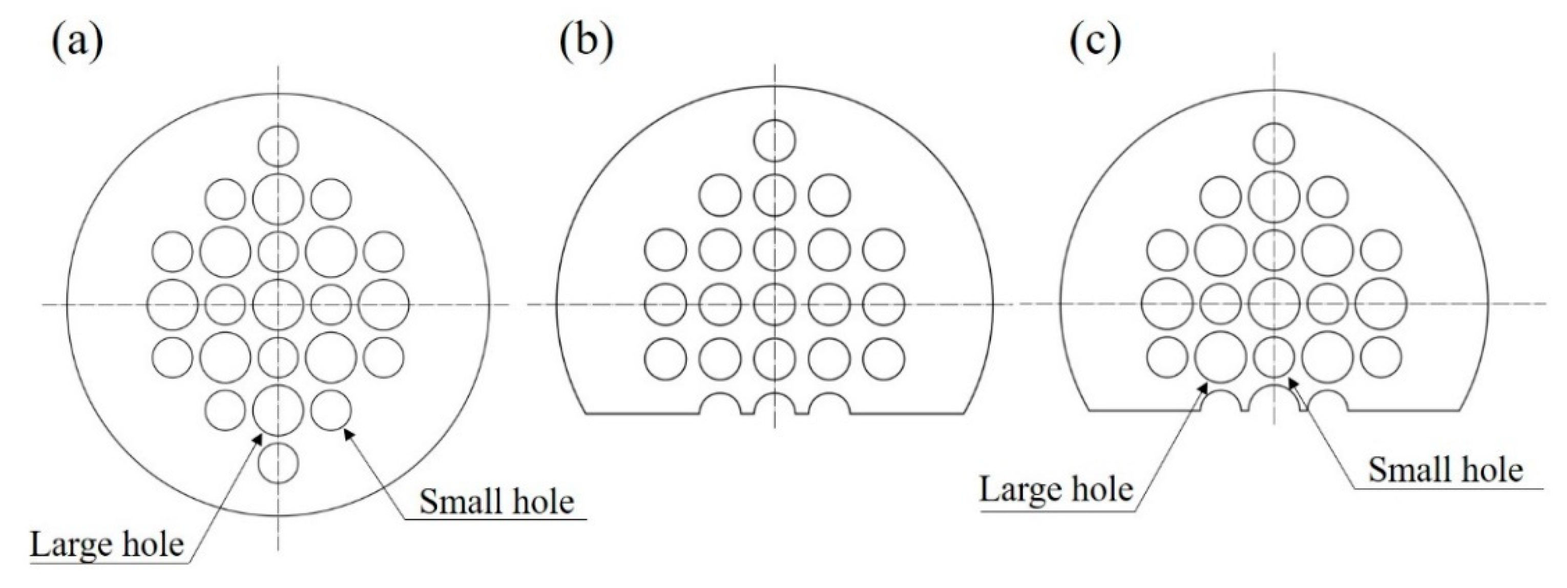
In this section, tube bundle vibration in heat exchangers with different baffles were examined numerically with a fluid-structure coupling approach. Three finite element models were established. One is using traditional segmental baffles with the height of the segmental cut of 25%D where the shell-side fluid flow is transverse. The second is using HDD baffles without the segmental cut where the shell-side fluid flow is longitudinal. The third is using HDD baffles with the height of the segmental cut of 25%D where the shell-side fluid flow is cross flow having both transverse and longitudinal components. Fluent module and Transient Structural module with Ansys Workbench 18.0 are were applied respectively for the fluid dynamic and transient dynamic analysis.
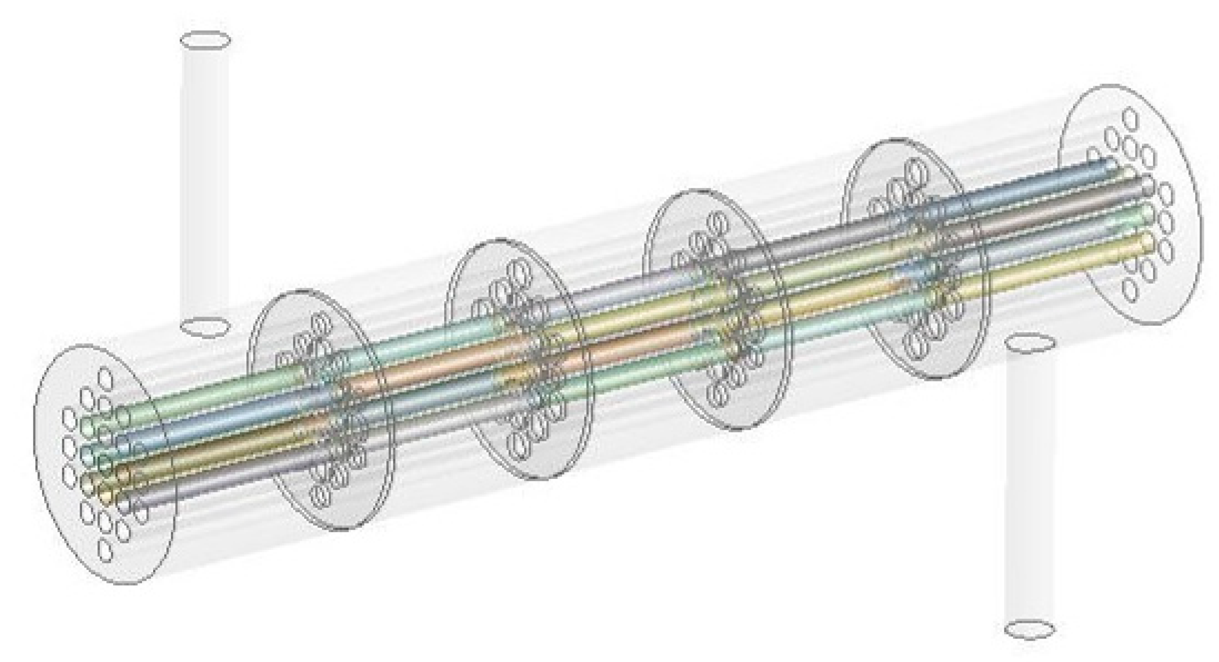
Figure 1 shows the three-dimensional model of the heat exchangers with HDD baffles. Detailed structural parameters are listed in
Table 1. The other two models are the same except for the structure of the baffles, as shown in
Figure 2. Considering the difficulties in fluid-structure coupling computation and the mutual influence of the adjacent tube vibration, nine tubes in the middle of the exchanger were treated to be elastic while others were set to be rigid without deformation while having geometrical boundaries. Shell elements were used to mesh the tubes.
For the boundaries, two ends of the tubes were fixed. As actual clearances exist between the tube holes and the tubes, no supports of the baffles on the tube vibration were considered in this analysis for conservative modeling. The contact faces between tube walls and shell-side fluid domain were set to be the contact surface of FSI. The inlet and outlet adopted velocity inlet and pressure outlet, respectively. After performing mesh independence tests, the final models had about 2,165,000 nodes and 766,430 elements. For the transient computation, the time step of 0.001 was applied.
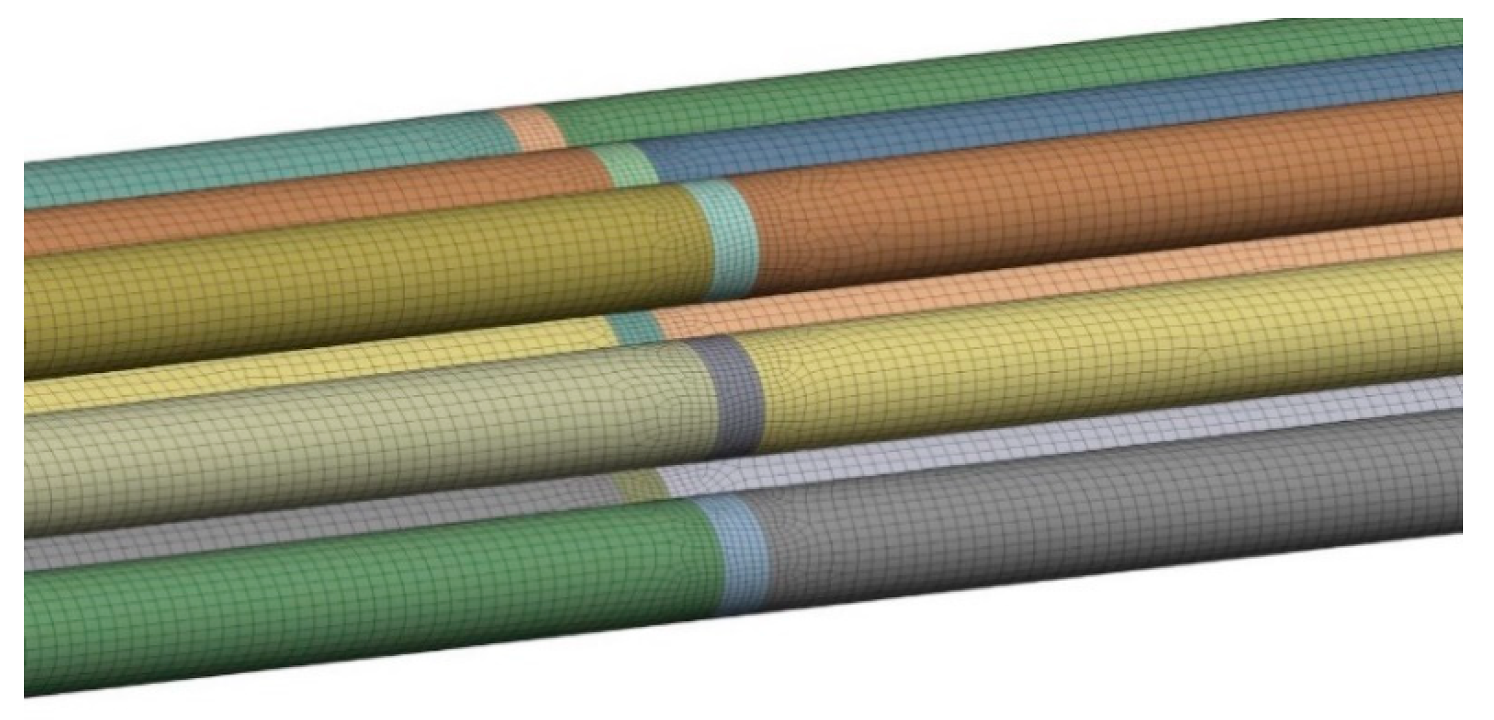
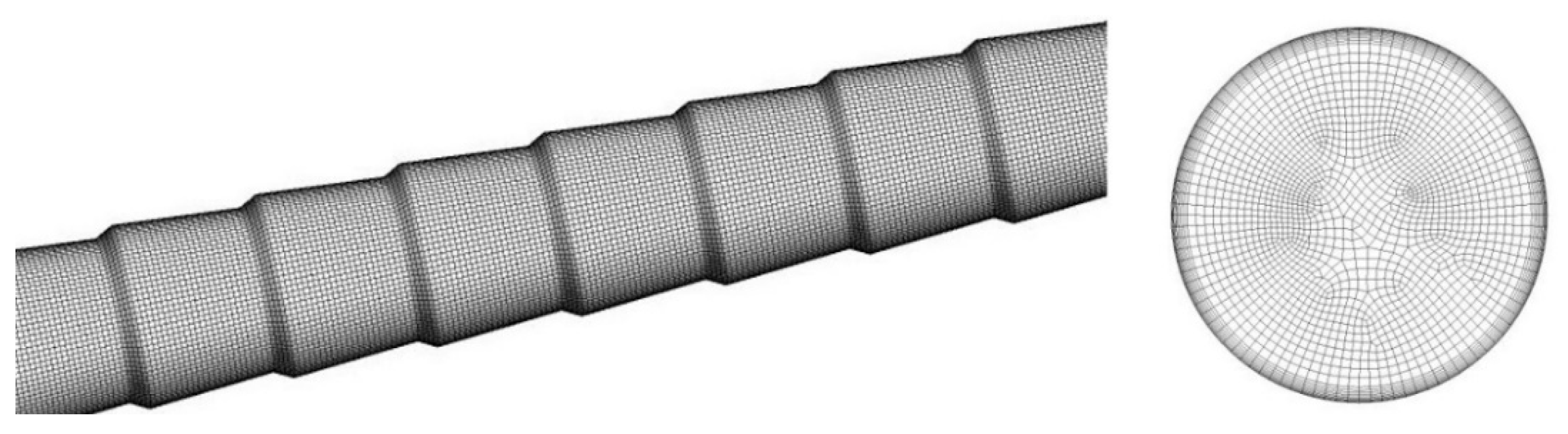
Figure 3 shows the grid model of the heat exchangers with HDD baffles and
Figure 4 shows the grid model of the tube bundle.
As mentioned before, tube vibrations will mutually influence the tube bundle induced by shell-side fluid flow. In order to mostly reflect the real situation, the tube at the center of the tube bundle in
Figure 4 was focused.
Figure 5 shows the vibrations at the middle of the tube for different models in the time domain. Clearly for the three baffles, the vibration of the tube bundle with the traditional segmental baffles is much larger than that of the tube bundle with HDD baffles without the segmental cut. As it also has some transverse flow, the vibration of the tube bundle with HDD baffles have a segmental cut that is also larger than that of the tube bundle with HDD baffles without a segmental cut.
The root-mean-square of the acceleration of vibration can be better reflect the serious the vibration [
24]. For the three vibrations in
Figure 5, the root-mean-squares of the acceleration are 1.5035 mm
2/s, 1.1830 mm
2/s, and 0.9494 mm
2/s, respectively, for traditional segmental baffles, HDD baffles with the segmental cut, and HDD baffles without the segmental cut. Clearly, the root-mean-square of the acceleration for HDD baffles without the segmental cut is the smallest, meaning that using HDD baffles, the tube bundle vibration can be significantly reduced.
Figure 6 shows the vibrations in the frequency domain. It is found that all the tube bundles with the three types of baffles are vibrated at low frequency. It turns out by performing model analysis that the first natural frequency of the tube is about 100 Hz.
Figure 6 shows a small bounce in amplitude at this frequency.
3. Heat Transfer Enhancement with Conically-Corrugated Tubes
Developing high-efficient heat transfer tubes has always been a hot issue for heat transfer enhancement. By rolling into different surface structures from the base smooth tubes, several profile tubes are used in engineering. Conically-corrugated tube is a new shape of high-efficiency heat transfer tube developed by the author.
Figure 7 illustrates the structure of the conically-corrugated tube which is one used in the heat exchanger for the experiments in
Section 4. In this section, fluid flow and heat transfer inside the conically-corrugated tube were numerically simulated and compared with other high-efficiency heat transfer tubes and smooth tubes.
Figure 8 shows the three-dimensional geometrical models of the high-efficiency heat transfer tubes including conically-corrugated tube, arc-corrugated tube, convergent-divergent tube, and spiral grooved tube.
Figure 9,
Figure 10,
Figure 11 and
Figure 12 show the grid models with the specific structural details for high-efficiency heat transfer tubes, which take the common structural parameters. At the same time, the pitch of the arc-corrugated tubes and convergent-divergent tubes is the same as that of the conically-corrugated tubes.
In this section, the commercial software ANSYS fluent 18.0 was used to simulate the fluid flow and heat transfer in the tubes. The standard turbulence model and scalable wall function were used. The governing equations were solved by SIMPLE algorithm. The pressure term was discretized by the standard scheme, and other variables were discretized by the second-order upwind scheme. The convergence criterion was that the energy residual curve reaches 10
−6 and the other variables were 10
−4. The boundary conditions of velocity inlet and pressure outlet were adopted, and the outlet pressure was set to zero, so the inlet pressure was the tube side pressure drop. The inlet fluid and tube wall temperatures were 323 k and 293 k, respectively. See
Table 2 for physical parameters of water. Taking the conically-corrugated tube as an example, the grid independence verification was carried out to ensure the accuracy of numerical research. The results are shown in
Table 3. Three groups of meshes are listed in the table. Through mesh refinement, the Nusselt number and resistance coefficient tends to be stable, and the relative error is less than 2%. Therefore, considering the calculation difficulty, the grid of 2,032,574 nodes is used for division.
In the heat exchanger area, the mean Nusselt number and friction coefficient are two important parameters. The former reflects heat transfer efficiency, and the latter indicates the flow resistance.
Figure 13a shows the mean Nusselt numbers changing with Reynolds number for different heat transfer tubes. It is found that the mean Nusselt number for conically-corrugated tubes were 110–130% larger than smooth tube and 11–17 and 26% larger than the high-efficiency spiral grooved tube and convergent-divergent tube, indicating conically-corrugated tube is the most for heat transfer enhancement.
Figure 13b shows friction coefficients changing with Reynolds number for different heat transfer tubes. As the cross section of the tube is constantly changing, all the friction coefficients of high-efficiency tubes are larger than that of the smooth tubes, meaning that the flow resistances inside high-efficiency tubes are raised compared with smooth tubes. But it is noted that enhancing heat transfer is the first consideration in the design of heat exchangers. At the same time, it is seen that the resistance coefficient of the conically-corrugated tube is lower than that of the arc-corrugated tube, which implies that the conically-corrugated tube has better comprehensive performance.
4. Heat Transfer Behavior of the Heat Exchanger with Conically-Corrugated Tubes and HDD Baffles
In this section, a heat exchanger constructed with conically-corrugated tubes and HDD baffles was tested to investigate the heat transfer behavior [
25]. The conically-corrugated tube was rolled from a smooth tube (base tube). Referring to
Figure 7, the outside diameter
d of the base tube was 25 mm; the thickness of the tube was 2.5 mm; the arc radius at the trough
R1, = 5 mm; the arc radius at the peak
R2, = 6 mm; and the pitch
S = 20 mm. Other structural parameters of the heat exchanger are listed in
Table 4. It should be pointed out that heat exchange tubes with an outside diameter 25 mm were most commonly used to construct shell-and-tube heat exchangers in chemical engineering. Selection of the heat exchange area, which determines the number and length of tubes or the diameter of the shell mainly of the tested heat exchanger, depends on the capability of the experimental system.
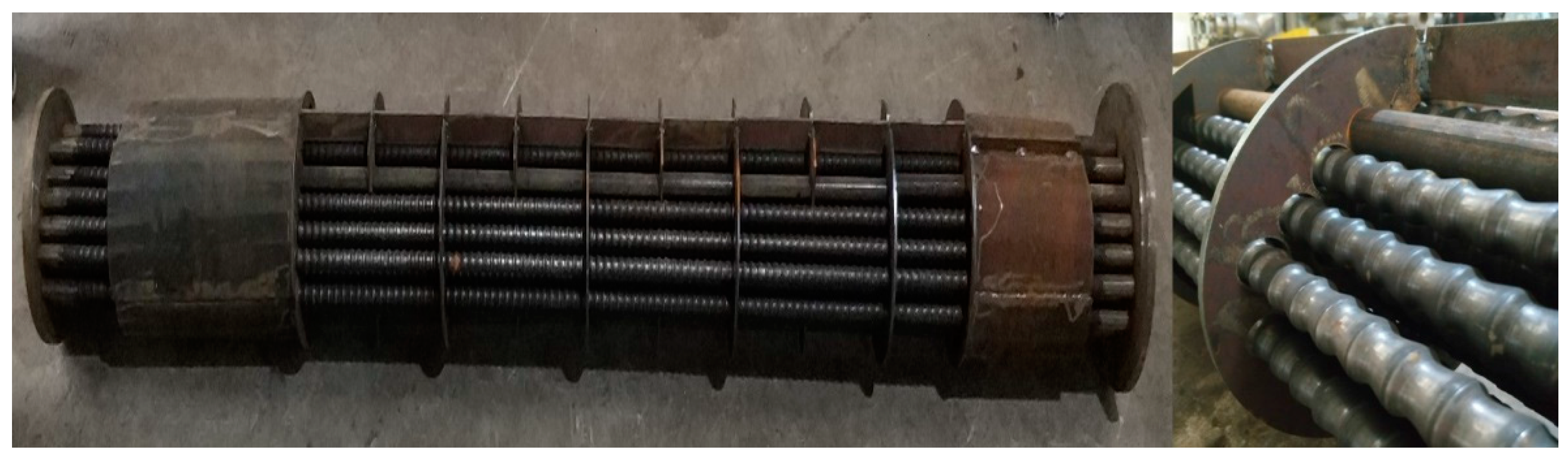
Figure 14 shows the conically-corrugated tube bundle of the exchanger. For comparison, a heat exchanger with smooth tubes and traditional segmental baffles was also manufactured and tested. The test medium was water with the properties listed in
Table 2.
The experimental device is schematically shown in
Figure 15. After being heated to the target temperature (about 70 °C) by the electric heater, the hot water in the hot water tank was pumped into the shell-side inlet of the heat exchanger. The cold water in the cold-water tank was also heated to the target temperature (about 30 °C) and then pumped into the tube-side inlet of the heat exchanger. The cold and hot fluids conducted heat exchange inside the heat exchanger, which is a double tube-side heat exchanger. During the tests, the flow rate on the shell or tube side was fixed while changing the flow rate on the other side. The tube-side flow rate and shell-side flow rate are 4.02 m
3/h–21.18 m
3/h and 6.09 m
3/h–45 m
3/h, respectively. In these ranges, the Reynolds number of the tube-side fluid was about 5000–30,000, and that of shell-side fluid was about 8000–60,000. By measuring temperatures at the inlets and outlets on both shell and tube sides and calculating the heat Q transferred and the temperature difference Δ
tm, the total heat transfer coefficient
K can be evaluated as:
where
A is the heat transfer area.
Figure 16 shows the total heat transfer coefficient changing with the tube-side flow rate while keeping the shell-side flow rate be constant as 45 m
3/h. It was found that compared with the heat exchanger with smooth tubes and traditional segmental baffle, the total heat transfer coefficient of the heat exchanger constructed with conically-corrugated tubes and HDD baffles was increased by 30–66%.
Figure 17 shows the total heat transfer coefficient changing with the shell-side flow rate while keeping the tube-side flow rate be constant as 26.26 m
3/h. It was found that compared with the traditional heat exchanger, the total heat transfer coefficient of the heat exchanger with conically-corrugated tubes and HDD baffles is increased by 9–18%.
From the above analysis, it was determined that if the heat exchanger is constructed with conically-corrugated tubes and HDD baffles, not only the tube bundle can be significantly reduced, but also the heat transfer efficiency can be remarkably increased.
5. Conclusions and Discussion
In this paper, vibrations of tube bundles with HDD baffles and fluid flow as well as heat transfer inside conically-corrugated tubes were numerically simulated and the heat exchanger with conically-corrugated tubes and HDD baffles were tested for the heat transfer efficiency. The main conclusions are drawn as follows.
- (1)
Compared with the traditional segmental baffles, tube bundle vibrations in heat exchangers using the HDD baffles can be significantly reduced.
- (2)
Regarding heat transfer efficiency, conically-corrugated tubes are much better than smooth tubes and even better than other high-efficiency heat transfer tubes. Specifically, its average Nusselt number is 11–17%, 26%, and 110–130% higher than that of spiral grooved tubes, convergent-divergent tubes, and smooth tubes, respectively. In addition, the resistance coefficient of conically-corrugated tubes was lower than that of arc-corrugated tubes.
- (3)
Experiments found that compared with the traditional heat exchangers, heat exchangers with conically-corrugated tubes and the HDD baffles can provide a large total heat transfer coefficient, i.e., better heat transfer efficiency. Specifically, in the range studied here, the total heat transfer coefficient of the heat exchanger with conically-corrugated tube and HDD baffle was 9–18% higher than that of the traditional segmental baffle when the tube side flow is kept constant.
It should be pointed out that both conically-corrugated tubes and HDD baffles are new components in shell-and-tube heat exchangers. So the novelty of the work is mainly to provide a new shell-and-tube heat exchanger constructed with conically-corrugated tubes and HDD baffles and has a higher efficiency heat transfer and less tube bundle vibration. But more studies and results are needed for the assessments and improvements in heat transfer of the heat exchanger studied here, including providing correlated equations for the heat transfer coefficients and friction coefficients of fluid flow on both tube-side and shell-side after performing sufficient parametric analysis and even structural optimization with necessary experimental validation. In addition, engineering applications are critically important to find the advantages and disadvantages of this new kind heat exchangers, especially for larger ones since it is hard to perform numerical simulations and experimental measurements of large heat exchangers, and for heat exchangers, results obtained for smaller heat exchanger cannot be readily applied to enlarged ones.


