Abstract
A comprehensive review is carried out on the models and correlations for solid/fluid reactions that result from a complex multi-scale physicochemical process. A simulation of this process with CFD requires various complicated submodels and significant computational time, which often makes it undesirable and impractical in many industrial activities requiring a quick solution within a limited time frame, such as new product/process design, feasibility studies, and the evaluation or optimization of the existing processes, etc. In these circumstances, the existing models and correlations developed in the last few decades are of significant relevance and become a useful simulation tool. However, despite the increasing research interests in this area in the last thirty years, there is no comprehensive review available. This paper is thus motivated to review the models developed so far, as well as provide the selection guidance for model and correlations for the specific application to help engineers and researchers choose the most appropriate model for feasible solutions. Therefore, this review is also of practical relevance to professionals who need to perform engineering design or simulation work. The areas needing further development in solid–fluid reaction modelling are also identified and discussed.
1. Introduction
Heterogeneous solid/fluid reactions have wide applications in chemical and metallurgical processes [1,2]. These include solid fuel combustion and gasification, elimination by solid sorbents in flue gas desulfurization, carbonation reaction including post-combustion capture, hydrogen production, energy storage, chemical vapor deposition, metal oxidation, reduction of solid oxides, dissolution of solids, and catalytic reactions, etc. [3,4,5]. It can produce fluid products, solid products or the mixture of fluid and solid products. These subjects have become more and more important in chemical engineering. In fact, a search on Web of Science with the keywords “solid reaction” and “chemical engineering” show an exponential increase over the years in the number of papers published in peer review journals as shown in Figure 1a.

Figure 1.
(a) Number of papers published every year with keywords “Solid Reaction” and “Chemical Engineering”; (b) papers published with keywords “solid reaction modelling” plus “single-particle model” versus “solid reaction modelling” plus “Computational Fluid Dynamics/CFD” according to Web of Science.
Comparing to homogeneous gas reaction [6,7], solid/fluid reaction is a more complex multi-scale physicochemical process, involving interactions among fluid flow, heat and mass transfer, and reaction kinetics. Its reaction rate is a crucial parameter to understand, design, control, and optimize the reaction process. However, determination of reaction rate has been remaining an important and challenging subject for the researchers and engineers since the last several decades. The reaction rate depends on several parameters, including particle shape, particle size, particle morphology, particle pore structure, chemical kinetics, fluid flow condition, and heat and mass transfer, etc. [8,9,10,11,12,13,14,15,16]. Furthermore, more complexity is added when the reactions occur in different types of reactors, including a reactor where particles are in suspension, a fixed bed reactor, and a fluidized bed reactor, which are most commonly used in practical applications.
Different modelling methods have been developed to solve the reaction rate over the last few decades, from simplified models to complex CFD models. The simplest model is the shrinking particle model or shrinking core model for nonporous particles. More complex models include the random pore model, which accounts for the particle pore structure and the diffusion and reaction inside the pores.
CFD modelling have been applied in solid/fluid reactions in various applications. Tabet and Gokalp [17] reviewed submodels used in CFD simulation for biomass/coal co-firing, including submodels for turbulent flow, particle dispersion, and gas/solid phase reactions, etc. Mathekga et al. [18] reviewed the development in oxy-fuel combustion in fluidized bed combustors in the areas including heat transfer, char combustion and pollutant emissions, etc. Kuma et al. [19] reviewed the submodels used in CFD simulation for biomass/coal co-firing in fluidized beds. Dernbecher et al. [20] reviewed CFD simulation for biomass combustion in fixed beds. Jurtz et al. [21] reviewed CFD modelling in fixed-bed reactors with geometric resolution of every pellet in the bed. Marangwanda et al. [22] reviewed the submodels used in CFD modelling for biomass combustion, with the emphasis on particle motion and particle surface area. The case of gas-producing boundaries (e.g., electrochemical applications) has been studied in [23,24].
While CFD simulation can provide detailed information on fluid dynamics and heat transfer in the solid/liquid reaction process, it is complex to build, requiring considerable computational resource and time. Therefore, for engineers who need a quick design of new product or process, or to perform a quick feasibility study or to evaluate or optimize the existing processes or operations within a limited time frame, CFD simulation could be too time-consuming to afford. In these cases, a quick modelling solution with appropriate correlations and empirical equations based on single particle reaction models becomes a desirable option.
Figure 1b shows that the interest in CFD modelling and single particle model is approximately the same in the literature, but, surprisingly, while there are many recent literature reviews on the CFD approach, as discussed in the above, no comprehensive literature review on single particle models have been carried out since 1982 [25].
There is a group of recent reviews whose title looks related to single particles models [26,27,28], but a closer analysis will reveal that they only refer to a few single particle models and mostly focus on the chemistry rather than on the overall process.
Therefore, to the best of our knowledge, this is the first comprehensive review on single particle models of the last decades. As such, it fills a precise gap in the literature. At the same time, this review also provides guidance for choosing the correct mode according to the circumstances, so that the engineers and researchers can identify the appropriate models and correlations for each specific case quickly among the variety of models available in the literature.
Figure 2 shows the general solid–liquid reaction model selection process that structures this review, which covers all the three main reactors commonly used in industrial applications, i.e., reactor with suspended particle, fixed bed reactor, and fluidized bed reactor. The reaction model and correlations for a single particle in suspension is first reviewed. Then the review is on particles in fixed bed, followed by reviews on particles in fluidized bed.
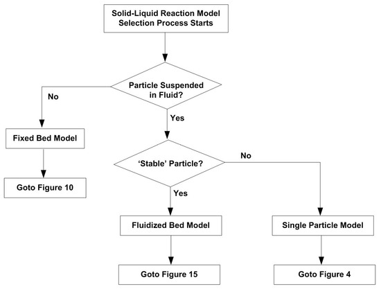
Figure 2.
Flowchart for Solid–Liquid Reaction Mode Selection Process (where ‘Stable’ Particle means that particle does not break and can from aggregates).
2. Single Particle Reaction Models
Different models have been developed over the last few decades for a single particle reaction. Generally, according to the variations of particle size and density during the reaction, there are three basic types of model.
The first type is shrinking particle model or shrinking core model. These are the models when the particle is nonporous, and the reaction can only occur at the particle surface. Then the reaction zone moves into the solid, leaving behind the reaction product and inert solid if there is any. In the shrinking core model, the unreacted core shrinks in size during the reaction. However, the overall particle size can either remain unchanged or shrinking as the reaction progresses [29]. The former cases include coal/biomass combustion, where ash is left behind after reaction, keeping the particle diameter approximately unchanged. Therefore, the shrinking core model is also called the product layer model by some investigators [14]. For the reactions with no product layers formed outside the unreacted core, when products are either dissolved in the surrounding fluid or removed immediately from the outer surface of the solid, the shrinking core model is also called shrinking particle model, such as in the case of pure carbon combustion in oxygen, and the solid/liquid reaction producing gas products [30,31,32,33].
Some investigators considered the cracking of the nonporous particle during the reaction, and proposed the cracking core model [34,35], which assumes that the initial nonporous particle is transformed to a grainy material, which then reacts following the shrinking core model. This cracking core model has some success in simulating systems where intermediate products are formed during the reaction [34].
The second type is called progressive conversion model or volumetric reaction model or continuous reaction model. This is when the particle is highly porous, the reactivity is low, and the fluid reactant has a high possibility of diffusing far into the porous solid before reacting with the solid reactant, such as the slow poisoning of a catalyst pellet. Therefore, it can be assumed that the reaction occurs throughout the particle at all times. In this case, the concentration of fluid is generally uniform throughout the solid with the same value as that of the bulk fluid stream. The pores will become larger and the overall rate is independent of the solid size. The overall solid size does not change until the solid particle is highly converted [32,36,37,38]. The reaction process is shown in Figure 3.
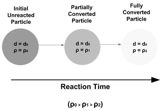
Figure 3.
Reaction process in progressive conversion model.
The third type is for the majority of porous particle reactions, where both the particle size and density reduce along the reaction process. In this case, the reaction can be seen as occurring homogeneously inside the solid. The homogeneous model has been developed to represent this scenario, including random pore model and grain model. The Ishid–Wen model [39] is developed for the cases where the reaction inside the pores is nonhomogeneous.
In summary, the reaction models developed for a single particle together with the model selection process, are shown in Figure 4.
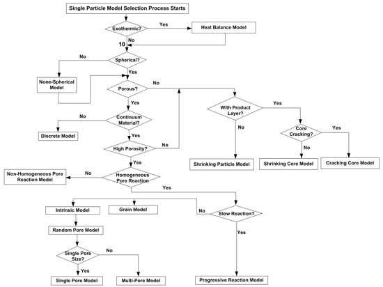
Figure 4.
Flowchart for singe particle reaction model selection process.
The details of each model shown in Figure 2 are discussed in the following sections.
2.1. Shrinking Core/Particle Model
In this process, three steps occur in succession. The first step is the diffusion of reactant form the bulk fluid to the particle surface through the concentration boundary layer, and the solid product layer if there is any. Then the reaction occurs on the particle surface. For reversible reaction, after that, the gas product is transported back to the bulk fluid via the diffusion. For irreversible reactions, only the first two steps apply. The resistance of each step usually varies greatly, where the step with the highest resistance is considered to be rate-controlling.
The following discussion takes an example of reactions without product layer outside the unreacted core. For the reactions with product layer, the analysis is similar except that an extra resistance, i.e., diffusion through the porous product layer, exists.
Depending on the relevant importance of bulk diffusion and surface reaction kinetics, the reaction rate can be diffusion-limited, kinetics-limited, or diffusion/kinetics-limited, which are to be introduced in the following.
2.2. Bulk Diffusion-Limited Process
In this process, the bulk mass transfer resistance is much higher than that in the chemical reaction process. Therefore, it is acceptable to assume that only bulk diffusion is considered.
Consider an irreversible first order reaction of solid and fluid producing gas product with and without solid product, which can be expressed as:
A (fluid) + bB (Solid) → Gas Product (+ Solid Product)
The overall reaction rate can be expressed as:
where is the external surface area of the particle, is the moles of the solid component, is the mass transfer coefficient in the concentration boundary layer, is the bulk fluid concentration.
The mass transfer coefficient depends on a number of parameters, including the relative velocity between particle and fluid, particle size, and fluid properties, etc. Various correlations have been developed to calculate the mass transfer coefficient. Ranz and Marshall have proposed the following correlation to account for the mass transfer of a component of mole fraction y in a fluid to free-falling solids [40]:
where is the particle density, is the particle diameter, is mass diffusivity, Sh is Sherwood number, Sc is the Schmidt number, Re is the Reynolds number, u is the fluid velocity.
In general, increases with the increase in fluid velocity, u, and the decrease in particle size.
Equation (2) shows that:
For small particle size and fluid velocity, Equation (2) can be simplified as:
Once is known, we can calculate the overall reaction rate from Equation (1).
By integrating Equation (1) with time, the time for complete reaction and the disappearance of the particle is:
where is the original radius of the particle at the beginning of the reaction.
2.3. Reaction Kinetics-Limited Process
When the characteristic time of mas transfer is considerably smaller than that of the chemical reaction, mass transfer is not the controlling mechanism and only the chemical reaction process is considered.
The rate of the reaction on the surface of the particle can be expressed as:
where is the rate constant for the first-order surface reaction, and:
where T is the particle surface temperature, A is the frequency factor, and is the activation energy, which can be obtained from the experiments where mass transfer is not the controlling mechanism. For nonporous material, this could be achieved by creating strong enough turbulent effects around the solid particles, so that the external mass transfer resistance can be suppressed. However, for porous particles, the mass transfer inside the pores still exists.
By integrating Equation (5) over time, the time required for complete reaction when the solid disappears is expressed as [41]:
where is the mole density of the particle . The higher the , the larger the reaction rate.
2.4. Combination of Resistances—Diffusion/Kinetics Limited Reaction
The above two cases (Section 2.2 and Section 2.3) assume that a single resistance controls the overall reaction process. However, this assumption may not be reasonable and applicable in processes when the bulk mass diffusion resistance is of the same order of magnitude of the surface reaction. Also, the relative importance of these two resistances could vary as the reaction proceeds with the decrease in particle size and the increase in particle temperature for exothermic reactions. Therefore, the resistances from the two processes need to be considered at the same time.
Since the bulk mass diffusion and surface reaction processes are in series, the total reaction time is the sum of these two processes as:
The overall reaction rate is then expressed as:
where is the fluid concentration on the particle surface.
Then combining the individual resistance, i.e., , and from Equations (1) and (5), we have:
2.5. Effect of Particle Size
When solids and liquids react, the reaction rate will increase with the increase in the surface area of the solid. Under the same mass, the solid’s total surface area increases with the decrease in particle size. Therefore, the reaction rate increases with the decrease in particle size. (We do not consider here the possibility of particle breakup, which can occur in several application [42].)
For the reactant solid with multiple particle sizes, Knorr et al. [12] has studied the effect of particle size distribution on the reaction rate for the production of carbide-derived carbon from silicon carbide. The Langmuir–Hinshelwood kinetics model, which is reported to represent the carbide chlorination process better than power law rate expression, has been used in the simulation [43]. They found a higher conversion rate when using the mean particle diameter, as shown in Figure 5. They attributed the slower conversion rate with particle size distribution than that with mean particle size to the large particles existed in particle size distribution, which slows down the reaction because of lower specific surface area and more evident diffusion effects.
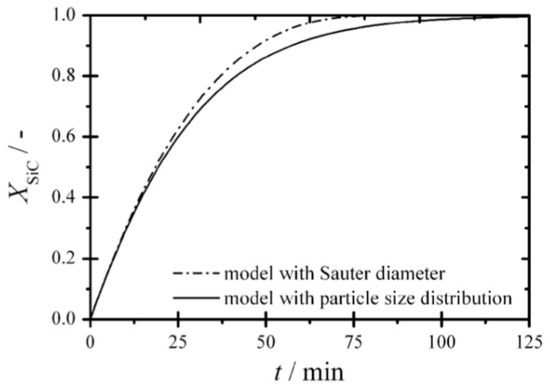
Figure 5.
Effect of mean particle size and particle size distribution on reaction rate [12] (Copyright Elsevier).
2.6. Effect of Relative Fluid/Solid Velocity
For external diffusion limited or diffusion/kinetics limited reactions, the relative velocity between particles and fluid could enhance the heat and mass transfer coefficients, and thus the overall reaction rate. The higher the velocity, the higher the bulk mass transfer coefficient and the overall reaction rate. However, when the reaction is kinetics limited and the reaction is isothermic, the influence of relative fluid/solid velocity and the bulk diffusion on the overall reaction rate is negligible [44,45,46].
2.7. Effect of Particle Temperature and Heat Transfer
For exothermic reactions, the heat transfer between the particle and the fluid and the particle temperature also affect the overall reaction rate.
For fast reaction, the rate of heat release could be high enough to cause evident temperature gradients inside the particles or between the particle and the bulk fluid. This case is discussed in detail by Wen and Wang [47].
The temperature field in the reactor is determined by reaction heat release, heat transfer between particle and fluid, and heat losses [48]. If a particle is very small with an infinite thermal diffusivity and a finite mass diffusivity, i.e., when , the particle temperature can be assumed to be uniform. Then the heat balance equation on a particle can be expressed as:
where is specific enthalpy of reaction heat release, is specific heat of the particle, is convective heat transfer coefficient, and is the emissivity of the particle.
The heat balance for the bulk fluid is given by:
where is heat loss from the bulk fluid to the surroundings.
The thermal conductivity of the particle is reduced by the presence of voids and ash if there is any. Internal temperature gradients are likely for particle with the diameter of as small as 40 μm. Heating rate also affects the heat transfer inside the particle. Annamalai and Ryan [40] estimated the Internal temperature gradients could be several hundred degrees at a high heating rate of kJ/s for 35 μm particles. However, even for larger particles of 100 μm, the temperature difference decreases to 40 K when the heating rate is less than kJ/s.
2.8. Effect of Particle Shape
Particle shape also affects the reaction rate, as the surface areas are different for different particle shapes.
For nonporous particles with irregular particle shapes, Salmi et al. [14] used shape factor, a, to represent the effects of particle shape, as:
and,
Then:
where and are the reaction surface area and the volume of the particle, respectively, and R is the characteristics dimension of the particle.
Salmi et al. [14] found that the overall reaction rate increases with the increase in shape factor. They also found that for particles with radius larger than 5–10 μm, the reaction is closer to first order with the increase in shape factor.
Aris [49,50] reported that for a diffusion-limited first-order reaction, the predicted conversion rates are close to each other for all shapes studied.
For porous particles, Salmi et al. [51] concluded that the classical solid/liquid models based on ideal, nonporous geometries, i.e., spheres, infinite cylinder, and slab cannot predict the reaction accurately. Comparing to nonporous particle, the effect of particle shape on reaction rate for porous particles is more difficult to identify, as the particle structural properties varies during the reaction. Therefore, various simplifications have been proposed in the previous investigations in order to quantify the influence of particle shape on reaction rate. The most commonly used simplification is to represent the irregular particle shape with three regular shapes, whichever is the closest in geometry. They are sphere, slab and rectangle. Recently, Turbetskaya et al. [52] recommended to use an infinite cylinder together with the volume-to-surface ratio to represent a biomass particle, which normally has a large aspect ratio in geometry, after conducting an experimental study using light microscope and 2D dynamic imaging analysis. Most of the previous numerical studies concentrated on simulating a cylindrical particle with 1D model assuming parameters varying only along the radial direction [53,54,55,56,57]. The cylindrical particle is divided into a number of spherical shells in the radial direction, and finite volume method is used to solve the governing equations [55]. Haseli et al. [53] developed a 1D model for a single biomass particle combustion for cylindrical, spherical, and slab particles. Saastamoinen et al. [57] used 1D model simulating large spherical biomass particles. Yang et al. [58] performed a two-dimensional simulation of a cylindrical wood particle.
Another investigator [59] used an enhancement factor to account for the enhancement effect of particle shape on reaction rate of biomass particles. However, this enhancement method does have shortcomings because it generalizes the cylindrical and prism shape for biomass particles [22]. Therefore, all the existing models for particle shape effect for porous particles are overly simplified. There is no general model to describe the effect of the shape of porous particles on reaction rates, which needs to be addressed in the future study.
2.9. Effect of Particle Surface Morphology and Pore Diffusion
Instead of being smooth and continuous, the particle surface usually is rough, and the particle can have internal cracks and to be porous. Moreover, scanning electron microscopy have revealed that real particles often significantly differ from the ideal ones, showing cracks and craters. This can be shown in Figure 6a. Therefore, the specific surface area of a real particle could be higher than that of an ideal smooth surface.
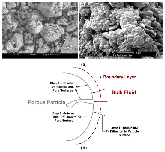
Figure 6.
(a) SEM images of real reactive solid (Salmi et al. [14]) (Copyright Elsevier); (b) Steps of porous char combustion.
For porous particles, the reaction process includes bulk fluid diffusion, the fluid diffusion inside the pores, and surface chemical reaction, which is shown in Figure 6b:
In general, the diffusivity inside the pores is lower than the bulk continuum diffusivity due to small pore sizes.
The relevant importance of each diffusion and chemical reaction process can vary during the reaction. Li et al. [60] find an abrupt transition from fast reaction regime to slow reaction regime in carbonation reaction when the thickness of the product layer reaches a critical value, beyond which, the reaction becomes slow as the diffusion of reacting species throughout the product layer becomes dominant.
The models for reactions between fluid and porous particle can be classified into continuous models and discrete ones [61]. In a continuum model, the porous particle is treated as a continuum where temperature, solid species concentrations and fluid species concentrations are defined as smooth functions of location and time. In a discrete model, the material is as assumed to be a collection of elements such as voids and crystallites, etc.
In a continuum model, the transport coefficients, i.e., the diffusivity, the reactivity coefficients, the surface area, and density, are expressed as functions of the solid structure.
For porous particle reaction, particle structural properties, such as porosity and internal surface area, are important parameters for fluid diffusion through the pores and for a kinetically controlled reaction limited by internal surface area. Also, particle size and density decrease during the reaction (density decreases because of reaction also occurs inside the pores).
When the particles are highly porous, the shrinking core model is not representative anymore. To account for this and the diffusion and reaction inside the pore, various models have been proposed, including intrinsic model, grain model and random pore model, which are introduced in the following sections.
The expansion of the shrinking core model for porous particles resulted in the grain model, firstly proposed by Sezekely et al. [62], where a porous particle is assumed to be composed by spherical nonporous grains, and the voids between them represent the porosity. Bhatia and Perlmutter [63] developed a random pore model, where the porosity is represented by cylindrical pores which are randomly interconnected inside the particle.
Bahrami et al. [64] compared the conversion rate predictions from modified grain model, random pore model, and volume reaction model for CuO/SO2 reaction, with the experimental data, and found that random pore model produces the closest prediction to the experimental data, and is recommended for solid/gas reaction model.
Namkung et al. [56] reported an evident deviation between experiment and simulation using both shrinking pore model and volumetric reaction model for combustion of char from biomass and coal particles, as shown in Figure 7. This shows that shrinking pore model and volumetric reaction model are not able to simulate porous particle reaction with a reasonable accuracy. Models dedicated to porous particle should be resorted to in this case.
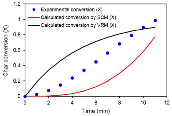
Figure 7.
Comparison of char conversion rate between experiment and simulation (where SCM refers to Shrinking Core Model, and VRM refers to Volumetric Reaction Model) (Namkung et al. [56]) (Copyright Elsevier).
Porosity, specific surface area, and pore size are three important parameters which define pore structure. Therefore, they have significant impact on porous particle reactions.
2.9.1. Intrinsic Model
For porous particles, the diffusion inside the pores also affects the overall reaction rate. Smith [25] has proposed an intrinsic model to include the effects of pore diffusion for coal combustion. The model is based on the effectiveness factor describing diffusion effects in the pores, which is the ratio between the actual combustion rate and the rate attainable if no pore diffusion resistance exists. This model has been widely applied in solid fuel combustion and gasification [65,66].
In this model, the chemical rate coefficient, , is determined by three interacting factors, i.e., the intrinsic rate of chemical reaction, the internal surface area, and the extent to which bulk fluid diffusion through the pores. The char combustion can be expressed as [44]:
where is the effective reaction rate coefficient.
Specifically, the intrinsic char combustion rate can be expressed as:
where is char particle mass, is the bulk mass transfer coefficient, is the mass fraction of oxygen, is the molecular weight of oxygen, and is intrinsic reaction rate considering the effects of pore diffusion and chemical reaction on internal surface of char particle.
can be calculated with [44]:
where is the mass diffusion limited rate constant.
Field et al. [67] proposed the following empirical equations to calculate :
and
where D is the bulk fluid diffusion coefficient. Field et al. [67] proposes a value of at 1500 K for pulverized coal combustion.
is explicitly expressed in terms of the intrinsic chemical and pore diffusion rates as:
where η is the effectiveness factor, is the intrinsic reaction rate constant.
The effectiveness factor is calculated by:
where is the Thiele modulus, and is given by:
where is the effective diffusion coefficient in the particle pores, which is determined by the particle porosity, . It relates to unit cross-sectional area of porous particle and thus considers the effect of the size and number of the pores in the unit cross-section and τ, which is the tortuosity of these pores [44]. Assuming the bulk and Knudsen diffusions proceed in parallel (for gas only) and the particle is isotropic, i.e., the pore size distribution is unimodal, and can be calculated by:
where is the molecular diffusion coefficient through the pores (either continuum or Knudsen, or both), τ is the tortuosity of the pores, which is a measure of pore curvature, is Knudsen diffusion coefficient. Pores with a high tortuosity lead to frequent collisions of gas molecules with pore walls, thus resulting in a reduced effective diffusivity. Another reason for a high tortuosity is attributed to a large pore length. It is between 2 and 6 normally, and approximately 2 for char [40]. Bhatia and Perlmutter [63] reported that the value of pore tortuosity is usually between 1.5 and 2.0. τ is given the value of , corresponding to average intersecting angle between external surface and pores of 45° (Backreedy et al. [44]).
According to the model of Wakao and Smith (Smith [25]):
where is the molecular weight of the diffusing fluid, is the mean pore radius of char particle, and is taken as m (Backreedy et al. [44]). This value is chosen because it is consistent with previous measurements. It is found that the computations are sensitive to the value chosen, with an 8% increase in the burning rate when the value is 6 × 10⁻⁸ m.
Wheeler [48] proposed the following expression to calculate :
where is particle surface area.
For large pores with pore size higher than 1 μm, and when bulk diffusion dominates, then:
For small pores with pore size less than 1 μm, and when Knudsen diffusion dominates, then:
Smith [25] proposed the following expression to calculate :
where .
Several models exist to estimate the molecular diffusion coefficients for gases and liquids. The Chapman–Enskog equation and the Fuller–Schettler–Giddings equation, are often used to estimate the binary diffusion coefficients for gas No generally accepted correlation exists so far for the estimation of binary liquid diffusion coefficients. The Wilke–Chang equation (Miyabe and Isogai [68]) has been widely used in the literature, which is expressed as:
where f is the factor for solute-solvent interaction, is molar volume of solute at boiling point, T is temperature, is the molecular weight of solvent, μ is the solvent viscosity.
Although the Wilke–Chang equation is widely used for the estimation of D in liquid systems (Miyabe and Isogai [68]), it cannot be applied for all the liquid phase systems, unless the value of f is known.
Another correlation is Stokes–Einstein equation, which is expressed as:
where is Boltzmann’s constant, is the solute radius, T is temperature.
The intrinsic char particle reactivity, is given by:
where is the intrinsic activity energy and can be obtained from the experiments.
A burning mode parameter, β, which relates the char particle diameter to the burnout fraction, U, has been defined by Smith [25], which gives an accurate description of the char particle size and density variations during combustion:
where:
where the subscript of 0 refers to the initial state. is between 0 and 1/3, and the value of 1/3 represents a decreasing char particle size with constant density, while the value of 0 represents a constant char particle size with a decreasing density. For most porous particle, both density and diameter decrease during the reaction. Therefore, a value between 0 and 1/3 for applies. For coal combustion, normally this value is chosen as 0.25 (Backreedy et al. [44]).
is the specific surface area of the particle and is often set at a constant value. Its mean value increases from the initial value of the char formed after pyrolysis during char combustion. Backreedy et al. [44] proposed a method to calculate the variation of the average char surface using coal maceral content. With this method, a factor, defined as α, which is function of char burnout determined from experiments, is introduced. Then Equation (20) can be rewritten as:
A base value of 0.01 m2/kg is used for , based on a typical value for the exposed carbon surface area.
Salmi et al. [14] reported the following relationship between the shape factor and particle accessible reaction surface area:
where is the particle accessible reaction surface area, is the particle molar mass, and n is the particle molar amount, a is the shape factor.
The following expressions are given for for the particles with the shape of sphere, cylinder and slab by Annamalai and Ryan [40]:
For sphere:
For cylinder:
For slab:
Sohn and Fan [16] reported that the initial rate should not be used for analysis of solid/fluid reaction kinetics, especially when the effect of pore diffusion starts to appear. It is found that the range of conditions under which the initial reaction rate can represent the intrinsic kinetics is very narrow, even in the absence of external mass transfer effects.
2.9.2. Random Pore Model
It can be seen from the above that the specific surface area is an important factor for porous particle reaction. A random pore model (RPM) has been proposed by Bhatia and Perlmutter [63] to calculate the specific surface area.
The RPM developed by Bhatia and Perlmutter [63] assumes that the particles pores are an assembly of randomly oriented cylinders. The pore diameters of the unreacted particle generally start to increase during reaction, leading to increased total reaction surface area, until pore overlapping is dominant. The surface area of the consuming particle exhibits a maximum level and starts to decrease until the entire particle is consumed. The initial particle structural properties, which are two dimensionless structural parameters, i.e., porosity and , determine the conversion time curve shape.
The reaction rate with RPM is expressed as [69]:
where:
where is a structural parameter containing the effect of pore-size distribution, X is the conversion of the solid, n, k is the reaction rate constant, is the initial total pore length, is the initial porosity, is the initial pore specific surface area. is the bulk fluid concentration, t is time, and τ is the dimensionless time in random pore model. , and can be obtained from porosimetry measurement.
Except for using the original pore size distribution to calculate , as shown in Equation (43), it is usually estimated by fitting to experimental measurement data [65].
RPM is also expressed with another formula as [70]:
where X is the conversion faction, and is expressed as:
where r is reaction front velocity.
It should note that the term of the exponent in Equation (44) is the particle volume when the pore radius is increased with the propagation of the reaction front. The bracket multiplied with the exponential term represents the contribution of the external surface area of the particle.
In RPM, S depends on the solid material type and changes with the conversion, X, as:
For biomass char, an assumption of a monotonous increasing pore size without any pore merging is made [65,71]. Dasappa et al. [71] argued that this assumption is more relevant for the ordered structure of wood than that of coal, for which the RPM was originally developed. This assumption implies that the specific surface area increases continuously. Then the following is obtained:
By further assuming that the pores grow due to the radial expansion, the following expression is obtained by [61]:
Fatehi and Bai [65] compared the predictions from a random multi-pore model with a random single-pore model. They classified the pore size in a few bands, as in Table 1:

Table 1.
Pore structure properties of different band of pore sizes (Fatehi and Bai [65]) (Copyright Elsevier).
They found that the specific surface area increases much faster with the multi-pore model than that in the single-pore model, and the predicted reaction is also closer to the experimental data, as shown in Figure 8.
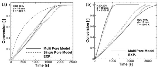
Figure 8.
Comparison of reaction rates from random pore models (a) Comparison between multi pore model, single pore model and experimental data; (b) Comparison between multi pore model and experimental data (Fatehi and Bai [65]) (Copyright Elsevier).
3. Reaction Models for Bed of Particles
Besides a single particle surrounded by fluid, as reviewed in the previous section, fixed bed and fluidized bed have also been used for the reactions involving large number of particles [72,73]. Fluid–solid fluidization occurs when particles are suspended in the flowing fluid and exhibit fluid-like properties. This can be achieved through either external forced draft or internally generated gas products which lift the particle.
Depending on the operational conditions, three hydrodynamic regimes can be found, i.e., bubbling fluidized bed, turbulent fluidized bed, and circulating fluidized bed [74]. A fluidized bed can be represented by a single bulk density and considered to be a heterogeneous mixture of fluid and solid.
All fluidized beds start as fixed beds with a minimum height when the fluid velocities are low. Further increasing the fluid velocity leads to a bubbling fluidization regime, with a high degree of mixing between the gas and solids phases in the case of gas-fluidized beds. In a bubbling fluidized bed with a relatively lower gas velocity, small gas bubbles are generated and grow up while rising in the bed. These bubbles become larger and less stable when the gas velocity is further increased, which are easy to break up. As a result, the fluidized bed begins to expand and transits from the bubbling to turbulent regimes, under which the fluctuations of the solid–gas flow inside the fluidized bed reaches its maximum, and the coalescence of the bubbles and the rates of the breakup reach the equilibrium [74,75]. The different fluidization regimes are shown in Figure 9.

Figure 9.
Fluidization regimes of bed of particles ((a) Fixed bed; (b) Minimum fluidization; (c) Smooth fluidization; (d) Bubbling fluidization; (e) Slugging (Axial slugs); (f) Slugging (Flat slugs); (g) Turbulent fluidization; (h) Lean phase fluidization with pneumatic transport) (Kunii and Levenspiel [74]) (Copyright Elsevier).
Minimum fluidization velocity is required in order for the particles to become fluidized from a fixed bed. The fluidization velocity is the gas velocity calculated for the free cross-sectional area of the grate at bed pressure and temperature. The minimum fluidization velocity is the velocity where the fluid drag is equal to a particle’s weight and substracting its buoyancy.
The value of this minimum fluidization velocity depends on a number of parameters, including the size, shape, and polydispersity of the particles and the mode gas is injected into the system [76,77]. For example, the density, directly alters the net gravitational force on the particle, and therefore the minimum drag force, or velocity, required to lift a particle. The shape alters not only the relationship between the velocity and the drag force, but also the packing properties of the fixed bed, the associated void spaces and velocity of fluid through them.
When the fluid velocity is sufficiently high, the drag on an individual particle will exceed the gravitational force on the particle, and the particle will be entrained in the fluid and carried out of the bed. The point at which the drag on an individual particle is about to exceed the gravitational force exerted on it is the maximum fluidization velocity. Therefore, the entering fluid velocity must be above the minimum fluidization velocity and below the maximum fluidization velocity in order to maintain a bubbling or turbulent fluidized bed.
Compared to a fixed bed, a fluidized bed can induce intense mixing and contact between particles and fluid, leading to enhanced heat and mass transfer. Therefore, a thermal uniformity can be assumed to be similar to a well-mixed gas. Therefore, the fluidized bed can have high thermal capacity while maintaining a homogeneous temperature field. The diffusion also plays a less important role in fluidized bed because of higher heat and mass transfer rates between the gas and solid comparing to fixed bed.
3.1. Reaction Models for Fixed Bed of Particles
A fixed bed of particles can be found in different applications, including waste incineration, etc. In fixed-bed reaction, comparing to bulk mass diffusion, the reaction could be fast enough to assume that any volume element of the reaction system contains only one or other of the reactants, but not both, i.e., the reaction is instantaneous. The flowchart for fixed-bed reaction modelling is shown in Figure 10.
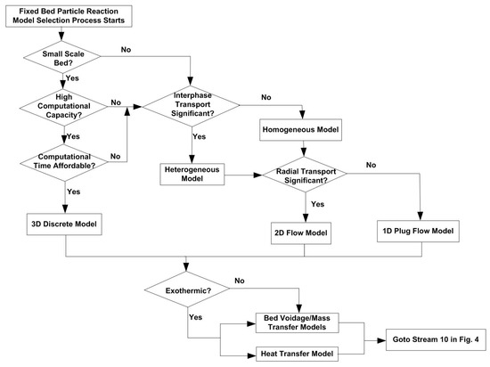
Figure 10.
Flowchart for fixed bed particle reaction modelling process.
3.1.1. Continuum and Discrete Fixed-Bed Model
For fixed-bed modelling, continuum model, i.e., treating fluid and solid phases as pseudo-continuum has been the most applied approach [78]. Both 1D plug flow and 2D continuum models have been used [4,37,79,80,81,82,83]. If computational power permits, a 3D discrete particle model can be applied [84,85,86,87]. Dixon and Medeiros [88] compare a 3D discrete particle model to 1D/2D continuum models for the steam methane reforming process. Similarities and discrepancies between these two approaches are presented.
Bremer and Sundmacher [3] modelled the fixed-bed reactor using a 1D homogeneous plug-flow model with negligible axial back-mixing. The plug-flow is able to represent the fixed beds because of a high Bodenstein number between 1000 and 10,000. Davoodi et al. [89] also used a dispersed plug flow model with an axial dispersion coefficient to simulate the unconventional oil removing process in fixed and fluidized beds, assuming particles are spherical and homogeneous in size and density.
Fixed-bed modelling has been carried out by several investigators on DME producing process using methanol dehydration. Ghavipour and Behbahani [81] investigated the methanol dehydration process in fixed bed with a 1D heterogeneous plug flow model. Unsteady-state simulation is performed to model the reactor start-up process. The methanol reaction rate and the reactor thermal performance are compared under adiabatic and nonadiabatic conditions. They found nonadiabatic reactor has a lower conversion rate and the maximum temperature moves to the end of the reactor. Nasehi et al. [82] simulated an industrial adiabatic fixed-bed reactor under steady-state conditions and found negligible difference in the results from 1D and 2D modelling. Bercic and Levec [79] modelled an adiabatic fixed-bed reactor using both 1D heterogeneous and a pseudo-homogeneous plug flow model and found that the intraparticle mass transfer is the rate-controlling step when using a 3-mm γ-Alumina pellets as the catalyst. Ngo et al. [37] used a 1D plug flow model to simulate fixed-bed catalytic reactors for CO2 methanation. A 2D pseudo-homogeneous model has been developed by Zhu et al. [83] to simulate the performance of fixed-bed reactors for catalytic coupling reaction of CO to diethyl oxalate. They found that coolant temperature has a significant effect on reactor bed temperature.
Karthik and Buwa [84] conducted a 3D simulation to model heat transfer, fluid flow, diffusion and reaction inside a fixed-bed reactor, inside which vinyl acetate is synthesized by acetylene and acetic. They found strong inhomogeneity inside the bed due to randomly fixed catalytic particles. High-speed channels and dead zones behind particles were observed in the fixed bed. It was found that the reaction rate decreased dramatically from outside to the center of each particle. Increasing the pore size can evidently promote the average reaction rate.
3.1.2. Bed Voidage Modelling
Benyahia and O’Neill [90] measured the mean bed voidage data for particles, both nonporous and porous, with different shapes fixed in a cylindrical tube, using the water displacement method, and found the following relationship, as shown in Figure 11.
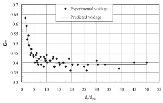
Figure 11.
Mean voidage in fixed beds of spherical particles (Benyahia and O’Neill [90], reprinted by permission of the publisher (Taylor & Francis Ltd.).
They further drew the following general expression for bed voidage:
where is the mean bed voidage, is the tube diameter, is the equivalent sphere diameter, and is the particle sphericity.
The above equation has a multiple correlation coefficient of 0.95 with an average error of 5.2% and is valid for , and .
However, in practice, real particles, e.g., biomass particles, have irregular shape. There is no general correlation for voidage of bed with irregular particle shapes available. Therefore, more research is needed in this area.
3.1.3. Heat and Mass Transfer in Fixed Bed
Langer et al. [91] have investigated a fixed bed of glass balls where methane gas flows through, and drawn the following expression for the axial mass transfer coefficient from the gas to the bed:
where τ is the reciprocal axial tortuosity, is the molecular diffusion coefficient, w is the interstitial velocity of flow, and is the Peclet number at infinite velocity.
Wicke [92] proposed the following relationship between τ and the bed void fraction, ε:
and
where is the volume occupied by particles, and is the bed volume.
Bischoff [93] found that for average fixed columns:
Using a highly turbulent random walk model, the theoretical value of β is 8.
For a cylindrical bed, w is calculated by:
where V is the volumetric flow rate of the fluid, and is the column diameter.
If the fluid is stagnant, then Equation (49) can be rewritten as:
Shin and Choi [94] has used the following 1D combustor to study the combustion rate of the solid fuel in a fixed bed, to represent the fixed bed waste combustion in an incinerator.
For spheres in a convective environment, Sh or Nu can be modified using the following correlations using the droplet combustion literature.
The following equations have been used for convective heat transfer and mass transfer to the bed, where the mass transfer coefficient was modelled using the analogy with convective heat transfer [29,94]:
For forced convection:
Marshall correlations are expressed as [40]:
where the velocity used in Re calculation is the relative velocity between the particle and the fluid.
For natural convection [40]:
When the combustion in the bed proceeds, the loss of mass in the bed causes decrease in surface area for heat and mass transfer and chemical reaction and also the height for the control volume of the bed. The shrinkage of the control volume of the bed equals to u. The particles’ external surface area is modelled by Shin and Choi [94]:
where the initial surface area in the control volume, , is calculated from [40,94]:
where is the bed void fraction, is the bed volume, and is the particle diameter.
3.1.4. Effect of Reactant Fluid Inlet Temperature
Chen et al. [95] simulated the catalytic syngas dehydrogenation reaction in a fixed-bed reactor. They found that the reaction rate is very sensitive to reactant gas inlet temperature. When the inlet temperature is 404.2 K, the H2 conversion is around 15%. However, the H2 conversion increases to nearly 100% when the inlet temperature increases to 410.2 K, as shown in Figure 12a.
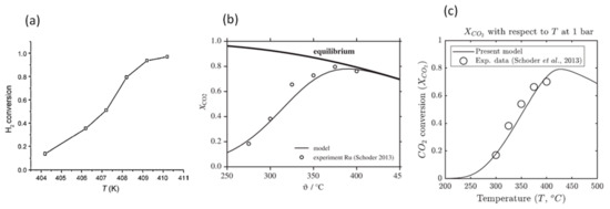
Figure 12.
Effect of reactant inlet temperature on reaction rate (a) (Chen et al.) [95] (Copyright Elsevier); (b) (Kiewidt and Thoming [96]) (Copyright Elsevier); (c) (Ngo et al. [37]) (Copyright Elsevier).
Kiewidt and Thoming [96] simulated the catalytic conversion of CO2 into methane in a fixed bed, with a pseudo-homogeneous plug flow model. They considered a reversible CO2–CH4 conversion reaction and found that CO2 conversion increases with the increase in inlet temperature until around 380 °C, then decreases with the further increase in inlet temperature, due to the limitation of thermodynamic equilibrium in this reversible reaction process, as shown in Figure 12b. This variation trend in CO2 conversion was also found by Ngo et al. [37], where the critical temperature is around 425 °C, where the maximum CO2 conversion of 0.8 is reached, as shown in Figure 12c.
3.1.5. Effect of Bed Temperature
Maroufi et al. [97] simulated a noncatalytic gas–solid fixed-bed reactor with 1D plug flow model for the reactor, and the grain model for the particles. They predicted the axial temperature distribution in the bed and found that conversion rate increases considerably with the increase in bed temperature.
3.1.6. Effect of Particle Size
Scaltsoyiannes and Lemonidou [98] studied the effects of particle size when simulating CaCO3 decomposition process. By decreasing the particle size, the external heat and mass transfer processes become faster. Reducing particle size also decreases the species concentration gradient inside the pores, until the minimum value is reached, where it can be approximated with the value at the particle’s external surface. They found that the reaction rate increases when the particle diameter is decreased from 500 to 100 μm. Beyond the limit of 100 μm, the internal resistance reaches a minimum, and the reaction rate remains almost constant, as shown in Figure 13. Edwards and Materić [99] also reported that the internal mass transfer is negligible when the particle size is smaller than 90 μm. However, Hu and Scaroni [100] observed that the internal mass transfer is significant for particles sized between 9 and 90 μm when studying the calcination of limestone in a drop tube furnace. Therefore, this critical particle size below which the particle internal mass transfer becomes insignificant depends on the specific application conditions.
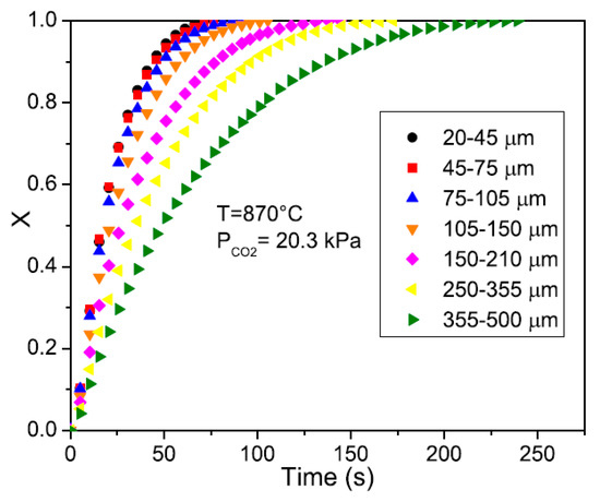
Figure 13.
Effect of particle size on conversion rate (Scaltsoyiannes and Lemonidou [98]) (Copyright Elsevier).
3.1.7. Effect of Space Velocity (SV)
Chen et al. [95] simulated the catalytic dehydrogenation reaction of syngas in a fixed-bed reactor. The effect of reactant gas space velocity on H2 production rate is shown in Figure 14a. It can be seen that when SV is lower than 2200 , the reaction rate increases with the increase in SV. This is because when SV increases, the Reynolds number increases, resulting in enhanced heat and mass transfer, which leads to increased reaction rate. However, when the SV is greater than 2300 , the reduced residence time of reactant gas mixture in the reactor leads to decreased reaction rate, which outweighs the increase in reaction rate caused by a larger Reynolds number. Therefore, they recommended that the range between 2200 and 2200 is the optimized space velocity.
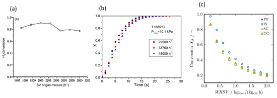
Figure 14.
The effect of space velocity on reaction rate (a) (Chen et al. [95]) (Copyright Elsevier); (b) (Scaltsoyiannes and Lemonidou [98]) (Copyright Elsevier); (c) (Donaubauer et al. [101]) (Copyright Elsevier).
Scaltsoyiannes and Lemonidou [98] simulated CaCO3 decomposition in a fixed-bed reactor, and concluded the space velocity has a negligible influence on CaCO3 conversion rate in their investigation range, which is between 22,500 and 45,000 , with only a slight decrease in CaCO3 decomposition rate with the increase in space velocity, as shown in Figure 14b. Donaubauer et al. [101] reported a steady decrease in conversion with the increase in space velocity in all the four models tested for a fixed-bed reactor, as shown in Figure 14c. This decrease is the result of the reduced residence time of the reactant in the reactor.
Therefore, space velocity, or the flow rate of reactant fluid, can increase, decrease, or have negligible influence on the reaction rate in the fixed bed, depending on the specific application conditions.
3.2. Reaction Models for Fluidized Bed of Particles
In the fluidized bed system, the performance of the reactor is affected by the hydrodynamic behaviors of the reactor in that fluid dynamics affects both heat and mass transfer [102].
The flowchart for fluidized bed particle reaction model selection process is shown in Figure 15.
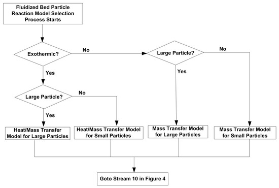
Figure 15.
Flowchart for fluidized bed particle reaction model selection process.
When fluidizing a fixed bed, the working fluid pressure is increased until the pressure drop between the top of the bed (where fluid leaves) and the bottom of the bed (where fluid enters) is equal to the weight of the fixed solids. At this point, the velocity of the fluid is just not enough to achieve fluidization. Extra pressure is required to overcome the between-particle frictions the frictions between the particle and the wall of the reactor, in order to achieve fluidization. This gives a minimum fluidization [103].
The minimum fluidization velocity is an important parameter to differentiate a fluidized bed from a fixed bed. Many research efforts have been carried out to obtain this velocity [104]. It can be calculated as [74,103]:
where and are the fluid density and viscosity, respectively, d is the particle diameter, Ar is Arquimedes number, and is calculated as:
where are densities of particle and gas, respectively, and is the particle viscosity.
The bed voidage is the volume fraction of the bed occupied by solid particles. It can be calculated from pressure drop, , and height of fluidized bed, H, as:
Gomez-Barea and Leckner [105] presented the following correlations for heat and mass transfer coefficients for particles in fluidized bed:
For large particles:
For small particles:
3.2.1. Effects of Particle Size
Particle size has a significant influence on heat and mass transfer in the fluidized bed, and finally the reaction conversion rate. The smaller the particle size, the stronger the heat and mass transfer, and the higher the conversion. This is because on one hand, the smaller the particles, the thinner the gas gap, and thus the lower the gas gap conduction resistance; on the hand, finer particles have larger surface areas, increasing convective heat transfer from particles to the fluid.
Figure 16a shows the enhancement of heat transfer coefficient with the decrease in the particle size:
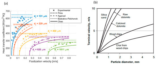
Figure 16.
Effect of particle size on (a) heat transfer coefficient in fluidized bed (Berg et al. [106]) (Copyright Elsevier); (b) terminal velocity in fluidized bed (Gomez-Barea and Leckner [105]) (Copyright Elsevier).
Gomez-Barea and Leckner [105] found that the maximum fluidization velocity, i.e., the terminal velocity, increases with the increase in particle size, as shown in Figure 16b.
3.2.2. Effects of Fluidization Velocity
Fluidization velocity can increase the heat and mass transfer and thus enhance the conversion rate. Das et al. [107] found the following variation trends of moisture content loss rate under different fluidization velocities. It can be seen that the higher the fluidization velocity, the faster the drying process, as shown in Figure 17a.
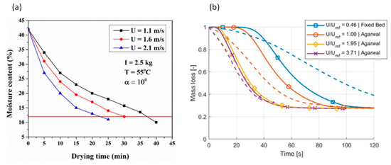
Figure 17.
Effect of fluidization velocity on reaction rate in fluidized bed (a) (Das et al. [107]) (Copyright Elsevier); (b) (Berg et al. [106]) (Copyright Elsevier).
Berg et al. [106] compared the conversion rates under different fluidization velocities in a fluidized bed with that in a fixed bed, and obtained the following trends, as shown in Figure 17b, where U is the fluidization velocity, and is the minimum fluidization velocity. The dash lines are experimental results and the solid lines are for simulation results.
It can be seen from this diagram that there is a significant increase in conversion rate when the fixed bed becomes fluidized when the minimum fluidization velocity is reached. Beyond that, the conversion rate also increases quickly when the fluidization velocity is 1.95 times of the minimum fluidization velocity. However, when the fluidization velocity is further increased to 3.71 times of the minimum fluidization velocity, only a slight increase in conversion rate is observed.
It can also be found from the above diagram that the modelling results agree well with the experimental data when the fluidization velocity is well above the minimum fluidization velocity. However, the discrepancies between them are high when the fluidization velocity is equal or below the minimum fluidization velocity, indicating the need for further improvement in the model in this region.
3.2.3. Effects of Bed Temperature
As the same for a single particle, for the fluidized bed, the higher the bed temperature, the higher the conversion rate. This increase is shown in Figure 18a,b, where the fluidization velocity is kept unchanged while varying the bed temperature [106,107]:
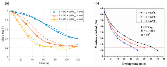
Figure 18.
Effects of bed temperature on reaction rate in fluidized bed (a) (Berg et al. [106]) (Copyright Elsevier); (b) (Das et al. [107]) (Copyright Elsevier).
3.2.4. Effects of Particle Load
Cui et al. [102] studied the fluidization performance of silicon carbide in a fluidized bed and found that the minimum fluidization velocity increases with the increase in particle load under all particle sizes. Generally, the larger the particle size, the higher the increasing rate in minimum fluidization velocity as increasing the particle load. They also found that increasing the particle size also increases the minimum fluidization velocity, as shown in Figure 19.

Figure 19.
Effect of particle load on minimum fluidization velocity (Cui et al. [102]) (Copyright Elsevier).
4. Conclusions
A comprehensive review has been conducted on models for solid/fluid reaction, encountered in a wide range of engineering applications, especially in solid fuel combustion. At the same time, model selection guidance for each of the three major types of reactors is also provided. This review can help engineers and researchers choose the most appropriate model and correlations for a quick engineering design, feasibility study, or the existing process evaluation or optimization, especially when complex and time-consuming CFD simulation is impractical or unavailable. Specifically, the following conclusions can be drawn, along with the areas which need further investigation in the future:
- (1)
- The shrinking core model or shrinking particle model is suitable for nonporous particles. The progressive reaction model or volumetric reaction model is suitable for slow reaction of porous particle, such as the slow poisoning of a catalyst pellet. However, these two models are not suitable for porous particles with fast reaction rates, such as solid fuel combustion. The random pore model combined with the intrinsic reaction model is the most widely used model for a porous particle reaction with satisfactory accuracy;
- (2)
- The prediction accuracy for a porous particle reaction rate is heavily dependent on the accuracy of the input data acquired through experiments. These include the pore structure properties, mass diffusion coefficients inside and outside the pores, and intrinsic kinetic parameters, etc., which vary with particle size and heating rate;
- (3)
- While it has been widely recognized that the particle shape has a significant influence on biomass particle reaction rate, the common basic assumptions used in the available models are still to simply the actual irregular shape to a few simple regular ones, including sphere, slab and cylinder. However, this simplification could cause considerable prediction errors. There is still a lack in a general approach to account for the effect of particle shape on porous particle reaction so far. More research efforts should be dedicated to this important area in the future;
- (4)
- 1D homogeneous plug-flow model is most commonly used in practical engineering applications to simulate particle reactions in a fixed bed, while 3D discrete particle model requires significant computational time though attracting increasing academic research interest recently;
- (5)
- The critical particle size below which the particle internal heat and mass transfer becomes insignificant depends on the specific application conditions;
- (6)
- The flow rate of reactant fluid, can increase, decrease, or have negligible influence on the reaction rate in the fixed bed, depending on the specific application conditions;
- (7)
- There is a lack of a general correlation for voidage of bed for practical particles, which normally have irregular shapes. Therefore, more research efforts are needed in this area;
- (8)
- The hydrodynamic behaviors of the fluidized bed reactor have a significant influence on the performance of the reactor, such as fluid dynamics affects both heat and mass transfer. In a fluidized bed reactor, the smaller the particle size, the stronger the heat and mass transfer, and the higher the conversion rate;
- (9)
- Fluidization velocity can increase the heat and mass transfer and thus enhance the conversion rate. The minimum fluidization velocity increases with the increase in particle load;
- (10)
- The modelling of particle reactions in a fluidized bed needs to be further developed and improved in the future, especially when the fluidization velocity is equal or below the minimum fluidization velocity.
Author Contributions
Conceptualization, A.A. and L.D.; methodology, A.A. and L.D.; writing—original draft preparation, L.D.; writing—review and editing, A.A. and I.M.; supervision, A.A.; project administration, A.A.; funding acquisition, A.A. All authors have read and agreed to the published version of the manuscript.
Funding
This research was funded by the Defence Science and Technology Laboratory (DSTL), grant number DSTLX-1000140317.
Institutional Review Board Statement
Not applicable.
Informed Consent Statement
Not applicable.
Data Availability Statement
Not applicable.
Acknowledgments
This work was supported by the Defence Science and Technology Laboratory (DSTL), Grant DSTLX 1000140317.
Conflicts of Interest
The authors declare no conflict of interest.
References
- Grenman, H.; Salmi, T.; Murzin, D.Y. Solid-liquid reaction kinetics―experimental aspects and model development. Rev. Chem. Eng. 2011, 27, 53–77. [Google Scholar] [CrossRef]
- Salmi, T.; Warna, J.; Tolvanen, P. Understanding of solid–fluid kinetics and mass transfer: From ideal to non-ideal models, from perfect spheres to moon landscape. Front. Chem. Eng. 2020, 2, 1–9. [Google Scholar] [CrossRef]
- Bremer, J.; Sundmacher, K. Operation range extension via hot-spot control for catalytic CO2 methanation reactors. React. Chem. Eng. 2019, 4, 1019–1037. [Google Scholar] [CrossRef] [Green Version]
- Hussain, R.; Blank, J.H.; Elbashir, N.O. Modelling the fixed-bed fischer-tropsch reactor in different reaction media. Comput.-Aid. Chem. Eng. 2015, 37, 143–148. [Google Scholar]
- Toporov, D.D. Combustion of Pulverized Coal in a Mixture of Oxygen and Recycled Flue Gas; Elsevier: Amsterdam, The Netherlands, 2014. [Google Scholar]
- Dong, L.L.; Leung, C.W.; Cheung, C.S. Combustion optimization of a slot flame jet impingement system. J. Energy Inst. 2003, 76, 80–88. [Google Scholar]
- Dong, L.L.; Cheung, C.S.; Leung, C.W. Combustion optimization of a port-array inverse diffusion flame jet. Energy 2011, 36, 2834–2846. [Google Scholar] [CrossRef]
- Fan, L.S.; Miyanani, K.; Fan, L.T. Transient analysis of isothermal fluid-solid reactions system: Modeling the sigmoidal conversion-time behaviour of a gas-solid reaction. Chem. Eng. J. 1977, 13, 13–20. [Google Scholar] [CrossRef]
- Gibilaro, L.J.; Jioia, F.; Greco, G. Unsteady-state diffusion in a porous solid containing dead-ended pores. Chem. Eng. J. 1970, 1, 85–90. [Google Scholar]
- Carberry, J.J. Chemical and Catalytic Reaction; McGraw-Hill: New York, NY, USA, 1976. [Google Scholar]
- Greaves, M.; Dong, L.L.; Rigby, P.S. Simulation study of the toe-to-heel air injection three-dimensional combustion cell experiment and effects in the mobile oil zone. Energy Fuels 2012, 26, 1656–1669. [Google Scholar] [CrossRef]
- Knorr, T.; Kaiser, M.; Glenk, F.; Etzold, B.J.M. Shrinking core like fluid solid reactions—A dispersion model accounting for fluid phase volume change and solid phase particle size distributions. Chem. Eng. Sci. 2012, 69, 492–502. [Google Scholar] [CrossRef]
- Liu, M.; Mostaghimi, P. Numerical simulation of fluid-fluid-solid reactions in porous media. Int. J. Heat Mass Transf. 2018, 120, 194–201. [Google Scholar] [CrossRef]
- Salmi, T.; Grenman, H.; Warna, J.; Murzin, D.Y. Revisiting Shrinking Particle and Product Layer Models for Fluid-Solid Reactions―From Ideal Surfaces to Real Surfaces. Chem. Eng. Process. Process. Intensif. 2011, 50, 1076–1084. [Google Scholar] [CrossRef]
- Sohn, H.Y. General approach to fluid-solid reaction analysis and modelling. In Fluid-Solid Reactions, 2nd ed.; Elsevier: Amsterdam, The Netherlands, 2020. [Google Scholar]
- Sohn, H.Y.; Fan, D.Q. On the initial rate of fluid-solid reactions. Metall. Mater. Trans. B 2017, 48, 1827–1832. [Google Scholar] [CrossRef]
- Tabet, F.; Gokalp, I. Review on CFD based models for co-firing coal and biomass. Renew. Sustain. Energy Rev. 2015, 51, 1101–1114. [Google Scholar] [CrossRef]
- Mathekga, H.I.; Oboirien, B.O.; North, B.C. A review of oxy-fuel combustion in fluidized bed reactors. Int. J. Energy Res. 2016, 40, 878–902. [Google Scholar] [CrossRef]
- Kumar, H.; Mohapatra, S.K.; Singh, R.I. Review on CFD modelling of fluidized bed combustion systems based on biomass and co-firing. J. Inst. Eng. 2018, 99, 449–474. [Google Scholar] [CrossRef]
- Dernbecher, A.; Dieguez-Alonso, A.; Ortwein, A.; Tabet, F. Review on modelling approaches based on computational fluid dynamics for biomass combustion systems. Biomass Convers. Biorefin. 2019, 9, 129–182. [Google Scholar] [CrossRef]
- Jurtz, N.; Kraume, M.; Wehinger, G.D. Advances in fixed-bed reactor modeling using particle-resolved computational fluid dynamics (CFD). Rev. Chem. Eng. 2019, 35, 139–190. [Google Scholar] [CrossRef] [Green Version]
- Marangwanda, G.T.; Madyira, D.M.; Babarinde, T. Combustion models for biomass: A review. Energy Rep. 2020, 6, 664–672. [Google Scholar] [CrossRef]
- Alexiadis, A.; Dudukovic, M.P.; Ramachandran, P.; Cornell, A.; Wanngård, J. Liquid–gas flow patterns in a narrow electrochemical channel. Chem. Eng. Sci. 2011, 66, 2252–2260. [Google Scholar] [CrossRef]
- Alexiadis, A.; Cornell, A.; Dudukovic, M.P. Comparison between CFD calculations of the flow in a rotating disk cell and the Cochran/Levich equations. J. Electroanal. Chem. 2012, 669, 55–66. [Google Scholar] [CrossRef]
- Smith, I.W. The combustion rate of coal chars: A review. In 19th Symposium (International) on Combustion/The Combustion Institute; The Combustion Institute: Pittsburgh, PA, USA, 1982; pp. 1045–1065. [Google Scholar]
- Sohn, H.Y. Review of fluid-solid reaction analysis―Part 1: Single nonporous reactant solid. Can. J. Chem. Eng. 2019, 97, 2061–2067. [Google Scholar] [CrossRef]
- Sohn, H.Y. Review of fluid-solid reaction analysis―Part 2: Single porous reactant solid. Can. J. Chem. Eng. 2019, 97, 2068–2076. [Google Scholar] [CrossRef]
- Sohn, H.Y. Review of fluid-solid reaction analysis―Part 3: Complex fluid-solid reactions. Can. J. Chem. Eng. 2019, 97, 2326–2332. [Google Scholar] [CrossRef]
- Iwaszenko, S.; Howaniec, N.; Smolinski, A. Determination of random core model parameters for underground coal gasification simulation. Energy 2019, 166, 972–978. [Google Scholar] [CrossRef]
- Bhatia, S.K. The effect of pore structure on the kinetics of fluid-solid reactions. Ph.D. Thesis, University of Pennsylvania, Philadelphia, PA, USA, 1981. [Google Scholar]
- Gonzalez, J.A. Coupled fluid-solid thermal interaction modelling for efficient transient simulation of biphasic water-steam energy systems. Appl. Math. Model. 2020, 79, 566–593. [Google Scholar] [CrossRef]
- Son, H.Y.; Roy, S. Fluid-solid reaction kinetics for solids of non-basic geometries: Application of the law of additive times in combination with the shape-factor methods. Metall. Mater. Trans. B 2020, 51, 601–610. [Google Scholar] [CrossRef]
- Wen, C.Y. Noncatalytic heterogeneous solid–fluid reaction models. Ind. Eng. Chem. 1968, 60, 34–54. [Google Scholar] [CrossRef]
- Martins, J.P.; Margarido, F. The cracking and shrinking model for solid–fluid reactions. Mater. Chem. Phys. 1996, 44, 156–169. [Google Scholar] [CrossRef]
- Park, J.Y.; Levenspiel, O. The cracking core model for the reaction of solid particles. Chem. Eng. Sci. 1975, 30, 1207–1214. [Google Scholar] [CrossRef]
- Gago, P.A.; Raeini, A.Q.; King, P. A spatially resolved fluid-solid interaction model for dense granular packs/soft-sand. Adv. Water Resour. 2020, 136, 103454. [Google Scholar] [CrossRef] [Green Version]
- Ngo, S.I.; Lim, Y.I.; Lee, D.; Go, K.S.; Seo, M.W. Flow behaviours, reaction kinetics, and optimal design of fixed- and fluidized-beds for CO2 methanation. Fuel 2020, 275, 117886. [Google Scholar] [CrossRef]
- Zhou, Z.; Yan, D.; Zhu, J.; Zheng, Y.; Li, H.; Zhu, Q. Simulation of the fluid-solid noncatalytic reaction based on the structure-based mass-transfer model: Shrinking core reaction. Ind. Eng. Chem. Res. 2020, 59, 17729–17739. [Google Scholar] [CrossRef]
- Ishid, M.; Wen, C.Y. Comparison of kinetic and diffusional models for solid-gas reactions. AIChE J. 1968, 14, 311–317. [Google Scholar] [CrossRef]
- Annamalai, K.; Ryan, W. Interactive processes in gasification and combustion―II. isolated carbon, coal and porous char particles. Prog. Energy Combut. 1993, 19, 383–446. [Google Scholar] [CrossRef]
- Ishida, M.; Wen, C.Y.; Shirai, T. Comparison of zone-reaction model and unreacted core shrinking model in solid-gas reactions―Non isothermal analysis. Chem. Eng. Sci. 1971, 26, 1043–1048. [Google Scholar] [CrossRef]
- Cao, H.; Karampalis, D.; Li, Y.; Caragay, J.; Alexiadis, A.; Zhang, Z.; Fryer, P.J. Abrupt disintegration of highly porous particles in early stage dissolution. Powder Technol. 2018, 333, 394–403. [Google Scholar] [CrossRef] [Green Version]
- Becker, P.; Glenk, F.; Kormann, M.; Popovska, N.; Etzold, B.J.M. Chlorination of titanium carbide for processing of nanoporous carbon: A kinetic study. Chem. Eng. J. 2010, 159, 236–241. [Google Scholar] [CrossRef]
- Backreedy, R.I.; Fletcher, L.M.; Ma, L.; Pourkashanian, M.; Williams, A. Modelling pulverized coal combustion using a detailed coal combustion model. Combust. Sci. Technol. 2006, 178, 763–783. [Google Scholar] [CrossRef]
- Scott Fogler, H. Chapter 11: External diffusion effects on heterogeneous reactions. In Elements of Chemical Reaction Engineering; Pearson Education: London, UK, 2008. [Google Scholar]
- Scott Fogler, H. Chapter 12, Diffusion and reaction. In Elements of Chemical Reaction Engineering; Pearson Education: London, UK, 2008. [Google Scholar]
- Wen, C.Y.; Wang, S.C. Thermal and diffusion effects in noncatalytic solid gas reactions. Ind. Eng. Chem. 1970, 62, 30–51. [Google Scholar] [CrossRef]
- Wheeler, A. Reaction rates and selectivity in catalyst pores. Adv. Catal. 1951, 3, 249–327. [Google Scholar]
- Aris, R. On shape factors for irregular particles―I. the steady-state problem. Diffus. React. Chem. Eng. Sci. 1957, 6, 262–268. [Google Scholar] [CrossRef]
- Aris, R. On shape factors for irregular particles―II. the transient problem. heat transfer to a packed bed. Chem. Eng. Sci. 1957, 7, 8–14. [Google Scholar] [CrossRef]
- Salmi, T.; Grenman, H.; Warna, J.; Murzin, D. New modelling approach to liquid-solid reaction kinetics: From ideal particles to real particles. Chem. Eng. Res. Des. 2013, 91, 1876–1889. [Google Scholar] [CrossRef]
- Trubetskaya, A.; Beckmann, G.; Wadenback, J.; Holm, J.K.; Velaga, S.P.; Weber, R. One way of representing the size and shape of biomass particles in combustion modelling. Fuel 2017, 206, 675–683. [Google Scholar] [CrossRef] [Green Version]
- Haseli, Y.; van Oijen, J.A.; de Geoy, L.P.H. A detailed one-dimensional model of combustion of a woody biomass particle. Bioresour. Technol. 2011, 102, 9772–9782. [Google Scholar] [CrossRef]
- Lu, H.; Robert, W.; Peirce, G.; Ripa, B.; Baxter, L.L. Comprehensive study of biomass particle combustion. Energy Fuels 2008, 22, 2826–2839. [Google Scholar] [CrossRef]
- Momeni, M.; Yin, C.; Kar, S.; Hvid, S.L. Comprehensive study of ignition and combustion of single wooden particles. Energy Fuels 2013, 27, 1061–1072. [Google Scholar] [CrossRef]
- Namkung, H.; Lee, Y.J.; Park, J.H.; Song, G.S.; Choi, J.W.; Choi, Y.C.; Park, S.J.; Kim, J.G. Blending effect of sewage sludge and woody biomass into coal on combustion and ash agglomeration behaviour. Fuel 2018, 225, 266–276. [Google Scholar] [CrossRef]
- Issac, M.; Girolamo, D.; Dai, B.; Hosseini, T.; Zhang, L. Influence of biomass blends on the particle temperature and burnout characteristics during oxy-fuel co-combustion of coal. J. Energy Inst. 2020, 93, 1–14. [Google Scholar] [CrossRef]
- Yang, Y.B.; Sharifi, V.N.; Swithenbank, J.; Ma, L.; Darvell, L.I.; Jones, J.M.; Pourkashanian, M.; Williams, A. Combustion of a Single Particle of Biomass. Energy Fuels 2008, 22, 306–316. [Google Scholar] [CrossRef]
- Yin, C.; Rosendahl, L.; Kar, S.K.; Condra, T.J. Use of numerical modeling in design for co-firing biomass in wall-fired burners. Chem. Eng. Sci. 2004, 59, 3281–3292. [Google Scholar] [CrossRef]
- Li, Z.; Fang, F.; Tang, X.; Cai, N. Effect of temperature on the carbonation reaction of cao with CO2. Energy Fuel 2012, 26, 2473–2482. [Google Scholar] [CrossRef]
- Sahimi, M.; Gavalas, G.R.; Tsotsis, T.T. Statistical and continuum models of fluid-solid reactions in porous media. Chem. Eng. Sci. 1990, 45, 1443–1502. [Google Scholar] [CrossRef]
- Sezekely, J.; Evans, J.W. A structural model for gas-solid reactions with a moving boundary. Chem. Eng. Sci. 1970, 25, 1091–1107. [Google Scholar] [CrossRef]
- Bhatia, S.K.; Perlmutter, D.D. A random pore model for fluid-solid reactions: II. diffusion and transport effects. AIChE J. 1981, 27, 247–254. [Google Scholar] [CrossRef]
- Bahrami, R.; Ebrahim, H.; Halladj, R. Comparison of random pore model, modified grain model, and volume reaction model predictions with experimental results of SO2 removal reaction by CuO. J. Ind. Eng. Chem. 2015, 30, 372–378. [Google Scholar] [CrossRef]
- Fatehi, H.; Bai, X.S. Effect of pore size on the gasification of biomass char. Energy Procedia 2015, 75, 779–785. [Google Scholar] [CrossRef] [Green Version]
- Kleinhans, U.; Halama, S.; Spliethoff, H. The role of gasification reactions during pulverized solid fuel combustion: A detailed char combustion model based on measurement of char structure and kinetics for coal and pre-treated biomass. Combust. Flame 2017, 284, 117–135. [Google Scholar] [CrossRef]
- Field, M.A.; Gill, D.W.; Morgan, B.B.; Hawksley, P.G.W. Combustion of Pulverized Coal; British Coal Utilization Research Association: Surrey, UK, 1967. [Google Scholar]
- Miyabe, K.; Isogai, R. Estimation of molecular diffusivity in liquid phase systems by the Wike-Chang equation. J. Chromatogr. A 2011, 1218, 6639–6645. [Google Scholar] [CrossRef]
- Bhatia, S.K.; Perlmutter, D.D. A random core model for fluid-solid reactions: I. isothermal, kinetic control. AIChE J. 1980, 26, 379–385. [Google Scholar] [CrossRef]
- Scaltsoyiannes, A.; Antzaras, A.; Koilaridis, G.; Lemonidou, A. Towards a generalized carbonation kinetic model of CaO-based materials using a modified random pore model. Chem. Eng. J. 2021, 407, 107207. [Google Scholar] [CrossRef]
- Dasappa, S.; Paul, P.J.; Mukunda, H.S.; Shrinivasa, U. The gasificaiton of wood-char spheres in CO2/N2 mixtures: Analysis and experiments. Chem. Eng. Sci. 1994, 49, 223–232. [Google Scholar] [CrossRef]
- Alexiadis, A.; Mazzarino, I. Design guidelines for fixed-bed photocatalytic reactors. Chem. Eng. Process. Process. Intensif. 2005, 44, 453–459. [Google Scholar] [CrossRef]
- Alexiadis, A.; Baldi, G.; Mazzarino, I. Modelling of a photocatalytic reactor with a fixed bed of supported catalyst. Catal. Today 2001, 66, 467–474. [Google Scholar] [CrossRef]
- Kunii, D.; Levenspiel, O. Fluidization Engineering; Butterworth-Heinemann: London, UK, 1991. [Google Scholar]
- Zhang, H.; Sun, Z.; Zhang, M.; Shao, Y.; Zhu, J. Comparison of the flow structure and regime transitions between a cylindrical fluidized bed and a square fluidized bed. Powder Technol. 2020, 376, 50–516. [Google Scholar] [CrossRef]
- Alexiadis, A.; Gardin, P.; Domgin, J.F. Spot turbulence, breakup, and coalescence of bubbles released from a porous plug injector into a gas-stirred ladle. Metall. Mater. Trans. B 2004, 35, 949–956. [Google Scholar] [CrossRef]
- Alexiadis, A.; Gardin, P.; Domgin, J.F. Probabilistic approach for break-up and coalescence in bubbly-flow and coupling with CFD codes. Appl. Math. Model. 2007, 31, 2051–2061. [Google Scholar] [CrossRef]
- Hlavácek, V.; Puszynski, J.A.; Vijoen, H.J.; Gatica, J.E. Model reactors and their design equations. In Ullmann’s Encyclopedia of Industrial Chemistry; Elvers, B., Ed.; Wiley-VCH: Weinheim, Germany, 2014. [Google Scholar]
- Bercic, G.; Levec, J. Intrinsic and global reaction rate of methanol dehydration over gamma alumina pellets. Indus. Eng. Chem. Res. 1992, 31, 1035–1040. [Google Scholar] [CrossRef]
- Everson, R.C.; Mulder, H.; Keyser, M.J. The fischer-tropsch reaction with supported ruthenium catalysts—Modeling and evaluation of the reaction-rate equation for a fixed-bed reactor. Appl. Catal. A Gen. 1996, 142, 223–241. [Google Scholar] [CrossRef]
- Ghavipour, M.; Behbahani, R.M. Fixed-bed reactor modeling for methanol to dimethyl ether (DME) reaction over γ-alumina using a new practical reaction model. J. Ind. Eng. Chem. 2014, 20, 1942–1951. [Google Scholar] [CrossRef]
- Nasehi, S.M.; Eslamlueyan, R.; Jahanmiri, A. Simulation of DME reactor from methanol. In Proceedings of the 11th Chemical Engineering Conference, Kish Island, Iran, 28–30 November 2006. [Google Scholar]
- Zhu, Y.P.; Tu, S.; Luo, Z.H. Modeling for the catalytic coupling reaction of carbon monoxide to diethyl oxalate in fixed-bed reactors: Reactor model and its applications. Chem. Eng. Res. Des. 2012, 90, 1361–1371. [Google Scholar] [CrossRef]
- Karthik, G.M.; Buwa, V.V. Effect of particle shape on fluid flow and heat transfer for methane steam reforming reactions in a packed bed. AIChE J. 2017, 63, 366–377. [Google Scholar] [CrossRef]
- Partopour, B.; Dixon, A.G. n-butane partial oxidation in a fixed bed: A resolved particle computational fluid dynamics simulation. Can. J. Chem. Eng. 2018, 96, 1946–1956. [Google Scholar] [CrossRef]
- Partopour, B.; Dixon, A.G. Integrated multiscale modelling of fixed bed reactors: Studying the reactor under dynamic reaction conditions. Chem. Eng. J. 2019, 377, 119738. [Google Scholar] [CrossRef]
- Wehinger, G.D.; Eppinger, T.; Kraume, M. Detailed numerical simulations of catalytic fixed-bed reactors: Heterogeneous dry reforming of methane. Chem. Eng. Sci. 2015, 122, 197–209. [Google Scholar] [CrossRef]
- Dixon, A.G.; Medeiros, N.J. Computational fluid dynamics simulations of gas-phase radial dispersion in fixed beds with wall effects. Fluids 2017, 2, 56. [Google Scholar] [CrossRef]
- Davoodi, S.M.; Brar, S.K.; Cloutier, R.G.; Martel, R. Performance of packed and fluidized bed columns for the removal of unconventional oil using modified dolomite. Fuel 2021, 285, 119191. [Google Scholar] [CrossRef]
- Benyahia, F.; O’Neill, K.E. Enhanced voidage correlations for packed beds of various particle shape and sizes. Part. Sci. Technol. 2005, 23, 169–177. [Google Scholar] [CrossRef]
- Langer, G.; Roethe, A.; Roethe, K.P.; Gelbin, D. Heat and mass transfer in packed beds—III. axial mass dispersion. Int. J. Heat Mass Transf. 1978, 21, 751–759. [Google Scholar] [CrossRef]
- Wicke, E. Bedeutung der molckularen Diffusion fur chromatographische Verfahren. Ber. Bunsenges. Phys. Chem. 1973, 77, 160–171. [Google Scholar]
- Bischoff, K.B. A note on gas dispersion in packed beds. Chem. Eng. Sci. 1969, 24, 607. [Google Scholar] [CrossRef]
- Shin, D.; Choi, S. The combustion of simulated waste particles in a fixed bed. Combust. Flame 2000, 121, 167–180. [Google Scholar] [CrossRef]
- Chen, X.; Dai, J.; Luo, Z. CFD modelling using heterogeneous reaction kinetics for catalytic dehydrogenation syngas reactions in a fixed-bed reactor. Particuology 2013, 11, 703–714. [Google Scholar] [CrossRef]
- Kiewidt, L.; Thoming, J. Predicting optimal temperature profiles in single-stage fixed-bed reactors for CO2-methanation. Chem. Eng. Sci. 2015, 132, 59–71. [Google Scholar] [CrossRef]
- Maroufi, S.; Khoshandam, B.; Kumar, R.V. Comparison between fluidized bed and packed bed reactors: Non-catalytic gas-solid reactions. Ironmak. Steelmak. Process. Prod. Appl. 2012, 39, 301–311. [Google Scholar] [CrossRef]
- Scaltsoyiannes, A.; Lemonidou, A. CaCO3 decomposition for calcium-looping applications: Kinetic modelling in a fixed-bed reactor. Chem. Eng. Sci. 2020, X8, 100071. [Google Scholar] [CrossRef]
- Edwards, S.E.B.; Materić, V. Calcium looping in solar power generation plants. Sol. Energy 2012, 86, 2494–2503. [Google Scholar] [CrossRef]
- Hu, N.; Scaroni, A.W. Calcination of pulverized limestone particles under furnace injection conditions. Fuel 1996, 75, 177–186. [Google Scholar] [CrossRef]
- Donaubaur, P.J.; Schmalhorst, L.; Hinrichsen, O. 2D flow fields in fixed-bed reactor design: A robust methodology for continuum models. Chem. Eng. Sci. 2019, 208, 115–137. [Google Scholar] [CrossRef]
- Cui, Y.; Fu, W.; Zhang, Y.; Cao, X.; Xu, P.; Rehan, M.A.; Li, B. Experimental fluidization performances of silicon carbide in a fluidized bed. Chem. Eng. Process. 2020, 154, 108016. [Google Scholar] [CrossRef]
- Harnby, N.; Edwards, N.F.; Nienow, A.W. Mixing in the Process Industries; Elsevier: Amsterdam, The Netherlands, 1992. [Google Scholar]
- Anantharaman, A.; Cocco, R.A.; Chew, J.W. Evaluation of correlations for minimum fluidization velocity in gas-solid fluidization. Powder Technol. 2018, 323, 454–485. [Google Scholar] [CrossRef]
- Gomez-Barea, A.; Leckner, B. Modeling of biomass gasification in fluidized bed. Prog. Energy Combust. 2010, 36, 444–509. [Google Scholar] [CrossRef]
- Berg, L.V.; Soria-Verdugo, A.; Hochenauer, C.; Scharler, R.; Anca-Couce, A. Evaluation of heat transfer models at various fluidization velocities for biomass pyrolysis conducted in a bubbling fluidized bed. Int. J. Heat Mass Transf. 2020, 160, 120175. [Google Scholar] [CrossRef]
- Das, H.J.; Mahanta, P.; Sailia, R.; Aamir, M.S. Performance evaluation of drying characteristics in conical bubbling fluidized bed dryer. Powder Technol. 2020, 374, 534–543. [Google Scholar] [CrossRef]
Publisher’s Note: MDPI stays neutral with regard to jurisdictional claims in published maps and institutional affiliations. |
© 2021 by the authors. Licensee MDPI, Basel, Switzerland. This article is an open access article distributed under the terms and conditions of the Creative Commons Attribution (CC BY) license (https://creativecommons.org/licenses/by/4.0/).