Article

Improved Catalytic Activity of the High-Temperature Water Gas Shift Reaction on Metal-Exsolved La0.9Ni0.05Fe0.95O3 by Controlling Reduction Time

Department of Chemical Engineering, Pohang University of Science and Technology (POSTECH), Pohang 37673, Gyeongbuk, Korea
*
Author to whom correspondence should be addressed.
ChemEngineering 2021, 5(2), 28; https://doi.org/10.3390/chemengineering5020028
Submission received: 26 April 2021 / Revised: 19 May 2021 / Accepted: 27 May 2021 / Published: 7 June 2021
(This article belongs to the Special Issue Functional Oxides for Heterogeneous Catalysis)

Abstract

:
The catalyst exsolved from nickel-doped perovskite oxide, La0.9Ni0.05Fe0.95O3, has been proven to be effective for gas-phase reactions. To obtain the optimum amount of exsolved nanoparticles from the parent perovskite oxide, control of the reduction treatment condition is vital. Here, the effect of reduction time on the exsolved nanoparticle distribution, and thus the catalytic activity of the high-temperature water gas shift reaction (WGSR), was investigated. Upon conducting a wide range of characterizations, we assumed that the exsolution process might be a two-step process. Firstly, the surface oxygen is extracted. Secondly, due to the unstable perovskite structure, the Ni ions in the bulk La0.9Ni0.05Fe0.95O3 continuously diffuse toward the surface and, as the reduction progresses, more nuclei are generated to form a greater number of nanoparticles. This assumption is proven by the fact that, with an increase in the exsolution treatment time, the population of exsolution nanoparticles increases. Moreover, as the reduction time increases, the high-temperature WGSR activity also increases. The temperature-programmed measurements suggest that the exsolved nanoparticles are the active reaction sites. We believe that this study is helpful for understanding exsolution behavior during reduction treatment and, thus, developing a perovskite exsolution catalyst for the WGSR.

1. Introduction

Fossil fuels, which are the primary source of energy [1], pollute the environment, induce global warming, and are not renewable. One alternative clean energy source is hydrogen [2,3]. It has a high energy yield of 122 kJ/g [4], which is about 2.75 times higher than that of traditional hydrocarbon fuels [5,6]. For application, hydrogen must be stored and transported easily [7]; for vehicles, the traditional internal combustion engine must be effectively modified or replaced by hydrogen fuel cells [1,8].
Recently, because of the great potential of hydrogen utilization as an energy source, hydrogen-producing technologies have been studied intensively [7,9,10,11]. In industrial processes, methane reforming is currently the most traditional method for producing high-purity hydrogen, followed by high-temperature water gas shift reaction (HT–WGS, 350–550 °C), low-temperature water gas shift reaction (LT–WGS, 250–400 °C) [12,13], and preferential oxidation (PROX). In WGS reactions, CO and H2O are consumed, while CO2 and H2 are formed. The reaction is exothermal, and the equilibrium constant decreases with an increase in temperature. Therefore, a low temperature is favored for a higher production yield. On the other hand, a higher temperature leads to higher reaction rates. Thus, in an industrial application, the WGS is performed in series with HT–WGS and LT–WGS to maximize CO conversion.
In particular, the development of HT–WGS catalysts is urgent but challenging because the high reaction temperature is harsh for the conventional supported metal catalysts. The metal catalysts produced by conventional methods, such as impregnation, deposition, or co-precipitation, may afford a weak interaction between the support and the metal, and, thus, easily lose their activity due to sintering or carbon poisoning. In this regard, the development of an exsolution catalyst from perovskite is considered a game changer in the field of heterogeneous catalysis [14].
“Exsolution” is a process that was initially observed on perovskite-type oxide materials (ABO3) during a controlled reduction process [15]. When certain transition metal B cations are doped into a perovskite oxide, B metal nanoparticles (NPs) are formed as a consequence of the exsolution process. As the exsolved NPs are uniformly anchored to the perovskite surface, the exsolution catalysts are essentially expected to be thermally stable, and resistant to poisoning from carbon coking. Therefore, they offer powerful alternatives to the aforementioned traditional supported metal oxide catalysts. The exsolution catalysts derived from perovskite oxides have been widely applied to dry reforming of methane (DRM) and steam reforming of methane (STM), and have obtained enhanced activity and stability [7,16,17]. However, their application to HT–WGS has been seldom studied.
Ni-based catalysts are considered to have great potential for HT–WGS due to their high catalytic activity and rich resources. They are also much cheaper than precious metal catalysts [7,8,9,10,11,12]. However, there are two main limitations to employ the Ni-based catalysts: one is the undesired CO/CO2 hydrogenation to form methane; [13] the other is that the nickel is prone to sintering at high temperatures that cause catalyst deactivation [16]. On the other hand, the commercial catalysts of HT–WGS are composed of Fe2O3–Cr2O3, where Fe2O3 is the active site, and Cr2O3 plays an important role in preventing the active site from sintering [3]. Unfortunately, since hexavalent chromium (Cr+6) is water soluble and carcinogenic, it has weak long-term stability, and is harmful to human health [10,11,13,18]. Therefore, to prevent environmental pollution and protect human health, it is necessary to develop a Cr-free catalyst for HT–WGS [13]. The ferrate-based perovskite (LaFeO3) in which Pd, Pt, and Rh were dissolved was successfully applied to the catalysts for automobile exhaust gas control [19]. As described above, the exsolution catalyst is considered an excellent candidate for HT–WGS.
To maximize the activity of the exsolution catalyst, many factors require optimization. Several effective methods, based on the intrinsic bulk properties, have been reported to control the exsolution process, and, thus, tune the exsolved NPs; accelerating the exsolution via the introduction of A-site deficiencies [20,21], making the process facile by doping the B site with more reducible elements than the host B site [22], and stabilizing the surface segregation of metals by creating sufficient oxygen vacancies [23]. In addition, tuning the reduction environment is also a way to tune the surface NPs, in order to enhance the catalytic activity [24].
The most important novelty of this study is the application of the perovskite exsolution phenomena to the high-temperature water gas shift reaction for hydrogen production. Additionally, we focus on the effect of the reduction time on the distribution and catalytic activity of exsolved NPs. We selected LaFeO3 as a model perovskite oxide because it is the most widely used, and chose nickel as the B site dopant, because Ni-based catalysts are low-cost, highly active, and non-pyrophoric under HT–WGS reaction conditions [13]. We found that, as the reduction time increased from 5 to 10 h, the size of the exsolved NPs changed little, but more Ni particles were nucleated on the surface, while maintaining the main perovskite oxide structure. As a result, as the reduction time increased to 14 h, the catalytic activity of the reduction-treated samples increased.

2. Materials and Methods

2.1. Catalyst Preparation

The samples were prepared using the sol–gel method. First, citric acid, as the complexing agent, was dissolved in distilled water. Then, stoichiometric amounts of metal nitrates, La(NO3)3·6H2O (Alfa Aesar, 99.9%), FeN3O9·9H2O (Sigma–Aldrich, ≥98%), and N2NiO6·6H2O (Sigma–Aldrich, 99.999%), were added to the solution with adequate amounts of ethylene glycol (Junsei Chem., 99.5%) and anhydrous citric acid (Junsei Chem., 99.5%). The molar ratio of total metal cations to citric acid was 1:1. The molar ratio of citric acid to ethylene glycol was 1:2. Thorough thermal stirring at 80 °C and evaporation yielded a viscous gel, which was dried at 200 °C with a hot stirrer, then calcined at 1000 °C for 4 h in a mantle to yield La0.9Ni0.05Fe0.95O3 (LNF). The powders were then reduced in a tube furnace at 650 °C for different lengths of time (x hours) in a 100% H2 atmosphere at a flow rate of 100 mL min−1 to yield LNF–Rx.

2.2. Catalytic Activity Test

The WGS reaction was performed in a continuous-flow fixed quartz reactor under atmospheric pressure. A 30 mg sample was loaded and pre-treated with Ar at 150 °C for 30 min. A total 49 sccm of feed gas was introduced with 1.0 vol.% CO and 23 vol.% H2O in Ar balance for the reaction. The gas hourly space velocity was 146,000 mL/(g∙h). The reactor was heated from 150 to 600 °C at 1.7 °C/min; it was held at every 50 °C temperature step for 30 min to reach a steady state. The product gases were monitored using an online gas chromatography system (GC, Agilent 7890) equipped with a packed-bed porapak column (88599, SUPELCO, 10 ft × 1/8 in × 2.1 mm) in series with a Mol sieve column (86163, SUPELCO, 3 ft × 1/8 in × 2.1 mm) and a thermal conductivity detector (TCD). A catalytic activity test was repeated at least three times for each sample to minimize human error.
The conversion XCO of CO and the yield Y H 2 of H2 were calculated as follows:
X C O = [ C O ] i n [ C O ] o u t [ C O ] i n × 100 %
Y H 2 = [ H 2 ] exp ρ H 2 n H 2 M H 2 × 100 %
where [CO]in and [CO]out represent the CO concentrations in the inlet and outlet gas (vol.%), respectively; [H2]exp is the H2 volume measured by GC; ρH2 is the mass density at 150 °C; nH2 is the theoretical number of molecular moles derived from the reaction formula; and MH2 is the molecular weight of H2.

2.3. Catalyst Characterizations

X-ray diffraction (XRD) patterns were recorded using a Rigaku (D/Max-2500) diffractometer with Cu–Kα radiation operating at 40 kV and 40 mA. The patterns were collected in the 2θ range from 20° to 60°, with a scanning step of 2°/min, except between 44° and 45°, where it was 0.1°/min.
High-resolution scanning electron microscopy (HR-SEM) was performed on a JSM 7800F PRIME with Dual EDS (JEOL Ltd., Tokyo, Japan). Particle size distribution and particle density (particles per surface area of perovskite, μm−2) were calculated based on pixel contrast from SEM micrographs using ImageJ. High-resolution transmission electron microscopy (HR-TEM) was performed on a JEM-3010 (JEOL Ltd.) operated at 300 kV. A small amount of the sample was placed into a sample tube filled with 99.9% ethanol solution and sonicated for 30 min; then, one to two drops of the dispersed slurry were dropped onto a carbon-coated copper mesh (no.160) (Ted Pella Inc., Redding, CA, USA) and dried in an oven overnight.
The surface oxidation states were analyzed using high-performance X-ray photoelectron spectrometry (HP–XPS). Core-level photoemission spectra were taken at room temperature (RT) in normal emission by using a monochromatic Al–Kα X-ray source (1486.6 eV). Single spectral regions were collected using 0.1 eV steps. The binding energies were referenced to the C 1s signal at 284.5 eV (not shown).
The specific surface area (SSA) of the samples was determined from the N2 adsorption isotherms at 77 K using a BELSORP-MINI Ⅱ (BEL-Japan, Inc., Osaka, Japan). Before the measurement, the sample was degassed at 423 K overnight. The SSA was calculated by a multipoint Brunauer–Emmett–Teller (BET) analysis of the N2-adsorption isotherm. The temperature-programmed measurements were performed in a quartz tube reaction system, using a BELCAT-M (MicrotracBEL, Corp., Osaka, Japan). First, 30 mg of catalyst was transferred to a quartz tube for pretreatment at 1000 °C for 30 min under Ar conditions to eliminate impurities before the TPx tests. The samples were allowed to cool to RT, and were then subjected to a H2 temperature-programmed reduction (H2–TPR) in 30 mL/min 10 vol.% H2/Ar at STP at a heating rate of 10 °C/min from RT to 1000 °C, and held at that temperature for 60 min. For the temperature-programmed desorption of O2 (O2–TPD), the samples were pretreated at 150 °C for 30 min under He conditions, subjected to O2 absorption in a 20% O2/He stream (30 mL/min) at RT, and purged in a He stream (30 mL/min) for 30 min. Then, O2–TPD was performed in a He stream (30 mL/min) from RT to 850 °C. Temperature-programmed desorption of CO (CO–TPD) was performed using the same conditions as O2–TPD, but using the adsorption gas of the 10% CO/He stream. The signals were recorded using a thermal conductivity detector. The CO temperature-programmed reaction (CO–TPR) was performed after pretreatment at 150 °C for 30 min under He conditions. CO2 signals were recorded by mass spectrometry (MS) during heating from RT to 700 °C at 10 °C/min.

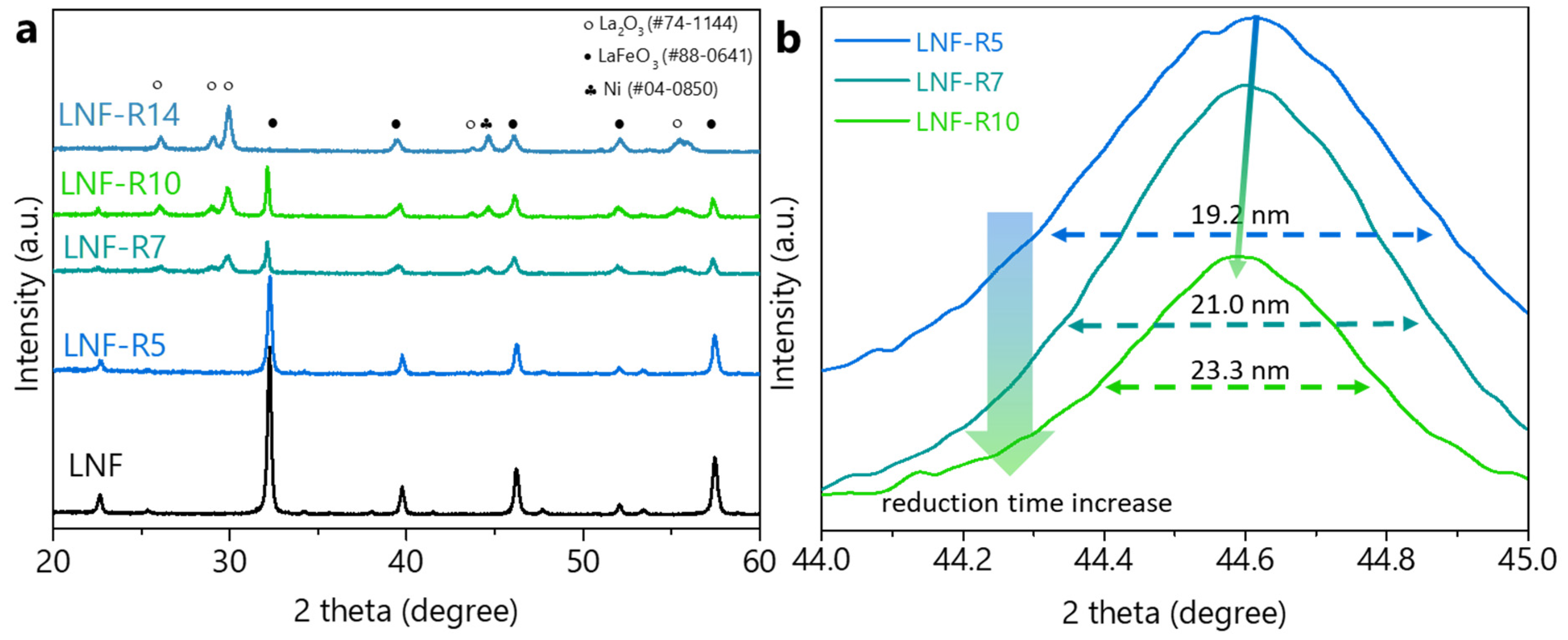
3. Results and Discussion

LNF catalysts were fabricated using a modified sol–gel method. Exsolution treatment was performed at 650 °C in a H2 atmosphere. The exsolution time was increased from 5 to 10 h to assess the change in exsolved nanoparticles (NPs), and the catalysts were denoted as LNF–R5, LNF–R7, and LNF–R10, based on their reduction time. The structural change was first analyzed by XRD analysis (Figure 1a). The structure of the pristine LNF was consistent with that of orthorhombic LaFeO3 perovskite (pdf # 88–0641). After the reduction treatment, the parent perovskite structure was remained for all three samples. In addition, a metal peak appeared between 44.5° and 44.6° (Figure 1b). Since the Ni metal peak (pdf # 45–1027) and Fe metal peak (pdf # 87–0722) are located at 44.520° and 44.764°, respectively, and the location of the emergent peak is closer to that of Ni, the composition is more likely to be Ni than Fe. As the reduction time increased from 5 to 10 h, the metal peak shifted to a lower 2θ. This indicates unit cell volume expansion [17]. When the doped Ni2+ is reduced to Ni0, lattice Fe3+ (ionic radius = 0.645 Å) is also partially reduced to Fe2+ (ionic radius = 0.70 Å), resulting in unit cell expansion. This will be discussed further in relation to the subsequent XPS analysis.
The size of the exsolved NPs can be calculated from the Scherrer formula based on the XRD peaks in Figure 1b. The sizes of LNF–R5, LNF–R7, and LNF–R10 are 19.2, 21.0, and 23.3 nm, respectively. As the reduction time increases from 5 to 10 h, the size of exsolved NPs slightly increases, while the main perovskite oxide structure is maintained. However, the secondary phase, La2O3, begins to appear from 7 h of reduction treatment. As the reduction time increases, the intensity of the La2O3 peaks keeps increasing, and, after 14 h, LNF totally decomposes into La2O3, Fe, and Ni.
The surface morphology of the samples was observed using SEM and HR-TEM (Figure 2). The pristine LNF surface was smooth and dense (Figure 2a,g). However, after reduction treatment of the sample for 5 h, small NPs emerged on the surface, but the dense structure was maintained (Figure 2b,h). With increasing reduction time, more NPs emerged on the surface (Figure 2c–e), and, simultaneously, the parent LNF structure became less dense. Table 1 lists the physical characteristics of the exsolved NPs. As the reduction time increased, the NP size slightly increased. On the other hand, the population of the NPs distinctly increased. The size tendency is in agreement with the XRD results in Figure 1. This observation is also in accordance with the results of Tang et al. [25], who showed that a reduction time of 30 h had no significant effect on the particle size, but the population of the NPs increased by almost three times. Meanwhile, as the reduction time increased, the surface area of the samples increased (Table 1). This was because more exsolved NPs appeared on the LNF–R7 and LNF–R10 surfaces, thus leading to the larger surface areas. Another possible reason for the surface area increase is the formation of La2O3 from the partial decomposition of the LNF perovskite oxide. As a result, after a 5 h reduction treatment, Ni NPs were successfully formed on the surface, without changing the support structure. As the reduction time increased (but remained less than 14 h), more Ni NPs were nucleated, and thus formed on the surface.
The oxidation states of each element were confirmed by XPS measurement. It should be noted that the overlapping of the La 3d3/2 peak and the main Ni 2p peak [26,27] may cause the oxidation states to be inaccurately estimated. Thus, XPS measurements for lanthanum 3d and Ni 2p were not used, while those of Ni 3p were only used to estimate its oxidation states. The oxidation states of oxygen (Figure 3a) were assigned to two species by the binding energy EB: EB = 528.7 eV for lattice oxygen, and EB = 531.3 eV for oxygen vacancies [28]. Before the reduction treatment, the oxygen vacancies were 38.0%, which may be due to the A-site defect [28]. An A-site defect of 0.1 mol caused non-stoichiometry of the surface oxygen, leading to easier exsolution of the doped B-site cation [19]. After the reduction treatment, the oxygen vacancies on the surface increased to ~90.0% for all three samples. There were no obvious differences among these samples, which indicates that the oxygen that can be removed from the lattice was consumed over 5 h. After reduction treatment for 5 h, the relative number of surface oxygen vacancies did not change significantly.
The oxidation states of the nickel were estimated from the evolution of Ni 3p species (Figure 3b). The peaks appeared at 66.0 and 67.5 eV (green- and blue-shaded areas), which are the typical 3p binding energies for Ni0 and Ni2+ in oxides, respectively [26]. In the pristine LNF, Ni2+ was the main peak. As the reduction time increased from 5 to 7 to 10 h, the Ni0 fraction increased from 36.2% to 38.2% to 43.5%, respectively; this change indicated that, as the reduction time increased, more nickel oxide was reduced to metal. A similar tendency for Ni exsolution has previously been reported [26]. This indicates that the nickel in the LNF bulk lattice continuously exsolves to the surface under the reducing environment.
In the Fe 2p binding energy analysis (Figure 3c), peaks were detected at 709.6 and 711.4 eV, which were assigned to Fe2+ and Fe3+, respectively [27,29,30]. The Fe2+ fractions for LNF–R5, LNF–R7, and LNF–R10 are 51.1%, 55.8%, and 57.9%, respectively, which indicates the partial reduction of lattice Fe3+ during exsolution treatment. The increasing Fe2+ fractions results in unit cell volume expansion, and, thus, explains why, in Figure 1b, the metal XRD peak shifted to a lower 2θ. The fraction of Fe metal was 0% for pristine LNF, but the Fe metal peak appeared after the reduction treatment, and as the reduction time increased from 5 to 7 to 10 h, the Fe fraction increased from 3.8% to 4.9% to 11.3%, respectively. This concurs with the results of the XRD and TEM–EDS analyses, which demonstrated that a small amount of Fe was reduced to Fe0 with the reduction treatment, and, on increasing the reduction time, the amount of reduced metals was slightly increased. The XRD, SEM, TEM, and XPS results led to the following two observations: firstly, with the reduction treatment, Ni metal segregates from the bulk lattice, and emerges on the surface to form NPs, without changing the parent perovskite structure; secondly, if the reduction time is longer, it can generate a greater population of NPs. Most of the exsolved NPs are nickel, but a small fraction of iron is also included.
The reducibility difference before and after the exsolution of LNF was monitored by the H2 consumption during the temperature-programmed reduction (H2–TPR) (Figure 4a). LNF had two hydrogen consumption peaks: a small peak at 312 °C caused by surface oxygen reacting with H2, and a large peak at 456 °C caused by the reduction of Ni2+ to Ni0 and the partial reduction of Fe2+ to Fe0 in the bulk. The reduced samples (LNF–R5, LNF–R7, and LNF–R10) did not consume as much hydrogen as the pristine LNF did to form a peak. As reported, the emergence of Ni on the surface occurred after the surface oxygen was consumed by hydrogen [31]. Therefore, the subtle hydrogen consumption peak in LNF–R5, LNF–R7, and LNF–R10 indicates that the oxygen consumption process was already complete before 5 h, and that, after 5 h, it was mainly the nucleation and growth of Ni NPs that occurred under the reduction. The highest temperature reduction peak at >700 °C (not shown in Figure 4a) was assigned to structural changes due to the collapse of the perovskite oxide [32,33,34,35]. The results of H2–TPR for a series of reduction samples provided a possible exsolution process in which the surface oxygen was first reacted with the hydrogen to form sufficient defects of the surface oxygen, followed by the diffusion of the doped Ni to the surface while reducing Ni2+ to Ni0 and forming the NPs. With the longer reduction time, more Ni ions were diffused to the surface, forming metal NPs. This observation is in agreement with the XPS results, and has also been proven by related research involving environmental transmission electron microscopy (ETEM) [31].
The O2–TPD spectra can be used to clarify the surface state of the NPs (Figure 4b). As reported, the oxygen species observed by O2–TPD measurement can be assigned according to the bond strengths between the adsorbed oxygen and the surface species [28]: physically adsorbed oxygen < oxygen species that are located at surface vacancies < surface lattice oxygen [36]. In addition, the desorption of molecular oxygen from Ni metal was reported at 190–360 °C [37]. Therefore, in this study, the peaks appearing at ~350, 350–400, and 400–550 °C can be assigned to oxygen adsorbed onto the exsolved metal, oxygen species that are located at surface vacancies (O2(ad) and O(ad)), and surface lattice oxygen (Olatt2−), respectively [36]. The pristine LNF has one low-intensity peak at 363 °C, which can be assigned to the surface oxygen desorption of O2(ad) and O(ad) species, because the A-site defects led to a slightly unstable perovskite structure with a small number of oxygen vacancies [38]. This can also be confirmed by the above XPS analysis. In contrast, the LNF–R5 sample has a sharp peak at 325 °C, which is assigned to oxygen that had adsorbed onto the metal surface, and another peak at 400 °C, which is assigned to the desorption of surface oxygens, O2(ad) and O(ad) species, which were adsorbed into the oxygen vacancies. Similarly, LNF–R7 and LNF–R10 also have a sharp peak at ~325 °C, and, as the reduction treatment time increases, the peak area increases. The appearance of a sharp peak at ~325 °C for the reduced samples suggests the presence of exsolved NPs, and the peak area indicates that more NPs were exsolved with an increasing reduction time. This agrees with the prediction based on the XRD results and observations of the SEM and TEM images. For LNF–R7, the peak appearing at ~400 °C is similar to the one in LNF–R5. This implies that the oxygen vacancies on the surface of LNF–R7 were similar to those of LNF–R5, which is consistent with the XPS O 1s measurement results. For LNF–R10, the peak appearing at ~400 °C is slightly increased compared to those of LNF-R7 and LNF-R5. This may be caused by the oxygen desorbed from the reduced Fe species [39]. As can be confirmed in the XPS Fe 2p results, the amount of Fe increased from 4.9% (LNF–R7) to 11.3% (LNF–R10). This indicates that the O2–TPD measurement results are consistent with the XPS results.
CO–TPD and CO–TPR were performed to identify the CO adsorption species on the sample surface. The pristine LNF absorbed much less CO than the LNF–Rx did (Figure 4c). Moreover, as the reduction time increased, the area of the main CO desorption peak (at 310 °C) also increased. The good CO adsorption/desorption ability of LNF–Rx might be due to the exsolved Ni metal NPs [40]. Since an optimum CO adsorption/desorption ability can lead to higher CO oxidation ability [41], this also explains why the CO conversion with LNF–Rx is higher than that with the pristine LNF, and the longer reduction time leads to higher CO conversion. Moreover, another CO desorption peak appearing at 400 °C might be caused by the partially reduced Fe metal [42]. As in the XPS results, the Fe metal fraction slightly increased from LNF–R5 to LNF–R7 to LNF–R10, and, thus, the peak area at 400 °C also increased. The CO–TPD results suggest that the CO molecules are mainly adsorbed onto the exsolved Ni NPs, and, as with increasing the reduction time, the Ni NPs increased, and there was more CO adsorbed on and desorbed from the Ni NPs, thus leading to the higher CO conversion.
The CO2 formation signals were collected while CO was continuously provided to the cells for which the temperatures were increasing (Figure 4d). For the pristine LNF, there existed three CO2 formation peaks, which were denoted as α, β, and γ peaks at 464, 705, and 950 °C, respectively. The α peak was formed by the bonding of CO with the surface oxygen on LNF [31] The β peak was assigned to the lattice oxygen that was bonded with Fe2+/Ni2+ [43], which is relatively more difficult to remove than the surface oxygen. The γ peak was assigned to the lattice oxygen that was bonded with Fe3+, which is the most inert, and, thus, only occurred at a much higher temperature. Since the pristine LNF has more surface oxygen than the reduction-treated LNF–Rx samples, CO2 formation on LNF is easier, although LNF–Rx samples have a stronger CO adsorption/desorption ability, as determined by CO–TPD analysis. The α peak was largely decreased for the LNF–Rx samples because, during the exsolution process, the surface oxygen was eliminated. Therefore, when there is no external oxygen source supplied to the system, LNF has a stronger ability to form CO2 than LNF–Rx. It is known that La2O3 is a non-reducible metal oxide [44], which implies that only a small amount of its lattice oxygen is used. Since the La2O3 peak in the XRD pattern was stronger in LNF–R10 than in LNF–R7 and LNF–R5 (Figure 1a), more La2O3 was formed in LNF–R10, and, accordingly, as the reduction time increased, the γ peak decreased.
As discussed above, LNF provides a better CO2 formation ability when there is no external oxygen source to the system, but, as will be discussed in the following WGS activity analysis, LNF–Rx showed much better activity. Since H2O can often be the only external source of oxygen in the WGS reaction, the external oxygen supplied by the dissociation of H2O on the exsolved metal plays an important role in the catalytic activity. Based on the O2–TPD, CO–TPD, and CO–TPR analyses, the exsolved metal was identified as an active site for CO adsorption and oxygen delivery via H2O dissociation.
After the reduction treatment, the CO conversion in the HT–WGS temperature window of 300 to 600 °C [9,45] was significantly increased and, as the reduction time increased, it continuously increased (Figure 5a). The T50 at which CO conversion reaches 50% for LNF, LNF–R5, LNF–R7, and LNF–R10 was 525, 445, 430, and 403 °C, respectively, and, for the HT–WGS commercial catalyst Fe–Cr, the T50 was 458 °C. The increase in the CO conversion of LNF–R5 after exsolution treatment was solely a result of the exsolved Ni NPs because the reduction treatment did not cause any significant structural changes apart from the exsolution of Ni NPs. Further activity improvements for LNF–R7 and LNF–R10 may be caused by an increase in the Ni NPs population, as the secondary phase La2O3 that appeared in LNF–R7 and LNF–R10 was non-reducible [43]. During the catalytic conversion of HT–WGS, the yield of H2 is as important as the CO conversion to avoid the undesirable side reaction of CO/CO2 hydrogenation, forming methane [13,46,47,48]. The H2 yield of LNF–R5, R7, and R10 was much higher than that of the LNF (Figure 5b), so the exsolved NPs also increased the expected H2 production yield for HT–WGS. Similar to the CO conversion, LNF–R10 had the best H2 yield among the reduced samples. The smaller size and denser population of Ni NPs on LNF–R7 and LNF–R10 provide more active sites than the LNF–R5, and, thus, those two samples showed better activity. The catalytic activity results again proved that a longer reduction time can create more nuclei in the exsolved Ni NPs, as more Ni atoms are able to emerge from the deeper bulk of the perovskite oxide. More Ni NPs provide more active sites for the HT–WGS reaction; therefore, with an increasing reduction time, the reduced samples continuously enhance the activity.
In addition to the enhanced catalytic activity, the reduced samples also exhibited good thermal stability during a 50 h long-term stability test at 500 °C (Figure 5c,d). Although LNF–R5 had the lowest activity among the three reduced samples, it showed better long-term stability than the other two samples. After the 50 h HT–WGS reaction, the CO conversion of LNF–R10, LNF–R7, and LNF–R5 decreased by 24.1%, 26.3%, and 23%, respectively. Simultaneously, the H2 yield of LNF–R10, LNF–R7, and LNF–R5 decreased by 13.5%, 14.6%, and 9.4%, respectively. However, LNF–R5 was more stable than the others. During the first 5 h, the CO conversion of LNF–R10 and LNF–R7 decreased by approximately 6.7% and 5.2%, whereas that of LNF–R5 decreased by only 2.2%. The slower decrease in LNF–R5 activity might have been because the parent perovskite oxide remained unchanged. As mentioned in Figure 1, once the parent perovskite oxides are partially decomposed, the catalysts become less resistant to the long-term thermal conditions. The activity and stability of each catalyst is summarized in Table 2. In summary, the activity and stability results demonstrate that the exsolution catalyst not only improved the CO conversion and H2 yield for HT–WGS, but also greatly remedied the shortage of conventional loaded catalysts by preventing the active sites from sintering under a high temperature and extended operation.

4. Conclusions

La0.9Ni0.05Fe0.95O3 catalysts for HT–WGS were fabricated using a modified sol–gel method. Exsolution treatment was performed at 650 °C in a 100% H2 atmosphere. The exsolution time was increased from 5 to 10 h to identify the change in the exsolved NPs. Ni metal NPs were successfully exsolved from the lattice to the perovskite LNF surface upon the reduction treatment. As the reduction time increased, the size of the exsolved NPs did not change significantly, while the main perovskite oxide structure was maintained. However, more Ni particles were nucleated, and, thus, more NPs were formed on the surface. The H2–TPR results provided a prediction that the oxygen-consuming exsolution process had already been completed before 5 h, and, after that, it was mainly the nucleation and growth of Ni NPs that occurred under the reduction. Based on the O2–TPD, CO–TPD, and CO–TPR analyses, exsolved metal has been proven to perform an important function as an active site for CO adsorption and oxygen delivery by dissociating H2O. We believe that our results are helpful toward the understanding of the exsolution process of perovskite oxide, so that more effective thermal-resistant catalysts can be developed.

Author Contributions

Conceptualization, R.H. and J.W.H.; methodology, R.H.; formal analysis, R.H.; investigation, R.H.; writing—original draft preparation, R.H.; writing—review and editing, J.W.H.; visualization, R.H.; supervision, J.W.H.; project administration, J.W.H.; funding acquisition, J.W.H. All authors have read and agreed to the published version of the manuscript.

Funding

The authors acknowledge the financial support from the Basic Science Research Program (NRF-2020M3D3A1A01028935 and NRF-2021M3H7A1026173) through the National Research Foundation of Korea (NRF) grant funded by the Korea government (MSIT). The authors also acknowledge the financial support from the Korea Institute of Energy Technology Evaluation and Planning (20193410100050) in the Ministry of Trade, Industry, and Energy.

Institutional Review Board Statement

Not applicable.

Informed Consent Statement

Not applicable.

Data Availability Statement

Not applicable.

Conflicts of Interest

The authors declare no conflict of interest.

References

  1. Chiriac, R.; Racovitza, A.; Podevin, P.; Descombes, G. On the possibility to reduce CO2 emissions of heat engines fuelled partially with hydrogen produced by waste heat recovery. Int. J. Hydrog. Energy 2015, 40, 15856–15863. [Google Scholar] [CrossRef]
  2. Ebrahimi, P.; Kumar, A.; Khraisheh, M. A review of recent advances in water-gas shift catalysis for hydrogen production. Emergent Mater. 2020, 3, 881–917. [Google Scholar] [CrossRef]
  3. Pal, D.B.; Chand, R.; Upadhyay, S.N.; Mishra, P.K. Performance of water gas shift reaction catalysts: A review. Renew. Sustain. Energy Rev. 2018, 93, 549–565. [Google Scholar] [CrossRef]
  4. Han, S. Biohydrogen production by anaerobic fermentation of food waste. Int. J. Hydrog. Energy 2004, 29, 569–577. [Google Scholar] [CrossRef]
  5. Lay, J.-J.; Lee, Y.-J.; Noike, T. Feasibility of biological hydrogen production from organic fraction of municipal solid waste. Water Res. 1999, 33, 2579–2586. [Google Scholar] [CrossRef]
  6. Mizuno, O.; Dinsdale, R.; Hawkes, F.R.; Hawkes, D.L.; Noike, T. Enhancement of hydrogen production from glucose by nitrogen gas sparging. Bioresour. Technol. 2000, 73, 59–65. [Google Scholar] [CrossRef]
  7. Chen, L.; Qi, Z.; Zhang, S.; Su, J.; Somorjai, G.A. Catalytic Hydrogen Production from Methane: A Review on Recent Progress and Prospect. Catalysts 2020, 10, 858. [Google Scholar] [CrossRef]
  8. Hairuddin, A.A.; Yusaf, T.; Wandel, A.P. A review of hydrogen and natural gas addition in diesel HCCI engines. Renew. Sustain. Energy Rev. 2014, 32, 739–761. [Google Scholar] [CrossRef] [Green Version]
  9. Maneerung, T.; Hidajat, K.; Kawi, S. K-doped LaNiO3 perovskite for high-temperature water-gas shift of reformate gas: Role of potassium on suppressing methanation. Int. J. Hydrog. Energy 2017, 42, 9840–9857. [Google Scholar] [CrossRef]
  10. Jha, A.; Jeong, D.-W.; Lee, Y.-L.; Jang, W.-J.; Shim, J.-O.; Jeon, K.-W.; Rode, C.V.; Roh, H.-S. Chromium free high temperature water–gas shift catalyst for the production of hydrogen from waste derived synthesis gas. Appl. Catal. A Gen. 2016, 522, 21–31. [Google Scholar] [CrossRef]
  11. Meshkani, F.; Rezaei, M. Hydrogen production by high temperature water gas shift reaction over highly active and stable chromium free Fe-Al-Ni catalysts. Int. J. Hydrog. Energy 2015, 40, 10867–10875. [Google Scholar] [CrossRef]
  12. Ramírez Reina, T.; González Castaño, M.; Palma, S.; Ivanova, S.; Odriozola, J.A. Heterogeneous Gold Catalysts and Catalysis; The Royal Society of Chemistry: London, UK, 2014; pp. 111–139. [Google Scholar]
  13. Ashok, J.; Wai, M.H.; Kawi, S. Nickel-based Catalysts for High-temperature Water Gas Shift Reaction-Methane Suppression. ChemCatChem 2018, 10, 3927–3942. [Google Scholar] [CrossRef]
  14. Kim, J.H.; Kim, J.K.; Liu, J.; Curcio, A.; Jang, J.-S.; Kim, I.-D.; Ciucci, F.; Jung, W. Nanoparticle Ex-solution for Supported Catalysts: Materials Design, Mechanism and Future Perspectives. ACS Nano 2021, 15, 81–110. [Google Scholar] [CrossRef] [PubMed]
  15. Neagu, D.; Oh, T.-S.; Miller, D.N.; Ménard, H.; Bukhari, S.M.; Gamble, S.R.; Gorte, R.J.; Vohs, J.M.; Irvine, J.T.S. Nano-socketed nickel particles with enhanced coking resistance grown in situ by redox exsolution. Nat. Commun. 2015, 6, 8120. [Google Scholar] [CrossRef] [PubMed] [Green Version]
  16. Yentekakis, I.V.; Goula, G.; Hatzisymeon, M.; Betsi-Argyropoulou, I.; Botzolaki, G.; Kousi, K.; Kondarides, D.I.; Taylor, M.J.; Parlett, C.M.A.; Osatiashtiani, A.; et al. Effect of support oxygen storage capacity on the catalytic performance of Rh nanoparticles for CO2 reforming of methane. Appl. Catal. B Environ. 2019, 243, 490–501. [Google Scholar] [CrossRef] [Green Version]
  17. Papargyriou, D.; Miller, D.N.; Sirr Irvine, J.T. Exsolution of Fe-Ni alloy nanoparticles from (La,Sr)(Cr,Fe,Ni)O3 perovskites as potential oxygen transport membrane catalysts for methane reforming. J. Mater. Chem. A 2019, 7, 15812–15822. [Google Scholar] [CrossRef]
  18. Jang, W.-J.; Shim, J.-O.; Jeon, K.-W.; Na, H.-S.; Kim, H.-M.; Lee, Y.-L.; Roh, H.-S.; Jeong, D.-W. Design and scale-up of a Cr-free Fe-Al-Cu catalyst for hydrogen production from waste-derived synthesis gas. Appl. Catal. B Environ. 2019, 249, 72–81. [Google Scholar] [CrossRef]
  19. Nishihata, Y.; Mizuki, J.; Akao, T.; Tanaka, H.; Uenishi, M.; Kimura, M.; Okamoto, T.; Hamada, N. Self-regeneration of a Pd-perovskite catalyst for automotive emissions control. Nature 2002, 418, 164–167. [Google Scholar] [CrossRef] [PubMed]
  20. Neagu, D.; Tsekouras, G.; Miller, D.N.; Ménard, H.; Irvine, J.T.S. In situ growth of nanoparticles through control of non-stoichiometry. Nat. Chem. 2013, 5, 916–923. [Google Scholar] [CrossRef] [Green Version]
  21. Sun, Y.-F.; Li, J.-H.; Cui, L.; Hua, B.; Cui, S.-H.; Li, J.; Luo, J.-L. A-site-deficiency facilitated in situ growth of bimetallic Ni–Fe nano-alloys: A novel coking-tolerant fuel cell anode catalyst. Nanoscale 2015, 7, 11173–11181. [Google Scholar] [CrossRef]
  22. Kwon, O.; Sengodan, S.; Kim, K.; Kim, G.; Jeong, H.Y.; Shin, J.; Ju, Y.W.; Han, J.W.; Kim, G. Exsolution trends and co-segregation aspects of self-grown catalyst nanoparticles in perovskites. Nat. Commun. 2018, 8, 15967. [Google Scholar] [CrossRef] [Green Version]
  23. Zhang, J.; Gao, M.-R.; Luo, J.-L. In Situ Exsolved Metal Nanoparticles: A Smart Approach for Optimization of Catalysts. Chem. Mater. 2020, 32, 5424–5441. [Google Scholar] [CrossRef]
  24. Gao, Y.; Chen, D.; Saccoccio, M.; Lu, Z.; Ciucci, F. From material design to mechanism study: Nanoscale Ni exsolution on a highly active A-site deficient anode material for solid oxide fuel cells. Nano Energy 2016, 27, 499–508. [Google Scholar] [CrossRef]
  25. Tang, C.; Kousi, K.; Neagu, D.; Portolés, J.; Papaioannou, E.I.; Metcalfe, I.S. Towards efficient use of noble metals via exsolution exemplified for CO oxidation. Nanoscale 2019, 11, 16935–16944. [Google Scholar] [CrossRef] [PubMed]
  26. Opitz, A.K.; Nenning, A.; Rameshan, C.; Kubicek, M.; Götsch, T.; Blume, R.; Hävecker, M.; Knop-Gericke, A.; Rupprechter, G.; Klötzer, B.; et al. Surface Chemistry of Perovskite-Type Electrodes during High Temperature CO2 Electrolysis Investigated by Operando Photoelectron Spectroscopy. ACS Appl. Mater. Interfaces 2017, 9, 35847–35860. [Google Scholar] [CrossRef] [PubMed]
  27. Celorrio, V.; Dann, E.; Calvillo, L.; Morgan, D.J.; Hall, S.R.; Fermin, D.J. Oxygen Reduction at Carbon-Supported Lanthanides: The Role of the B-Site. ChemElectroChem 2016, 3, 283–291. [Google Scholar] [CrossRef] [Green Version]
  28. Yang, J.; Hu, S.; Fang, Y.; Hoang, S.; Li, L.; Yang, W.; Liang, Z.; Wu, J.; Hu, J.; Xiao, W.; et al. Oxygen Vacancy Promoted O2 Activation over Perovskite Oxide for Low-Temperature CO Oxidation. ACS Catal. 2019, 9, 9751–9763. [Google Scholar] [CrossRef]
  29. Moulder, J.F.; Stickle, W.F.; Sobol, P.E.; Bomben, K.D. Handbook of X-ray Photoelectron Spectroscopy; Physical Electronics, Inc.: Eden Praire, MN, USA, 1995. [Google Scholar]
  30. Ha, M.N.; Lu, G.; Liu, Z.; Wang, L.; Zhao, Z. 3DOM-LaSrCoFeO6–δ as a highly active catalyst for the thermal and photothermal reduction of CO2 with H2O to CH4. J. Mater. Chem. A 2016, 4, 13155–13165. [Google Scholar] [CrossRef]
  31. Deka, D.J.; Kim, J.; Gunduz, S.; Aouine, M.; Millet, J.-M.M.; Co, A.C.; Ozkan, U.S. Investigation of Hetero-phases Grown via In-situ Exsolution on a Ni-doped (La,Sr)FeO3 Cathode and the Resultant Activity Enhancement in CO2 Reduction. Appl. Catal. B Environ. 2021, 285, 119917. [Google Scholar] [CrossRef]
  32. Steiger, P.; Delmelle, R.; Foppiano, D.; Holzer, L.; Heel, A.; Nachtegaal, M.; Kröcher, O.; Ferri, D. Structural Reversibility and Nickel Particle stability in Lanthanum Iron Nickel Perovskite-Type Catalysts. ChemSusChem 2017, 10, 2505–2517. [Google Scholar] [CrossRef]
  33. Nakamura, T.; Petzow, G.; Gauckler, L.J. Stability of the perovskite phase LaBO3 (B = V, Cr, Mn, Fe, Co, Ni) in reducing atmosphere. Mater. Res. Bull. 1979, 14, 649–659. [Google Scholar] [CrossRef]
  34. Crespin, M.; Levitz, P.; Gatineau, L. Reduced forms of LaNiO3 perovskite. Part 1—Evidence for new phases: La2Ni2O5 and LaNiO2. J. Chem. Soc. Faraday Trans. 2 1983, 79, 1181–1194. [Google Scholar] [CrossRef]
  35. Koponen, M.J.; Suvanto, M.; Kallinen, K.; Kinnunen, T.-J.J.; Härkönen, M.; Pakkanen, T.A. Structural transformations in cubic structure of Mn/Co perovskites in reducing and oxidizing atmospheres. Solid State Sci. 2006, 8, 450–456. [Google Scholar] [CrossRef]
  36. Zheng, Y.; Wang, W.; Jiang, D.; Zhang, L.; Li, X.; Wang, Z. Ultrathin mesoporous Co3O4 nanosheets with excellent photo-/thermo-catalytic activity. J. Mater. Chem. A 2016, 4, 105–112. [Google Scholar] [CrossRef]
  37. Wu, S.-L.; Kuo, J.-H.; Wey, M.-Y. Design of catalysts comprising a nickel core and ceria shell for hydrogen production from plastic waste gasification: An integrated test for anti-coking and catalytic performance. Catal. Sci. Technol. 2020, 10, 3975–3984. [Google Scholar] [CrossRef]
  38. Wang, X.; Zhang, Y.; Li, Q.; Wang, Z.; Zhang, Z. Identification of active oxygen species for soot combustion on LaMnO3 perovskite. Catal. Sci. Technol. 2012, 2, 1822–1824. [Google Scholar] [CrossRef]
  39. Iwamoto, M.; Yoda, Y.; Yamazoe, N.; Seiyama, T. Study of metal oxide catalysts by temperature programmed desorption. 4. Oxygen adsorption on various metal oxides. J. Phys. Chem. 1978, 82, 2564–2570. [Google Scholar] [CrossRef]
  40. Papaioannou, E.I.; Neagu, D.; Ramli, W.K.W.; Irvine, J.T.S.; Metcalfe, I.S. Sulfur-Tolerant, Exsolved Fe–Ni Alloy Nanoparticles for CO Oxidation. Top. Catal. 2018, 62, 1149–1156. [Google Scholar] [CrossRef] [Green Version]
  41. Huang, R.; Kim, K.; Kim, H.J.; Jang, M.G.; Han, J.W. Size-Controlled Pd Nanoparticles Loaded on Co3O4 Nanoparticles by Calcination for Enhanced CO Oxidation. ACS Appl. Nano Mater. 2019, 3, 486–495. [Google Scholar] [CrossRef] [Green Version]
  42. Tian, Z.; Wang, C.; Yue, J.; Zhang, X.; Ma, L. Effect of a potassium promoter on the Fischer-Tropsch synthesis of light olefins over iron carbide catalysts encapsulated in graphene-like carbon. Catal. Sci. Technol. 2019, 9, 2728–2741. [Google Scholar] [CrossRef]
  43. Pendyala, V.R.R.; Graham, U.M.; Jacobs, G.; Hamdeh, H.H.; Davis, B.H. Fischer-Tropsch Synthesis: Deactivation as a Function of Potassium Promoter Loading for Precipitated Iron Catalyst. Catal. Lett. 2014, 144, 1704–1716. [Google Scholar] [CrossRef]
  44. Pandey, A.; Jain, G.; Vyas, D.; Irusta, S.; Sharma, S. Nonreducible, Basic La2O3 to Reducible, Acidic La2–xSbxO3 with Significant Oxygen Storage Capacity, Lower Band Gap, and Effect on the Catalytic Activity. J. Phys. Chem. C 2017, 121, 481–489. [Google Scholar] [CrossRef]
  45. Thalinger, R.; Opitz, A.K.; Kogler, S.; Heggen, M.; Stroppa, D.; Schmidmair, D.; Tappert, R.; Fleig, J.; Klötzer, B.; Penner, S. Water-Gas Shift and Methane Reactivity on Reducible Perovskite-Type Oxides. J. Phys. Chem. C 2015, 119, 11739–11753. [Google Scholar] [CrossRef] [Green Version]
  46. Sehested, J.; Dahl, S.; Jacobsen, J.; Rostrup-Nielsen, J.R. Methanation of CO over Nickel:  Mechanism and Kinetics at High H2/CO Ratios. J. Phys. Chem. B 2005, 109, 2432–2438. [Google Scholar] [CrossRef]
  47. Senanayake, S.D.; Evans, J.; Agnoli, S.; Barrio, L.; Chen, T.-L.; Hrbek, J.; Rodriguez, J.A. Water-Gas Shift and CO Methanation Reactions over Ni–CeO2(111) Catalysts. Top. Catal. 2011, 54, 34–41. [Google Scholar] [CrossRef]
  48. Roiaz, M.; Monachino, E.; Dri, C.; Greiner, M.; Knop-Gericke, A.; Schlögl, R.; Comelli, G.; Vesselli, E. Reverse Water-Gas Shift or Sabatier Methanation on Ni(110)? Stable Surface Species at Near-Ambient Pressure. J. Am. Chem. Soc. 2016, 138, 4146–4154. [Google Scholar] [CrossRef]
Figure 1. Powder sample characterization. (a) X-ray diffraction patterns of LNF before and after reduction for 5, 7, 10, and 14 h; (b) 2 theta from 44° to 45°.
Chemengineering 05 00028 g001
Figure 2. Scanning electron microscopy (SEM) images of LNF samples: (a) LNF; (b) LNF–R5; (c) LNF–R7; (d,e) LNF–R10; (f) LNF–R14; High-resolution transmission electron microscopy (HR-TEM) images of LNF samples: (g) LNF; (h) LNF–R5; (i) LNF–R7; (j) LNF–R10.
Chemengineering 05 00028 g002
Figure 3. XPS analysis of the LNF samples (a) O 1s, (b) Ni 3p, and (c) Fe 2p for each sample.
Chemengineering 05 00028 g003
Figure 4. Temperature-programmed measurements of LNF samples before and after exsolution treatment with different reduction times. (a) H2–TPR; (b) O2–TPD; (c) CO–TPD; (d) CO–TPR.
Chemengineering 05 00028 g004
Figure 5. WGS activity for LNF samples with different exsolution treatment times. (a) CO conversion for WGS; (b) H2 yield for WGS; long-term stability of (c) CO conversion; (d) H2 yield comparison. Reaction conditions: 30 mg of catalyst, 100 sccm of total flow (1 sccm CO and 23 sccm H2O vapor balanced with Ar) at GHSV = 146,000 mL/(h·gcat). Long-term stability reaction conditions: GHSV = 146,000 mL/(h·gcat) at 500 °C for 50 h.
Chemengineering 05 00028 g005
Table 1. Physical characteristics of the reduction-treated LNF samples.
Reduction TimeSurface AreaNP Size 1NP Size 2NP Population 3
(h)(10–1 cm2/g)(nm)(nm)(μm–2)
53.319.719.232.6
74.920.521.044.3
108.323.623.351.6
Note: 1 Nanoparticle size is calculated from the Scherrer formula based on the XRD measurement; 2 Nanoparticle size is statistically analyzed using the ImageJ program based on the SEM images; 3 The population of the NPs per um2 is calculated by the ImageJ program based on the SEM images.
Table 2. Catalytic activity and stability of the reduction treated LNF samples.
SampleNi0/(Ni0 + Ni2+)T50 1Xco Decreased 2
(%)(°C)(%)
LNF–R536.244523.0
LNF–R738.243026.3
LNF–R1043.540324.1
Note: 1 “T50” represents the temperature that 50% of CO is converted to CO2. 2 “Xco decreased” represents the CO conversion decreased ratio during 50 h stability test.
Publisher’s Note: MDPI stays neutral with regard to jurisdictional claims in published maps and institutional affiliations.

