Article

Alkali-Activated Adsorbents from Slags: Column Adsorption and Regeneration Study for Nickel(II) Removal

1
Research Unit of Sustainable Chemistry, University of Oulu, P.O. Box 4300, 90570 Oulu, Finland
2
Unit of Applied Chemistry, Kokkola University Consortium Chydenius, University of Jyvaskylä, Talonpojankatu 2B, FI-67100 Kokkola, Finland
*
Author to whom correspondence should be addressed.
ChemEngineering 2021, 5(1), 13; https://doi.org/10.3390/chemengineering5010013
Submission received: 5 February 2021 / Revised: 23 February 2021 / Accepted: 1 March 2021 / Published: 5 March 2021

Abstract

:
Alkali-activated adsorbents were synthesized by mixing three different slags from the steel industry: blast furnace slag (BFS), ladle slag (LS), and Lintz–Donawitz converter slag (LD). These powdered slag-based geopolymers (GP) were used to remove nickel(II) from aqueous solutions in fixed-bed column studies. The experiments were conducted in pH 6 using a phosphate buffer with initial nickel(II) concentration of 50 mg/L. Samples were taken at time intervals of between 5 and 90 min. Three adsorption–desorption cycles were implemented with a flow rate of 5 mL/min. The geopolymers were characterized by Fourier-Transform Infrared Spectroscopy (FTIR), X-ray powder diffraction (XRD), Field Emission Scanning Electron Microscopy (FESEM), X-ray fluorescence (XRF), specific surface area measurements, and a leaching test. The data were found to describe the Thomas, Adams–Bohart, and Yoon–Nelson models well. For GP (BFS, LS), experimental adsorption capacity was 2.92 mg/g, and for GP (LD, BFS, LS), it was 1.34 mg/g. The results indicated that the produced adsorbents have the potential to be used as adsorbents for the removal of nickel(II).

1. Introduction

The growth of an industrial society depends on water. However, untreated industrial wastewater is harmful to the environment as it includes substances such as heavy metals. Heavy metal in wastewater is caused by various industrial sectors, including battery industry, electroplating, and printed circuit board manufacturing companies [1]. The toxicity of heavy metals can endanger life forms; thus, it is essential to remove them to avoid damaging the environment [2]. However, the methods used for removing heavy metals out of wastewater (such as chemical precipitation, ion exchange, reverse osmosis, and solvent extraction) have some disadvantages, including high investment and operational costs and the ensuing disposal of residual metal sludges [3]. Due to its simplicity and effectiveness, adsorption has recently become a popular research approach in wastewater treatment. It is a suitable technology for use in the removal of heavy metals such as chromium (Cr), cadmium (Cd), lead (Pb), zinc (Zn), copper (Cu), nickel (Ni), arsenic (As), and mercury (Hg) [1,3,4,5,6,7].
In addition to virgin materials, industrial by-products have potential to be used as a raw material for low-cost adsorbents that can be used for the remediation of heavy metal-contaminated wastewaters. In optimum cases, these materials require only minor processing to enhance their adsorptive capacities. Due to their abundance, availability, and high performance, they are considered better alternatives than the most common adsorbent, activated carbon [3]. Due to their porous structure and low cost, alkali-activated adsorbents are currently being widely applied for wastewater treatment. Moreover, alkali-activated materials have great potential to be used as commercial adsorbents [8,9,10,11].
Alkali-activated adsorbents are abbreviated to geopolymers in this paper, even though the structure and formation may not be fully geopolymerized. Geopolymers are basically inorganic polymer materials derived from the alkali activation of aluminosilicate materials, such as fly ash [12], blast furnace slag (BFS) [13], metakaolin [14], Lintz–Donawitz converter slag (LD) [15], and granulated blast furnace slag [16]. Commonly used alkali activators in the synthesis of geopolymers include sodium and potassium hydroxide or sodium and potassium silicate [17]. Alkali-activated materials produced from industrial side streams are a cost-effective solution for the adsorption of heavy metals such as Cd, Ni, boron (B), fluoride (F-), phosphate (PO4−3), NOx, and dyes [18]. Alkali-activated materials have a heterogeneous microstructure, amorphous structure, and possess good surface properties for adsorption. In wastewater purification process, the structure of the porous, adjustable nature and the negative charge on aluminum play an important role [1,2,19]. The capacity of alkali-activated materials to attract cations is due to the presence of charge imbalance caused by aluminum in the structure [2].
In this paper, the nickel removal over industrial by-product-based adsorbents is studied. Nickel is a heavy metal with several effects on human health because it causes chronic bronchitis, reduced lung function, and cancer of the lungs. Moreover, the extensive industrial use of nickel means that a considerable amount of it can enter the aquatic life environment through wastewater discharge. If nickel levels are above the permissible range, its ingestion is associated with the inhibition of oxidative enzyme activity, which can cause several issues to life forms [16,20,21,22]. Industrial activities such as electronics equipment manufacturing and metal cleaning often discharge high concentrations of nickel ions into the wastewater, causing serious water pollution. Since the presence of nickel ions above critical levels may affect the life forms, it is essential that they are removed [23].
Currently, a limited number of studies have addressed the use of alkali-activated materials for nickel(II) removal from aqueous solutions [13,14]. Accordingly, this research investigates the removal of nickel(II) from wastewater using an alkali-activated adsorbent and the column method. There is also a lack of study in the area of using slags from the steel industry (especially ones other than blast furnace slag) for geopolymerization. However, this study fulfills these knowledge gaps. In addition, many adsorption studies on the removal of metals have been performed using batch experiments [12,24]. In this study, the experiments in column have been implemented. This is advantageous because the scalability of results to a larger scale is easier than with batch experiments. Different raw materials intended to be used to prepare geopolymers, including the optimization of the preparation steps and the usage of the produced adsorbents for nickel(II) ions, have been studied in this research.
To characterize the adsorbent, X-ray fluorescence (XRF), X-ray powder diffraction (XRD), Field Emission Scanning Electron Microscope (FESEM), Brunauer–Emmett–Teller (BET), Fourier transform infrared spectra (FTIR), and leaching tests were used. Kinetic models suitable for column studies were applied. This research aims to propose a cost-effective, environment-friendly, and efficient material for separating nickel(II) from aqueous solutions using slag-based alkali-activated adsorbents, resulting in the purification of wastewater. Three cycles of adsorption and desorption regeneration were performed for the reusability of the packed column.

2. Materials and Methods

2.1. Materials

Blast furnace slag (BFS), ladle slag (LS), and Lintz–Donawitz converter slag (LD), obtained from a SSAB Europe’s production site located in Raahe, Finland, were used as raw materials for geopolymerization. BFS is a by-product of smelting iron in a blast furnace, LD slag is generated in a Lintz–Donawitz converter in steel plants, and ladle slag (LS) is formed during the ladle treatment process stage in steel plants during smelting. The detailed compositions of these raw materials are presented in the Results and Discussion Sections.
For the synthesis of geopolymer, sodium silicate (VWR International, Radnor, PA, USA) and Sodium hydroxide (VWR International) were used, and sodium hydroxide solution (FF Chemicals, Werkendam, The Netherland) and hydrochloric acid solution (FF Chemicals) were used to adjust the pH value. Nickel(II) sulfate hexahydrate (Merck, Kenilworth, NJ, USA) was used in the preparation of synthetic wastewater, nitric acid (Merck) was used for acid washing of glassware, and a phosphate buffer (FF chemicals) was used to maintain the pH range.

2.2. Synthesis of Geopolymer (GP)

The BFS, LS, and LD slags were sieved to a particle size of <l mm. The alkaline solution was prepared by mixing sodium silicate solution with 10M sodium hydroxide using a 1:1 weight ratio over the duration of 24 h by shaking in a magnetic stirrer. To form colloid paste, the powdered slag mixtures (<1 mm) with 1:1 weight ratio were mixed along with an alkaline solution with 3:2 weight ratio and then the prepared colloid was discharged into a polyethylene silicon mold and kept at room temperature for 3 days. Slag-based geopolymer was crushed using a jaw crusher and sieved to <0.150 mm. The sieved geopolymer was then washed with distilled water to remove excess alkaline solution and dried in an oven at 105 °C for 24 h. GP (BFS, LS) was prepared by mixing powdered blast furnace slag and ladle slag w/w 1:1 with alkaline solution w/w 3:2, and GP (LD, BFS, LS) was prepared by mixing powdered LD slag, BFS, and LS slag w/w 1:2:1 with alkaline solution w/w 3:2.

2.3. Methods of Characterization

Surface areas were determined by a BET isotherm (Micromeritics ASAP 2020 instrument). The bonding behavior and surface analysis were analyzed by FTIR using a Perkin Elmer Spectrum One spectrometer. The microstructure and external surface were analyzed by a Zeiss Sigma FESEM at the Centre for Material Analysis in the University of Oulu. Elemental composition was determined by using an XRF spectrometer (PANalytical Axios mAX) and nickel concentrations were analyzed by using Atomic absorption spectroscopy (PerkinElmer A Analyst 200, Waltham, MA, USA). The powdered diffraction patterns were analyzed by a PANalytical X’pert Pro X-ray diffractometer using monochromatic CuKα1 radiation (λ = 1.5406 Å) at 45 kV and 40 mA. The diffractograms were collected in the 2θ range of 10° to 85° at 0.017° intervals and with a scan step time of 90 s. The crystalline phases and structures were analyzed by HighScore Plus software. Chemical stability was studied using a leaching test, performed with a ratio of 1:10 using slag-based geopolymer and distilled water. The stabilities of the geopolymers were estimated by measuring the pH value and conductivity with different shaking time intervals from 30 min to 24 h.

2.4. Nickel(II) Removal with Powdered Slag-Based Geopolymer: Column Experiments

The fixed-bed column was designed by using a plastic column (height: 7 cm, inner diameter: 3.3 cm) connected with a peristaltic pump (Watson–Marlow 120 Series). A plastic sieve was placed at the bottom of the column. A thin layer of glass wool and 5 g of acid-washed fine sand was placed on the sieve to avoid any loss of adsorbents. Three grams of fine (<0.150 mm) adsorbent was used in the column experiments. Further, 12 g of acid-washed fine sand and 58 g of acid-washed normal sand were used before and after the adsorbent layers. To avoid chemical precipitation, pH 6 was used in the pretest, which was found to be optimum compared to pH 2 and 4. Synthetic nickel(II) solution with a concentration of 50 mg/L was prepared from 1 g/L stock solution by diluting with phosphate buffer solution to maintain the pH at 6 during adsorption experiments.
Nickel(II) concentrations were analyzed by using atomic absorption spectroscopy, and the samples were taken before and after experiments and within different time intervals. The experiment was stopped after 90 min, and the column was washed with distilled water. Regeneration experiments were conducted using the mixture of 0.2 M of NaCl and 0.1 M NaOH with a weight ratio 3:1 (w/w) using the same flow rate of 5 mL/min as in the first cycle. After regeneration, the column was also washed with distilled water. Three adsorption–regeneration cycles were completed.
The adsorption column capacity is qtotal (mg), and Cad (Cad = C0Ct) (mg/L) is the outflow time (t, min), in which C0 and Ct represent the initial and final concentration values of the nickel(II) solution, respectively.
These values are calculated using Equation (1) as follows:
q t o t a l   =   Q A 1000   =   Q 1000 t = 0 t = t t o t a l C a d   d t
In Equation (1), ttotal refers to the total residual time (min), Q to the outflow rate (mL/min), and the area below the breakthrough curve is referred to as A. The equilibrium metal uptake in the column which shows the saturation loading capacity of the used adsorbent bed, qeq (mg/g), can be calculated by Equation (2) as follows:
q e q = q t o t a l m ,
where m is the total dry weight (g) of slag-based geopolymer GP (BFS, LS) or GP (LD, BFS, LS) in the column.

2.5. Kinetic Models

For an effective column adsorption process, it is necessary to predict the concentration–time profile or breakthrough curve for effluent parameters. However, few mathematical models have been developed for use in the design of continuous fixed adsorption columns. To predict the breakthrough curve behavior, Adams–Bohart, Thomas, and Yoon–Nelson models were applied in this work.

2.5.1. Adams–Bohart Model

The Adams–Bohart model was used to formulate the equation which shows the relation between C t C 0 and t in a flowing system, which was done for the adsorption of chlorine on charcoal. The Adams–Bohart model assumes that both the adsorbing species’ concentration and the adsorbent’s residual capacity are proportional to the rate of the adsorption [25]. To calculate the initial part of the breakthrough curve, the Adams–Bohart model is used and the observed mass transfer rates comply with the following Equation (3):
ln C t C 0 = k A B C 0 t k A B N 0 Z F .
In Equation (3), kAB refers to the kinetic constant (L/mg min), F indicates the linear flow rate (cm/min), N0 is the saturation unit (mg/L), and Z refers to bed height (cm). Terms C0 and Ct are the inlet and effluent nickel(II) ion concentrations (mg/L), respectively. This model is widely used to predict adsorption in a column system and is based on the surface-reaction-rate theory [21,26].

2.5.2. Thomas Model

The Thomas model is used for column adsorption processes to determine the breakthrough curve of the outflow. This also requires the maximum adsorption capacity of an adsorbent. The Thomas model can be expressed in the following equation:
ln C 0 C t 1 = k T h q 0 w Q k T h C 0 t .
In Equation (4), kTh (L/min mg) is the kinetic coefficient and q0 (mg/g) is the adsorption capacity of the bed. The adsorption capacity of the bed at a given flow rate can be calculated from a plot of ln[(C0/Ct) − 1] against t [27]. This model has the assumption of Langmuir kinetics of adsorption–desorption and it is a widely used method in column performance theory. The driving force rate complies with the second-order reversible reaction kinetics and adsorption does not have any axial dispersion derived. Generally, adsorption is not limited by chemical reaction kinetics. However, it is frequently controlled by interphase mass transfer. This issue can result in some errors when this method is used to model adsorption processes [21,26].

2.5.3. Yoon and Nelson Model

The Yoon and Nelson model is used to investigate the breakthrough behavior of adsorbate on adsorbent. This model assumes that the probability of the adsorbate breakthrough on the adsorbent and the adsorbate adsorption are proportional to the rate of the decrease in the probability of adsorption of each adsorbate molecule [28]. This model is less complicated than the other models and needs no detailed data, such as the adsorbate characteristics or adsorbent’s type or properties of the adsorption bed. The following shows the equation for a single component system in the Yoon and Nelson model:
ln C t C 0 C t = k Y N t τ k Y N ,
where kYN refers to the rate constant (L/min) and τ shows the time required for 50% of the adsorbate breakthrough (min), and t is the breakthrough time (min). The Yoon–Nelson model does not require the characteristics of the adsorbate and adsorbent or the parameters of the column system [21,26].

3. Results and Discussion

3.1. Characteristics of Slag-Based Geopolymers

Table 1 presents the elemental compositions of the raw materials of BFS, LS, and LD slags, as analyzed by XRF. The components of all the slags were mainly calcium oxide, aluminum oxide, magnesium oxide, and silica.
The ratio of aluminosilicates (Al2O3 and SiO2) affects the geopolymerization [29,30,31]. Since LD slag contains low amounts of aluminum and some amount of silicon, and LS slag contains much aluminum and some amount of silicon, BFS slag needs to be mixed for geopolymers to justify the Si/Al ratio so that the amount of silicon is higher compared to aluminum. The main components confirm the suitability of raw materials for geopolymer production. The specific BET surface areas were obtained as 33 and 69.5 m2/g for GP (BFS, LS) and GP (LD, BFS, LS), respectively. Geopolymers typically act as ion exchangers, in which the specific surface area does not play an important role. However, these results indicate that the material surface area is also enabling adsorption in addition to ion exchange. Luukkonen et al. (2016) [13] reported specific surface area of 64.5 m2/g for BFS-based geopolymer and 22.4 m2/g for metakaolin-based geopolymer. Sarkar et al. (2017) [15] reported specific surface area of 30.84 m2/g for geopolymer prepared from LD slag. Mácová et al. (2020) [32] reported 19.8 m2/g total pore area for metakaolin-based geopolymers. Therefore, the surface area of sample prepared in this study, GP (LD, BFS, LS), was higher than the surface area of geopolymers presented in the literature. Further, the surface area of the sample GP (BFS, LS) prepared in this study was higher compared with metakaolin-based geopolymers but lower than BFS-based geopolymer. There is a variation in the surface area of the geopolymer depending on whether it is slag- or mixed slag-based. The higher surface area and pore volume of the geopolymer resulted in a variation of adsorption capacity [19,33].
The X-ray diffraction patterns of raw materials LD slag, LS slag, and BFS are presented in Figure 1. The observed peaks were identified in the crystalline phase according to the International Centre for Diffraction Data (ICDD) (PDF-4+ 2020) using the HighScore Plus program in the raw materials of the LS, LD slag, and BFS. From Figure 1, the XRD pattern of LD slag, the peaks with most higher intensities at 2θ of 18.0°, 28.6°, 34.0°, 47.1°, 50.7°, 54.3°, 64.17°, and 71.68° were matched with the portlandite Ca(OH)2 (ICDD 00-004-0733). Peaks with 2θ of 29.3° and 42.80° were matched with calcite CaCO3 (ICDD 04-007-8659). Peaks with 2θ of 32.4° and 41.03° were matched with calcium silicate Ca2SiO4 (ICDD 00-006-0476). The peaks with 2θ of 33.4° and 46.6° were matched with calcium magnesium iron silicate Ca2Fe1.2Mg0.4Si0.4O5 (ICDD 00-045-0571). The small peak at 2θ of 30.9° matched with ankerite (ICDD 00-012-0088). For LS slag, the katoite (CaO)3Al2O3(H2O)6 (ICDD 01-072-1109), calcio-olivine Ca2SiO4 (ICDD 00-049-1672), grossular Ca3Al2((SiO4)1.8(O4H4)1.2) (ICDD 01-083-7409), and strδtlingite Ca2Al2SiO7·8H2O (ICDD 00-029-0285) were identified according to the HighScore analysis. The XRD pattern of BFS showed that mainly amorphous structure is presented because there is a broad halo at the 2θ of 20–40°, which is typical for amorphous. When checking the halo closely, one can find a tiny peak at 2θ of 29.3° which matched CaCO3 (ICDD 01-071-3699).
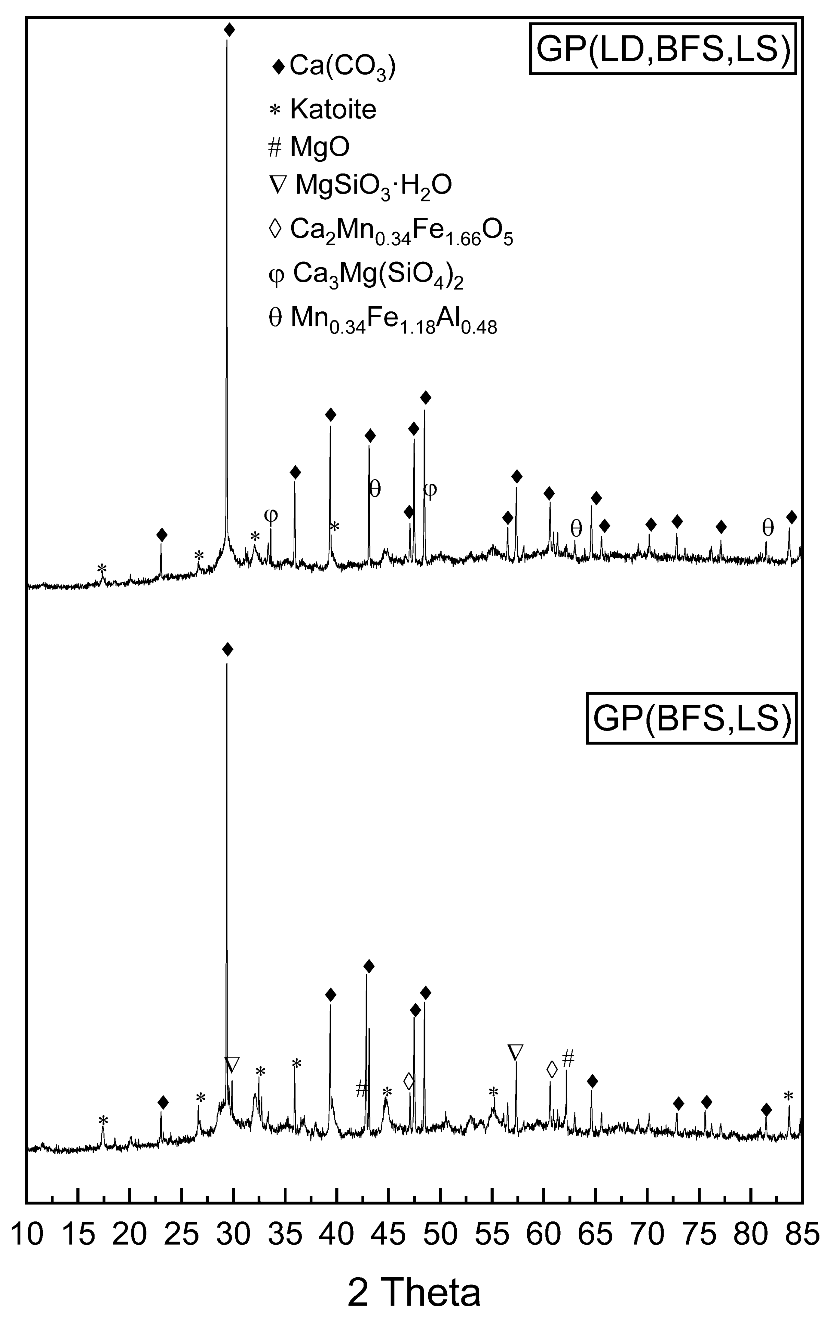
Calcium carbonate (ICDD 01-071-3699) and katoite (ICDD 01-077-0240) were identified as major peaks after geopolymerization for GP (BFS, LS) and GP (LD, BFS, LS) (Figure 2). This confirms the crystalline and amorphous phases in GP (BFS, LS) and GP (LD, BFS, LS). In the X-ray diffraction analysis, there were no peaks for silicates or aluminum silicates for these two GP samples. Further, the above peaks confirm the possible presence of aluminum and silicon, as an amorphous phase or crystalline structure was found below the detection limit.
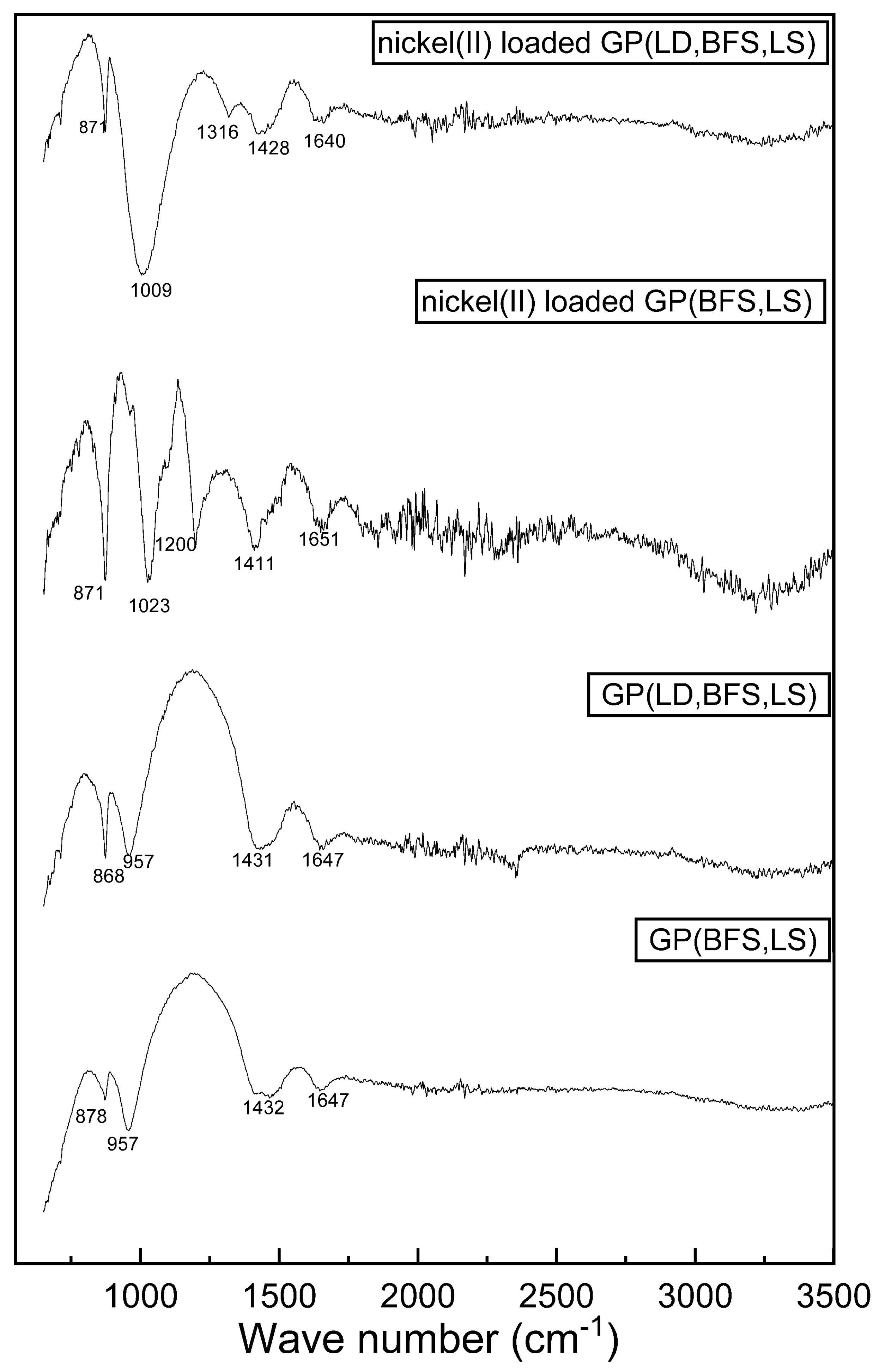
Figure 3 shows the FTIR spectra of the geopolymers and nickel(II)-loaded geopolymers that were obtained in the range 650–3500 cm−1. The peak appearing at 871–957 cm−1 corresponded to the presence of the Si–O–Si (Al) asymmetric stretch band (Luukkonen et al., 2016) [13]. This shows that a geopolymer structure exists in the produced material. The highest peak at 957 cm−1 shifted to 1009 and 1023 cm−1 in the spectra of nickel(II)-loaded GP (BFS, LS) and GP (LD, BFS, LS) that is typical in cases of metal ion adsorption [14]. At wave number 1411–1432 cm−1, the peaks can be attributed to carbon dioxide (O–C–O) that may indicate carbonate structure. The source of carbon dioxide is atmospheric [15,34]. The weak peaks at 1647–1651 cm−1 can be ascribed to the H–OH bonding in water [15], indicating that water binded to the geopolymer structure. After adsorption, two new peaks formed at 1200 and 1316 cm−1, indicating the presence of the Si–O–Al asymmetric stretch mode [35].
The slag-based geopolymers GP (BFS, LS) and GP (LD, BFS, LS) were also imagined by FESEM. Figure 4 shows that geopolymers have a crystalline surface structure due to alkaline activation occurring on the slag surface. This structure is confirmed to have sufficient pores for carrying out the adsorption methods.

3.2. Leaching Test for Stability

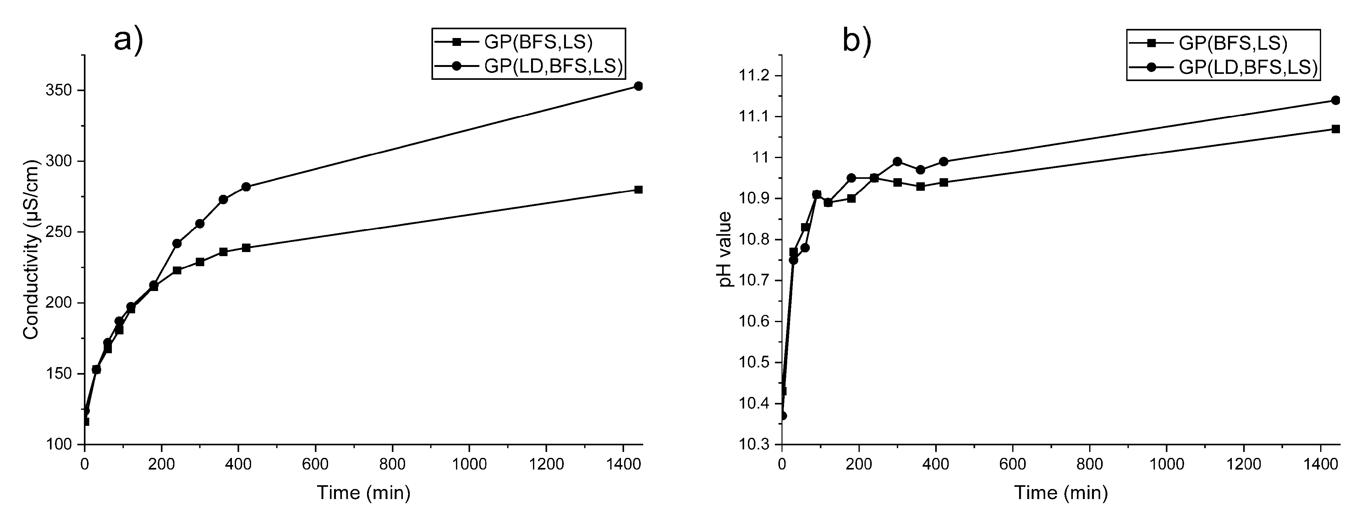
Stability tests were implemented according to Aly et al. (2008) [36] and Lancellotti et al. (2010) [37]. Washed and dried slag-based geopolymer (<0.150 mm) and distilled water in a ratio of 1:10 was placed in the Falcon tube and shaken with a laboratory shaker for 24 h. The pH value and conductivity were measured after 24 h leaching time. Geopolymers with different receipt were prepared and the stability was checked by a leaching test. A slight gradual increase in conductivity for geopolymers (GP (BFS, LS) and GP (LD, BFS, LS)) during the 24 h of leaching time indicates a slight release of ions into solution. Figure 5 shows conductance and pH values for the samples (GP (BFS, LS) and GP (LD, BFS, LS)), in which samples were taken at time intervals from 30 min to 24 h. As can be seen in Figure 5, geopolymers are alkaline materials; therefore, adsorption experiments were conducted in buffer solution to maintain the selected pH value during the experiment.

3.3. Adsorption–Regeneration Experiments

During the adsorption–regeneration experiment, the bed height, flow rate, and initial concentration were fixed at values selected from previous studies [21]. A column with 3 g of slag-based geopolymer with 0.5 cm bed height and 5 mL/min flow rate was used. Adsorption experiments were conducted by using an initial nickel(II) concentration of 50 mg/L. After adsorption, the nickel(II)-loaded geopolymers were regenerated for the next cycle. Regeneration and recycling performance are important factors for adsorbents. Moreover, reusing the adsorbent several times reduces the costs and improves the potential of commercial applications [38]. In this study, NaCl and NaOH were used as regeneration agents, and the adsorption–regeneration cycle was conducted three times. Sodium-based regeneration agents are suitable in this case because nickel ions’ removal is based on ion exchange.
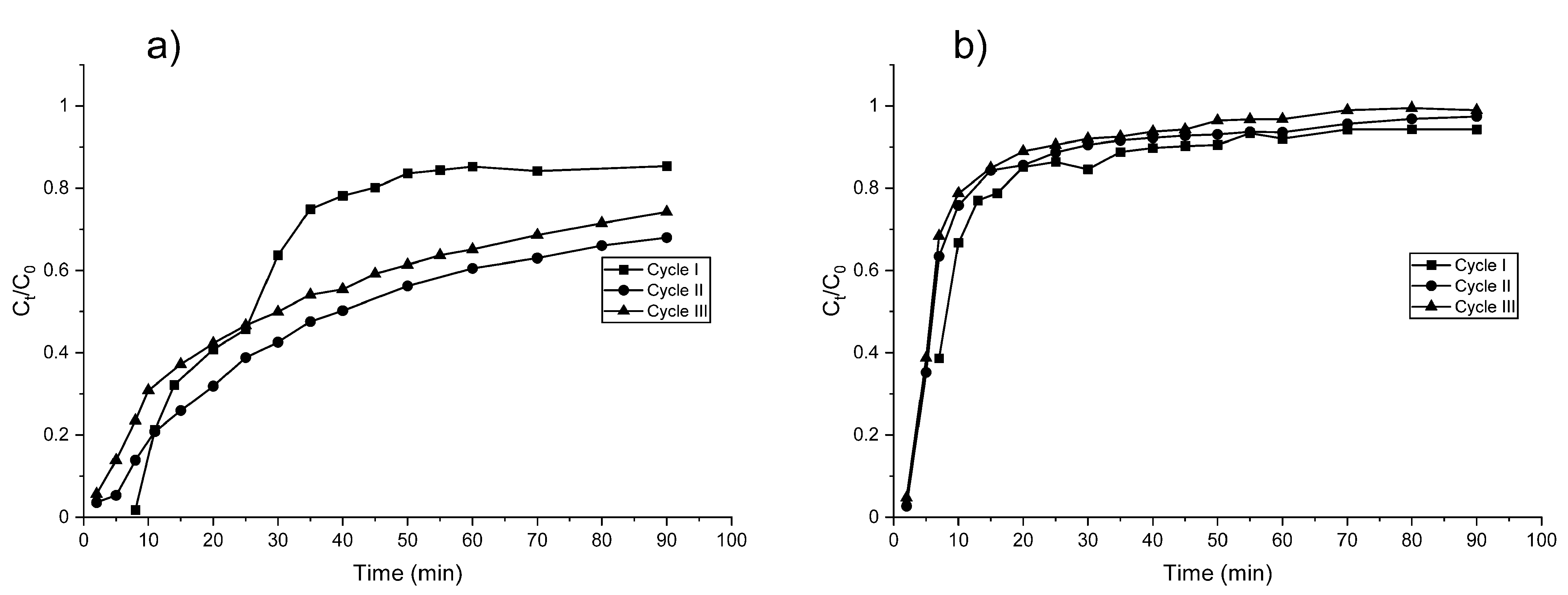
The breakthrough curve describing the effect of the nickel(II) concentration is shown in Figure 6. In the case of GP (LD, BFS, LS), the breakthrough curves became slightly steeper during the three cycles. The mass transfer zone, where the adsorption occurs, did not increase considerably during these three cycles. The adsorption efficiency of GP (LD, BFS, LS) slightly decreased during the adsorption–regeneration cycles (Table 2). The adsorption capacities were 1.34, 1.10, and 0.98 mg/g for the fresh geopolymer (cycle 1), after first regeneration (cycle 2), and after third regeneration (cycle 3), respectively. This shows the gradual decrease in the adsorption capacity when the geopolymer is reused. For GP (BFS, LS), the same trend of the breakthrough curves and the mass transfer zone occurs as for GP (LD, BFS, LS), except for cycle 1, which differed from this trend. The adsorption capacity increased during the first two cycles from 2.92 to 3.78 mg/g. The reason for this could be that the regeneration solution removed adsorbed nickel and other impurities, which caused better removal efficiency for the next adsorption cycle (cycle 2). In addition, the flow rate varied slightly (4.9–5.3 mL/min) during adsorption–regeneration cycles, which might also have some effect on the results. After cycle 2, the adsorption capacity decreased to 3.40 mg/g (cycle 3), indicating that the removal efficiency of the adsorbent started to decrease. Based on the adsorption capacities, GP (BFS, LS) was a superior adsorbent to GP (LD, BFS, LS), which is also supported by the shapes of the breakthrough curves. In the case of GP (LD, BFS, LS), the saturation was achieved after 20 min, while in the case of GP (BFS, LS), nickel adsorption still slightly continued after 90 min. The exception was cycle 1, which achieved equilibrium after 50 min.
Multiple cycles of this experiment prove the reusability and metal recovery efficiency of the adsorbent. The following results suggest that using a mixture of NaCl and NaOH solution enabled separating the nickel(II) ions by using a slag-based geopolymer. Further, the recovery efficiency of the slag-based geopolymer reduced according to the increase in the number of adsorption cycles.
In Table 3, metals’ removal with several kinds of adsorbents as a comparison to the materials studied in this paper are presented. Because ion exchange is the main adsorption mechanism, it is meaningful to compare metal cations’ removal with the same oxidation number. For example, Li and Champagne (2009) [39] reported 0.55 mg/g adsorption capacity for nickel(II) removal over mollusk shells.

3.4. Adsorption Kinetics

To demonstrate the experimental data in the initial part of the breakthrough curves, the Adams–Bohart, Thomas, and Yoon–Nelson models were used. The parameters of each model were determined from the linear plot (data not shown) of Equations (3)–(5), as shown in Table 4. Results showed that all three selected models had relatively high R2 values, ranging between 0.855 and 0.987 for GB (BFS, LS) and 0.898 and 0.993 for GP (LD, BFS, LS). The calculated q0 values in the Thomas model have a decreasing trend during the three cycles, and the values were the same order of magnitude but a little bit lower than the experimental qe values, as presented in Table 2 and Table 4. Results showed that the τ values (time for 50% breakthrough) in the Yoon–Nelson model decreased with an increasing number of cycles. This is because adsorption efficiency decreased slightly during adsorption–regeneration cycles. In the case of GP (LD, BFS, LS), τ values agreed well with the experimental data (Figure 6) in all three cycles. For GP (BFS, LS), there was slightly more difference between the τ values and the experimental data. However, all three models were quite suitable for modelling the experimental results.

4. Conclusions

To conclude this study, the nickel(II) ions were successfully removed from aqueous solution in column studies using slag-based geopolymer adsorbents GP (BFS, LS) and GP (LD, BFS, LS), which were prepared using non-conventionally used slags obtained from the steel industry. The initial nickel(II) concentration in the solution was 50 mg/L in all experiments. The nickel(II) removal capacity of each adsorbent was studied at pH 6, where nickel(II) solution was passed through the column in which a 0.5 cm bed height was used. It was observed that this provides the maximum adsorption capacity of 2.92 mg/g for GP (BFS, LS) and 1.34 mg/g for GP (LD, BFS, LS). The Adam–Bohart, Thomas, and Yoon–Nelson models fitted well to the experimental data from fixed column experiment results. Thus, the slag-based geopolymer as an adsorbent can be used in wastewater treatment to remove nickel(II) from aqueous solutions.

Author Contributions

Conceptualization, E.S.; methodology, E.S.; software, T.K., H.R. and E.S.; investigation, E.S., T.H. and T.V.; data curation, E.S., H.R., T.K. and S.T.; writing—original draft preparation, E.S.; writing—review and editing, E.S., S.T., H.R., T.K., T.H. and U.L., visualization, E.S., H.R., T.H. and T.K.; supervision, S.T., H.R. and U.L.; project administration, U.L.; funding acquisition, E.S. and U.L. All authors have read and agreed to the published version of the manuscript.

Funding

This research was funded by Maa-ja Vesitekniikan tuki ry. This work was conducted under the auspices of the Waterpro (ERDF project number: A74635, funded by the European Union, European Regional Development Fund and Leverage from the EU and Regional Councils).

Institutional Review Board Statement

Not applicable.

Informed Consent Statement

Not applicable.

Data Availability Statement

The data presented in this study are available within the article (tables and figures). The data presented in this study are available on request from the corresponding author.

Acknowledgments

The authors would like to thank Jessica Nuorala, Jaakko Pulkkinen, and Elisa Wirkkala for their help in analyzing nickel(II) ions.

Conflicts of Interest

Authors declare no conflict of interest. The funders had no role in the design of the study; in the collection, analyses, or interpretation of data; in the writing of the manuscript, or in the decision to publish the results.

References

  1. Cheng, T.; Lee, M.; Ko, M.; Ueng, T.; Yang, S. The heavy metal adsorption characteristics on metakaolin-based geopolymer. Appl. Clay Sci. 2012, 56, 90–96. [Google Scholar] [CrossRef]
  2. Siyal, A.A.; Shamsuddin, M.R.; Khan, M.I.; Rabat, N.E.; Zulfiqar, M.; Man, Z.; Siame, J.; Azizli, K.A. A review on geopolymers as emerging materials for the adsorption of heavy metals and dyes. J. Environ. Manag. 2018, 224, 327–339. [Google Scholar] [CrossRef]
  3. Ahmed, J.K.; Ahmaruzzaman, M. A review on potential usage of industrial waste materials for binding heavy metal ions from aqueous solutions. J. Water Process. Eng. 2016, 10, 39–47. [Google Scholar] [CrossRef]
  4. Al-Zboon, K.; Al-Harahsheh, M.S.; Hani, F.B. Fly ash-based geopolymer for Pb removal from aqueous solution. J. Hazard. Mater. 2011, 188, 414–421. [Google Scholar] [CrossRef] [PubMed]
  5. Javadian, H.; Ghorbani, F.; Tayebi, H.-A.; Asl, S.H. Study of the adsorption of Cd (II) from aqueous solution using zeolite-based geopolymer, synthesized from coal fly ash; kinetic, isotherm and thermodynamic studies. Arab. J. Chem. 2015, 8, 837–849. [Google Scholar] [CrossRef] [Green Version]
  6. Medpelli, D.; Sandoval, R.; Sherrill, L.; Hristovski, K.D.; Seo, D.-K. Iron oxide-modified nanoporous geopolymers for arsenic removal from ground water. Resour. Technol. 2015, 1, 19–27. [Google Scholar] [CrossRef] [Green Version]
  7. Sarkar, C.; Basu, J.K.; Samanta, A.N. Synthesis of mesoporous geopolymeric powder from LD slag as superior adsorbent for Zinc (II) removal. Adv. Powder Technol. 2018, 29, 1142–1152. [Google Scholar] [CrossRef]
  8. Al-Harahsheh, M.S.; Al Zboon, K.; Al-Makhadmeh, L.; Hararah, M.; Mahasneh, M. Fly ash based geopolymer for heavy metal removal: A case study on copper removal. J. Environ. Chem. Eng. 2015, 3, 1669–1677. [Google Scholar] [CrossRef]
  9. Duan, P.; Yan, C.; Zhou, W.; Ren, D. Development of fly ash and iron ore tailing based porous geopolymer for removal of Cu(II) from wastewater. Ceram. Int. 2016, 42, 13507–13518. [Google Scholar] [CrossRef]
  10. Ge, Y.; Yuan, Y.; Wang, K.; He, Y.; Cui, X. Preparation of geopolymer-based inorganic membrane for removing Ni2+ from wastewater. J. Hazard. Mater. 2015, 299, 711–718. [Google Scholar] [CrossRef]
  11. Luukkonen, T.; Věžníková, K.; Tolonen, E.-T.; Runtti, H.; Yliniemi, J.; Hu, T.; Kemppainen, K.; Lassi, U. Removal of ammonium from municipal wastewater with powdered and granulated metakaolin geopolymer. Environ. Technol. 2018, 39, 414–423. [Google Scholar] [CrossRef] [Green Version]
  12. Sočo, E.; Kalembkiewicz, J. Adsorption of nickel(II) and copper(II) ions from aqueous solution by coal fly ash. J. Environ. Chem. Eng. 2013, 1, 581–588. [Google Scholar] [CrossRef]
  13. Luukkonen, T.; Runtti, H.; Niskanen, M.; Tolonen, E.-T.; Sarkkinen, M.; Kemppainen, K.; Rämö, J.; Lassi, U. Simultaneous removal of Ni(II), As(III), and Sb(III) from spiked mine effluent with metakaolin and blast-furnace-slag geopolymers. J. Environ. Manag. 2016, 166, 579–588. [Google Scholar] [CrossRef]
  14. Kara, I.; Yilmazer, D.; Akar, S.T. Metakaolin based geopolymer as an effective adsorbent for adsorption of zinc(II) and nickel(II) ions from aqueous solutions. Appl. Clay Sci. 2017, 139, 54–63. [Google Scholar] [CrossRef]
  15. Sarkar, C.; Basu, J.K.; Samanta, A.N. Removal of Ni2+ ion from waste water by Geopolymeric Adsorbent derived from LD Slag. J. Water Process. Eng. 2017, 17, 237–244. [Google Scholar] [CrossRef]
  16. Goretta, K.; Chen, N.; Mora, F.G.; Routbort, J.; Lukey, G.; Van Deventer, J. Solid-particle erosion of a geopolymer containing fly ash and blast-furnace slag. Wear 2004, 256, 714–719. [Google Scholar] [CrossRef]
  17. Provis, J.L.; Van Deventer, J.S.J. Geopolymers. In Geopolymers; Elsevier: Amsterdam, The Netherlands, 2009; pp. 1–464. [Google Scholar]
  18. Ahmaruzzaman, M. A review on the utilization of fly ash. Prog. Energy Combust. Sci. 2010, 36, 327–363. [Google Scholar] [CrossRef]
  19. Lee, N.; Khalid, H.R.; Lee, H. Adsorption characteristics of cesium onto mesoporous geopolymers containing nano-crystalline zeolites. Microporous Mesoporous Mater. 2017, 242, 238–244. [Google Scholar] [CrossRef]
  20. Das, K.K.; Das, S.N.; Dhundasi, S. Nickel, its adverse health effects & oxidative stress. Indian J. Med. Res. 2008, 128, 412–425. [Google Scholar] [PubMed]
  21. Kapur, M.; Mondal, M.K. Design and model parameters estimation for fixed–bed column adsorption of Cu(II) and Ni(II) ions using magnetized saw dust. Desalination Water Treat. 2015, 57, 12192–12203. [Google Scholar] [CrossRef]
  22. Runtti, H.; Luukkonen, T.; Niskanen, M.; Tuomikoski, S.; Kangas, T.; Tynjälä, P.; Tolonen, E.-T.; Sarkkinen, M.; Kemppainen, K.; Rämö, J.; et al. Sulphate removal over barium-modified blast-furnace-slag geopolymer. J. Hazard. Mater. 2016, 317, 373–384. [Google Scholar] [CrossRef] [Green Version]
  23. Raval, N.P.; Shah, P.U.; Shah, N.K. Adsorptive removal of nickel(II) ions from aqueous environment: A review. J. Environ. Manag. 2016, 179, 1–20. [Google Scholar] [CrossRef]
  24. Jiang, D.; Yang, Y.; Huang, C.; Huang, M.; Chen, J.; Rao, T.; Ran, X. Removal of the heavy metal ion nickel (II) via an adsorption method using flower globular magnesium hydroxide. J. Hazard. Mater. 2019, 373, 131–140. [Google Scholar] [CrossRef] [PubMed]
  25. Bohart, G.S.; Adams, E.Q. Some aspects of the behavior of charcoal with respect to chlorine. J. Am. Chem. Soc. 1920, 42, 523–544. [Google Scholar] [CrossRef] [Green Version]
  26. Nguyen, L.H.; Vu, T.M.; Le, T.T.; Trinh, V.T.; Tran, T.P.; Van Tuyen, T. Ammonium removal from aqueous solutions by fixed-bed column using corncob-based modified biochar. Environ. Technol. 2019, 40, 683–692. [Google Scholar] [CrossRef]
  27. Thomas, H.C. Heterogeneous Ion Exchange in a Flowing System. J. Am. Chem. Soc. 1944, 66, 1664–1666. [Google Scholar] [CrossRef]
  28. Yoon, Y.H.; Nelson, J.H. Application of Gas Adsorption Kinetics—II. A Theoretical Model for Respirator Cartridge Service Life and Its Practical Applications. Am. Ind. Hyg. Assoc. J. 1984, 45, 517–524. [Google Scholar] [CrossRef]
  29. Djobo, J.N.; Tchadjié, L.; Tchakoute, H.; Kenne, B.; Elimbi, A.; Njopwouo, D. Synthesis of geopolymer composites from a mixture of volcanic scoria and metakaolin. J. Asian Ceram. Soc. 2014, 2, 387–398. [Google Scholar] [CrossRef] [Green Version]
  30. Huang, Y.; Han, M.; Yi, R. Microstructure and properties of fly ash-based geopolymeric material with 5A zeolite as a filler. Constr. Build. Mater. 2012, 33, 84–89. [Google Scholar] [CrossRef]
  31. Phoo-Ngernkham, T.; Chindaprasirt, P.; Sata, V.; Hanjitsuwan, S.; Hatanaka, S. The effect of adding nano-SiO2 and nano-Al2O3 on properties of high calcium fly ash geopolymer cured at ambient temperature. Mater. Des. 2014, 55, 58–65. [Google Scholar] [CrossRef]
  32. Mácová, P.; Sotiriadis, K.; Slížková, Z.; Šašek, P.; Řehoř, M.; Závada, J. Evaluation of Physical Properties of a Metakaolin-Based Alkali-Activated Binder Containing Waste Foam Glass. Materials 2020, 13, 5458. [Google Scholar] [CrossRef] [PubMed]
  33. Rasaki, S.A.; Bingxue, Z.; Guarecuco, R.; Thomas, T.; Minghui, Y. Geopolymer for use in heavy metals adsorption, and advanced oxidative processes: A critical review. J. Clean. Prod. 2019, 213, 42–58. [Google Scholar] [CrossRef]
  34. Giannopoulou, I.; Panias, D. Hydrolytic stability of sodium silicate gels in the presence of aluminum. J. Mater. Sci. 2010, 45, 5370–5377. [Google Scholar] [CrossRef]
  35. Zhang, Z.; Wang, H.; Provis, J.L. Quantitative study of the reactivity of fly ash in geopolymerization by FTIR. J. Sustain. Cem. Mater. 2012, 1, 154–166. [Google Scholar] [CrossRef] [Green Version]
  36. Aly, Z.; Vance, E.R.; Perera, D.S.; Hanna, J.V.; Griffith, C.S.; Davis, J.; Durce, D. Aqueous leachability of metakaolin-based geopolymers with molar ratios of Si/Al=1.5–4. J. Nucl. Mater. 2008, 378, 172–179. [Google Scholar] [CrossRef]
  37. Lancellotti, I.; Kamseu, E.; Michelazzi, M.; Barbieri, L.; Corradi, A.; Leonelli, C. Chemical stability of geopolymers containing municipal solid waste incinerator fly ash. Waste Manag. 2010, 30, 673–679. [Google Scholar] [CrossRef]
  38. Patel, H. Fixed-bed column adsorption study: A comprehensive review. Appl. Water Sci. 2019, 9, 45. [Google Scholar] [CrossRef] [Green Version]
  39. Li, C.; Champagne, P. Fixed-bed column study for the removal of cadmium (II) and nickel (II) ions from aqueous solutions using peat and mollusk shells. J. Hazard. Mater. 2009, 171, 872–878. [Google Scholar] [CrossRef] [PubMed]
  40. Długosz, O.; Banach, M. Sorption of Ag+ and Cu2+ by Vermiculite in a Fixed-Bed Column: Design, Process Optimization and Dynamics Investigations. Appl. Sci. 2018, 8, 2221. [Google Scholar] [CrossRef] [Green Version]
  41. Yahya, M.; Abubakar, H.; Obayomi, K.; Iyaka, Y.; Suleiman, B. Simultaneous and continuous biosorption of Cr and Cu (II) ions from industrial tannery effluent using almond shell in a fixed bed column. Results Eng. 2020, 6, 100113. [Google Scholar] [CrossRef]
  42. Borba, C.; Guirardello, R.; Silva, E.; Veit, M.; Tavares, C. Removal of nickel(II) ions from aqueous solution by biosorption in a fixed bed column: Experimental and theoretical breakthrough curves. Biochem. Eng. J. 2006, 30, 184–191. [Google Scholar] [CrossRef]
  43. Xavier, A.L.P.; Adarme, O.F.H.; Furtado, L.M.; Ferreira, G.M.D.; Da Silva, L.H.M.; Gil, L.F.; Gurgel, L.V.A. Modeling adsorption of copper(II), cobalt(II) and nickel(II) metal ions from aqueous solution onto a new carboxylated sugarcane bagasse. Part II: Optimization of monocomponent fixed-bed column adsorption. J. Colloid Interface Sci. 2018, 516, 431–445. [Google Scholar] [CrossRef] [PubMed]
  44. Rocha, A.C.D.C.; Scaratti, G.; Moura-Nickel, C.D.; Da Silva, T.L.; Vieira, M.G.A.; Peralta, R.M.; Peralta, R.A.; De Noni, A.; Moreira, R.D.F.P.M. Economical and Technological Aspects of Copper Removal from Water Using a Geopolymer and Natural Zeolite. Water Air Soil Pollut. 2020, 231, 1–15. [Google Scholar] [CrossRef]
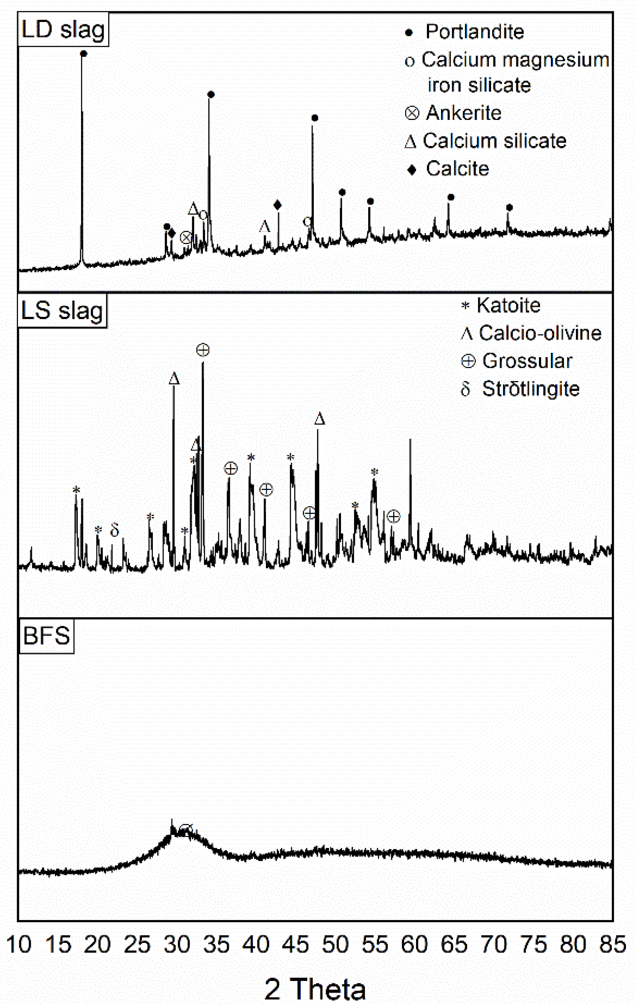
Figure 1. X-ray diffraction (XRD) pattern of raw materials LD slag, LS slag, and BFS.
Chemengineering 05 00013 g001
Figure 2. XRD patterns of geopolymers GP (BFS, LS) and GP (LD, BFS, LS).
Chemengineering 05 00013 g002
Figure 3. Fourier transform infrared (FTIR) spectra of GP (BFS, LS), GP (LD, BFS, LS), nickel(II) loaded GP (BFS, LS), and nickel(II) loaded GP (LD, BFS, LS).
Chemengineering 05 00013 g003
Figure 4. Field Emission Scanning Electron Microscope (FESEM) images of the slag-based geopolymer (a) GP (BFS, LS) and (b) GP (LD, BFS, LS).
Chemengineering 05 00013 g004
Figure 5. Conductivity value (a) and pH values (b) of GP (BFS, LS) and GP (LD, BFS, LS) as a function of time during 24 h leaching.
Chemengineering 05 00013 g005
Figure 6. Breakthrough curves for nickel(II) adsorption at 50 mg/L initial concentration and 5 mL/min flow rate: (a) GP (BFS, LS) and (b) GP (LD, BFS, LS).
Chemengineering 05 00013 g006
Table 1. X-ray fluorescence (XRF) results of raw materials blast furnace slag (BFS), ladle slag (LS), and Lintz–Donawitz converter slag (LD).
Composition (%)BFSLS SlagLD Slag
Al2O38.4227.91.5
SiO227.2011.214.6
K2O0.550.130.08
CaO38.4743.246.4
Fe-1.3813.9
FeO30.78--
TiO21.28--
Ti-0.460.47
MgO9.396.11.5
SO33.76--
S-0.250.08
Mn0.260.691.8
Na2O0.030.110.09
Table 2. Parameters of the total uptake of nickel(II) (qtotal), equilibrium nickel(II) uptake (qe), and total percentage of nickel(II) removal at a fixed-bed height and concentration during three cycles. The bed height (Z) remained almost constant during the three cycles.
AdsorbentC0
(mg/L)
Q
(mL/min)
Z
(cm)
qtotal
(mg)
qe
(mg/g)
GP (BFS, LS)
Cycle I5050.58.792.92
Cycle II5050.511.403.78
Cycle III5050.510.253.40
GP (LD, BFS, LS)
Cycle I5050.54.011.34
Cycle II5050.53.281.10
Cycle III5050.52.940.98
Table 3. Comparison of adsorption capacity of adsorbents to remove different ions in fixed-bed column. Please note that the unit for qexp is presented as in original source (mg/g, mmol/g or meq/g (milliequivalents)).
AdsorbentRemoved IonFlow Rate (mL/min)Bed Height (cm)qexpReference
VermiculiteAg+, Cu2+43Ag+: 23.96 mg/g; Cu2+: 28.39 mg/g[40]
Almond shellCr, Cu2+ (simultaneous removal)6.07.0Cr: 28.47 mg/g; Cu2+: 3.446 mg/g[41]
Marine algae, Sargassum filipendulaNi2+430.51.350 meq/g[42]
Carboxylated sugarcase bagasseCu2+1.41.661.00 mmol/g[43]
Carboxylated sugarcase bagasseCo2+1.41.830.73 mmol/g[43]
Carboxylated sugarcase bagasseNi2+1.40.980.89 mmol/g[43]
Mollusk shellsCd2+, Ni2+3.410Cd2+: 1.6 mg/g, Ni2+: 0.55 mg/g[39]
Natural zeoliteCu2+3150.15 mmol/g[44]
Geopolymer from fly ash and metakaolinCu2+3150.90 mmol/g[44]
GP (BFS, LS)Ni2+50.52.92 mg/gThis study
GP (LD, BFS, LS)Ni2+50.51.34 mg/gThis study
Table 4. Parameters of the Adams–Bohart, Thomas, and Yoon–Nelson models for nickel(II) adsorption by slag-based geopolymers GP (BFS, LS) and GP (LD, BFS, LS) cycles at a fixed-bed height, concentration, and flow rate.
Adsorbents Adams–Bohart ModelThomas ModelYoon–Nelson Model
Q
(mL/min)
kAB × 103
(L/mg min)
F
(cm/min)
N0
(mg/L)
R2kTH × 10–3
(L/min mg)
q0
(mg/g)
R2kYN
(L/min)
τ (min)R2
GP (BFS, LS)
Cycle I58.610.027147.1980.8559.7141.3220.8750.54114.7290.875
Cycle II54.890.017928.3680.9475.2931.2640.9410.24415.9200.941
Cycle III55.100.022329.1520.9785.8530.9870.9850.27412.0990.985
GP (LD, BFS, LS)
Cycle I52.250.031146.6840.8985.4600.7130.9530.2798.2750.953
Cycle II512.950.064746.5530.94716.7670.5260.9830.8396.1140.983
Cycle III510.280.065250.9160.95814.3110.5450.9930.7625.8420.993
Publisher’s Note: MDPI stays neutral with regard to jurisdictional claims in published maps and institutional affiliations.