Article

Structural, Thermodiffusive and Thermoelectric Properties of Maghemite Nanoparticles Dispersed in Ethylammonium Nitrate

1
Service de Physique de l’état Condensé, SPEC, CEA, CNRS, Université Paris-Saclay, CEA Saclay, 91191 Gif sur Yvette, CEDEX, France
2
Sorbonne Université, CNRS, Laboratoire Physicochimie des Electrolytes et Nanosystèmes Interfaciaux (PHENIX), 4 Place Jussieu, F-75005 Paris, France
3
Département de Physique—Univ. Cergy-Pontoise, 33 Bd du Port, 95011 Cergy-Pontoise, France
4
Laboratoire Léon Brillouin, CEA, CNRS, Université Paris-Saclay, CEA Saclay, 91191 Gif sur Yvette, CEDEX, France
*
Author to whom correspondence should be addressed.
These authors contributed equally to this work.
ChemEngineering 2020, 4(1), 5; https://doi.org/10.3390/chemengineering4010005
Submission received: 11 September 2019 / Revised: 27 November 2019 / Accepted: 23 December 2019 / Published: 8 January 2020

Abstract

:
Ethylammonium nitrate (ionic liquid) based ferrofluids with citrate-coated nanoparticles and Na + counterions were synthesized for a wide range of nanoparticle (NP) volume fractions ( Φ ) of up to 16%. Detailed structural analyses on these fluids were performed using magneto-optical birefringence and small angle X-ray scattering (SAXS) methods. Furthermore, the thermophoretic and thermodiffusive properties (Soret coefficient S T and diffusion coefficient D m ) were explored by forced Rayleigh scattering experiments as a function of T and Φ . They were compared to the thermoelectric potential (Seebeck coefficient, Se) properties induced in these fluids. The results were analyzed using a modified theoretical model on S T and Se adapted from an existing model developed for dispersions in more standard polar media which allows the determination of the Eastman entropy of transfer ( S ^ NP ) and the effective charge ( Z 0 e f f ) of the nanoparticles.

1. Introduction

Ferrofluids are a class of colloidal suspensions (also known as nanofluids) made of magnetic nanoparticles (NPs) dispersed in non-magnetic media. Owing to the superparamagnetic nature of individual particles and the magnetic interactions among them, ferrofluids exhibit unique and reversible properties under an external magnetic field, making them an attractive smart material for rheological (dampers [1] and sealings [2]), thermal (hyperthermic or heat transfer fluids [3]) and photonic (optical switches, all-optical magnetic sensing and controlling devices [4]) applications. Their application potential will be further extended to extreme environments, e.g., in electrospray thrusters [5] for rockets or in high-vacuum seals for microelectronic device fabrications [6], if nanoparticles (NPs) can be dispersed in carrier fluids with reduced flammability and vapor tension, and high thermal stability. Room temperature ionic liquids (RTILs) are molten salts which are liquid near room temperature and satisfy such physicochemical properties. Their high ion concentrations also lead to high electrochemical stability (see for an example, [7]) and high ionic conductivity. For these reasons, RTILs are considered a promising “green” candidate to replace more classical and dangerous organic solvents in many fields, including ferrofluids.
However, the large ion concentrations in ionic liquids renders classical theories (e.g., Poisson–Boltzmann) and experimental techniques developed for colloidal dispersions in weak electrolytes inapplicable. Consequently, the synthesis of ionic-liquid based colloidal dispersions not limited to ferrofluids, was quickly recognized as a formidable challenge to both fundamental science and engineering. Nevertheless, several examples of RTIL-based ferrofluids have been achieved, as summarized in Table 1.
Successful synthesis of such RTIL based colloidal suspensions has also paved the way for their use in electrochemical energy applications, such as batteries, fuel cells and solar cells [16]. One example of emerging electrochemical applications of ionic liquids [17], colloidal suspensions [18,19,20] and their combinations is that of thermo-electrochemical (TE) cells. In a TE-cell, two inter-dependent thermoelectric phenomena, the thermogalvanic reactions and the Seebeck effect (induced by the thermodiffusion of charged particles), convert thermal energy into electricity. (The Seebeck effect describes a thermoelectric energy conversion phenomenon occurring in the solid-state materials. The analogous process in liquids (thermogalvanic cells) was first called the “temperature coefficient” [21]. However, in recent years, the term Seebeck coefficient has been widely applied to both solids and liquid systems [22]. To be in-line with this trend, herein we also employ the term “Seebeck” to delineate the thermoelectric potential generation across two electrodes in thermogalvanic cells, due to both the oxido-reduction reactions and the internal thermoelectric field.) The thermodiffusive behaviors of colloidal particles are most often expressed in terms of the Soret coefficient S T , the proportionality coefficient between the concentration gradient and the temperature gradient in the fluid. In ionic, aqueous ferrofluids, the magnitude and the direction of S T are known to depend strongly on the ionic environment; i.e., the pH level, the counterion types and concentrations, the effective charge number of individual particles, etc. Despite such complex natures, the existing theoretical models [23,24,25,26,27] have been successfully applied to describe experimental observations [28,29,30,31] in the case of colloidal suspensions prepared in weak electrolytes. The link between the thermodiffusive motion and the resulting Seebeck potential has also been verified in ferrofluids based on weak electrolytes [18,19].
In the fledgling research involving RTIL-based ferrofluids (IL-FF), however, the thermodiffusive behaviour of colloidal particles and their impact on the thermoelectric potential generation is still unknown. Here we present a detailed investigation of a simple IL-FF system made of citrate-coated maghemite NPs, typically 7 nm in diameter, dispersed in ethylammonium nitrate (EAN) with Na + counterions (EAN-FF). To the best of our knowledge, this is the first time a systematic study of the colloidal structure of IL-FF in a wide range of volume fractions of NPs (up to 25 vol%) and their thermodiffusion properties, are reported. Furthermore, to test the pertinence of IL-FFs in thermoelectrochemical applications, we have performed the Seebeck coefficient and the power-output measurements in these EAN-FFs and compared to the colloidal nanoparticle (NP) thermodiffusion behaviour with a help of existing theoretical model.

2. Review on the Former Works Dealing with Colloidal Dispersions in EAN

Among colloidal dispersions in Ionic Liquids [8,32], dispersions of ionic maghemite nanoparticles (NPs) in ethylammonium nitrate (EAN) can be seen as a colloidal model system [33], as it is based on two components already extensively studied separately in the literature.

2.1. Ethylammonium Nitrate

EAN is a room temperature protic ionic liquid, in which a pH scale can be defined [34,35]. At room temperature, the permittivity of EAN is 26.2 and its Bjerrum length l B equals 2.1 nm. Its viscosity is known as a function of temperature [36]; it is 37.4 mPa.s at 22 C. EAN molecules form a network of hydrogen bonds, similar to that of water [37], and the small ethyl chain induces a sponge-like structure in the bulk EAN with polar and apolar domains [38]. Addition of salts in the EAN, such as lithium nitrate [39,40], zinc chloride [41] and cerium nitrate [42], shows that they are located in the polar domains and surrounded by nitrate anions.
Close to a negatively charged surface, the sponge-like structure of EAN becomes lamellar. In the first layer, the charged polar heads of EA + remain close to the negative charges on the surface and the tails associate together. Several, less organized layers are formed above the first one until the bulk sponge structure is recovered, as seen experimentally for example by AFM [43].

2.2. Maghemite Nanoparticles and Their Aqueous Dispersions

The maghemite nanoparticles were synthesized following the Massart’s method [44,45] by coprecipitation in strongly alkaline aqueous media of Fe 2 + and Fe 3 + salts. Their mean size ranges typically between 6 and 12 nm. At the end of the synthesis process, aqueous dispersions of NPs with hydroxyl surface groups are obtained at pH = 2 in nitric acid. The NPs are positively charged due to the properties of the iron oxide (pH = 7 corresponds to the point of zero charge) and this charge (typically two positive elementary charges per nm 2 ) is compensated by counterions.
An exchange of surface groups [46,47], replacing hydroxyl groups by citrate ones, leads to negatively charged NPs at pH = 7 (with two negative elementary charges per nm 2 and with a point of zero charge at pH = 2). In that case, a size sorting of the NPs [48] can be performed by taking advantage of a phase separation process to reduce the polydispersity in the size of the synthesized NPs. The colloidal stability of such dispersions has been extensively studied by small angle scattering of X-rays and of neutrons [49,50,51]. It strongly depends on the ionic strength of the dispersions [52].

2.3. Properties of the Dispersions of Maghemite NPs in EAN

NP’s dispersions in EAN were obtained by mixing an aqueous dispersion of NPs with pure EAN, and then removing the water by freeze-drying; thus, never drying the NPs alone as a powder [33]. It has been shown in [33] that the structure of the interface between the solid nanoparticle’s surface and the liquid solvent carrier is a key point for the colloidal stability of the system. In particular, Figure 1 illustrates the fact that (from a macroscopic point of view) a structural charge of the NPs in the initial aqueous system is necessary to be able to disperse the NPs in EAN, in the absence of steric interparticle repulsion with polymers. Hydroxyl coated NPs introduced in EAN from an aqueous system at their point of zero charge flocculate and they are only dispersible if the pH of the initial aqueous dispersion is low. For their part, stable dispersions of citrate coated NPs are obtained using aqueous dispersions at pH = 7, with Na + counterions. If it is mandatory that the introduced NPs have a large structural charge to be able to obtain stable dispersions in EAN, this charge can be either positive or negative.
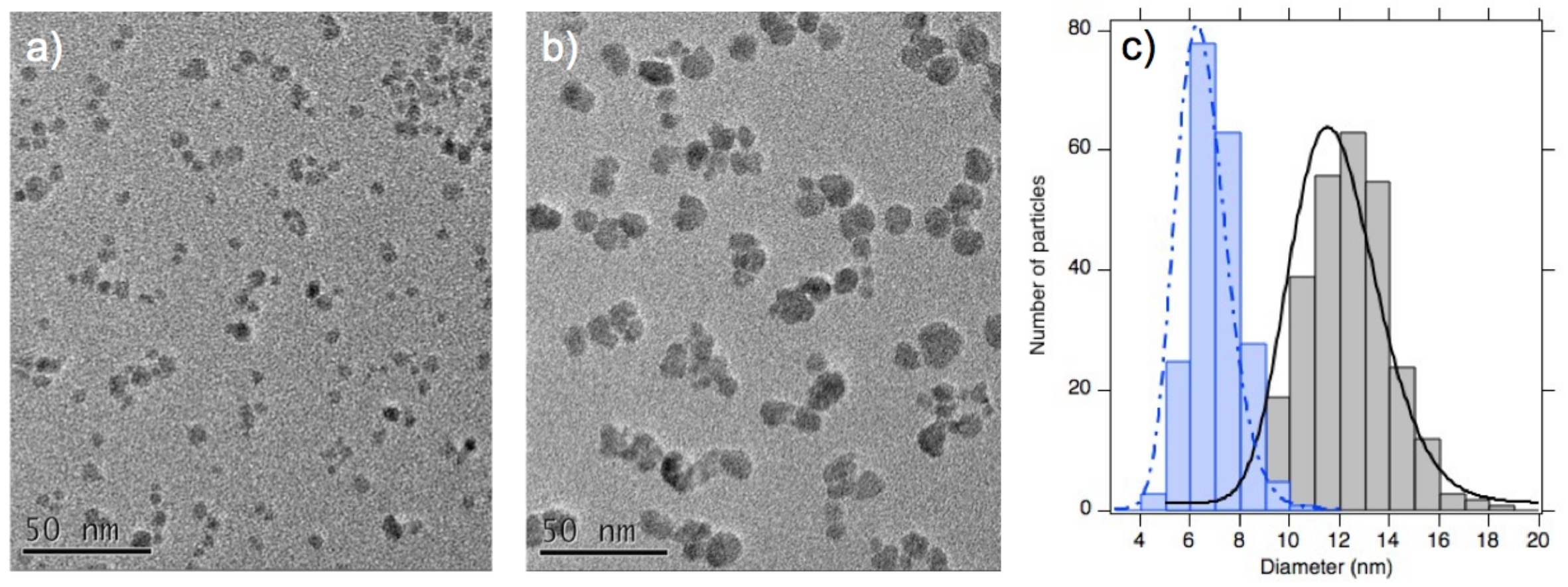
Another important point for getting concentrated monophasic dispersions in EAN is the mean size of the NPs [12,53], as it strongly influences the contribution of magnetic dipolar interaction to the total interparticle potential, modifying the dispersion microstructure. Figure 2 shows the analysis by transmission electron microscopy (TEM) of the NP’s size distribution of two samples, the one studied in [53] and hereafter in the following sections (sample A) and the one studied in [12] (sample B). Their distributions of diameters as determined by both TEM and magnetization measurements, are given in Table 2. The two techniques give very similar results, despite a small difference, expressing a narrow size distribution of these two samples. Figure 3a shows that dispersions with a typical NP diameter of 7 nm (sample A in Figure 2) present rotational diffusion properties of the NPs (as probed by magneto-optical birefringence [54,55]) which is the same at NP’s volume fractions of 0.85% and 7.67%, attesting of the good dispersion of the NPs on the nanoscale [53] in a large range of volume fractions. On the contrary, Figure 3b,c shows that a macroscopic phase separation is observed in the same conditions with a typical NP diameter of 11 nm (sample B in Figure 2). The concentrated phase issued from the demixion is even concentrated enough to present the well-known Rosensweig peak-instability of ferrofluid under a vertical magnetic field (see Figure 3c).
In [12,33] a structuration in “layers” of EAN along the solid–liquid interface of the NPs was put forward as producing an effective repulsion able to counterbalance the van der Waals and magnetic dipolar interparticle attractions. To explain the range of the interparticle potential, which leads both to colloidal stability for NP’s diameters of the order of 7 nm and to a phase separation for NP’s diameters of 11 nm, a modification of the structure of the ionic liquid over 6–7 layers around the particles before recovering its bulk sponge structure has been proposed in [12].
We thus chose, for this extensive study of the structural, thermodiffusive and thermoelectric properties of such dispersions, to use NPs from sample A (which are citrate coated and initially dispersed in water at pH = 7 with a median diameter ≈7 nm and with Na + counterions, see Figure 2) in order to deal with systems stable on the colloidal scale.

3. Preparation and Structure of the Dispersions in EAN

The dispersions of maghemite NPs in EAN were prepared with an improved method with respect to the one used in [12,33,53]. It is described below, together with the nanostructural analysis of the dispersions.

3.1. Preparation of the Samples

The initial sample in nitric acid is a colloidal dispersion in water of maghemite γ -Fe 2 O 3 NPs at a volume fraction of particles ≈1.1% (density = 5 g/cm 3 ). The same batch of initial NPs was used as in [53] (sample A). The NP’s sizes are described by the lognormal distribution of magnetic diameter given in Table 2 with a NP’s saturation magnetization m S = 302 kA/m.
The NPs’ interface is modified in water in order to be able to change the counterions of the NPs which compensate their surface charge. Citric acid is first adsorbed on the surface and is deprotonated adding a strong base; here, NaOH. The procedure described in [56] was applied, in order to have a good control of the composition of the samples. Concentration of species was indeed known thanks to this new preparation process and not measured later as in previous works. This is much easier and reproducible. The counterion used here is sodium. It is monovalent. The free tri-sodium citrate concentration in this aqueous system is 0.025 mol/L.
EAN was prepared according to [57]. EAN was then added to the aqueous dispersions, which looked stable by eye in the 50/50 EAN/water mixture. Water was then removed by freeze-drying, leading to dispersions in EAN with a volume fraction close to 1%. They looked stable from visual observation, and optical microscopy showed no heterogeneities on the micron scale. Ultracentrifugations with variable durations at 250,000×g and 25 C were then performed to obtain samples with higher volume fractions (Optima MAX-XP Ultracentrifuge from the company Beckman Coulter, USA). After 16 to 32 h of ultracentrifugation, the clear supernatant was removed and the remaining liquid was homogenized and analyzed, which produced samples between 3.5% and 25% by volume. The volume fractions can be determined by two methods. One is the material balance between the different steps: (i) before/after freeze-drying; (ii) before/after ultracentrifugation. The second is the titration of iron by ICP-MS. Both were in good agreement.

3.2. Structure from Small Angle X-ray Scattering (SAXS) at Room Temperature

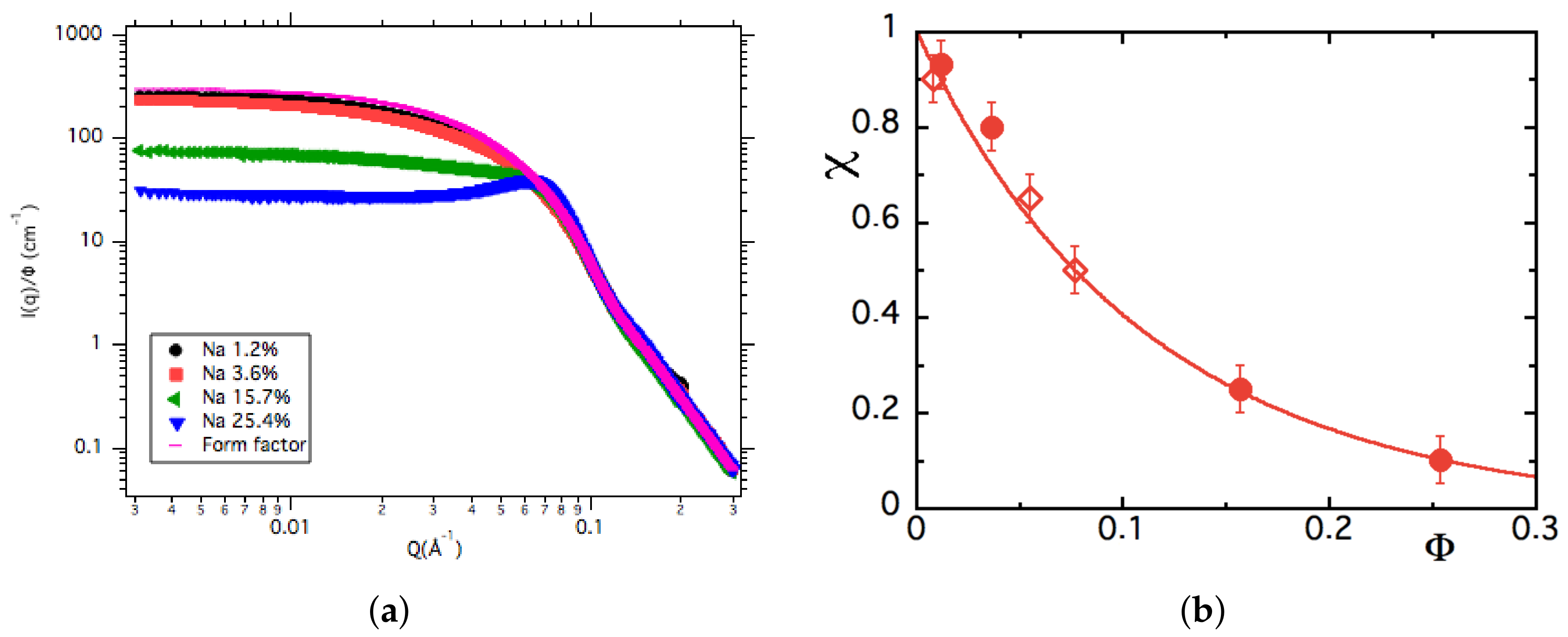
The nanostructure of the colloidal dispersions was studied by SAXS (SWING beamline of SOLEIL Synchrotron, France). The beam energy was 14,666 eV and two sample-detector distances were used to reach a range of the scattering vector Q between 3.2 × 10 3 Å 1 and 4 × 10 1 Å 1 . Figure 4a shows the evolution of the scattered intensity I ( Q ) / Φ for the available stable samples with Na + counterions. For spherical NPs, this scattered intensity can be written:
I ( Q , ϕ ) = ( Δ ρ ) 2 Φ V N P P ( Q ) S ( Q , Φ ) ,
where Δ ρ is the contrast between NPs and solvent; Φ is the NPs’ volume fraction and V N P is their volume; P(Q) is the NPs’ form factor and S(Q) their structure factor. Measurements extrapolated at zero volume fraction enable us to determine the experimental form factor, also plotted in Figure 4a, which corresponds to S(Q) = 1 in Equation (1). The comparison of I(Q 0 ) of other samples with the form factor, thus, tells us if interparticle interaction is repulsive or attractive. Figure 4a clearly shows that interaction is repulsive (I(Q 0 ) < I f o r m f a c t o r (Q 0 )).
The extrapolation of the structure factor at Q = 0 corresponds to the osmotic compressibility χ if the particles are individually dispersed. χ is related to the osmotic pressure Π by:
χ ( Φ ) = k T V NP Φ Π .
For low enough volume fractions, the virial development of the osmotic pressure at the second order links χ ( Φ ) with the second order virial coefficient A 2 by: χ = ( 1 + 2 A 2 Φ ) 1 . Here, χ < 1 and decreases with Φ (see Figure 4b); therefore, A 2 is positive and the interparticle interaction is repulsive. In this case, the compressibility χ can be analyzed up to large volume fractions (as in [30,51,56,59,60]) by the Carnahan–Starling expression for effective hard spheres [61,62]. Their volume fraction Φ eff takes into account the interparticle repulsion through a characteristic length of decrease of the interparticle repulsion, length called κ 1 (which is the analogous of the Debye screening length of interparticle electrostatic repulsion in standard polar solvents). The compressibility can be written as:
χ ( Φ ) = χ CS ( Φ eff ) = 1 Φ eff 4 1 + 4 Φ eff + 4 Φ eff 2 4 Φ eff 3 + Φ eff 4
with
Φ eff = Φ d eff 3 d NP 3 = Φ 1 + 2 κ 1 d NP 3 and d eff = d NP + 2 κ 1 .
The second virial coefficient A 2 of the osmotic pressure Π in the dispersion is, then:
A 2 = A 2 HS Φ eff Φ = 4 Φ eff Φ .
The compressibility analysis with Equations (3) and (4) using the characteristic length κ 1 as a fitting parameter and d NP = <d 3 > 1 / 3 = 7.4 nm is plotted in Figure 4b. The associated length κ 1 is small, around 0.2 nm (using the NP diameter). The corresponding range of the repulsive interparticle potential is 3–5 κ 1 (thus, 0.6 to 1 nm). The second Virial coefficient calculated with Equation (5) is A 2 = 4.6 ± 0.5 (see Table 3), a value which is very close to the hard sphere value A 2 H S = 4 . These results are comparable to previous ones obtained on the same kinds of samples with the same NP batch and with sodium counterions (see Figure 4b) [53].

3.3. Chemical Titrations of Alkaline Ions

The concentration of sodium was measured by ICP-MS (inductively coupled plasma mass spectroscopy) with a Thermo Scientific ICAP Q apparatus, in the colloidal dispersions and in the supernatants obtained by ultracentrifugation (containing no NPs). The iron concentration was checked at the same time. The volume fractions Φ of NPs determined from the iron concentration (using a density of 5 g/cm 3 for maghemite) are in good agreement with the values determined from the material balance. The titration of Na + ions enabled to determine the concentration of the free cationic counterions (not localized on the NPs) in the solvent (EAN) from the measurements in the supernatant. Comparing it to the titration of the total Na + cations in the colloidal dispersion allowed us to extract the amount of Na + linked to the nanoparticles in EAN. It could be converted to an amount of alkaline cations per surface of iron oxide. The results are summarized in Table 3.
The results first show that, in EAN, some cations are localized at the NPs’ interface, staying close to the NPs, instead of diluting randomly in the solvent. They are, thus, not all replaced by most numerous ethylammonium cations (EA + ions) in the NPs’ vicinity. This means that the amount of Na + linked to the NPs is smaller in EAN than in water, increasing the (free) concentration of Na + , not linked to NPs, compared to the initial value. However this localization exists and has already been seen in previous studies [12] with less precise values obtained formerly by atomic absorption spectroscopy. Note that, whatever the technique used, the titration of sodium remains difficult due to its ubiquitous presence.

3.4. Discussion on the Structure

The results presented above show that there is a strong influence of the NPs/IL interface on the interparticle interaction, and on the nanostructure of the dispersions. This originates from the mechanism explaining the colloidal stability in ionic liquids. It is expected to result from the organization of the ILs close to the negatively charged surface.
Let us return to the detail of our solid/liquid interface. In water, the NPs are charged thanks to the adsorbed citrate molecules. The structural charge Z s t r is known to be around two elementary charges per nm 2 [47], which corresponds here to Z s t r = 315 for one NP (–32 μ C/cm 2 ). Note that this charge is similar to the one for mica surfaces, used for many AFM studies with ILs [64], which can, thus, reasonably be compared with our results. However, NPs differ from mica due to the curvature of the interface and of their higher roughness.
Still in water, the high structural charge of the maghemite NPs induces a condensation of lots of counterions on the surface, and the static effective charge Z e f f and the dynamic one ξ o e f f determined from electrophoresis are close to 20 [30]. This effective charge and the diffuse layer around the NP are responsible for the electrostatic repulsion enabling colloidal stability in water or classical polar solvents.
While transferring the NPs to EAN, the citrate molecules stay on the surface and free citrate remains in the surrounding EAN, Na 3 Citrate salts being soluble in EAN. The structural charge to compensate at the solid/liquid interface is, thus, still two elementary charges per nm 2 . The charge compensation can be ensured by EA + cations or by Na + cations. Our results show that this compensation is at least partly due to Na + cations, which stay localized close to the NPs’ interface. Such a localization of Na + ions on a charged surface has been recently seen by AFM experiments on mica surfaces in propylammonium nitrate PAN (which has a similar structure to EAN) while adding NaNO 3 salts [64]. Concerning the structure of the interface, the important parameter appears to be the ratio Ω of the charge density of the solid surface to that of a compact monolayer of the ions of opposite charge in the first layer close to the solid surface [65]. In our case, the density should be around 40 μ C/cm 2 for EA + and larger for Na + , due to its smaller size [66]. Therefore, Ω is smaller than 1 for both cations ( Ω < 32/40 0.8 ). This means that a multilayered structure of ionic liquid is formed close to the solid surface, as shown by simulations [65]. In the same studies, they also predict an inversion of the charge in the first ionic layer at the interface, implying that the sign of the effective charge beyond the first layer is reversed, with a maximal value around 20% of the structural charge. Note that a situation with two types of cations, as in here (Na + and EA + ), has not been considered. Here, one third of the structural charge Z s t r is compensated by the sodium cations (see Table 3), and the additional compensation and overcompensation can be ensured by EA + cations.
These results give us a good static image of the solid/liquid interface with a first layer different from the following ones. Although we can estimate some orders of magnitude, the charge of the object at the top of each layer is not known. However, even knowing the apparent charge at the top of each layer, we still cannot access the effective charge ξ 0 e f f of the moving objects under applied force, as done hereafter in thermodiffusion and thermoelectric measurements. Indeed, as in water, NPs move with highly bound species around them. The effective charge ξ 0 e f f is by definition obtained at the shearing plane. However, we do not know where such plane lies in our experiments, and to the best of our knowledge, no study in the literature is capable of answering this question. We can expect that at least the first layer (above the citrate layer) close to the NPs moves with it, as it is strongly linked on the surface according to AFM studies [67], but maybe more layers move with the NP.
Within these hypotheses, one can expect a positive effective charge ξ 0 e f f with a modulus around 0.2|Z s t r |. If more than one layer moves with the NPs, the charge could be negative with a lower absolute value. That gave some limits to the following adjustments.

4. Thermodiffusive Properties

We now focus on the thermodiffusive properties of the maghemite NPs dispersed in EAN. To this end, forced Rayleigh scattering (FRS) experiments were performed. Let us begin with a short presentation on the Soret and Seebeck effect in ionic colloidal dispersions.

4.1. Theoretical Background

If a dilute dispersion of charged ionic NPs, in a polar molecular solvent, is submitted to a small gradient of temperature T , the Ludwig-Soret effect induces in the dispersion, a gradient of volume fraction Φ , which is related to T via the Soret coefficient S T :
Φ = Φ S T T .
As well, the gradient of temperature T induces in the dispersion thanks to the Seebeck effect, an internal electric field E int , which is related to T via the Seebeck coefficient S e [68] :
E int = S e T .
In the stationary conditions of the present experiment (in these conditions the flux j k of each kind of charged species k present in the solution (including the NPs) equals zero) (see Section 4.2), S T can be written (we neglect here in a first approximation the term 1 n k T Π T , which is small) according to [24,68,69,70] with the model detailed in [19,30,59] as:
S T = χ S ^ NP k T e ξ 0 e f f S e s t k T ,
χ being the osmotic compressibility of the NPs in the dispersion (see Section 3.2), S ^ NP the NP Eastman entropy of transfer, e the elementary charge and S e s t the stationary Seebeck coefficient in the conditions of the present FRS experiment.
The mass diffusion coefficient D m is related to the derivative of the osmotic pressure Π / n NP , and thus to the compressibility χ and to the friction ζ of the NPs in the colloidal dispersion through the following relations :
D m = 1 ζ Π n NP = 1 ζ k T χ and χ = k T / Π n NP
where n NP = Φ / V NP is the number of NPs per unit volume ( V NP being the NP’s volume). At low Φ s, the friction appears for hard spheres as:
ζ ζ 0 ( 1 + k F Φ HS ) with k F = 6.55
according to [71].
Hereafter we assimilate Φ HS to Φ eff and in the limit Φ = 0 , the friction expresses as :
ζ ( Φ = 0 ) = ζ 0 = 3 π η 0 d H
with η 0 the viscosity of the solvent and d H the NP’s hydrodynamic diameter.
At low Φ ’s, the diffusion coefficient can then be rewritten as
D m = k T 3 π η 0 d H χ ( 1 + k F Φ eff ) .

4.2. Forced Rayleigh Scattering Experiment

The basic principle of the forced Rayleigh scattering method used here, is described and discussed in [72,73]. (FRS implies forced inhomogeneities with respect to the spontaneous fluctuations observed in a classical Rayleigh scattering experiment [74]) The liquid dispersion is put in a thin optical cell of thickness 25 μ m and placed in a thermo-regulated sample holder, allowing work between T = 40 and 200 C. A thermal grating (of period Λ ranging between 88 and 145 μ m) is created in the dispersion thanks to the strong optical absorption of the maghemite NPs using a high power lamp (6285-500W-Hg Arc Lamp-Spectra Physics). It induces in the dispersion a concentration grating by Soret effect. Both thermal and concentration gratings were probed with the first order diffraction of a non-absorbing He-Ne laser. The Soret coefficient S T was obtained in stationary conditions thanks to the 8 Hz modulation of the Hg lamp (the thermal response of the system being by orders of magnitude faster than the concentration one-see [72,73]). The mass diffusion coefficient D m of the NPs was determined thanks to the relaxation of the concentration grating when the Hg lamp was off. The value obtained at Φ = 1.2% at room temperature is in good agreement with the results from DLS (see Table 3).

4.3. FRS Experimental Results

4.3.1. T-Dependences at Φ = 1.2 % and 3.6 %

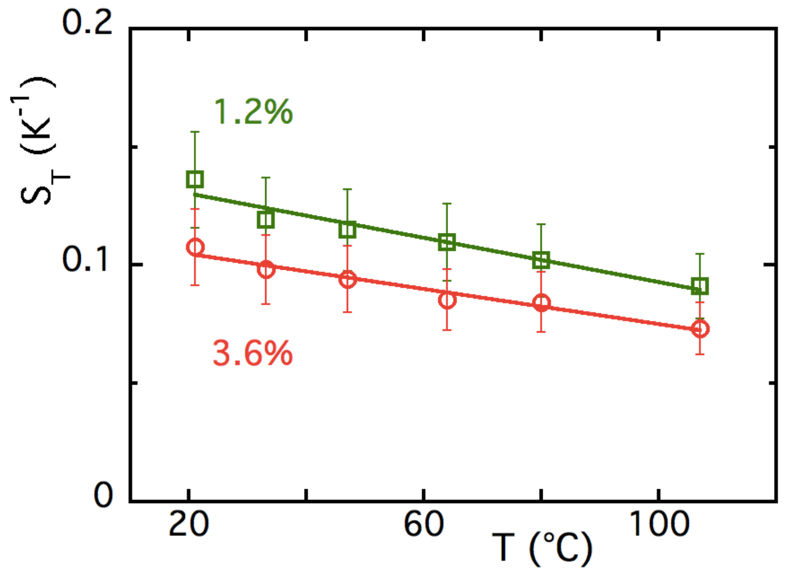
Figure 5 shows the Soret coefficient S T obtained by FRS as a function of temperature T at Φ 1.2 % and ≈3.6%. Whatever T, S T is a decreasing function of Φ . It illustrates the fact that in Equation (8) the compressibility χ of the NP system decreases if Φ increases for this repulsive NP system with A 2 > 0 . Note also that whatever Φ , S T is a decreasing function of temperature.
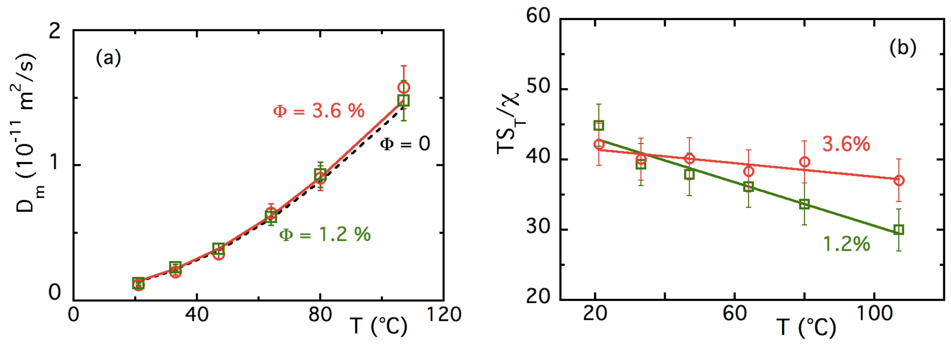
Figure 6a shows the T-evolution of the diffusion coefficient D m of the NPs at Φ 1.2 % and ≈3.6%. Within the experimental error bar, it is independent of Φ . The Φ -dependence of χ almost cancels that of 1 + k F Φ eff at room temperature, and this remains true in the whole experimental range in T and Φ of Figure 6a. The T-dependence of D m is here ruled, following Equation (12), by the viscosity η 0 of the solvent. The adjustments in Figure 6a are realized with the hypothesis χ * ( 1 + k F Φ eff ) independent of T (thus Φ e f f and χ independent of T, as k F is constant) and a NP’s hydrodynamic diameter d H 8.7 nm, compatible with the DLS results at room temperature. The quality of the fit shows that χ is indeed almost temperature-independent. This temperature-independence of χ is used in the representation of Figure 6b, where the quantity T S T / χ is plotted as a function of T for two samples at Φ = 1.2 % and 3.6 % . Using Equation (8), we obtain:
T S T χ = 1 k ( S ^ NP e ξ 0 e f f S e s t ) .
Figure 6b shows that ( S ^ NP e ξ 0 e f f S e s t ) only weakly depends on T at Φ = 3.6 % , while it decreases more steeply at Φ = 1.2 % . It is, however, difficult here to go further to separate the two contributions coming from the NP entropy of transfer S ^ N P and the Seebeck term in Equation (13); measurements at higher concentrations are necessary.

4.3.2. Φ -Dependence of S T up to ≈16% at Room Temperature

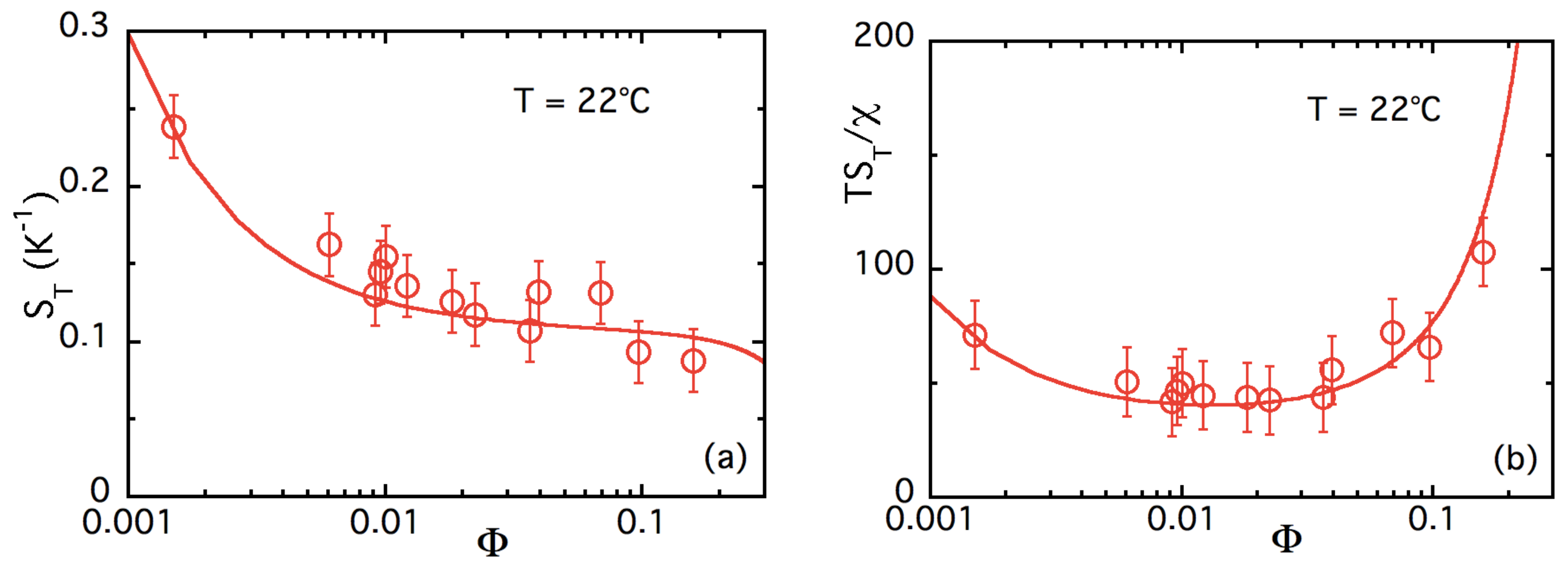
Figure 7a presents (in a semi-logarithmic representation) the experimentally observed decreasing of the room temperature Soret coefficient S T of NP’s with Φ for these samples up to Φ 16 % . To adjust the Φ -dependence of S T with Equation (8) at a given temperature, it is mandatory to express the stationary Seebeck coefficient S e s t of Equation (8) in the conditions of the FRS experiment.
Let us assume that we can use a similar model as in polar systems [19,30,59]. In a first step, we take into account the four different dissociated ionic species { i } present in the solution; namely, EA + , NO 3 , Na + and CH 3 COO (we assimilate here, as in [30,59], each rather big citrate ion to three independent monovalent CH 3 COO ions). Each of these ionic species have a charge z i = ± 1 with a number per unit volume n i .
The (static) NP’s effective charge Z 0 e f f is given by the electro-neutrality of the dispersion (see [19,30,59]) which can be written here as :
Z 0 e f f n NP + i n i z i = 0 .
This (static) NP’s effective charge Z 0 e f f is of the same order of magnitude as the (dynamic) NP’s effective charges ξ 0 e f f .
Representing that the flux of each species is null ( j N P = j i = 0 whatever { i } ) and using Equation (14), S e s t can be written as:
e S e s t = i ( n i z i S ^ i ) + n NP Z 0 e f f χ S ^ NP i ( n i z i 2 ) + n NP Z 0 e f f χ ξ 0 e f f
where S ^ i are the respective Eastman entropies of transfer of each of the dissociated species { i } in EAN. Further on, among the different dissociated ions, we disregard the ions Na + and CH 3 COO , corresponding to the NP’s initial co-and counter-ions in water. Their total concentrations (dissociated + associated; see titrations of Table 3) are very low with respect to that of EAN (dissociated + associated) ions. Further on, i = { + } corresponds to dissociated EA + ions and i = { } to dissociated NO 3 ions.
Let us first assume that the NP’s effective charge Z 0 e f f is negative (as is the NP structural charge, Z s t r ) and replace n + (which is then positive whatever the negative value of Z 0 e f f ) with Equation (14) in Equation (15). It leads to :
e S e s t ( Φ ) = S ^ + S ^ + Z 0 e f f n NP n ( χ S ^ NP S ^ + ) 2 + Z 0 e f f n NP n ( χ ξ 0 e f f 1 ) if Z 0 e f f < 0 .
Neglecting in this expression, the entropy of transfer ( S ^ + and S ^ ) of the smallest ions in front of that of the huge NPs, Equation (16) becomes:
e S e s t ( Φ ) = Z 0 e f f n NP χ S ^ NP 2 n + Z 0 e f f n NP ( χ ξ 0 e f f 1 ) if Z 0 e f f < 0
and Equation (13) can then be rewritten as:
T S T χ ( Φ ) = S ^ NP k × 2 n Z 0 e f f n NP 2 n + Z 0 e f f n NP ( χ ξ 0 e f f 1 ) if Z 0 e f f < 0 .
In this expression n N P ( Φ ) and χ ( Φ ) are known. For the sake of simplicity we assimilate here, as in [30,59,73], Z 0 e f f to ξ 0 e f f , which are considered as being Φ -independent and are, anyway, of the same order of magnitude. Three unknown parameters are, thus, remaining in Equation (18), ξ 0 e f f , S ^ N P and n (as [ N O 3 ] dis is unknown in EAN). S ^ N P has a special status as it enters as a multiplicative parameter in the expression of T S T / χ , and thus would not distort the shape of T S T / χ as a function of Φ in a log–log representation. This shape remains only function of ξ 0 e f f and n , which simplifies the adjustment. Figure 7b presents in a semi-logarithmic representation the best adjustment of T S T / χ as a function of Φ with the set of parameters of Table 4 corresponding to Z 0 e f f = ξ 0 e f f < 0.
Now, if we assume that the NP’s effective charge Z 0 e f f is positive (opposite sign with respect to the NP structural charge, Z s t r , as it is possible according to the discussion of Section 3.4), then it is n which should be replaced in Equation (15) by n + + Z 0 e f f n NP according to the electro-neutrality ( n being then positive whatever the positive value of Z 0 e f f ) leading to:
e S e s t = S ^ + S ^ + Z 0 e f f n NP n + ( χ S ^ NP S ^ ) 2 + Z 0 e f f n NP n + ( χ ξ 0 e f f + 1 ) if Z 0 e f f > 0 .
Neglecting in this expression, the entropy of transfer ( S ^ + and S ^ ) of the smallest ions in front of the huge NPs, Equation (19) becomes the analogous to Equation (17). Whatever the sign i of the NP’s effective charge Z 0 e f f , Equations (17) and (19) can be rewritten as a function of | Z 0 e f f | , leading to the general following equations :
e S e s t ( Φ ) = i | Z 0 e f f | n NP χ S ^ NP 2 n i + | Z 0 e f f | n NP ( 1 + χ | ξ 0 e f f | ) and T S T χ ( Φ ) = S ^ NP k × 2 n i + | Z 0 e f f | n NP 2 n i + | Z 0 e f f | n NP ( 1 + χ | ξ 0 e f f | ) ,
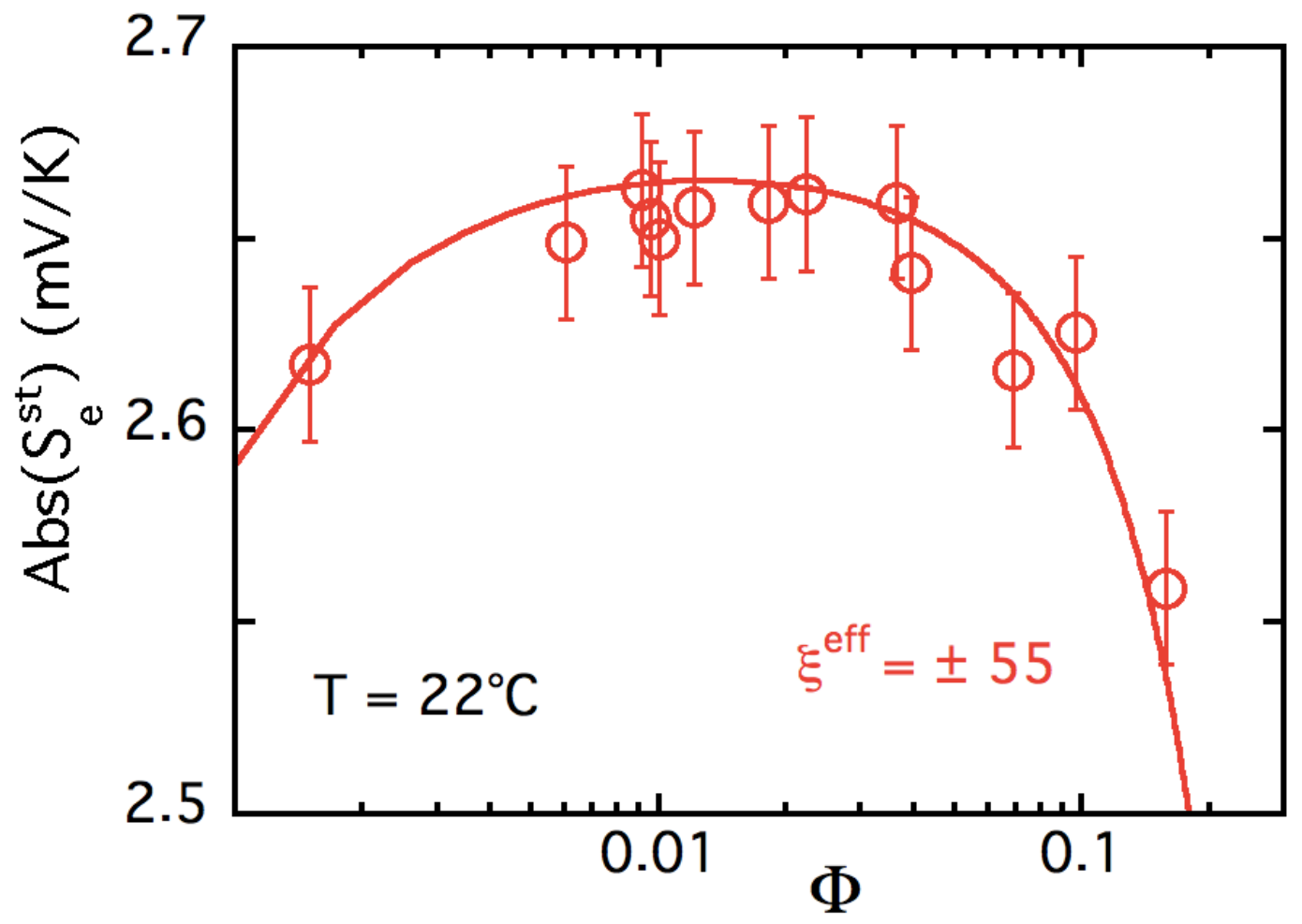
where i is the sign of Z 0 e f f . Equation (20) indeed also allows one to deduce S T ( Φ ) as χ ( Φ ) is known. The best adjustments to the experiments are summarized in Figure 7 and Figure 8, and in Table 4.
Equation (20) implies that the adjustments of S T and T S T / χ presented in Figure 7a,b (except through the meaning of index i) do not analytically depend on the sign of Z 0 e f f = ξ 0 e f f . Whatever the sign of the NP charge S ^ NP / k T is found to be positive. It equals 0.11 | Z 0 e f f | = 6.0 ± 1.6 K 1 for | Z 0 e f f | = ± 55 ± 15 (see Table 4). This absolute value is close to 20% of the structural charge mentioned above, however, its sign cannot be determined from this experiment. Then, the only thing which is modified when the sign of Z 0 e f f = ξ 0 e f f is reversed, is the meaning of the mute parameter n i in Equation (20), corresponding either to the concentration of dissociated EA + or dissociated NO 3 , these ions being of the same sign as the NP’s charge. The concentration of the dissociated complementary ions which balances the n i ’s and the NP’s charges, depends on Φ and can be easily obtained from the electro-neutrality equation (Equation (14)). It typically ranges between 0.5 × 10 3 and 6.9 × 10 3 mole/L in our Φ range. Thus, whatever the sign of the effective charge, n + and n are rather small.
Now, let us discuss on the way this effective surface charge can be structured/ built up along the NP surface in the present system only made of ions. First of all, ξ 0 e f f is the charge which is traveling with the NP when this one is moving under the action of the temperature gradient. One would expect, at the least, that the first layer of the condensed ions at the NP surface is moving with the particle. In that case, ξ 0 e f f would be positive. If ξ 0 e f f includes the second layer of condensed ions, then it will have a negative sign. In both cases the order of magnitude of | ξ 0 e f f | would be approximately the same, but it is not possible here to discriminate between the two solutions with Z 0 e f f = ξ 0 e f f = + 55 and 55 .
We can, thus, conclude that in these EAN-based ferrofluids, the NPs are stably dispersed with an interparticle repulsion almost independent of temperature, up to T = 110 C. The adjustment with a model adapted to ionic liquids of the measured Soret coefficient in a wide range of volume fractions ( 0.1 % < Φ < 16 % ), at room temperature, allows the determination of the NP’s entropy of transfer S ^ NP / k T 6.0 ± 1.6 K 1 and the absolute value of the effective NP charge | Z 0 e f f |=| ξ 0 e f f |   55 ± 15 . Those characteristics are useful for the analysis of the thermoelectric determinations of the following section.

5. Thermoelectric Properties

5.1. Production of Thermoelectric Voltage in Liquid Thermogalvanic Cells

The Equations (8) through (20) in the previous section show how the Soret coefficient ( S T ) of charged colloidal particles is closely linked to the stationary Seebeck coefficient ( S e st ) of the liquid in the FRS experiment. Furthermore, both S T and S e st depend on a set of key physical parameters of the colloidal particles; i.e., the Eastman entropy of transfer, their effective charge. However, the Seebeck coefficient described in Equations (15) and (20) is that induced by the internal electric field, which is different from the Seebeck coefficient measured with conducting electrodes used in a thermoelectro-chemical cell (hereinafter referred to as thermocell). In fact, one cannot directly measure internal electric field because the introduction of metallic electrodes creates surface effects such as the electronic double-layer formation.
To understand the different contributions to the measurable thermoelectric potential, it is helpful to understand how such a device works. The thermo-electrochemical (TE) device produces an electrical current through electrochemical reactions of dissolved reducing and oxidising species when two electrodes are maintained at different temperatures (thermogalvanic effect). In most thermocells, the total Seebeck potential Δ V = Se . Δ T (open circuit thermoelectric voltage) is primarily produced by the thermogalvanic effect, but in the case of charged colloidal suspensions, the thermodiffusion and the distribution of nanoparticles or macromolecules can modify this value.
Se = Se int Δ Δ r G e · Δ T
where Δ r G is the Gibbs free energy of the redox half reaction. Note that the chemical potential difference of electrons between the two conducting electrodes ( Δ μ e μ V/K) is considered negligible, compared to that of the solution (of the order of mV/K). The measured Seebeck coefficient between the hot and the cold electrodes is, thus, the sum of two terms with distinct origins: the internal Seebeck coefficient, Se int arises from the internal electric field, E int = Se int T , created by the ensemble of ions/particles in the solution and the term due to the redox couple. The internal electric field E int is the field experienced by one charged particle in the bulk of the solution and contributes to the Soret effect as described in Equation (8). E int can be calculated from the current J N i equation of all charged species i,
J N i = D i n i + n i S ^ i k B T T n i ξ i e k B T E int .
Combined with Equation (21), one can analytically determine two extreme states of the thermocell operation; namely, the initial state and the Soret equilibrium state. The initial state corresponds to the instance immediately after the application of a temperature gradient. At this stage, the diffusion of charged species is just starting, and thus the concentration is still uniform throughout the cell. That is, i , n i = 0 . At the Soret equilibrium, on the other hand, all particles’ fluxes stop but the concentration gradients are settled in. In between, the Seebeck voltage (and thus the Se) evolves from its initial value, Se i n i , to the steady one, Se eq . The corresponding expressions for the measurable Seebeck coefficient at the initial state, S e i n i is given by:
S e i n i = Δ V i n i Δ T = 1 e Δ s r c + i t i S ^ i ξ i
with Δ s r c being the half reaction entropy of the redox couple that can be obtained by the Nernst equation [75], and it is known to depend strongly on the ionic strength of the surrounding electrolyte [76]. The second term in Equation (23) is related to the thermodiffusion of all charged species present in the suspension with t i being the Hittorf number, which is the ratio of the conductivity σ i of the i t h species to the total conductivity σ t o t of the solution:
t i = z i ξ i e 2 n i D i i z i ξ i e 2 n i D i = σ i σ t o t .
Therefore, the initial Seebeck coefficient depends on the concentration n i of ionic species present in the solution (through their fractional conductivity), their Eastman entropy of transfer S i ^ and the effective charge number ξ i . Furthermore, depending on the relative signs of S i ^ and ξ i with respect to that of Δ S r c (Equation (23)), the thermodiffusion contribution can either enhance or reduce the S e i n i value. In a typical thermocell containing only small ions, the Eastman entropy of transfer is small for most ions, and thus the internal Seebeck coefficient is negligibly small compared to the redox reaction entropy. On the contrary, for electrolyte solutions containing large charged molecules and/or colloidal particles (e.g., ferrofluids), the second term in Equation (23) makes a measurable contribution to the total Seebeck coefficient [18,19].
It can be shown that at the other extreme condition, the Soret equilibrium, when the thermodiffusive motions of all particles are completed, the Seebeck coefficient S e s t only depends on the redox couple’s reaction entropy [27] (here, it is assumed that the Eastman entropy of transfer of redox species and that of counterions are small, and that the ionic strength at the hot and cold electrodes are not greatly modified)
S e s t = Δ s r c e .
This disappearance of internal Seebeck field is due to the rearrangement of ions (redox couple molecules and counter ions) in the solution that screens the internal electric field of the solution entirely from the electrodes [27,77]. Therefore, the thermodiffusion-induced Seebeck effect is only detectable in the initial Seebeck coefficient measurement. From Se i n i one can deduce physical parameters such as the Eastman entropy of transfer, the diffusion coefficient and the effective charge of colloidal particles via comparison to the values obtained from the thermodiffusion measurements (for a detailed derivation of the Se dependence at these two separate states, readers are kindly referred to our previous work [27]). Consequently, in the following experimental data analysis, we focus on the initial Seebeck coefficient and compare the results to the thermodiffusion behavior.

5.2. Experimental

5.2.1. Samples

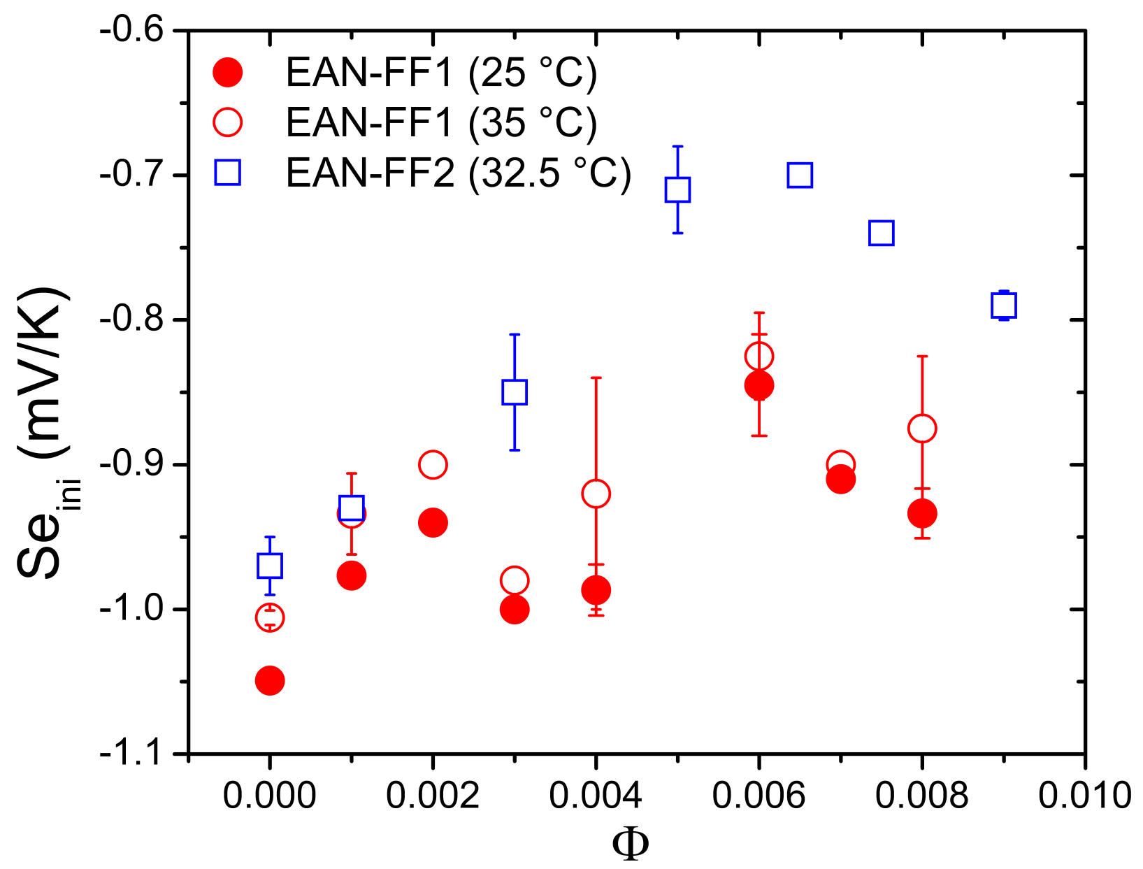
For the thermoelectric property measurements (the Seebeck coefficient and the power output generation) of EAN-FF, the redox couple (I 2 /LiI) was added (10 mM each) to the same ferrofluids at different Φ values, as described previously. For comparison, the Seebeck coefficient of a similar EAN-FF (also made with citrate-coated NPs with Na + counterions) with (I 2 /NaI) as the redox couple (3 mM each) was examined. These ferrofluids are hereafter referred to as EAN-FF1 and EAN-FF2. We emphasize that in both ferrofluids, no flocculation of nanoparticles was observed upon the redox couple inclusion. The initial Seebeck coefficient ( S e i n i ) was measured as a function of MNP concentration (0 to 0.8 volume % for FF1 and 0 to 0.9 volume % for FF2) while the redox couple concentrations were kept constant throughout the measurements.

5.2.2. Seebeck Coefficient Measurements

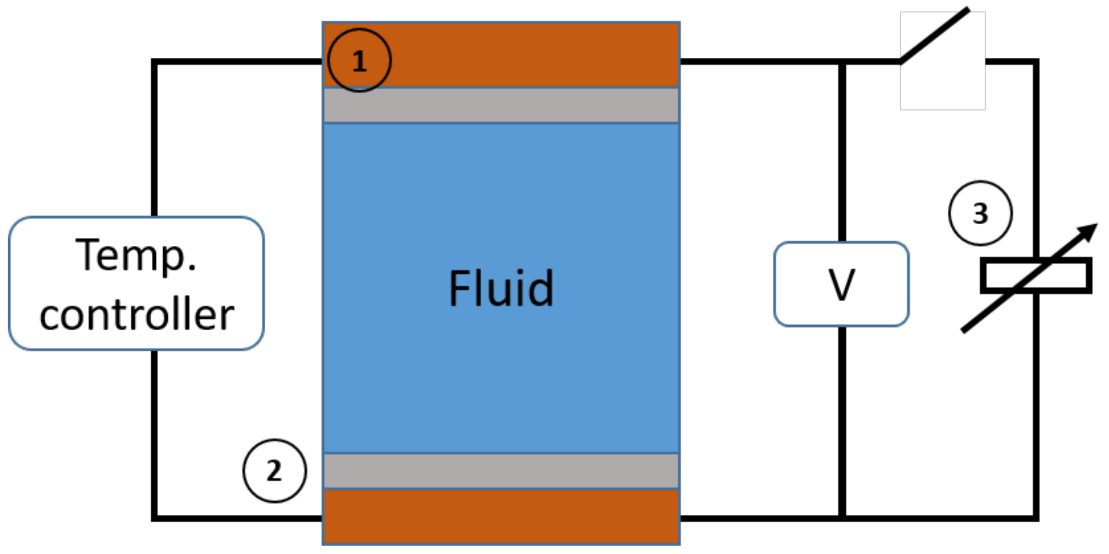
The thermoelectric voltage was measured in a single volume cylindrical cell with a central cavity [18]. The Teflon cell body, having an inner diameter of 6 mm, was sealed on both ends with two symmetrical Pt-electrodes of 10 mm diameter and 100 μ m thickness (99.99% pure, Sigma-Aldrich). Two thick Cu blocks were further screwed onto the cell body pressing the Pt electrodes against the Teflon body thereby ensuring hermetic sealing. Distance between the two electrodes was 10 mm and the surface area of the electrode in contact with the liquid was ≈0.28 cm 2 . The cell was filled through a small radial hole in the cylindrical cavity using a syringe. To avoid natural convective effects in fluid, the cell was always heated (cooled) from the top (bottom) to avoid convection. The temperature of the top and the bottom Cu blocks, which were in good thermal (and electrical) contact with the Pt electrodes, was regulated by a temperature controller (Stanford Research Systems PTC10) via Peltier modules. The application of a thermal gradient induced a thermoelectric voltage between the two electrodes, which was measured using a high impedance electrometer with a 10 14 Ω input resistance (Keithley K-6514). Both the initial and steady state Seebeck coefficients, Se i n i and Se s t , were measured as a function of nanoparticle volume fraction ( ϕ in vol.%) while applying a temperature difference of 10 K at the mean cell temperatures of 25 and 35 C for EAN-FF1. For EAN-FF2 sample, Δ T = 5 K and T m e a n = 32.5 C were used.
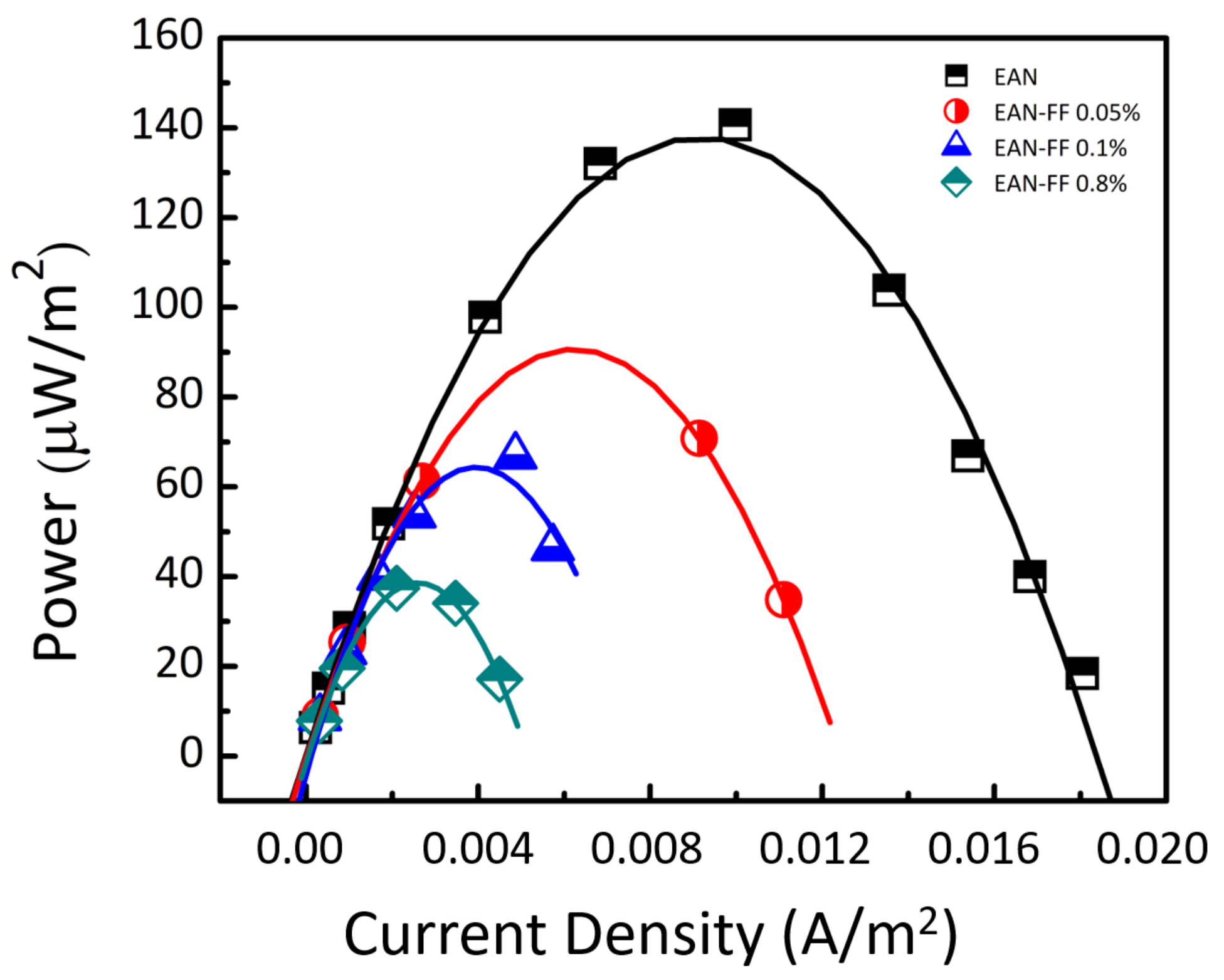
In EAN-FF1, power measurements were also carried out by connecting a variable discharge resistor ranging from 10 Ω to 10 M Ω in parallel to the thermocell (see the schematic diagram of the thermoecell measurement in Figure 9). By recording the change in thermoelectric voltage as a function of the resistance value, one can calculate the current flowing through the thermocell using Ohm’s law. For these measurements, a temperature difference of 30 K (20–50 C, T m e a n = 35 C) was imposed between the two electrodes.

5.3. Results and Discussion

In Figure 10, the initial Seebeck coefficient as a function of NP concentration of EAN-FF1 (cell mean temperature T m e a n = 25 and 35 C) and EAN-FF2 ( T m e a n = 32.5 C) samples is presented. As expected, the iodine-iodide redox couple gave a negative Seebeck coefficient [78] at Φ = 0%. (Note that this sign convention for Seebeck coefficient corresponds to that used in solid state physics. In thermogalvanic community, it is common to define Se = Δ V / Δ T ). Comparison between the three data sets also shows that the choice of cation in these iodide salt does not impact greatly the overall value of the initial Seebeck coefficient. The addition of nanoparticles reduces | Se i n i ( Φ ) | until Φ reaches about 0.6%, after which it appears to stabilize for both samples. The quantitative and qualitative similarity indicates that the observed tendency is indeed related to the presence of charged NPs and not much affected by the types of counter ions present in the redox salts.
As discussed earlier, the effect of the thermodiffusion of nanoparticles on the thermoelectric property of ferrofluids can be deduced from the initial Seebeck coefficient (Equation (23)). At a given mean cell temperature and a constant redox-couple concentrations, the variations in Se i n i ( Φ ) can be written as
e Δ Se i n i ( Φ ) = e Se i n i ( Φ ) e Se i n i ( 0 ) = 1 σ t o t ( Φ ) i σ i ( Φ ) ξ i S ^ i ( Φ ) 1 σ t o t ( 0 ) i σ i ( 0 ) ξ i S ^ i ( 0 )
where Se i n i ( 0 ) is the initial Seebeck coefficient of EAN in the absence of magnetic nanoparticles (but with the redox couple) and the thermogalvanic term, which is independent of the NP concentration, is treated as a constant and disappears from Equation (26). One would expect the total ionic conductivity, σ t o t , to be dominated by the ionic liquid itself, consisting of ≈11.2 M of EA + and NO 3 ions; i.e., σ t o t ( Φ ) σ t o t ( 0 ) . Surprisingly, the experimentally measured σ t o t ( Φ ) clearly depends on the NP concentration (see Figure 11a). More interestingly one can see from the figure that the initial Seebeck coefficient, | Se i n i ( Φ ) | follows very closely, σ t o t ( Φ ) ; i.e., initial decrease at low NP concentrations then slight increase (or nearly stable) at higher concentrations. This suggests a direct dependence between these two physical quantities, σ and S e e b e c k , as expected from Equation (23).
Assuming that the change in σ t o t ( Φ ) is due to the contributions from ionic species, whose concentration varies with Φ , and keeping only the terms that depend on the NP concentration, (the initial drop in the ionic conductivity is possibly due to the adsorption or overcrowding of NPs near the electrode-liquid interface; this point is discussed at the end of this section) the Equation (26) can be approximated to:
e Δ Se i n i ( Φ ) = 1 σ t o t ( Φ ) Δ σ d i s ( Φ ) S ^ d i s ξ d i s + σ N P ( Φ ) S ^ N P ( Φ ) ξ N P
where S ^ N P ( Φ ) = S ^ N P . χ ( Φ e f f ) , as described in the previous sections, and Δ σ d i s ( Φ ) = σ d i s ( Φ ) σ d i s ( 0 ) . Here, the subscript dis refers to the dissociated complementary ions whose concentration grows as described in Section 4.3. The dissociated complementary ion is EA + for Z 0 e f f < 0 and NO 3 for Z 0 e f f > 0. ξ d i s is ± 1 . Taking into account the electro-neutrality of the fluid, the ionic conductivity of the dissociated species and the NPs are expressed
Δ σ d i s ( Φ ) = n N P ( Φ ) | Z 0 e f f | e 2 D d i s k B T and σ N P ( Φ ) = n N P ( Φ ) ( Z 0 e f f ) 2 e 2 D m k B T
with n N P = Φ V N P . Φ e f f = 1.15 Φ according to κ 1 = 0.2 nm. One can assess the relative importance of Δ σ d i s ( Φ ) and σ N P ( Φ ) (and thus Δ t d i s and t N P ) by considering the size of the dissociated species with respect to the nanoparticles. The diffusion coefficients of EA + and NO 3 can be estimated from their molecular radii (less than 1 nm) and the viscosity of EAN through the Stokes–Einstein equation to be of the order of 5 ×10 11 m 2 s 1 , 50 times larger than that of NPs ( D m 1.3 × 10 12 m 2 s 1 (see Table 3 which depends very little on the particle concentration below ϕ = 1% at room temperature). Considering that the conductivity depends on the squared number of the effective charge, the Hittorf number Δ t d i s s is expected to be about the same order of magnitude of t N P (Note that ξ d i s s is only ±1 compared to ξ 0 e f f = Z 0 e f f ± 55 of NPs). In water, S ^ / k T of NO 3 (0.00084 K 1 ) is close to three orders of magnitude smaller than that of maghemite magnetic nanoparticles (≈0.5 K 1 ), slightly smaller than those used in this study [18,79]. Combined together, one can expect negligible contribution from the dissociated species in Δ Se i n i ( Φ ) .
Rather than guesstimating the S ^ and D m values of the dissociated species, in Figure 11b the experimentally observed evolution of Δ Se i n i ( Φ ) is compared to the theoretical model Equation (27) by keeping only the contribution from NPs (i.e., approximating that the change in the total conductivity is solely due to the NPs, and using σ ( Φ ) = 16.22 + 230.86 Φ (in mS/cm) combined with the values of S ^ N P / k T = 6 K 1 and ξ 0 e f f = Z 0 e f f = + 55 . Note here that due to the positive change in Δ Se i n i ( Φ ) detected, only a positive value of Z 0 e f f can fit the experimental data, effectively eliminating the ambiguity on the sign of Z 0 e f f encountered by the thermodiffusion data analysis. As can be seen from Figure 11b, the predicted Δ Se i n i ( Φ ) values calculated using Equation (27) (with just the NP term and using S ^ N P and Z 0 e f f values determined from the Soret coefficient measurements) coincide with the experimentally measured values. The dispersion found in the experimental data and their deviation from the theoretical curve can be attributed to the underestimation of Δ t d i s s , as discussed above. The theoretical model used here was developed initially for charged colloidal suspensions in weak electrolytes, and has been applied successfully to water and DMSO (dimethylsulfoxide)-based ferrofluids where the S T and Se coefficients were explored simultaneously. The value of the Eastman entropy of transfer found in the IL-based ferrofluid here is larger than those found in ferrofluids based on water (between −0.5 and +1.5 K 1 [18,30]) and on DMSO (≈2–3 K 1 [19,80]). The apparent compatibility found between such a model and the experimental data in both weak and strong electrolytes suggest a universal role played by the mobility ( D m ), the effective charge ( ξ 0 e f f ) and the Eastman entropy of transfer S ^ of charged colloidal particles.
Lastly, we examined the thermocell power-output as a function of NP concentration for EAN-FF1. Unlike in water-based ferrofluids [81], the power output here was found to decrease with the inclusion of magnetic nanoparticles (see Figure 12) by as much as 70%. It should be noted that the power-output is directly related to the electrical resistance of the “redox couple” species (mass transport resistance and faradic resistance) rather than the total ionic conductivity of charged species in the bulk of the solution (Figure 11a). Therefore, the observed decrease suggests that the presence of NPs interferes with the mass transport of redox couples (either via the electrostatic attraction between the redox molecules and the NPs effective charge (for Z 0 e f f > 0)) and/or via crowding (adsorption) of NPs at the electrode surface. The former would slow down the diffusive motion of redox species while the latter would limit the effective surface area accessible for redox reactions, both resulting in a reduced power output.

6. Conclusions

We have presented a systematic study on the synthesis, structure and the thermodiffusion of EAN based ferrofluids with Na + counterions. We demonstrate that the present citrate-coated NPs are stably dispersed in EAN with Na + counterions for a wide range of NP volume fraction ( Φ ). The detailed structural analysis of these NP’s dispersions revealed the interparticle repulsion and led to the determination of the second virial coefficient in these dispersions (two-body interaction term) being A 2 = 4.6 ; that is, positive, only slightly larger than that of a hard sphere system and nearly independent of temperature for 21 C < T < 110 C range. Their thermophoretic and thermodiffusive properties (Soret coefficient S T and diffusion coefficient D m ) explored by forced Rayleigh scattering experiments as a function of T and Φ , led to a diffusion coefficient D m almost independent on Φ (up to Φ 3.6 % ) and mainly ruled by the viscosity of the solvent (within the NP concentration range here explored in temperature). The Soret coefficient S T was measured at room temperature in a wider range of volume fraction ( 0.1 % < Φ < 16 % ). A modified theoretical model for S T , adapted from a previous model for dispersions in weak electrolytes, allowed, for the first time, the determination of the Eastman entropy of transfer of the NPs as S ^ NP / k T 6.0 ± 1.6 K 1 and the absolute value of the effective NP charge | Z 0 e f f | = | ξ 0 e f f | 55 ± 15 .
The inferred sign of the effective charge from the thermoelectric measurements is positive. This effective charge comes from the adsorption of EA + cations in the first ionic layer surrounding the citrate-coated NPs and moving with them, together with some Na + cations, remaining from the initial step of the synthesis, reversing the sign of the charge from the initial one in water. From the thermoelectric property investigations, both the Seebeck coefficient and the power-output were found to decrease with the NP concentration. The quantitative match between the theoretically expected values of the internal Seebeck coefficient and the experimental data demonstrates the robustness of the present model beyond weak electrolytes. Simultaneously, this also suggests that with a proper tuning of NP’s effective dynamic charge (the sign and the magnitude) and the Eastman entropy of transfer, one can hope to concoct ionic-liquid based ferrofluids where the inclusion of NPs can effectively enhance the Seebeck coefficient.

Author Contributions

Thermoelectric measurements and the corresponding data analysis were performed by K.B., T.J.S., S.N. Sample fluids were synthesized by V.P. and E.D. The structural characterizations and analysis were performed by E.D., V.P., L.M. and F.C. The thermodiffusion measurements and the corresponding data analysis were performed by M.S. G.D. and R.P. All authors contributed to writing and editing the manuscript. All authors have read and agreed to the published version of the manuscript All authors have read and agreed to the published version of the manuscript.

Funding

This research was supported by: ANR TEFLIC (grant number ANR-12-PRGE-0011-01), LabEx PALM (ANR-10-LABX-0039-PALM) and the European Union’s Horizon 2020 research and innovation programme under the grant agreement n 731976 (MAGENTA).

Acknowledgments

We thank the synchrotron SOLEIL (France) for beamtime on the SWING spectrometer and J. Perez for support during the beamtime. We deeply thank Valérie Gersteen and Elodie Barruet from LIONS, NIMBE, CEA, CNRS, Université Paris Saclay, CEA Saclay, Gif sur Yvette—France who made the ICP-MS titrations.

Conflicts of Interest

The authors declare no conflict of interest.

Abbreviations

The following abbreviations and symbols are used in this manuscript:
S T Soret coefficient
D m diffusion coefficient (of nanoparticles)
S e Seebeck coefficient
S e s t , S e i n i stationary, initial state Seebeck coefficient
S ^ , S ^ N P , S ^ ± Eastman entropy of transfer of nanoparticles, ±ions
Φ , Φ e f f nanoparticle volume fraction and effective volume fraction
n, n N P , n ± number concentration of nanoparticles and ±ions
Z, Z 0 e f f , Z s t r effective and structural charge number (of a nanoparticle)
ξ , ξ 0 e f f dynamic charge and effective dynamic charge at infinite dilution (of nanoparticles)
Δ s r c redox half reaction entropy
t, t N P , t i Hittorf number of nanoparticles and ion i
σ i , σ d i s s , σ N P conductivity of ith specie, dissociated ions and nanoparticles
χ osmotic compressibility
Π osmotic pressure
ζ friction coefficient
NPnanoparticle
RTILroom temperature ionic liquid
EANethylammonium nitrate
IL-FFionic liquid based ferrofluid
ICP-MSinductively coupled plasma mass spectroscopy
SAXSsmall angle X-ray scattering
TEthermoelectric
DLSdynamic light scattering
AFMatomic force microscopy
TEMtransmission electronc microscopy
FRSforced Rayleigh scattering

References

  1. Raj, K.; Moskowitz, R. A review of damping applications of ferrofluids. IEEE Trans. Magn. 1980, 16, 358–363. [Google Scholar] [CrossRef]
  2. Rosensweig, R. Ferrohydrodynamics; Cambridge Monographs on Mechanics and Applied Mathematics; Cambridge University Press: Cambridge, UK, 1985. [Google Scholar]
  3. Nkurikiyimfura, I.; Wang, Y.; Pan, Z. Heat transfer enhancement by magnetic nanofluids—A review. Renew. Sustain. Energy Rev. 2013, 21, 548–561. [Google Scholar] [CrossRef]
  4. Philip, J.; Kaskar, J.M. Optical Properties and Applications of Ferrofluids—A Review. J. Nanofluids 2012, 1, 3–20. [Google Scholar] [CrossRef]
  5. Gamero-Castano, M.; Hruby, V. Electrospray as a Source of Nanoparticles for Efficient Colloid Thrusters. J. Propuls. Power 2001, 17, 977–987. [Google Scholar] [CrossRef]
  6. Okabe, T.; Kondo, Y.; Yoshimoto, S.; Sasaki, S. Outgassing performance of an ionic liquid-based magnetic fluid. Vacuum 2019, 164, 30–40. [Google Scholar] [CrossRef]
  7. Bier, M.; Dietrich, S. Vapour pressure of ionic liquids. Mol. Phys. 2010, 108, 211–214. [Google Scholar] [CrossRef] [Green Version]
  8. Oliveira, F.C.C.; Rossi, L.M.; Jardim, R.F.; Rubim, J.C. Magnetic Fluids Based on γ-Fe2O3 and CoFe2O4 Nanoparticles Dispersed in Ionic Liquids. J. Phys. Chem. C 2009, 113, 8566–8572. [Google Scholar] [CrossRef]
  9. Rodriguez-Arco, L.; Lopez-Lopez, M.T.; Gonzalez-Caballero, F.; Duran, J.D.G. Steric Repulsion as a way to acheive the required stability for the preparatin of ionic liquid-based ferrofluids. J. Colloids Interfance Sci. 2011, 357, 252–254. [Google Scholar] [CrossRef]
  10. Mederios, A.; Parize, A.; Oliveira, V.; Neto, B.A.D.; Bakuzis, A.F.; Sousa, M.; Rossi, L.M.; Rubim, J.C. Magnetic Ionic Liquids Produced by the Dispersion of Magnetic Nanoparticles in 1-n-Butyl-3-methylimidazolium bis(trifluoromethanesulfonyl)imide (BMI.NTf2). Appl. Mater. Interfaces 2012, 4, 5458–5465. [Google Scholar] [CrossRef]
  11. Jain, N.; Zhang, X.; Hawkett, B.S.; Warr, G.G. Stable and Water-Tolerant Ionic Liquid Ferrofluids. Appl. Mater. Interfaces 2011, 3, 662–667. [Google Scholar] [CrossRef]
  12. Mamusa, M.; Sirieix-Plénet, J.; Cousin, F.; Perzynski, R.; Dubois, E.; Peyre, V. Concentrated assemblies of magnetic nanoparticles in Ionic Liquids. Faraday Discuss. 2015, 181, 193–209. [Google Scholar] [CrossRef] [PubMed] [Green Version]
  13. Mestrom, L. Stable ferrofluids of magnetite nanoparticles in hydrophobic ionic liquids. Nanotechnology 2015, 26, 285602. [Google Scholar] [CrossRef] [PubMed]
  14. Priyananda, P.; Sabouri, H.; Jain, N.; Hawkett, B.S. Steric Stabilization of γ-Fe2O3 Superparamagnetic Nanoparticles in a Hydrophobic Ionic Liquid and the Magnetorheological Behavior of the Ferrofluid. Langmuir 2018, 34, 3068–3075. [Google Scholar] [CrossRef] [PubMed]
  15. Shi, S.; Huang, W.; Wang, X. Ionic liquids–based magnetic nanofluids as lubricants. Lubr. Sci. 2018, 30, 73–82. [Google Scholar] [CrossRef]
  16. He, Z.; Alexandridis, P. Ionic liquid and nanoparticle hybrid systems: Emerging applications. Adv. Colloid Interface Sci. 2017, 244, 54–70. [Google Scholar] [CrossRef]
  17. Dupont, M.; MacFarlane, D.; Pringle, J. Thermo-electrochemical cells for waste heat harvesting— Progress and perspectives. Chem. Commun. 2017, 53, 6288–6302. [Google Scholar] [CrossRef]
  18. Salez, T.J.; Huang, B.T.; Rietjens, M.; Bonetti, M.; Wiertel-Gasquet, C.; Roger, M.; Filomeno, C.L.; Dubois, E.; Perzynski, R.; Nakamae, S. Can charged colloidal particles increase the thermoelectric energy conversion efficiency? Phys. Chem. Chem. Phys. 2017, 19, 9409–9416. [Google Scholar] [CrossRef] [Green Version]
  19. Huang, B.T.; Roger, M.; Bonetti, M.; Salez, T.J.; Wiertel-Gasquet, C.; Dubois, E.; Gomes, R.C.; Demouchy, G.; Mériguet, G.; Peyre, V.; et al. Thermo-electric diffusion of magnetic nanoparticles: Alternative path toward future thermocell applications. J. Chem. Phys. 2015, 143, 054902. [Google Scholar] [CrossRef]
  20. Alzahrani, H.; Buckingham, M.A.; Marken, M.; Aldous, L. Success and failure in the incorporation of gold nanoparticles inside ferri/ferrocyanide thermogalvanic cells. Electrochem. Commun. 2019, 102, 41–45. [Google Scholar] [CrossRef]
  21. deBethune, A.J.; Licht, T.S.; Swendeman, N. The Temperature Coefficients of Electrode Potentials—The Isothermal and Thermal Coefficients—The Standard Ionic Entropy of Electrochemical Transport of the Hydrogen Ion. J. Electrochem. Soc. 1959, 106, 616–625. [Google Scholar] [CrossRef]
  22. Quickenden, T.I.; Mua, Y. A Review of Power Generation in Aqueous Thermogalvanic Cells. J. Electrochem. Soc. 1995, 142, 3985–3994. [Google Scholar] [CrossRef]
  23. Würger, A. Thermal non-equilibrium transport in colloids. Rep. Prog. Phys. 2010, 73, 126601. [Google Scholar] [CrossRef]
  24. Burelbach, J.; Frenkel, D.; Pagonabarraga, I.; Eiser, E. A unified description of colloidal thermophoresis. Eur. Phys. J. E 2017, 41, 7. [Google Scholar] [CrossRef] [PubMed] [Green Version]
  25. Di Lecce, S.; Bresme, F. Thermal Polarization of Water Influences the Thermoelectric Response of Aqueous Solutions. J. Phys. Chem. B 2018, 122, 1662–1668. [Google Scholar] [CrossRef] [PubMed] [Green Version]
  26. Stout, R.F.; Khair, A.S. Diffuse charge dynamics in ionic thermoelectrochemical systems. Phys. Rev. E 2017, 96, 022604. [Google Scholar] [CrossRef] [Green Version]
  27. Salez, T.J.; Nakamae, S.; Perzynski, R.; Mériguet, G.; Cēbers, A.; Roger, M. Thermoelectricity and Thermodiffusion in Magnetic Nanofluids: Entropic Analysis. Entropy 2018, 20, 405. [Google Scholar] [CrossRef] [Green Version]
  28. Putnam, S.A.; Cahill, D.G. Transport of nanoscale latex spheres in a temperature gradient. Langmuir 2005, 21, 5317–5323. [Google Scholar] [CrossRef] [PubMed]
  29. Eslahian, K.A.; Maskos, M. Hofmeister effect in thermal field- flow fractionation of colloidal aqueous dispersions. Colloids Surf. A 2012, 413, 65–70. [Google Scholar] [CrossRef]
  30. Kouyaté, M.; Filomeno, C.; Demouchy, G.; Mériguet, G.; Nakamae, S.; Peyre, V.; Roger, M.; Cebers, A.; Depeyrot, J.; Dubois, E.; et al. Thermodiffusion of citrate-coated γ-Fe2O3 nanoparticles in aqueous dispersions with tuned counter-ions—Anisotropy of the Soret coefficient under magnetic field. Phys. Chem. Chem. Phys. 2019, 21, 1895–1903. [Google Scholar] [CrossRef]
  31. Braun, D.; Libchaber, A. Thermal force approach to molecular evolution. Phys. Biol. 2004, 1, 1–8. [Google Scholar] [CrossRef]
  32. Ueno, K.; Inaba, A.; Kondoh, M.; Watanabe, M. Colloidal Stability of Bare and Polymer-Grafted Silica Nanoparticles in Ionic Liquids. Langmuir 2008, 24, 5253–5259. [Google Scholar] [CrossRef]
  33. Mamusa, M.; Siriex-Plénet, J.; Cousin, F.; Dubois, E.; Peyre, V. Tuning the colloidal stability in ionic liquids by controlling the nanoparticles/liquid interface. Soft Matter 2013, 10, 1097–1101. [Google Scholar] [CrossRef] [Green Version]
  34. Benlhima, N.; Lemordant, D.; Letellier, P. Propriétés physicochimiques des mélanges eau-nitrate d’éthylammonium fondu, à 298 K. Échelles d’acidité—Solubilités. J. Chim. Phys. Phys. Chim. Biol. 1989, 86, 1919–1939. [Google Scholar] [CrossRef]
  35. Kanzaki, R.; Uchida, K.; Hara, S.; Umebayashi, Y.; Ishiguro, S.I.; Nomura, S. Acid–Base Property of Ethylammonium Nitrate Ionic Liquid Directly Obtained Using Ion-selective Field Effect Transistor Electrode. Chem. Lett. 2007, 36, 684–685. [Google Scholar] [CrossRef]
  36. Smith, J.A.; Webber, G.B.; Warr, G.G.; Atkin, R. Rheology of Protic Ionic Liquids and Their Mixtures. J. Phys. Chem. B 2013, 117, 13930–13935. [Google Scholar] [CrossRef] [PubMed]
  37. Fumino, K.; Wulf, A.; Ludwig, R. Hydrogen Bonding in Protic Ionic Liquids: Reminiscent of Water. Angew. Chem. Int. Ed. 2009, 48, 3184–3186. [Google Scholar] [CrossRef]
  38. Hayes, R.; Imberti, S.; Warr, G.G.; Atkin, R. Amphiphilicity determines nanostructure in protic ionic liquids. Phys. Chem. Chem. Phys. 2011, 13, 3237–3247. [Google Scholar] [CrossRef]
  39. Hayes, R.; Bernard, S.A.; Imberti, S.; Warr, G.G.; Atkin, R. Solvation of Inorganic Nitrate Salts in Protic Ionic Liquids. J. Phys. Chem. C 2014, 118, 21215–21225. [Google Scholar] [CrossRef]
  40. Méndez-Morales, T.; Carrete, J.; Cabeza, O.; Russina, O.; Triolo, A.; Gallego, L.J.; Varela, L.M. Solvation of Lithium Salts in Protic Ionic Liquids: A Molecular Dynamics Study. J. Phys. Chem. B 2014, 118, 761–770. [Google Scholar] [CrossRef]
  41. D’Angelo, P.; Zitolo, A.; Ceccacci, F.; Caminiti, R.; Aquilanti, G. Structural characterization of zinc(II) chloride in aqueous solution and in the protic ionic liquid ethyl ammonium nitrate by X-ray absorption spectroscopy. J. Chem. Phys. 2011, 135, 154509. [Google Scholar] [CrossRef]
  42. Serva, A.; Migliorati, V.; Spezia, R.; D’Angelo, P. How Does Ce III Nitrate Dissolve in a Protic Ionic Liquid? A Combined Molecular Dynamics and EXAFS Study. Chem. Eur. J. 2017, 23, 8424–8433. [Google Scholar] [CrossRef] [PubMed]
  43. Hayes, R.; Warr, G.G.; Atkin, R. At the interface: Solvation and designing ionic liquids. Phys. Chem. Chem. Phys. 2010, 12, 1709–1723. [Google Scholar] [CrossRef] [PubMed]
  44. Massart, R. Préparation de ferrofluides aqueux en l’absence de surfactant; comportement en fonction du pH et de la nature des ions présents en solution. C. R. Acad. Sci. Paris Série C 1980, 291, 1–3. [Google Scholar]
  45. Massart, R. Preparation of aqueous magnetic liquids in alkaline and acidic media. IEEE Trans. Mag. Magn. 1981, 17, 1247–1248. [Google Scholar] [CrossRef]
  46. Bacri, J.C.; Perzynski, R.; Salin, D.; Cabuil, V.; Massart, R. Ionic ferrofluids/ A crossing of chemistry and physics. J. Magn. Magn. Mater. 1990, 85, 27–32. [Google Scholar] [CrossRef]
  47. Dubois, E.; Cabuil, V.; Boué, F.; Perzynski, R. Structural analogy between aqueous and oily magnetic fluids. J. Chem. Phys. 1999, 111, 7147–7160. [Google Scholar] [CrossRef]
  48. Massart, R.; Dubois, E.; Cabuil, V.; Hasmonay, E. Preparation and properties of monodispersed magnetic fluids. J. Magn. Magn. Mat. 1995, 149, 1–5. [Google Scholar] [CrossRef]
  49. Dubois, E.; Perzynski, R.; Boué, F.; Cabuil, V. Liquid-Gas transitions in charged colloidal dispersions: Small Angle Neutron Scattering coupled with phase diagrams of magnetic fluids. Langmuir 2000, 16, 5617–5625. [Google Scholar] [CrossRef]
  50. Mériguet, G.; Cousin, F.; Dubois, E.; Boué, F.; Cēbers, A.; Farago, B.; Perzynski, R. What tunes the structural anisotropy of magnetic fluids under a magnetic field? J. Phys. Chem. B 2006, 110, 4378–4386. [Google Scholar] [CrossRef]
  51. Wandersman, E.; Cēbers, A.; Dubois, E.; Mériguet, G.; Robert, A.; Perzynski, R. The cage elasticity and under-field structure of concentrated magnetic colloids probed by small-angle X-ray scattering. Soft Matter 2013, 9, 11480–11489. [Google Scholar] [CrossRef] [Green Version]
  52. Cousin, F.; Dubois, E.; Cabuil, V. Tuning the interactions of a magnetic colloidal suspension. Phys. Rev. E 2003, 68, 021405. [Google Scholar] [CrossRef] [PubMed]
  53. Mamusa, M.; Sirieix-Plénet, J.; Cousin, F.; Perzynski, R.; Dubois, E.; Peyre, V. Microstructure of colloidal dispersions in the ionic liquid ethylammonium nitrate: Influence of the nature of the nanoparticles’ counterion. J. Phys. Condens. Matter 2014, 26, 284113. [Google Scholar] [CrossRef]
  54. Bacri, J.C.; Dumas, J.; Gorse, D.; Perzynski, R.; Salin, D. Ferrofluid viscometer. J. Phys. Lett. 1985, 46, L1199–L1205. [Google Scholar] [CrossRef] [Green Version]
  55. Wandersman, E.; Dupuis, V.; Dubois, E.; Perzynski, R. Rotational dynamics and aging in a magnetic colloidal glass. Phys. Rev. E 2009, 80, 041504. [Google Scholar] [CrossRef] [PubMed]
  56. Filomeno, C.L.; Kouyaté, M.; Peyre, V.; Demouchy, G.; Campos, A.F.C.; Perzynski, R.; Tourinho, F.A.; Dubois, E. Tuning the Solid/Liquid Interface in Ionic Colloidal Dispersions: Influence on Their Structure and Thermodiffusive Properties. J. Phys. Chem. C 2017, 121, 5539–5550. [Google Scholar] [CrossRef]
  57. Evans, D.; Yamauchi, A.; Roman, R.; Casassa, E. Micelle formation in ethylammonium nitrate, a low-melting fused salt. J. Colloid Interface Sci. 1982, 88, 89–96. [Google Scholar] [CrossRef]
  58. Mamusa, M. Colloidal Interactions in Ionic Liquids. Ph.D. Thesis, Universitée Pierre et Marie Curie, Paris, France, 2014. [Google Scholar]
  59. Cabreira-Gomes, R.; da Silva, A.F.; Kouyaté, M.; Demouchy, G.; Mériguet, G.; Aquino, R.; Dubois, E.; Nakamae, S.; Roger, M.; Depeyrot, J.; et al. Thermodiffusion of repulsive charged nanoparticles—The interplay between single-particle and thermoelectric contributions. Phys. Chem. Chem. Phys. 2018, 20, 16402–16413. [Google Scholar] [CrossRef]
  60. Filomeno, C.L.; Kouyaté, M.; Cousin, F.; Demouchy, G.; Dubois, E.; Michot, L.; Mériguet, G.; Perzynski, R.; Peyre, V.; Sirieix-Plénet, J.; et al. Ionic magnetic fluids in polar solvents with tuned counter-ions. J. Magn. Magn. Mat. 2017, 431, 2–7. [Google Scholar] [CrossRef] [Green Version]
  61. Carnahan, N.F.; Starling, K.E. Thermodynamic Properties of a Rigid-Sphere Fluid. J. Chem. Phys. 1970, 53, 600. [Google Scholar] [CrossRef]
  62. Barker, J.A.; Henderson, D. Perturbation Theory and Equation of State for Fluids. II. A Successful Theory of Liquids. J. Chem. Phys. 1967, 47, 4714–4721. [Google Scholar] [CrossRef]
  63. Mähler, J.; Persson, I. A Study of the Hydration of the Alkali Metal Ions in Aqueous Solution. Inorg. Chem. 2012, 51, 425–438. [Google Scholar] [CrossRef] [PubMed]
  64. McDonald, S.; Elbourne, A.; Warr, G.G.; Atkin, R. Metal ion adsorption at the ionic liquid–mica interface. Nanoscale 2016, 8, 906–914. [Google Scholar] [CrossRef] [PubMed]
  65. Ivaništšev, V.; O’Connor, S.; Fedorov, M. Poly(a)morphic portrait of the electrical double layer in ionic liquids. Electrochem. Commun. 2014, 48, 61–64. [Google Scholar] [CrossRef] [Green Version]
  66. Ivanistsev, V.; Fedorov, M.V. Interfaces between Charged Surfaces and Ionic Liquids: Insights from Molecular Simulations. Interface Mag. 2014, 23, 65–69. [Google Scholar] [CrossRef] [Green Version]
  67. Segura, J.J.; Elbourne, A.; Wanless, E.J.; Warr, G.G.; Voïtchovsky, K.; Atkin, R. Adsorbed and near surface structure of ionic liquids at a solid interface. Phys. Chem. Chem. Phys. 2013, 15, 3320. [Google Scholar] [CrossRef] [Green Version]
  68. Majee, A.; Würger, A. Collective thermoelectrophoresis of charged colloids. Phys. Rev. E 2011, 83, 061403. [Google Scholar] [CrossRef] [Green Version]
  69. Würger, A. Transport in Charged Colloids Driven by Thermoelectricity. Phys. Rev. Lett. 2008, 101, 108302. [Google Scholar] [CrossRef] [PubMed] [Green Version]
  70. Piazza, R.; Parola, A. Thermophoresis in colloidal suspensions. J. Phys. Condens. Matter 2008, 20, 153102. [Google Scholar] [CrossRef]
  71. Batchelor, G.K. Sedimentation in a dilute polydisperse system of interacting spheres. Part 1. General theory. J. Fluid Mech. 1982, 119, 379–408. [Google Scholar] [CrossRef] [Green Version]
  72. Demouchy, G.; Mezulis, A.; Bée, A.; Talbot, D.; Bacri, J.C.; Bourdon, A. Diffusion and thermodiffusion studies in ferrofluids with a new two-dimensional forced Rayleigh-scattering technique. J. Phys. D Appl. Phys. 2004, 37, 1417–1428. [Google Scholar] [CrossRef]
  73. Sarkar, M.; Riedl, J.; Demouchy, G.; Gélébart, F.; Mériguet, G.; Peyre, V.; Dubois, E.; Perzynski, R. Inversion of thermodiffusive properties of ionic colloidal dispersions in water-DMSO mixtures probed by forced Rayleigh scattering. Eur. Phys. J. E 2019, 42, 2979–2989. [Google Scholar] [CrossRef]
  74. Nagasaka, Y.; Hatakeyama, T.; Osuka, M.; Nagashima, A. Measurement of the thermal diffusivity of liquids by the forced Rayleigh scattering method: Theory and experiment. Rev. Sci. Instrum. 1988, 59, 1156. [Google Scholar] [CrossRef]
  75. Nernst, W. Die elektromotorische wirksamkeit der jonen. Z. Für Phys. Chem. 1889, 4, 129–181. [Google Scholar]
  76. Debye, P.; Hückel, E. Zur Theorie der Elektrolyte. I. Gefrierpunktserniedrigung und verwandte Erscheinungen. Phys. Z. 1923, 24, 185–206. [Google Scholar]
  77. Agar, J.N.; Turner, J.C.R. Thermal Diffusion in Solutions of Electrolytes. Proc. R. Soc. Lond. A Math. Phys. Eng. Sci. 1960, 255, 307–330. [Google Scholar]
  78. Laux, E.; Jeandupeux, L.; Uhl, S.; Keppner, H.; Pérez López, P.; Sanglard, P.; Vanoli, E.; Marti, R. Novel Ionic Liquids for Thermoelectric Generator Devices. Mater. Today Proc. 2019, 8, 672–679. [Google Scholar] [CrossRef]
  79. Agar, J.N.; Mou, C.Y.; Lin, J.L. Single-ion heat of transport in electrolyte solutions: A hydrodynamic theory. J. Phys. Chem. 1989, 93, 2079–2082. [Google Scholar] [CrossRef]
  80. Salez, T.J.; Kouyaté, M.; Filomeno, C.; Bonetti, M.; Roger, M.; Demouchy, G.; Dubois, E.; Perzynski, R.; Cebers, A.; Nakamae, S. Magnetically enhancing the Seebeck coefficient in ferrofluids. Nanoscale Adv. 2019, 1, 2979–2989. [Google Scholar] [CrossRef] [Green Version]
  81. Salez, T.J. Effets thermoélectriques dans des liquides complexes: Liquides ioniques et ferrofluides. Ph.D. Thesis, Université de recherche Paris Sciences et Lettres, École Normale Supérieure, Paris, France, 2017. [Google Scholar]
Figure 1. Samples in EAN after removing water by freeze drying. (a) The sample was initially in water at the point of zero charge (pH = 7 for hydroxyl coated nanoparticles (NPs)); a flocculate is obtained with no NPs dispersed in EAN; (b) Hydroxyl coated NPs with ClO 4 counterions: the sample was initially in water at pH = 0.2; a partial dispersion was obtained; (c) citrate coated NPs with Na + counterions, the sample was initially in water at pH = 7; a dispersion was obtained.
Chemengineering 04 00005 g001
Figure 2. TEM probing of the two samples studied in [12,53]; (a) a TEM image of sample A studied in [53], and here in the following sections; (b) a TEM image of sample B studied in [12]; (c) size distributions of samples A and B as deduced from several TEM images (see Table 2).
Chemengineering 04 00005 g002
Figure 3. (a) Relaxation of magneto-optical birefringence as a function of time from [53] for two dispersions of sample A (7 nm-in-size NPs) in EAN with Na + counterions at two different volume fractions. Magneto-optical birefringence [54,55] probes the rotational degrees of freedom of the NPs in the dispersions and the NP’s rotational diffusion coefficient is the same at Φ = 0.85 % and 7.67 % showing that the NPs are here individually dispersed in an homogeneous phase. (b,c) Phase-separated sample for sample B (11 nm-in-size NPs) in similar physico-chemical conditions as in (a) from [12]. (b) Direct observation in a thin optical cell showing a concentrated phase at the bottom of the cell, which coexists with a more dilute phase at the top of the cell. (c) Isolated concentrated phase put on a magnet (at ≈ 0.3 T) showing the Rosensweig peak-instability of concentrated ferrofluids.
Chemengineering 04 00005 g003
Figure 4. (a) Small angle X-ray scattering (SAXS) intensity as a function of the scattering vector for several dispersions in EAN with sodium counterions and several volume fractions indicated in the legend. The intensity was normalized by the volume fraction (in %). The reference form factor which corresponds to the pure geometric contribution of the nanoparticles (no interparticle interaction) is plotted on the graph as a full line. (b) Compressibility χ of the NP’s system in EAN with sodium counterions as determined by SAXS measurements. Full symbols are data deduced from left figure and open diamonds came from [53,58]. The full line corresponds to the fits of the data with Equation (3) using Φ e f f / Φ = 1.15 ( A 2 = 4.6 ).
Chemengineering 04 00005 g004
Figure 5. Temperature dependence of Soret coefficient S T of EAN-based dispersions with Na + counterions at Φ = 1.2 % and 3.6 % of nanoparticles. Solid lines are a guide to the eye.
Chemengineering 04 00005 g005
Figure 6. (a) Temperature dependence of the diffusion coefficient D m at Φ = 1.2 % and 3.6 % (Na + counterions) with its adjustment at Φ = 3.6 % (full line) by Equation (12) using Φ e f f = 1.15 Φ and χ from Equation (3), both independent of T, as determined at 22 C, with a NP hydrodynamic diameter d H = 8.7 nm; The dashed line corresponds to the zero volume fraction limit (non-interacting limit); that is, D m ( T , Φ = 0 ) =   k T / 3 π d H η 0 ( T ) , which equals 1.3 × 10 12 m 2 /s at T = 22 C; (b) T-dependence of T S T / χ for EAN-based dispersions with Na + counterions at Φ = 1.2 % and 3.6 % of nanoparticles. Solid lines are a guide to the eye.
Chemengineering 04 00005 g006
Figure 7. Φ -dependence of Soret coefficient S T (a) and of T S T / χ (b) for EAN-based dispersions with Na + counterions at room temperature—full line adjustment with Equation (20) using Z 0 e f f = ξ 0 e f f = ± 55 , S ^ NP = + 6.0 K 1 and [ i = ± ] dis = 0.4 × 10 3 mol/L; index i = { ± } corresponding to dissociated NO 3 species if Z 0 e f f is negative and to dissociated EA + species if Z 0 e f f is positive (for details see the text).
Chemengineering 04 00005 g007
Figure 8. Φ -dependence of the absolute value of the obtained Seebeck coefficient S e s t = ( S ^ NP k T S T / χ ) / ( e ξ 0 e f f ) as obtained from the FRS data (circles) and from their adjustments with Equation (20) (full line) using the values of Z 0 e f f = ξ 0 e f f , S ^ NP and [ i = ± ] dis from Table 4. According to Equation (20), S e s t has the same sign as Z 0 e f f = ξ 0 e f f , all the other quantities entering in the expression of S e s t being positive.
Chemengineering 04 00005 g008
Figure 9. Schematic diagram of the Seebeck and the power output measurement setup. 1 Cu blocks serving as both electrical connections to the electrometer (V) and a heat-sink2 platinum electrodes in contact with the liquid 3 variable resistor load.
Chemengineering 04 00005 g009
Figure 10. S e i n i as a function of Φ (in vol.%) measured at the cell mean temperature of 25 (solid red circles) and 35 C (open red circles) for EAN-FF1 and 32.5 C for EAN-FF2 (open blue squares). For EAN-FF1, LiI/I 2 redox couple and Δ T of 10 K; for EAN-FF2, NaI/I 2 redox couple and Δ T = 5 K are used.
Chemengineering 04 00005 g010
Figure 11. (a) | Se i n i ( Φ ) | compared to the total ionic conductivity σ t o t of the sample EAN-FF1 measured at the mean cell temperature of 25 C. (The ionic conductivity was not measured at 35 C, nor for EAN-FF2.) (b) Δ Se i n i of EAN-FF1 (at T m e a n = 25 C) compared to theoretically expected values with Equation (27) with only the NP term. Z 0 e f f = + 55 and S ^ N P / k T = 6 K 1 are used for the blue dashed line. The dotted lines in black and magenta are produced using different combinations of Z 0 e f f and S ^ N P / k T to obtain their extreme ranges of values. ( Z 0 e f f = +110, S ^ N P / k T = 6 K 1 for black and Z 0 e f f = +55, S ^ N P / k T = 10 K 1 for magenta.
Chemengineering 04 00005 g011
Figure 12. Power output (density) measurements were performed for pure EAN and EAN-FF1 as a function of NP concentration with a Δ T = 30 K between the top and bottom electrodes ( T m e a n = 35 C). The cell was connected to a variable resistor and discharged through resistance values ranging from 1 Ω to 10 M Ω .
Chemengineering 04 00005 g012
Table 1. Examples of room temperature ionic liquid (RTIL)-based ferrofluids reported in the literature. BMI = 1-n-butyl-3-methylimidazolium, EMI = 1-ethyl-3-methylimidazolium ethyl-sulfate, BF 4 = tetrafluoroborate, EtSO 4 = ethyl-sulfate, NTf 2 = (trifluoromethanesulfonyl)imide, Ac = acetate, SCN = thiocyanate, EAN = ethylammonium nitrate, C R MI = 1-alkyl-3-methylimidazolium bis(trifluoromethylsulfonyl)imide, C 6 MI = 1-hexyl-3-methylimidazolium.
RTILNanoparticleYearReference
BMI-BF 4 γ -Fe 2 O 3 and CoFe 2 O 4 2009[8]
EMI-EtSO 4 Fe 3 O 4 2011[9]
BMI-NTf 2 γ -Fe 2 O 3 , Fe 3 O 4 and CoFe 2 O 4 2012[10]
EMI-Ac, EMI-SCN, BMI-BF 4 , EAN γ -Fe 2 O 3 2011[11]
EAN γ -Fe 2 O 3 2015[12]
C R MI-NTf 2 Fe 3 O 4 2015[13]
EMI-NTF 2 γ -Fe 2 O 3 2018[14]
C 6 MI-BF 4 Fe 3 O 4 2018[15]
Table 2. NP’s lognormal distribution of diameters for samples A and B, as determined from TEM (median diameter d 0 , T E M and polydispersity index s 0 , T E M ) and magnetization measurements (median diameter d 0 , magn and polydispersity index s 0 , magn ).
Sampled 0 , TEM (nm) s 0 , TEM d 0 , magn (nm) s 0 , magn
A6.50.226.90.21
B11.30.2011.20.26
Table 3. Characteristics of the samples: Second virial coefficient A 2 , diffusion coefficient D m from DLS at Φ = 1.2 % ; free concentration of Na + ions in the dispersions in EAN (free means that they are not localized on the NPs; moreover, they are either dissociated or involved in a pair with a negative ion); number of Na + cations per surface unit on the NPs (localized on the NPs); and the ionic radius of Na +  [63].
A 2 D m [Na + ] free in EANnb. of Na + Ionic Radius
(10 12 m 2 s 1 )mol/Lper nm 2 (Å)
4.6 ± 0.51.20.110.61.0
Table 4. Set of parameters for the adjustment of Figure 7a,b; Z 0 e f f = ξ 0 e f f NP’s effective charge; S ^ N P NP’s entropy of transfer; [ i ] d i s corresponds to the concentration of dissociated species with index { i = } for NO 3 species if Z 0 e f f is negative and { i = + } for EA + species if Z 0 e f f is positive.
Z 0 eff = ξ 0 eff S ^ NP / kT [ i = ± ] dis
(K 1 ) × 10 3 mol/L
± 55 ± 15+6.0 ± 1.60.4 ± 0.1