Article

Heterogeneous Phases Reaction Equilibrium in an Oxy-Thermal Carbide Furnace

1
Guangdong Research Institute of Petrochemical and Fine Chemical Engineering, Guangzhou 510665, China
2
College of Chemical Engineering, Beijing University of Chemical Technology, Beijing 100029, China
3
Energy and Environment Research Center, Shenzhen Institute of Standards and Technology, Shenzhen 518031, China
*
Authors to whom correspondence should be addressed.
These authors contributed to this work equally.
ChemEngineering 2020, 4(1), 2; https://doi.org/10.3390/chemengineering4010002
Submission received: 29 October 2019 / Revised: 27 December 2019 / Accepted: 2 January 2020 / Published: 3 January 2020

Abstract

:
This work focuses on revealing the chemical reaction equilibrium behaviors of gas–liquid–solid heterogeneous phases in an oxy-thermal carbide furnace. From a CaC2 formation mechanism investigation, it was determined that a one-step mechanism occurs when there is an excess of C and a high CO partial pressure, which inhibits the formation of Ca in the system, and a two-step mechanism occurs when there is insufficient C and a low CO partial pressure, which promotes the formation of Ca. Based on the calculated results of the equilibrium compositions at 100 kPa and different temperature conditions, the chemical reaction equilibrium behaviors of gas–liquid–solid heterogeneous phases in an oxy-thermal carbide furnace were analyzed at conditions of excess C and insufficient C.

1. Introduction

Calcium carbide (CaC2) is an important chemical produced from the reaction of CaO with coke in a carbide furnace. It is mainly used to produce acetylene and other derivatives, such as polyethylene and polyvinyl chloride [1]. In 2012, the production of CaC2 was more than 18 million tons [2]. At present, the reaction of CaO with coke to produce CaC2 is mainly achieved in a moving-bed reactor with electric arc heating. Inside the reactor, the temperature is above 2200 K, and the mixture of CaO and coke reacts to produce CaC2. However, the energy consumption is extremely large (e.g., up to 3000 kWh/t), and the purity of CaC2 obtained is only 81.8% (wt.) [3]. Thus, many researchers have studied an alternative energy-saving process, the oxygen thermal process [4,5].
Two opposing views regarding the CaC2 formation mechanism have been debated for many years, namely, a one-step mechanism and a two-step mechanism. The one-step mechanism indicates that CaO reacts with C directly to form CaC2 as per Equation (1), whereas, in the two-step mechanism, CaO reacts with C to produce Ca, which then reacts with C to form CaC2 according to Equations (2) and (3). The difference between the two views is whether Ca gas is produced during CaC2 formation:
CaO + 3C = CaC2 + CO,
CaO + C = Ca + CO,
Ca + 2C = CaC2.
Tagawa and Sugawara [6], Millur [7], and EI-Naas [8,9] suggested the two-step CaC2 formation mechanism in 1962, 1968, and 1998, respectively. They found that the initial reaction temperature of CaO with C is 1873–2073 K, and the CO partial pressure is 6.7–26.7 kPa. Rai detected the existence of Ca during the reaction of CaO with C under high vacuum at 1500 K, at which point CaC2 was produced; thus, he concluded that the CaC2 formation mechanism is a two-step process [10]. In 1975, Brookes [11] reported that the CaC2 formation has a close relationship with the temperature and CO partial pressure. He discovered that, when the CO partial pressure is 6.7 kPa, the initial reaction temperature of CaO with C is 1923–2023 K. In 1983, Wiik [12] confirmed the two-step mechanism by an experiment of Ca reacting with C to produce CaC2. However, many other researchers believe that the one-step mechanism is a more likely scenario. In 1979, 1987, and 2001, Kim [13] and Wang [14] reported that the CaC2 formation mechanism is a one-step process. They found that, when the CO partial pressure is 100 kPa, the initial reaction temperature of CaO with C is 1850–2043 K, and no smelt is observed in the reaction residue, which is in accordance with the research of Thoburn [15] in 1965. Recently, Li [16] argued in favor of a two-step mechanism after performing extensive research on CaC2 formation. Muftah [17] also performed research on the CaC2 formation mechanism in 1996, but he failed to find proof of which mechanism is followed. Later, when conducting research on an oxy-thermal carbide furnace, Guo [18] directly treated the reaction as following a two-step mechanism.
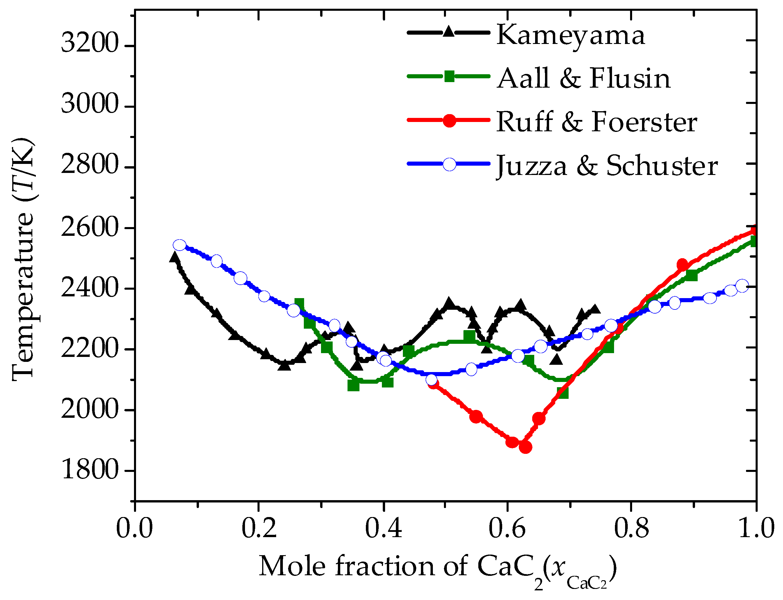
Stals [19] measured and calculated the three-phase equilibrium in sulfur dioxide + p-toluidine binary. However, the CaC2-CaO liquid–solid phase heterogeneous reaction equilibrium system has not been studied extensively, mainly because the eutectic temperature of the CaC2-CaO binary system is extremely high and the melt cannot be easily observed. In 1923, Ruff and Foerster [20] reported that the eutectic temperature of the CaC2-CaO binary system is 1910 K, and the mole fraction of CaC2 is 0.62. Flusin and Aall [21] found that CaC2 and CaO could form a eutectic of CaC2·CaO at 2253 K. In this system, there are two eutectic points. One of them is at 2023 K when the mole fraction of CaC2 is 0.68, and the other is at 2073 K when the mole fraction of CaC2 is 0.356. Li [22] measured the reaction activation energy of R2 by the so-conversional method and found that it was 213 kJ/mol when the temperature is higher than 1971 K but 477 kJ/mol when the temperature is below 1971 K. He attributed this relatively large difference to a predicted eutectic point of the CaC2-CaO mixture at 1971 K. Kameyama [23] introduced the production of CaC2 from CaO and C and he proposed that, above 1200 K, the interdiffusion between CaO and C occurs to form the solid CaO·C and CaC2 gradually and that CaC2 and CaO could form four eutectics of CaC2·CaO between 2100–2200 K. Juzza and Schuster [24] measured the liquid temperature of a CaC2 + CaO mixture system using optical pyrometry in 1961. They used CaC2 synthesized from metallic Ca and C in a Fe crucible. The reported impurities in the CaC2 were small amounts of CaO. The samples were not in contact with graphite during the experiments but were instead placed on titanium carbide to reduce the interaction of carbon with the sample. The time of the heating of the samples and the observation of the melting temperature were limited to reduce the possible evaporation of the sample. The reported phase diagram is for a simple eutectic binary system with a eutectic point at a CaC2 mole fraction of 0.48 and 2103 K. The results from all studies are summarized in Figure 1. Muller [7] argued that the work of Juzza and Schuster is the most reliable of all of the studies cited, and, thus, most researchers used the data of Juzza and Schuster in subsequent studies.
In the CaC2 manufacturing process, coke (88% C) and lime (92% CaO) entering from the top of the oxy-thermal carbide furnace react with oxygen entering from the bottom. A part of the coke combusts to release heat, driving the furnace temperature above 2200 K, and the CaO reacts with another part of the coke to produce CaC2. Based on the work of Muftah [17], Guo [18] showed that the reaction in the oxy-thermal carbide furnace is a gas–solid reaction system, and thus the system can be simplified as a C-O-Ca reaction system after the impacts of impurities, such as iron oxide, aluminum oxide, and silicon oxide, on the reactions in the furnace are ignored. Guo concluded that the CaC2 formation temperature is 1755 K, and he proposed a four-stage reaction process with the increase of temperature in the furnace: a combustion stage, the formation stage of CaC2, the equilibrium stage of CaC2, and a decomposition stage. The results indicate that, during the combustion stage, adding an appropriate amount of C is favorable for CO2 formation, as it improves the reaction heat supply ability of the exothermic combustion reaction and decreases feed consumption. During the formation stage of CaC2, the appropriate parameters of C addition, temperature, and pressure are 10.7 mol, 2473.15 K, and 100 kPa, respectively. However, he ignored the liquid phase in the furnace.
Ji [25] studied the CaC2 formation mechanism focusing on R2 and R3. He supposed that the different reaction mechanisms reported in the literature result from the differences in reaction pressure and temperature, and thus they do not contradict each other. At temperatures higher than 1573 K, CaC2 forms directly from CaO and coke. The result shows that the initial C/CaO ratio influences the reaction mechanism. An initial C/CaO ratio of less than three results in a three-stage mechanism, whereas an initial C/CaO ratio greater than three results in a two-stage mechanism. The suggested optimum conditions are approximately 253.3 kPa at 2200–2273 K and 405.3 kPa or higher at 2373 K.
This work aims to reveal the chemical reaction equilibrium behaviors of gas–liquid–solid heterogeneous phases in an oxy-thermal carbide furnace. To this end, the CaC2 formation mechanism was studied. In addition, the chemical reaction equilibrium behaviors of the gas–liquid–solid heterogeneous phases were analyzed at conditions of excess C and limited C.

2. Basic Thermodynamic Behavior of the Chemical Reaction System

Li [26] reported that magnesium oxide, iron oxide, and other minerals, such as calcium fluoride, in the furnace have only a slight influence on the CaC2 formation, and the minimal silicon oxide and aluminum oxide can only favor the pathway of R2 to produce CaC2. Thus, the reaction system can be simplified as the reaction system described in Guo’s work [18].
In the oxy-thermal carbide furnace at different temperature and pressure conditions, different reactions exist among O2, C, and CaO. In addition to R1, R2, and R3 shown as Equations (1)–(3), respectively, there are two other reactions, R4 and R5, which are shown in Equations (4) and (5), respectively. However, the reactions are not independent, and they tend not to exist simultaneously under a single set of temperature and pressure conditions:
2C + O2 = 2CO,
CaC2 + 2CaO = 3Ca + CO.
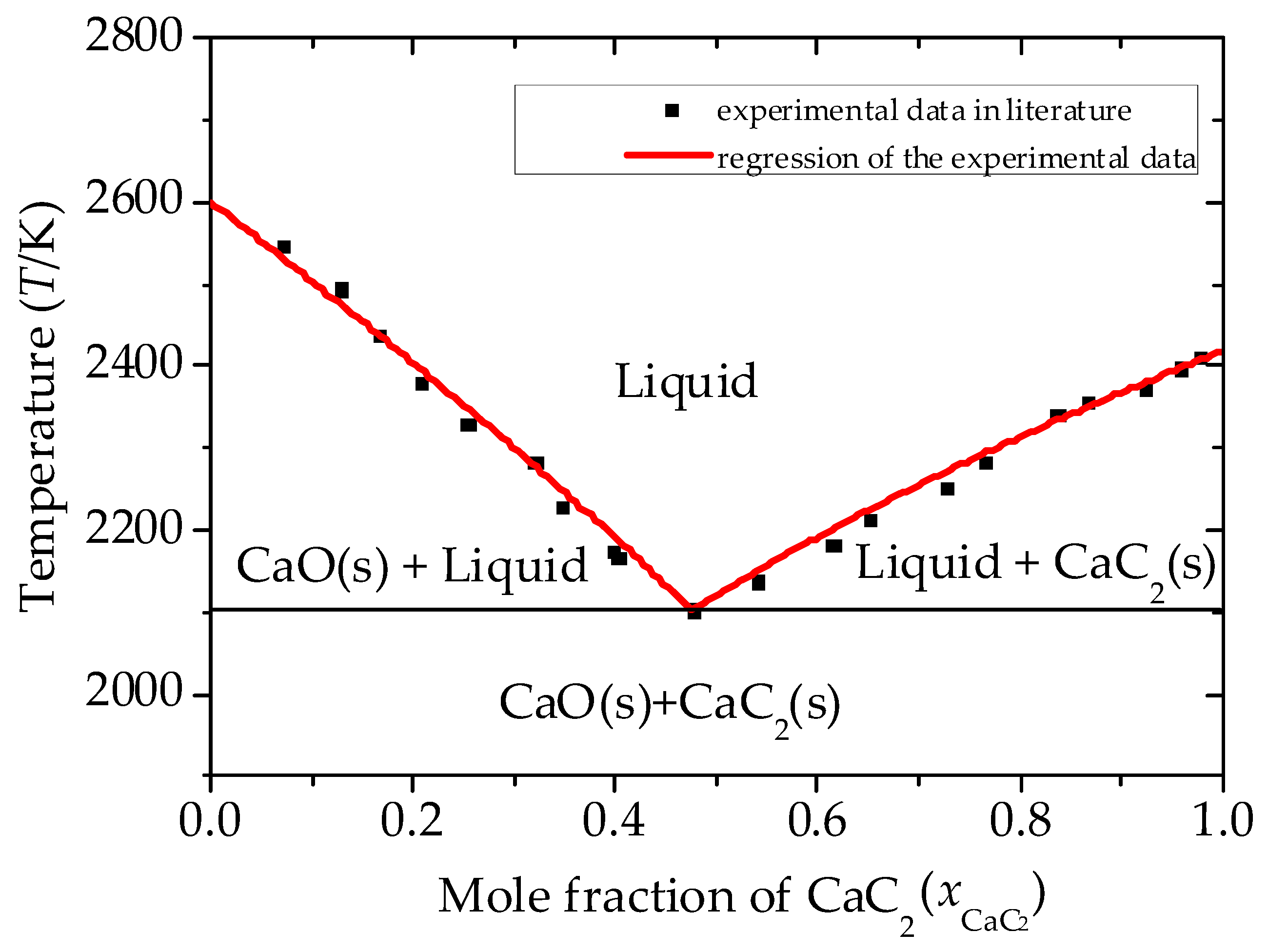
The phase diagram of the CaC2-CaO binary system is drawn in Figure 2 based on the data measured by Juza and Schuster. Then, Equations (6) and (7) were obtained using the solid–liquid two-phase equilibrium basic model [27] to regress the experimental data:
T 1 = 7627.57 ln ( 1 x CaC 2 ) 2.94 ,
T 2 = 11,923.50 ln x CaC 2 4.93 ,
x CaC 2 = 0.49 when T1 = T2 = 2103.4 K.
The liquid region is a mixture of CaC2 (L) and CaO (L), the liquid + CaO (s) region is a mixture of CaC2 (L), CaO (L), and CaO (s), and the liquid + CaC2 (s) region is a mixture of CaC2 (L), CaO (L) and CaC2 (s).

2.1. pVT Behavior of the Gas Phase

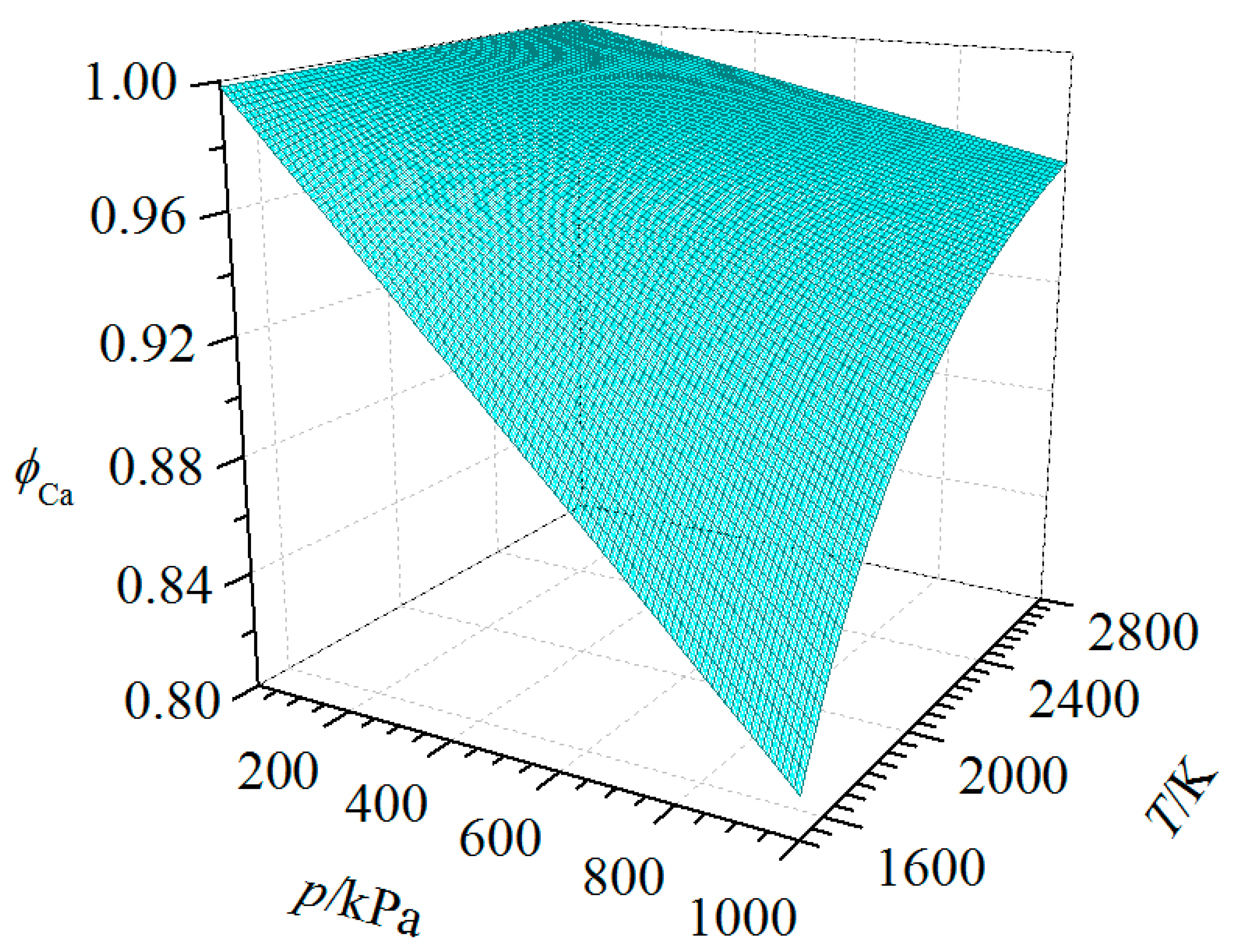
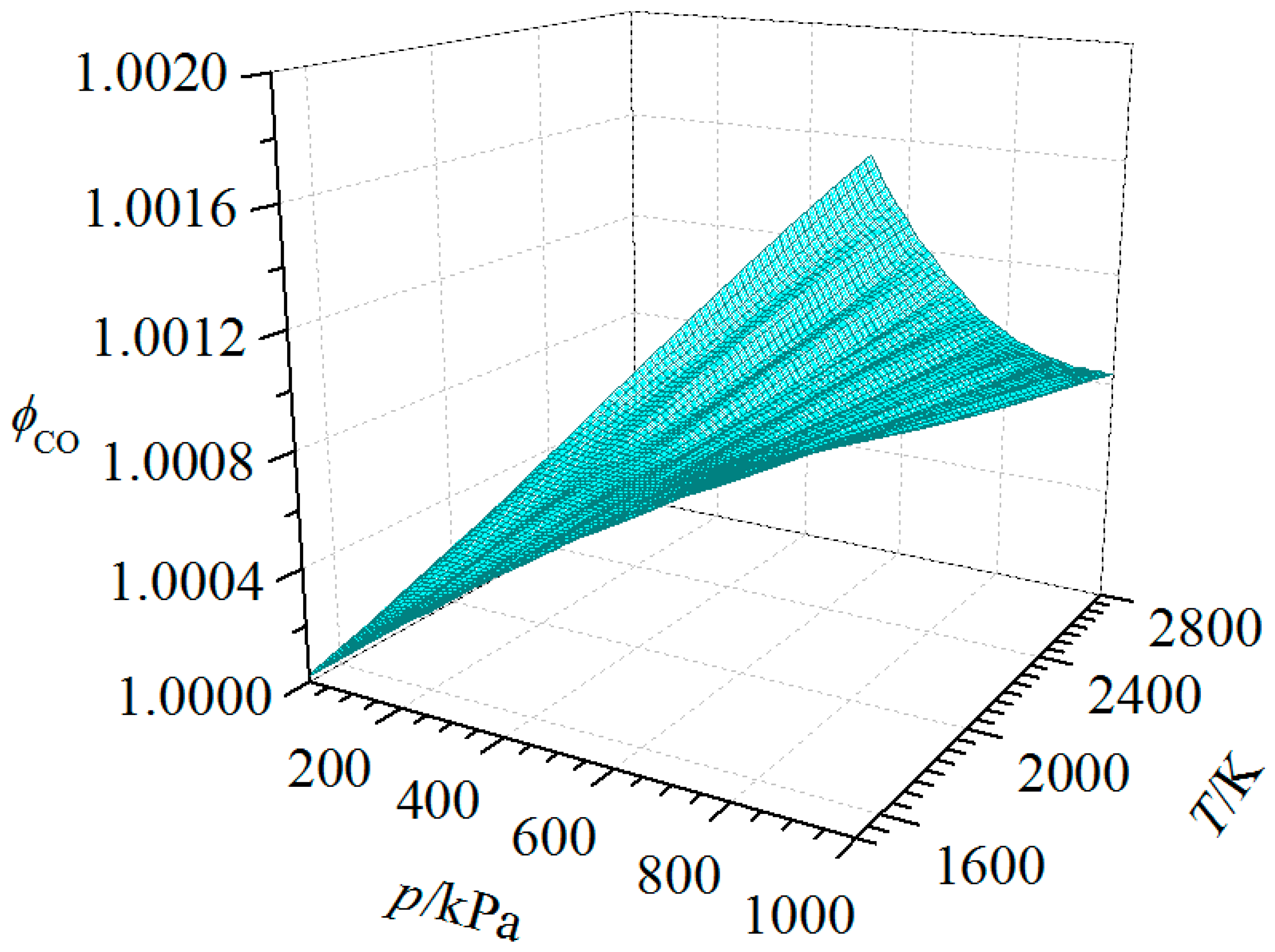
Assuming that the Peng–Robinson [28] Equations (8)–(11) can describe the pVT behavior of the gas phase in the oxy-thermal carbide furnace, the relationship of fugacity coefficient change with the temperature and pressure of Ca, CO and O2 are shown as Figure 3, Figure 4 and Figure 5, as calculated by Aspen plus technology software [29]:
p = R T V b α ( T , ω ) V ( V + b ) ,
b = 0.07779 R T c p c ,
α ( T , ω ) = [ 1 + ( 0.37464 + 1.54226 ω 0.26992 ω 2 ) ( 1 T r 1 2 ) ] 2 ,
T r = T T c ,
where the term (p, T, V) represents the specified state at pressure, temperature, and volume, respectively. The term (pc, Tc, ω, R) stands for the specified state at critical pressure, critical temperature, acentric factor, and thermodynamic constant, respectively, which could be obtained from the literature [30] for each substance.
Figure 3 is clearly different from Figure 4 and Figure 5. In the range of 1500–2800 K and 10–1000 kPa, ϕi of Ca is below 1 and decreases with increasing temperature and decreasing pressure, whereas ϕi of CO and O2 are above 1, and they increase with increasing temperature and decreasing pressure. ϕi of Ca deviates further from 1 than ϕi of CO and O2, which means that temperature and pressure have greater effects on the non-ideal behavior of Ca than on CO and O2.
Summarizing Figure 3, Figure 4 and Figure 5, the properties of CO and O2 approach those of an ideal gas because ϕi of CO and O2 do not deviate far from 1, whereas Ca cannot be treated as an ideal gas because ϕi of Ca deviates significantly from 1. Thus, the Peng–Robinson equation can be adopted to describe the gas properties of each gas in the furnace instead of the ideal gas equation.

2.2. Thermodynamic Equilibrium of the Reaction System

In the oxy-thermal carbide furnace, because there are small amounts of CaO, CaC2, and C in the gas phase and small amounts of CO, Ca, and O2 in the liquid phase, they can be ignored. Thus, the ratio between the gas phase and liquid phase is assumed to be mainly determined by the chemical reaction equilibrium. The partial pressure of O2 in the system is set at 100 kPa based on the industrial data since O2 is inputted into the system to react with C to provide heat and energy in the industrial production of CaC2. The mass of CO2 accounts for 0.98% of the off-gas in the industrial production process of CaC2, and the percentage of CO is above 90% [4,18], which demonstrates the slight formation of CO2 in the system. Thus, the influence of CO2 can be ignored in this work.
In the oxy-thermal carbide furnace, the occurrence of each reaction depends on the temperature and pressure. The thermodynamic property data of the substances in the furnace are listed in Table 1, which are compiled from several references [31,32,33] after evaluation in Guo’s work [18] and Li’s work [22].
For each component i in the furnace, entropy, enthalpy and Gibbs energy could be obtained by Equations (12)–(15):
S i θ ( T ) = S i , 298.15 K θ + 298.15 T C p , i T d T ,
H i θ ( T ) = H i , 298.15 K θ + 298.15 T C p , i d T ,
G i θ ( T ) = H i θ ( T ) + T S i θ ( T ) .
In addition, for each possible reaction j in the furnace, reaction Gibbs energy could be calculated by Equation (15):
Δ G j ( T , p ) = i v j , i G j , i θ ( T ) + R T ln i ( i y i p P θ ) v j , i ,
where vj,i is stoichiometric coefficient of component i in reaction j, and yi is the mole fraction of component i in the gas phase.
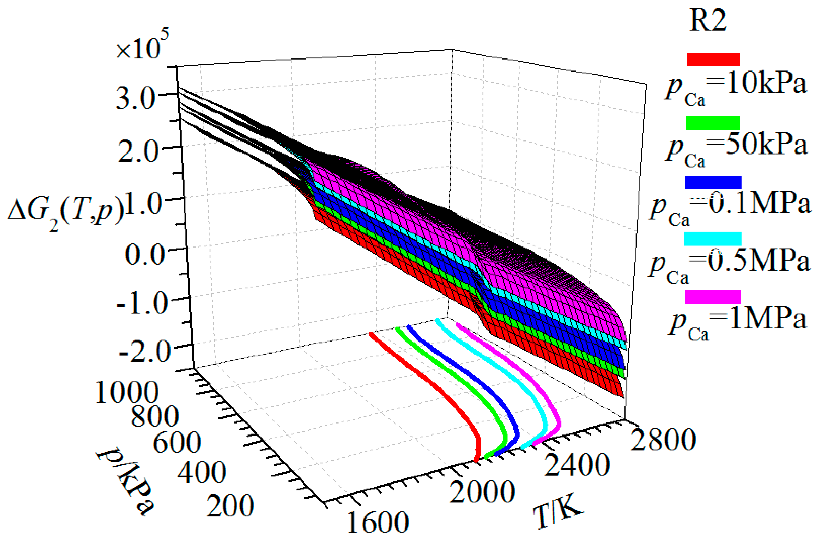
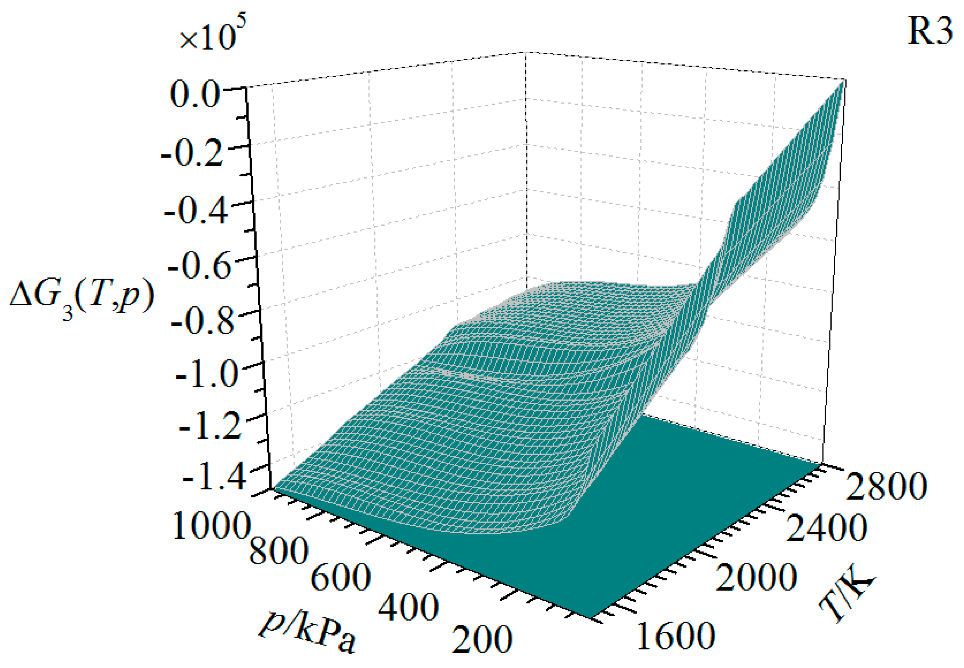
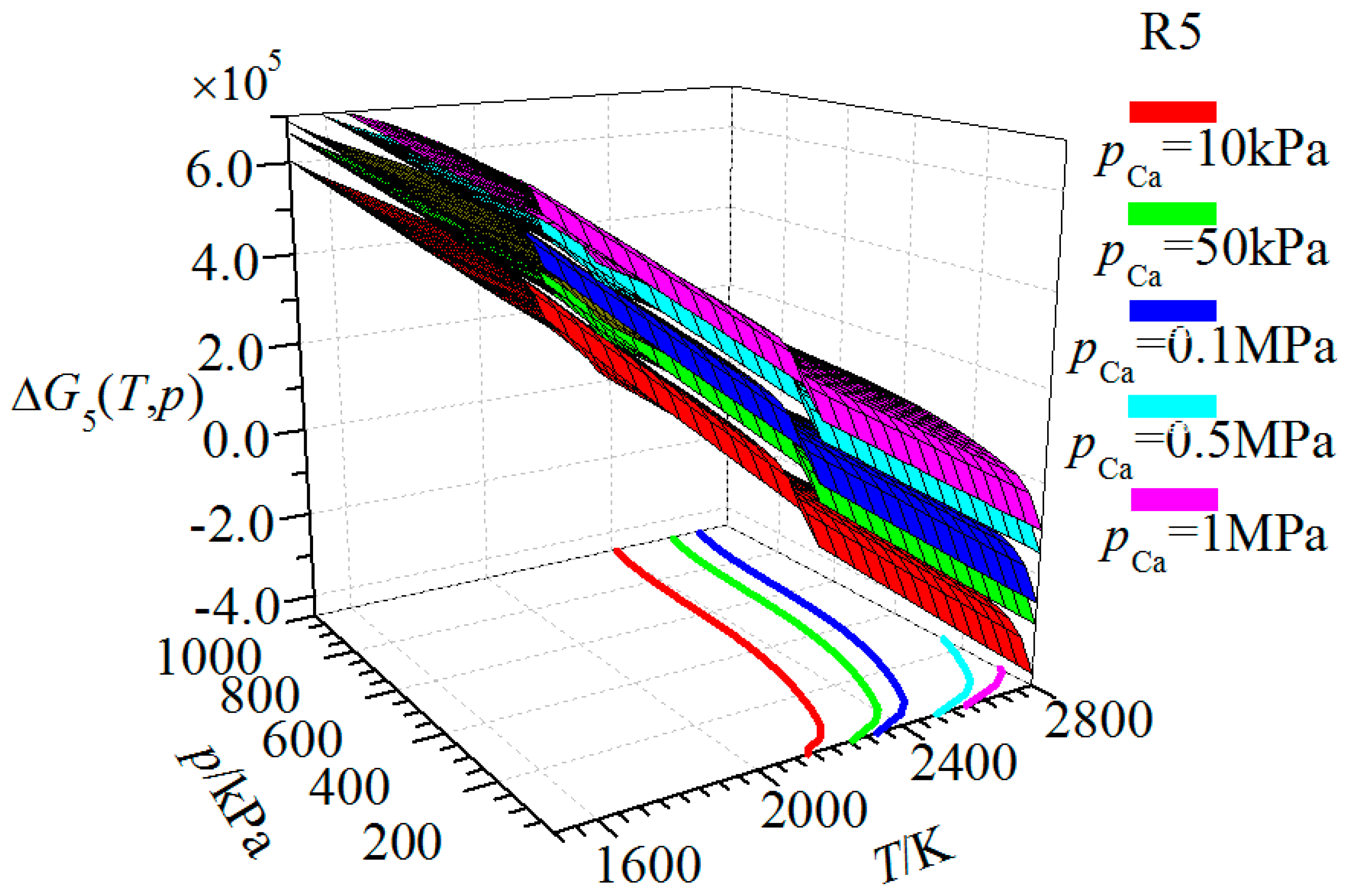
According to the thermodynamic property data and the equation models above, ΔGj-T-p plots are shown in the following figures.
The figures above express the relationship of each reaction ΔGj(T,p) with T and pCO in the furnace. The curved surfaces are the behavior surfaces of ΔGj(T,p), which is the surface corresponding to the Gibbs energy of the reaction j at a given temperature and pressure, and colored areas on the T-pCO coordinate are the shadow of ΔGj(T,p) ≤ 0. The lines on the T-pCO coordinate are the shadows of ΔGj(T,p) = 0, which indicate that the equilibrium of the reaction starts to shift towards the formation of products, creating the reaction products. The irregular inflections to form bulges on the behavior surfaces are caused by the eutectic of CaC2 and CaO mixture above the temperature of 2103.4 K.
Figure 6 shows the relationship of the ΔG1(T,p) behavior surface of R1 with T and pCO. When ΔG1(T,p) = 0, the shadow on the T-pCO coordinate is a boundary line of the shadow part. The boundary line indicates that ΔG1(T,p) = 0 and that the required temperature of R1 gradually drops as pCO decreases within the range of 1500–2800 K and 10–1000 kPa. When pCO is 10 kPa, the temperature of ΔG1(T,p) = 0 is at a minimum value of 1950.0 K.
Figure 7 shows the relationship of the ΔG2(T,p) behavior surface of R2 with T and pCO. The curve lines on the T-pCO coordinate are the shadows of ΔG2(T,p) = 0 at different pCa values, which means that the equilibrium of the reaction shifts to the formation of products. When ΔG2(T,p) = 0, the temperature at which the equilibrium of R2 shifts towards the formation of products decreases as pCO and pCa decrease. When pCO and pCa are 10 kPa, the temperature of ΔG2(T,p) = 0 is at its lowest value of 2100.0 K.
Figure 8 shows the relationship of the ΔG3(T,p) behavior surface of R3 with T and pCa. The ΔG3(T,p) of R3 is always below 0 in the range of 1500–2800 K and 10–1000 kPa. Thus, before reaching equilibrium, R3 shifts towards the formation of products, i.e., as long as Ca and C are present, they will react to produce CaC2. In other words, the reverse reaction of R3 will only shift towards the formation of initial substances. This is in opposition to previous reports in the literature [18,25]. According to the analysis above, in the condition range of 1500–2800 K and 10–1000 kPa, Ca can easily react with C to produce CaC2, but CaC2 can hardly decompose.
Figure 9 shows the relationship of the ΔG4(T,p) behavior surface of R4 with T and pCO. It indicates that the ΔG4(T,p) of R4 is always below 0; thus, in the condition range of 1500–2800 K and 0–1000 kPa, before reaching equilibrium, R4 shifts towards the formation of the products, i.e., C reacts with O2 to produce CO.
Figure 10 shows the relationship of the ΔG5(T,p) behavior surface of R5 with T and pCO. The curved lines on the T-pCO coordinates are the shadows of ΔG5(T,p) = 0, which means that the reaction starts to shift to the formation of products. When ΔG5(T,p) = 0, the temperature at which the equilibrium of R5 shifts towards the formation of products decreases as pCO and pCa decrease. When pCO and pCa are 10 kPa, the temperature of ΔG5(T,p) = 0 is at its lowest value of 2150.0 K.
Integrating R2, R3, and R5 shows that both R2 and R5 could create Ca at some T and pCO, but whether Ca presents in the system as the equilibrium approaches depends on R3. According to the analysis above, as long as C and Ca are present in the reaction system, the equilibrium of R3 will shift to the formation of CaC2. However, the amount of C is determined by the initial composition of the system, so, if there is an excess of C, the Ca from R2 and R5 will react with C and form CaC2 at any values of T and pCO before reaching equilibrium. Therefore, when reaching equilibrium, Ca does not exist in the system. Conversely, if the initial amount of C is insufficient, C will be consumed by R2 and R5 when approaching equilibrium and Ca will be present in the system.
In summary, whether Ca presents in the equilibrium system or not depends on T, pCO, and the initial quantity C.
In the practical manufacture of CaC2, the operating pressure in the oxy-thermal carbide furnace is typically approximately 101.3 kPa. Taking 101.3 kPa as the pressure condition in the following discussion, when ΔGj(T,p) = 0, the equilibrium of reaction j starts to shift to the formation of products. C initially reacts with O2 according to R4 to release heat, and the furnace is heated. As the temperature increases in the furnace, the first reaction to occur is R1, and, at this point, the temperature is 2090.0 K and CaC2 is produced in the furnace. When the temperature reaches 2360 K, R2 begins to produce Ca and CO, but the Ca will react with C to form CaC2 through R3. When the temperature increases to 2490.0 K, R5 occurs, and the CaC2 will decompose to produce Ca and CO with the participation of the CaO.

3. Equilibrium Composition in the Oxy-Thermal Carbide Furnace

Considering a system with multiple components and heterogeneous phases at constant temperature and pressure, there are chemical reactions and mass transfer among the phases before the system reaches equilibrium. At this point, the state change in the system is irreversible, which tends to make the system reach equilibrium. If Gt is expressed as the function of the amount of each component in the heterogeneous phases under the mass conservation law, there is an amount of each component that can minimize Gt, and this is the effective method to solve problems in a system of multiple components and heterogeneous phases, such as in an oxy-thermal carbide furnace. Ignoring the influence of minerals, such as iron oxide, aluminum oxide, and silicon oxide, Equations (16)–(18) can be applied to the oxy-thermal carbide furnace according to Gibbs energy theory [34,35]:
G min t = n i g G i ( T ) + n i g R T ln y i ϕ i p i p θ + n i l G i ( T ) + n i l R T ln x i + n i s G i ( T ) ,
y i = n i g n i g ,
x i = n i l n i l .
Considering a reaction system composed of M elements and N components, Am is the number of the mth atom and Bi the molar quantity of the ith component. aim is the number of the mth atom of the ith component, which is the atomic coefficient. There is
A m = i a i , m B i ( i = 1 , 2 , N , m = 1 , 2 , M ) .
In this work, it is assumed that there is chemical equilibrium in the oxy-thermal carbide furnace between the gas, liquid, and gas solid phases, whereas the gas–liquid and gas–solid phase equilibrium and adsorption can be ignored. In addition, when the liquid and solid phases reach equilibrium, Equation (20) can be obtained as follows:
n CaC 2 l n CaC 2 s = x CaC 2 s x CaC 2 x CaC 2 x CaC 2 l .
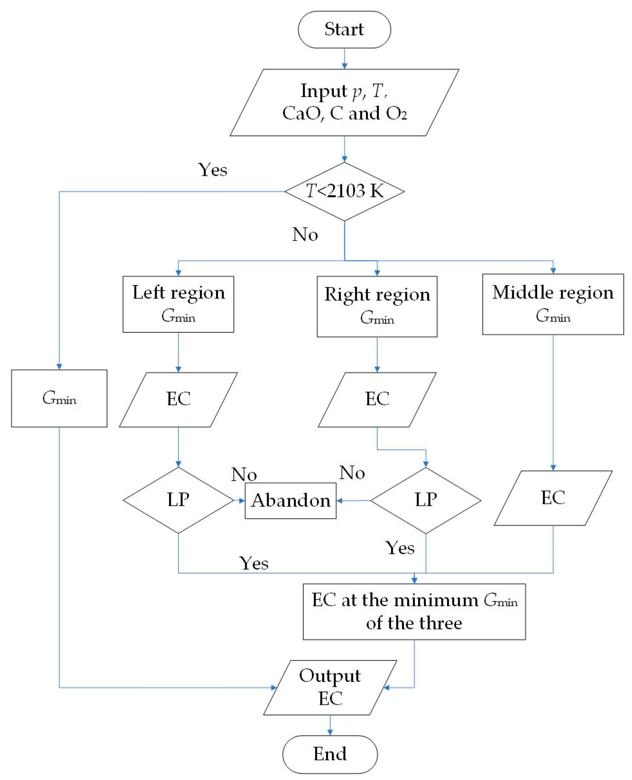
Figure 11 is the calculation flow diagram of equilibrium components of the system. In this diagram, the left region, right region and middle region represent the liquid + CaO (s) region, the liquid + CaC2 (s) region, and the liquid region in Figure 2, respectively. EC stands for equilibrium components and LP means lever principle. Gmin is the minimum Gibbs energy of the system at each condition.

3.1. Analysis of the Equilibrium Composition under Conditions of Excess C

As discussed in Section 2, the amount of C present has an effect on the presence of Ca. When C is present in excess, the produced Ca can quickly react with C to form CaC2. Therefore, there is no Ca in the system when the system reaches equilibrium. In contrast, Ca will persist in the system when C is limited, so there is Ca when the system reaches equilibrium. Therefore, the amount of C in the system should be considered when studying the equilibrium composition. After energy coupling calculation, the appropriate initial amounts of CaO, O2 and C are 1, 2.5 and 7.5 mol, respectively. Based on this theory, different equilibrium compositions are obtained under excessive C and limited C conditions.
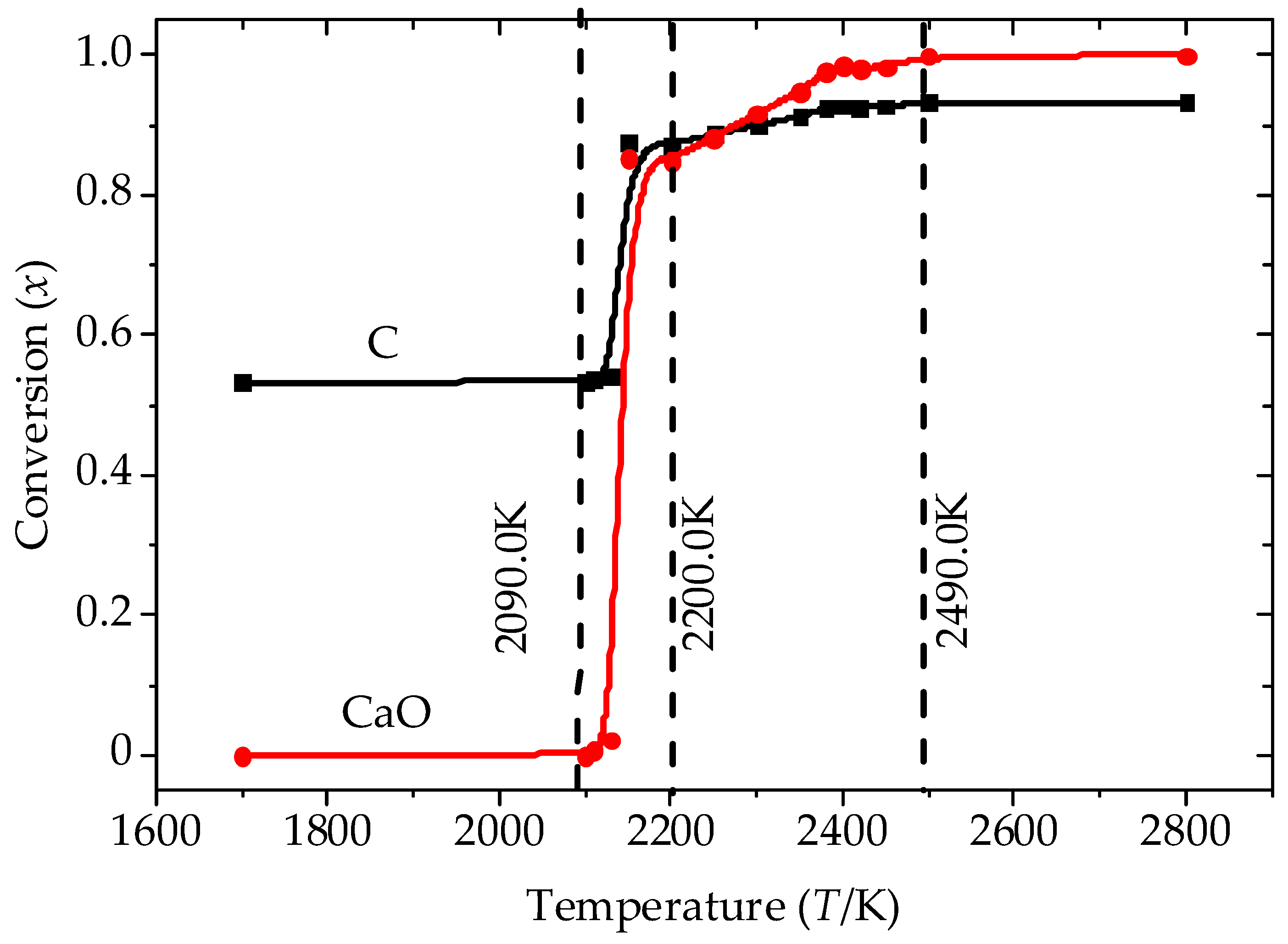
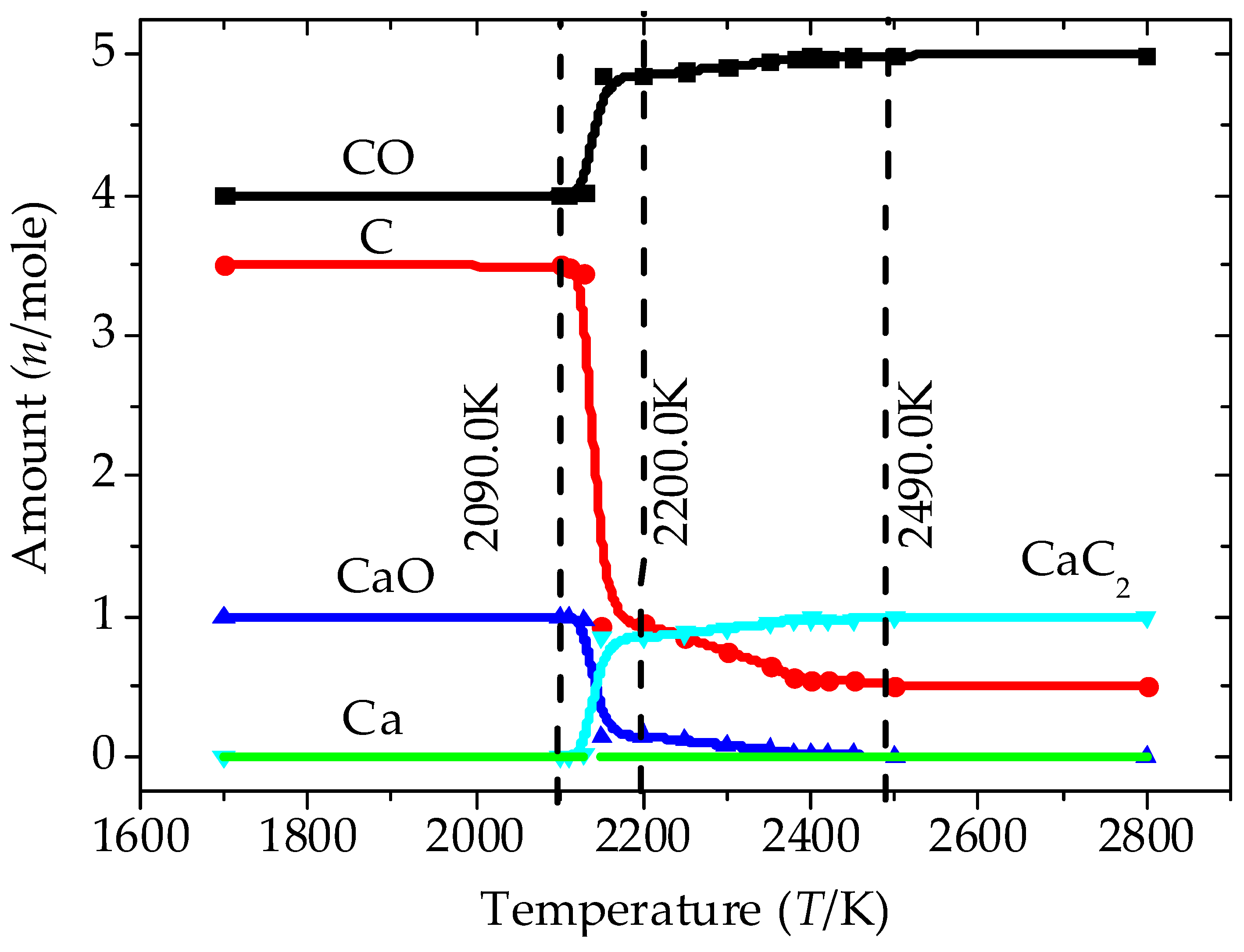
At 100 kPa, 1 mol of CaO, 2.5 mol of O2, and 7.5 mol of C are added to the oxy-thermal carbide furnace. Figure 12, Figure 13 and Figure 14 were obtained by the calculation of MathCAD software (version 15, Parametric Technology Corporation, Boston, MA, USA) based on the equations and theory above. Figure 12 presents the conversions of CaO and C at each reaction temperature. Figure 13 expresses the equilibrium composition with temperature. Figure 14 illustrates the equilibrium phase composition with temperature.
Figure 12 and Figure 13 indicate that, in the temperature range of 1600–2800 K, O2 is completely consumed to produce CO. At 2090 K, C and CaO reduce sharply to produce CaC2 and CO, i.e., the conversions increase, which matches the discussion in Section 2. With the increase of temperature, CaO and C gradually decrease and the conversion increases to 100% and 99% and CaC2 increases to 1 mol. In the temperature range of 1700–2800 K, the amount of Ca is zero throughout because of the excess C and the pressure not being conducive to the formation of Ca. This result is also consistent with the discussion in Section 2.
Figure 13 shows the chemical reaction equilibrium behavior of gas–liquid–solid heterogeneous phases in the condition of excess C in the oxy-thermal carbide furnace. At approximately 2100 K, CaC2 is produced to form a eutectic with CaO, which matches the description in Figure 12. CaO (L) and CaC2 (L) increase with increasing temperature. At approximately 2200 K, CaC2 (L) reaches a peak and then gradually diminishes. This trend can be explained by Figure 12. When the reaction occurs, the amount of CaC2 gradually increases, and the equilibrium composition state of CaC2 in the system moves from the Liquid + CaO (s) region directly to the Liquid + CaC2 (s) region. This leads to the decrease of CaC2 and the conversion of CaO, appearing as the peak in Figure 14. Due to CaO (s) rapidly disappearing after the reaction occurs at approximately 2200 K, CaC2 (s) has a peak and then increases slowly, but, at approximately 2400 K, CaC2 (s) decreases sharply because the mole fraction of CaC2 is close to 1 and the temperature reaches the melting point of CaC2, which is 2400 K.
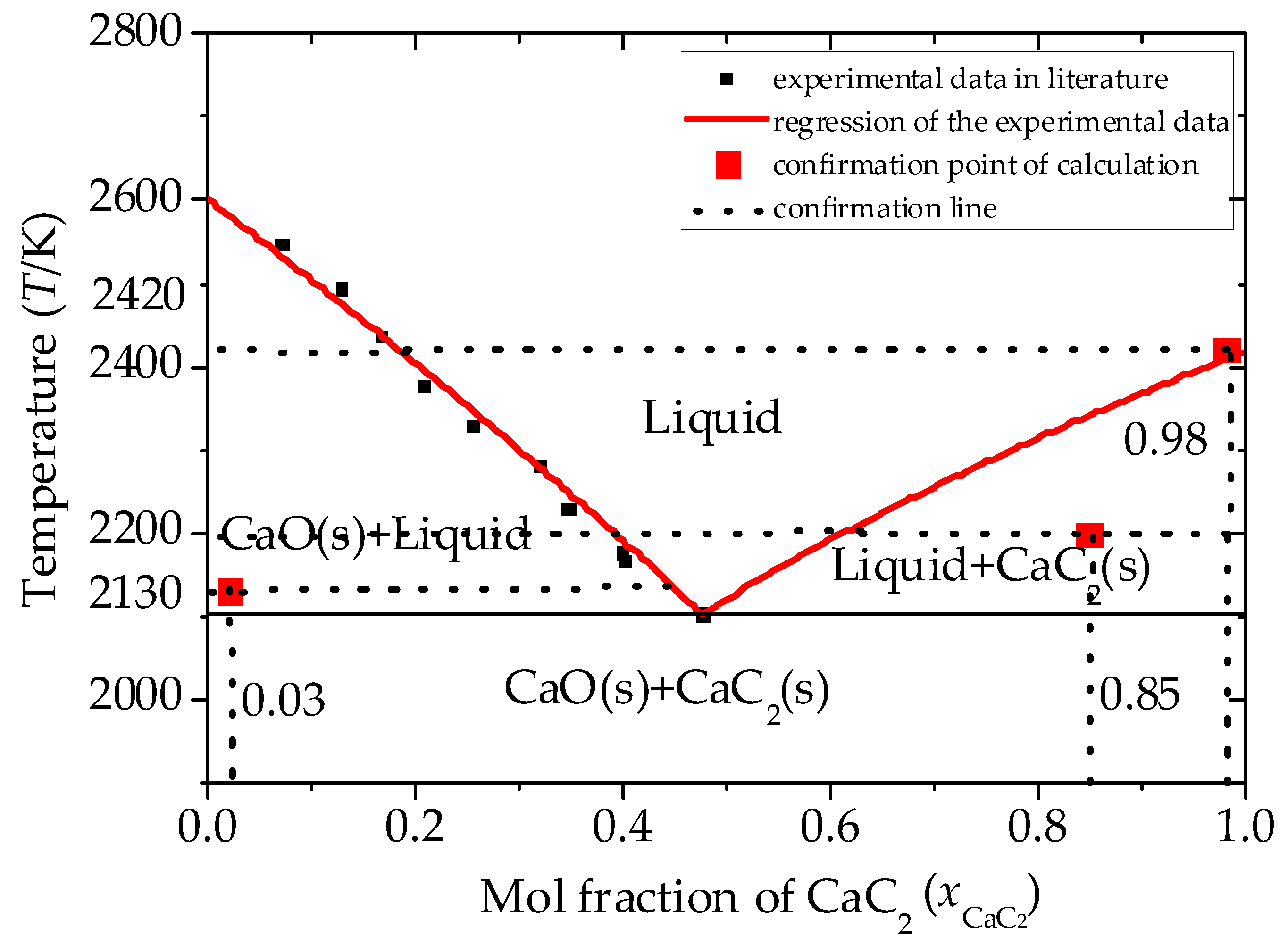
To validate the equilibrium components, confirmation of the calculation was made as shown in Figure 15. The system equilibrium components are illustrated at three different temperature conditions, which are 2130 K, 2200 K, and 2420 K. At 2130 K, the system point is in the liquid + CaO (s) region and xCaC2 is 0.03. At 2200 K, the system point is in the liquid + CaC2 (s) region with the xCaC2 of 0.85. However when the temperature reaches 2420 K, the system point is in the liquid region, and the xCaC2 is 0.98.

3.2. Analysis of the Equilibrium Composition at a Condition of Limited C

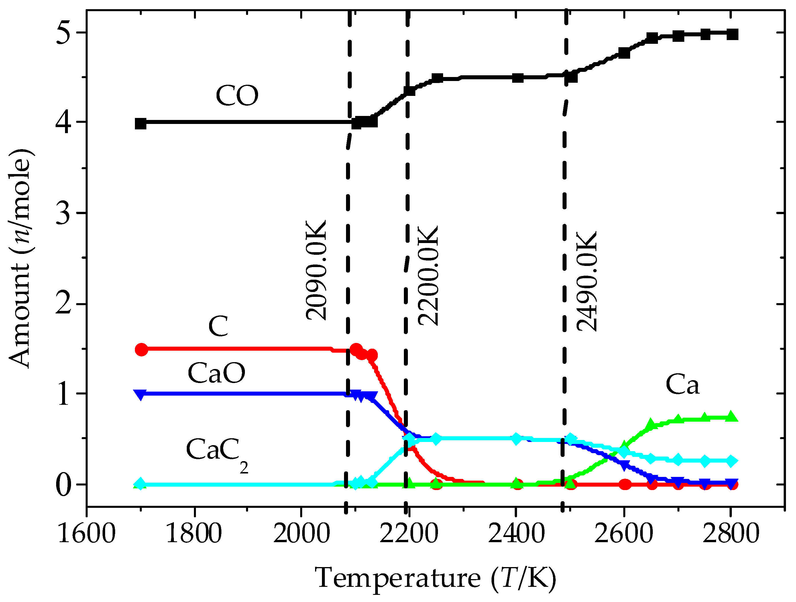
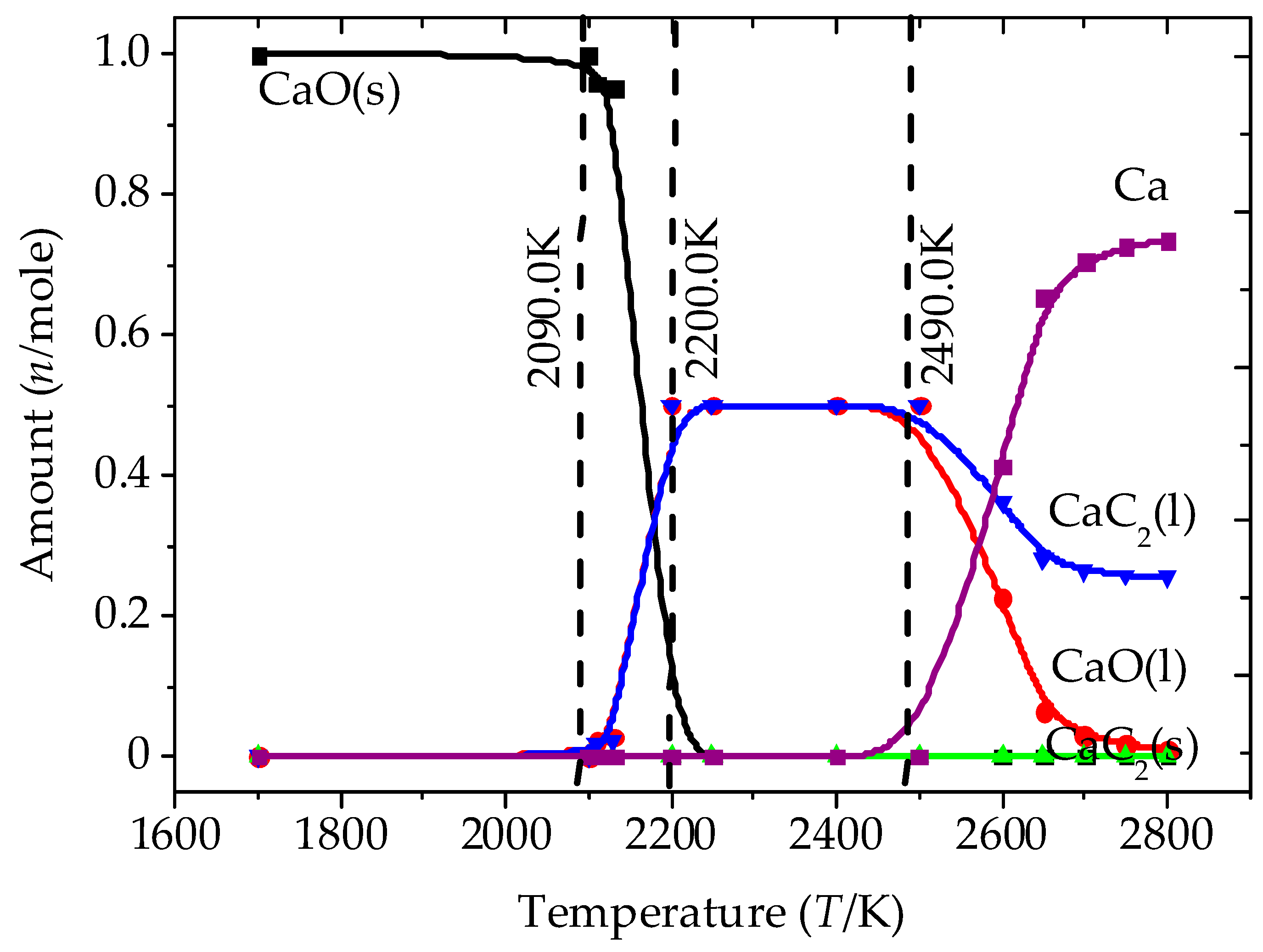
Figure 16, Figure 17 and Figure 18 were obtained under the conditions of a pressure of 100 kPa and a composition of 1 mol of CaO, 2.5 mol of O2, and 5.5 mol of C in the oxy-thermal carbide furnace.
Figure 16 and Figure 17 show that, at approximately 2100 K, CaO starts to react with C to produce CaC2. CaO and C gradually decrease, whereas the conversion of CaO and C increases. CaC2 reaches a maximum at approximately 2200 K. After 2290 K, the C is completely consumed, but CO, CaC2 and CaO remain the same. After approximately 2490 K, CaO gradually diminishes, and Ca is rapidly produced. Then, the conversion of CaO is further enhanced to 100% at 2800 K.
Figure 18 shows the chemical reaction equilibrium behavior of the gas–liquid–solid heterogeneous phases under the limited C condition in the oxy-thermal carbide furnace. With the increase of temperature, CaO (s) begins at its maximum, with an initial concentration of 1 mol. When the reaction occurs, CaO (s) quickly melts and decreases to zero, whereas CaO (L) and CaC2 (L) increase. At approximately 2200 K, CaO (L) and CaC2 (L) are nearly identical, with approximate maximums of 0.5 mol and then remain the same afterward. This is because the mole fraction of CaC2 in the system is within the liquid region in Figure 2. At 2490 K, CaO (L) and CaC2 (L) decrease gradually, but Ca increases rapidly due to R5 shifting to the formation of products at this temperature, producing a large amount of Ca.
Figure 12, Figure 13, Figure 14, Figure 15, Figure 16, Figure 17 and Figure 18 illustrate that the maximum conversion of CaO to CaC2 is 50% in the limited C condition. After 2490 K, R5 occurs, which means that CaC2 is consumed to react with CaO to produce Ca. Therefore, the excess C condition should be adopted in the practical manufacture of CaC2. For example, at the condition of excess C and approximately 2370 K, CaC2 (L) increases and CaO (s) decreases rapidly with temperature. Meanwhile, the conversions of CaO and C reach 90%. This may be considered as a set of appropriate operating conditions.

4. Conclusions

This study demonstrates that the CaC2 formation mechanism depends on two factors, the amount of C and the CO partial pressure. When the C is in excess and the CO partial pressure is high, the production of Ca is limited; thus, the CaC2 formation is believed to be a one-step mechanism. However, when there is limited C and the CO partial pressure is low, the production of Ca is promoted; thus, CaC2 formation is believed to be a two-step mechanism.
The chemical reaction equilibrium behaviors of gas–liquid–solid heterogeneous phases in an oxy-thermal carbide furnace were analyzed at conditions of an excess of C and limited C. At 100 kPa, the equilibrium compositions in the furnace were calculated at different temperature conditions, and approximately 2370 K and 100 kPa is an appropriate condition for the formation of CaC2. Under these conditions, the conversions of both CaO and C can reach 90%.

Author Contributions

W.X., D.Z., X.C., and W.H. conceived the study. Q.W. analyzed data and made figures. M.G. and Y.M. provided resources for this work. W.X. wrote the paper and all authors contributed to the editing of the manuscript. All authors have read and agreed to the published version of the manuscript.

Funding

This research received no external funding.

Acknowledgments

This work was supported by the National Basic Research Program of China (2011CB201306), the GDAS Special Project of Science and Technology Development) (Grant No. 2018GDASCX-0802), and the National Natural Science Foundation of China (51706146). Wenjie Xiong wishes to acknowledge the support from Beijing University of Chemical Technology, Beijing 100029, China, for obtaining his Master’s degree in 2015.

Conflicts of Interest

The authors declare no conflict of interest.

References

  1. Szmant, H. Organic Building Blocks of the Chemical Industry; John Wiley & Sons. Inc.: Hoboken, NJ, USA, 1989; pp. 255–256. [Google Scholar]
  2. Sun, W. Reviews of the calcium carbide industry in 2012 and prospect in 2013. Econ. Anal. China’s Pet. Chem. Ind. 2013, 4, 29–31. [Google Scholar]
  3. Erasmus, L. The application of plasma-arc technology for the production of calcium carbide. In Proceedings of the Electric Furnace Conference Proceedings, Toronto, ON, Canada, 12–15 November 1991; pp. 293–298. [Google Scholar]
  4. Guo, J.; Zheng, D.X. Thermodynamic analysis of low-rank-coal-based oxygen-thermal acetylene manufacturing process system. Ind. Eng. Chem. Res. 2012, 51, 13414–13422. [Google Scholar] [CrossRef]
  5. Mi, Y.; Zheng, D.X.; Guo, J.; Chen, X.H.; Jin, P. Assessment of energy use and carbon footprint for low-rank coal-based oxygen-thermal and electro-thermal calcium carbide. Fuel Process. Technol. 2014, 119, 305–315. [Google Scholar] [CrossRef]
  6. Tagawa, H.; Sugawara, H. The kinetics of the formation of calcium carbide in a solid-solid reaction. J. Ceram. Chem. Jpn. 1962, 35, 1276–1279. [Google Scholar] [CrossRef]
  7. Muller, M. Structure, properties and reactions of CaO in burnt lime. Part 3. Composite reactions of CaO and C in solid and liquid state. Scand. J. Metall. 1990, 19, 210–217. [Google Scholar]
  8. EI-Nass, M.; Munz, R. Production of calcium carbide in a plasma-jet fluid bed reactor. In Proceedings of the ISPC-12, Minneapolis, MN, USA, 21–25 August 1995; pp. 613–618. [Google Scholar]
  9. EI-Nass, M.; Munz, R.; Ajersch, F. Solid-phase synthesis of calcium carbide in a plasma reactor. Plasma Chem. Plasma Process. 1998, 18, 409–427. [Google Scholar] [CrossRef]
  10. Rai, H.; Gregory, N. The time dependence of effusion cell steady-state pressure of carbon monoxide and calcium vapors generated by the interaction of calcium oxide and graphite. J. Phys. Chem. 1970, 74, 529–534. [Google Scholar] [CrossRef]
  11. Brookes, C.; Gall, E.; Hudgins, R. A model for the formation of calcium carbide in solid pellets. Can. J. Chem. Eng. 1975, 53, 527–533. [Google Scholar] [CrossRef]
  12. Wiik, K.; Raaness, O.; Olsen, S. Formation of calcium from calcium vapor and carbon. Scand. J. Metall. 1983, 13, 1347–1354. [Google Scholar]
  13. Kim, S.; Raymond, F.; Baddour, B. CaC2 Production from CaO and coal or hydrocarbons in a rotating-arc reactor. Ind. Eng. Chem. Process Des. Dev. 1979, 18, 323–328. [Google Scholar] [CrossRef]
  14. Wang, J.; Kayoko, M.; Takayuki, T. High-temperature interactions between coal char and mixtures of calcium oxide, quartz and kaolinite. Energy Fuels 2001, 15, 1145–1152. [Google Scholar] [CrossRef]
  15. Thoburn, W.; Pidgeon, L. Differential thermal analysis of calcium carbide formation. Can. Metall. Q. 1965, 4, 205–217. [Google Scholar] [CrossRef]
  16. Li, G.D.; Liu, Q.Y.; Liu, Z.Y. Production of calcium carbide from fine biochars. Angew. Chem. Int. Ed. 2010, 49, 8480–8483. [Google Scholar] [CrossRef] [PubMed]
  17. Muftah, H. Synthesis of Calcium Carbide in a Plasma Spout Fluid Bed. Ph.D. Thesis, McGill University, Montréal, QC, Canada, 1996. [Google Scholar]
  18. Guo, J.; Zheng, D.X.; Chen, X.H.; Mi, Y.; Liu, Z.Y. Chemical reaction equilibrium behaviors of an oxy-thermal carbide furnace reaction system. Ind. Eng. Chem. Res. 2013, 52, 17773–17780. [Google Scholar] [CrossRef]
  19. Stals, J.; Peters, C.; Diepen, G. Measurements and calculation of the three-phase equilibrium (solid compound + liquid + gas) in the binary (sulfur dioxide + p-toluidine) where the compound in liquid and gas is dissociated into its components. J. Chem. Thermodyn. 1979, 11, 1107–1112. [Google Scholar] [CrossRef]
  20. Ruff, O.; Foerster, E. Calcium carbide, its formation and decomposition. Z. Anorg. Allg. Chem. 1923, 131, 321–347. [Google Scholar] [CrossRef]
  21. Flusin, G.; Aall, C. Sur l’étude du système CaC2-CaO. Compt. Rend. 1935, 201, 451–453. [Google Scholar]
  22. Li, G.D.; Liu, Q.Y.; Liu, Z.Y. Kinetic behaviors of CaC2 production from coke and CaO. Ind. Eng. Chem. Res. 2013, 53, 527–535. [Google Scholar] [CrossRef]
  23. Kameyama, N. Electrochemistry: Theory and Applications, Vol. III-2; Maruzen: Tokyo, Japan, 1956; pp. 134–141. [Google Scholar]
  24. Juza, R.; Schuster, H. The phase diagram of the calcium oxide-calcium carbide system. Z. Anorg. Allg. Chem. 1961, 311, 62–75. [Google Scholar] [CrossRef]
  25. Ji, L.M.; Liu, Q.Y.; Liu, Z.Y. Thermodynamic analysis of calcium carbide production. Ind. Eng. Chem. Res. 2014, 53, 2537–2543. [Google Scholar] [CrossRef]
  26. Li, G.D.; Liu, Q.Y.; Liu, Z.Y. CaC2 production from pulverized coke and CaO at low temperature – influence of minerals in coal-derived coke. Ind. Eng. Chem. Res. 2011, 51, 10748–10754. [Google Scholar] [CrossRef]
  27. Smith, J.M.; Van Ness, H.C.; Abbott, M.M. Introduction to Chemical Engineering Thermodynamics, 6th ed.; McGraw-Hill Co. Inc.: New York, NY, USA, 2001; pp. 390–476. [Google Scholar]
  28. Peng, D.Y.; Robinson, D.B. A new two-constant equation of state. Ind. Eng. Chem. Fundam. 1976, 15, 59–64. [Google Scholar] [CrossRef]
  29. Aspen Plus. Aspen Plus IGCC Mode; Aspen Technology: Bedford, MA, USA, 2008. [Google Scholar]
  30. Binnewies, M.; Milke, E. Thermodynamical Data of Elements and Compounds; Wiley-Vch Verlag GmbH: Weinheim, Germany, 2002. [Google Scholar]
  31. Barin, I. Thermochemical Data of Pure Substances, 3rd ed.; Wiley-Vch Verlag GmbH: Weinheim, Germany, 1995; pp. 422–441. [Google Scholar]
  32. Healy, G. The Calculation of an internal energy balance in the smelting of Calcium Carbide. J. S. Afr. Inst. Min. Metall. 1995, 9, 225–232. [Google Scholar]
  33. Lindberg, D.; Chartrand, P. Thermodynamic evaluation and optimization of the (Ca + C + O + S) system. J. Chem. Thermodyn. 2009, 41, 1111–1124. [Google Scholar] [CrossRef]
  34. Vonka, P.; Leitner, J. Calculation of chemical equilibrium in complex system: System restrictions. Collect. Czech. Chem. Commun. 2000, 65, 1443–1452. [Google Scholar] [CrossRef]
  35. Aljarrha, M.; Medraj, M. Thermsodynamic assessment of the phase equilibria in the Al-Ca-Sr system using the modified quasichemical model. J. Chem. Thermodyn. 2008, 40, 724–734. [Google Scholar] [CrossRef]
Sample Availability: Samples of the compounds are available from the authors.
Figure 1. Phase diagram of the CaC2-CaO binary system.
Chemengineering 04 00002 g001
Figure 2. Experimental data fitting of phase diagram of CaC2-CaO binary system (Liquid contains CaO (l) and CaC2 (l)).
Chemengineering 04 00002 g002
Figure 3. Fugacity coefficient of Ca.
Chemengineering 04 00002 g003
Figure 4. Fugacity coefficient of CO.
Chemengineering 04 00002 g004
Figure 5. Fugacity coefficient of O2.
Chemengineering 04 00002 g005
Figure 6. Gibbs energy dependence on temperature and CO partial pressure for reaction R1.
Chemengineering 04 00002 g006
Figure 7. Gibbs energy dependence on temperature and Ca and CO partial pressure for reaction R2.
Chemengineering 04 00002 g007
Figure 8. Gibbs energy dependence on temperature and Ca pressure for reaction R3.
Chemengineering 04 00002 g008
Figure 9. Gibbs energy dependence on temperature and CO partial pressure for reaction R4.
Chemengineering 04 00002 g009
Figure 10. Gibbs energy dependence on temperature and Ca and CO partial pressure for reaction R5.
Chemengineering 04 00002 g010
Figure 11. Calculation flow diagrams of the equilibrium components.
Chemengineering 04 00002 g011
Figure 12. The conversion of C and CaO at each reaction temperature.
Chemengineering 04 00002 g012
Figure 13. The equilibrium composition at each reaction temperature.
Chemengineering 04 00002 g013
Figure 14. The equilibrium phase composition at each reaction temperature.
Chemengineering 04 00002 g014
Figure 15. Confirmation of the calculation (Liquid contains CaO (L) and CaC2 (L)).
Chemengineering 04 00002 g015
Figure 16. The conversion of C and CaO at each reaction temperature.
Chemengineering 04 00002 g016
Figure 17. The equilibrium composition at each reaction temperature.
Chemengineering 04 00002 g017
Figure 18. The equilibrium phase composition at each reaction temperature.
Chemengineering 04 00002 g018
Table 1. Thermodynamic data H i , 298.15   K θ , S i , 298.15   K θ and C p , i of the components in the furnace.
SubstanceT H i , 298.15   K θ S i ,   298.15   K θ C p , i
KJ·mol−1J·mol−1·K−1J·mol−1·K−1
C (graphite)298.15–110005.740.084 + 0.038911 × T − 146,400 × T−2 − 0.000017364 × T2
1100–4073 24.435 + 0.000418 × T − 3,163,100 × T−2
O2 (g)298.15–30000205.0429.957 + 0.00418 × T − 167,400 × T−2
CO (g)298.15–2800−110,541197.52728.409 + 0.0041 × T − 46,000 × T−2
Ca (g)298.15–2800−178,146154.67420.832
CaO (s)298.15–2845−635,09037.7558.7912 − 1,147,146 × T−2 − 133.904 × T−0.5 + 102,978,787.9 × T−3
CaO (l)298.15–2845−555,59465.6958.7912 − 1,147,146 × T−2 − 133.904 × T−0.5 + 102,978,787.9 × T−3
CaC2 (s)298.15–1275−53,030.379.155364.4336 + 0.008368 × T
1275–3000 75.1028
CaC2 (l)298.15–30003802.296.82575.1028