Abstract
Levulinic acid (LA) has been ranked as one of the “Top 10” building blocks for future bio-refineries as proposed by the US Department of Energy. It is considered one of the most important platform molecules for the production of fine chemicals and fuels based on its compatibility with existing processes, market economics, and industrial ability to serve as a platform for the synthesis of important derivatives. Hydrogenation of LA to produce γ-valerolactone (GVL) is an active area of research due to the potential of GVL to be used as a biofuel in its own right and for its subsequent transformation into hydrocarbon fuels. This paper contains a new design for a simple, cost effective, and safe hydrogenation reactor for the transformation of levulinic acid to γ-valerolactone (GVL) by utilizing high boiling point organic fluid. The hydrogenation reactor is composed of a heating source—organic fluid (called “DOWTHERM A” or “thermex”) and the catalytic reactor. The advantages of high boiling temperature fluids, along with advances in hydrocracking and reforming technologies driven by the oil and gas industries, make the organic concept more suitable and safer (water coming in contact with liquid metal is well understood in the metallurgical industry to be a steam explosion hazard) for heating the hydrogenation reactor. COMSOL multi-physics software version 4.3b was applied in this work and simultaneously solves the continuity, Navier-Stokes (fluid flow), energy (heat transfer), and diffusion with chemical reaction kinetics equations. It was shown that the heat flux supplied by the DOWTHERM A organic fluid could provide the necessary heat flux required for maintaining the hydrogenation process. It was found that the mass fractions of hydrogen and levulinic acid decreased along the reactor axis. The GVL mass fraction increased along the reactor axis.
1. Introduction
The utilization of biomass for the production of fuel and chemicals has become an important research topic because of the growing concerns regarding the depletion of fossil carbon reserves and the environmental impact (such as air pollution) of our continued dependence on these resources [1]. Levulinic acid (LA) is ranked as one of the “Top 10” building blocks for future bio-refineries as proposed by the US Department of Energy [2]. It is considered as one of the most important platform molecules for the production of fine chemicals and fuels [3] based on its compatibility with existing processes, market economics, and industrial ability to serve as a platform for the synthesis of important derivatives. Hydrogenation of LA to produce γ-valerolactone (GVL) is an active area of research due to the potential of GVL to be used as a biofuel in its subsequent transformation into hydrocarbon fuels [4].
GVL is considered as a sustainable liquid since it is renewable [5]. It has several very attractive physical and chemical properties [6]. Its vapor pressure is remarkably low, even at elevated temperatures and it does not hydrolyze at neutral pH. GVL is a safe material for large-scale use and can be utilized for the production of energy by adding it to gasoline [5]. Bereczky et al. showed that GVL significantly reduced the exhaust concentration of CO, unburned fuel, and smoke. The smoke reduction was particularly notable in light of the very recent suggestion that black carbon was the second most important greenhouse gas in the atmosphere next to carbon dioxide [7]. Licursi et al. [8] have studied and optimized cascade strategy for the catalytic valorization of levulinic acid. Their study has been carried out applying water as the only reaction solvent and heterogeneous commercial catalytic systems, which are more economical, available, and reproducible. Figure 1 shows the conversion processes of LA to a GVL and GVL to 2-Butanol and 2-Pentanol biofuels.
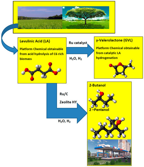
Figure 1.
Conversion of levulinic acid to GVL and levulinic acid to 2-Butanol and 2-Pentanol.
1.1. GVL Production Process Catalysts
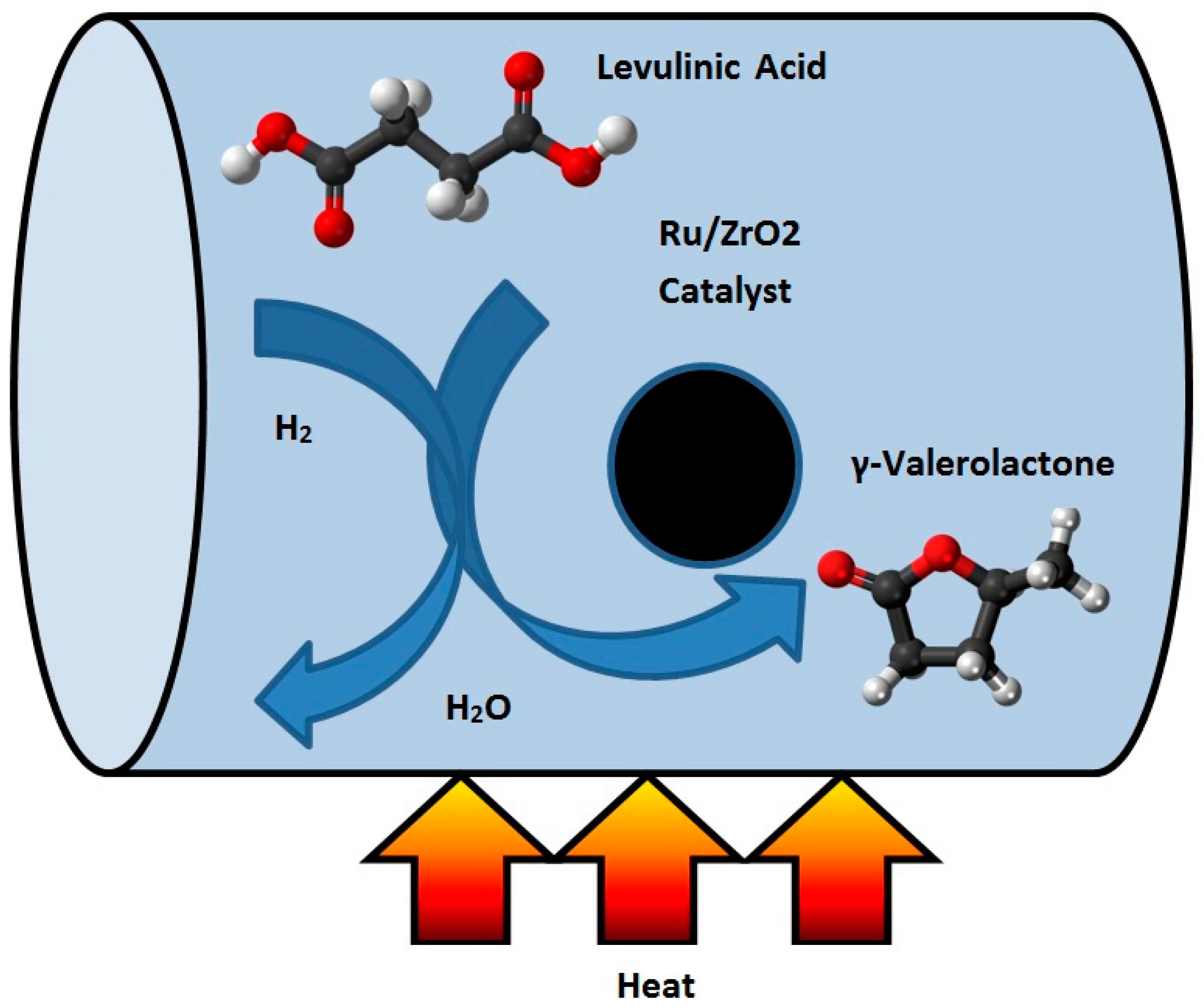
The hydrogenation of LA to GVL has been described by using both homogeneous and heterogeneous catalysts [9]. Filiz et al. [10] studied the catalytic hydrogenation of LA over zirconia supported ruthenium catalysts. They prepared four different Ru/ZrO2 catalysts with different pre-treatments and used different zirconium supports. They discovered that one of the catalysts produced a yield of more than 99% of GVL under mild conditions. This catalyst was also robust and could be recycled at least four times without any loss in activity or selectivity. It was shown that the activity can be attributed to the presence of small ruthenium particles together with acidic sites on the catalyst [10]. Figure 2 shows the schematic of the hydrogenation reactor of LA to GVL.
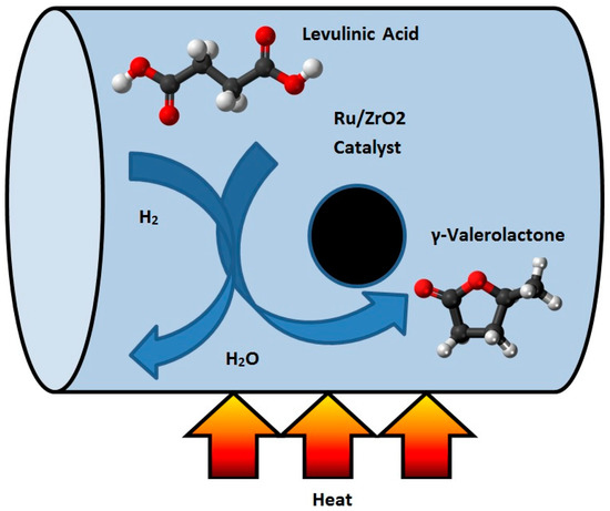
Figure 2.
Schematic of the conversion process of levulinic acid (LA) to γ-valerolactone (GVL).
Ftouni et al. [11] compared the stability of different supported Ru-based catalysts under typical LA hydrogenation conditions in dioxane. It was shown that Ru/ZrO2 performed better than Ru/C and Ru/TiO2. The former catalyst materials displayed high activity, selectivity, and stability upon repetitive recycling. The hydrogenation reaction was studied at the hydrogen pressure of 30 bar and temperature of 423 K in dioxane as the solvent. All catalysts showed excellent yields of GVL when used fresh, but only the Ru/ZrO2 catalyst could maintain these high yields upon multiple recycling. The widely used Ru/TiO2 catalyst already showed quick signs of deactivation after the first catalytic test. The partial deactivation was due to the partial coverage of the Ru nanoparticles. In contrast, the zirconia support displayed high morphological and structural stability even after five recycling tests. In the fresh Ru/ZrO2 catalyst, Ru was found to be fully atomically dispersed on the fresh catalyst even at 1 wt % Ru loading, with some genesis of Ru nanoparticles being observed upon recycling. Further studies with the Ru/ZrO2 catalyst showed that dioxane could be readily replaced by more benign solvents including GVL itself. The addition of water promotes the selective hydrogenation reaction.
1.2. CFD Simulations of Biofuel Production
Wensel et al. [12] performed a computational fluid dynamics (CFD) simulation on the bio-refinery process for succinic acid and co-product. The finite volume method (FVM) technique was employed in the CFD simulation. The simulation included kinetic, stoichiometric, mass, and energy balance equations in order to simulate the effects of inlet temperature impeller speed, diameter, and spacing, inlet temperature, and fermentor volume on the fermentor cooling jacket heat transfer area. Predicted dissolved carbon dioxide concentrations in the fermentor had good agreement with those reported in the literature. The effects of the microfiltration recirculation rate, microfiltration stage numbers, and absorber sorbent particle diameter on the dimensional requirements and power consumption have also been considered. Yields and estimated volume and area requirements for the units of operation were obtained for the baseline process. Their work represents the first reported industrial-scale bio-succinic acid process model. Gorshkova et al. [13] performed a three phase CFD model for trickle bed reactors. Their model was extended to include reactions, mass transfer, and heat transfer. The stationary gas and liquid inside the porous particles were modeled separately from the bulk gas and liquid phases flowing outside the particles with convective and diffusive mass transfer between the inner and outer fluids. It was assumed that the catalytic reactions took place inside the catalyst particles. The process modeled in this work was the hydrogenation of octane (C8H16) in a Ni/Al2O3 reactor. The reaction is highly exothermic, resulting in the evaporation and condensation of the components. All sub models were implemented in Fluent software (version 12.1). Numerical tests were carried out to show that the CFD model allows for the investigation of local variations in the reactor, which are caused, for example, by bed drying or the effects of irregular liquid feed.
The structure of this paper is as follows: The thermodynamic properties of high temperature fluids are described in detail in Section 2.1. Section 2.2 describes the properties and benefits of DOWTHERM A organic fluid. Section 2.3 describes the multiphysics analyses of hydrogenation reactor. Section 3 presents the COMSOL (version 4.3b) results for the temperature and conversion. The described work contains a new design for a hydrogenation reactor for the transformation of levulinic acid to γ-valerolactone (GVL) by using high boiling point organic fluids. This is most likely the first time that organic fluid has been proposed to supply the required heat needed to sustain the hydrogenation reaction for producing GVL.
1.3. Critical Heat Flux of Water
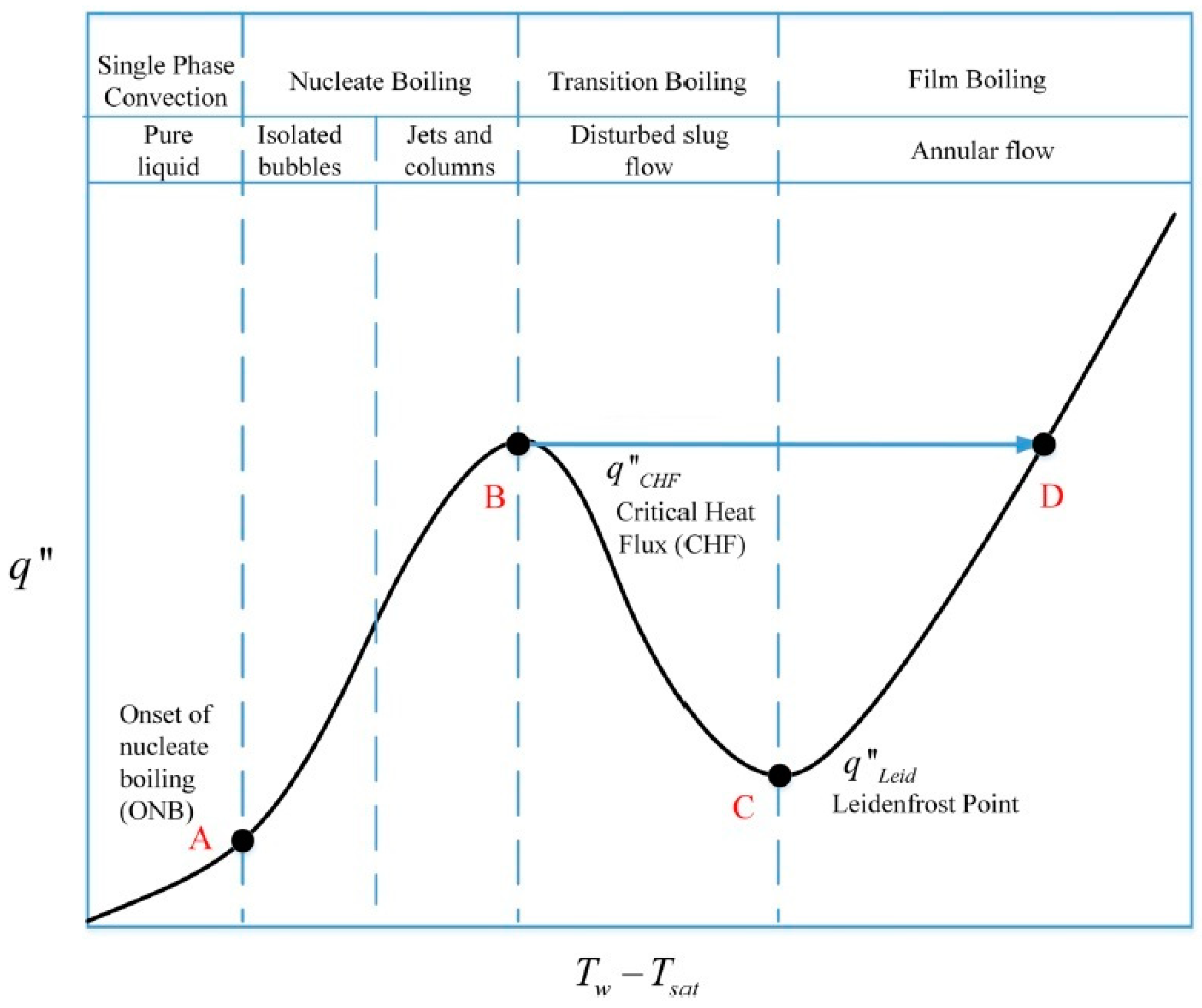
There are inherent benefits of two-phase cooling. A poorly designed two-phase cooling system, however, can fail catastrophically due to critical heat flux. Figure 3 shows the transition from natural convection to nucleate boiling (A), and critical heat flux (B) for water [14,15]. Critical heat flux (B) is marked by an excessive rise in device temperature that can result in the loss of heat transfer to the hydrogenation reactor external surface (D).
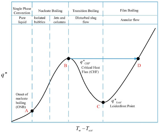
Figure 3.
A typical boiling curve.
At the point of dry-out, the depletion of the liquid layer leads to a significant decrease in heat transfer at the reactor surface, which will result in a decrease of heat flux to the hydrogenation reactor surface. However, apart from the dry-out condition, a similar decrease in heat transfer can also occur at lower vapor qualities during the subcooled or saturated nucleate boiling regimes. This condition is achieved at high heat fluxes when the rapid nucleation of bubbles results in the formation of dry areas that start to cover more and more of the surface. Finally, a vapor film separates the liquid from the reactor surface and film boiling has been initiated. This causes a drastic reduction in heat transfer since the vapor has a much lower thermal conductivity than the liquid. The condition is referred to as the departure from nucleate boiling (DNB) where the point of maximum heat flux is called the critical heat flux (CHF). The organic fluid has inherent benefits over water as its high boiling temperature improves the heat transfer to the hydrogenation reactor surface (the heat flux is more effective at the liquid phase), and has low viscosity (it minimizes the pressure losses).
2. Materials and Methods
2.1. High Temperature Fluids
Table 1 contains a list of heat transfer fluids that boil at temperatures exceeding 100 °C. Most of these fluids are flammable, extremely corrosive, explosive, or harmful (or all four). Three of these fluids may be suitable as a high-temperature coolant such as DOWTHERM (boiling point 258 °C), ethylene glycol (boiling point 197 °C), and propylene glycol (boiling point 187 °C). DOWTHERM A (diphenyl mixture) was developed by the Dow Chemical Company. Propylene glycol and ethylene glycol are organic compounds that are widely used as automotive antifreezes [16].

Table 1.
Boiling points of various fluids at 1 atm [16].
2.2. Properties and Benefits of Utilization of an Organic Fluid
DOWTHERM A (also known as “thermex”) is a mixture composed of biphenyl (C12H10) and diphenyl oxide (C12H10O). These two compounds have practically the same vapor pressures, therefore, this mixture can be considered as a single compound. Diphenyl mixture fluid may be applied in systems employing either liquid phase or vapor phase heating. Its normal application range is 60 °F to 750 °F (15 °C to 400 °C), and its pressure range is from atmospheric to 152.5 psig (10.6 bar) [17]. The diphenyl mixture possesses unsurpassed thermal stability at temperatures of 750 °F (400 °C). The maximum recommended film temperature is 800 °F (425 °C). It has practically no corrosive action on the common structural materials such as steel, cast iron, copper brass, bronze, etc. Even at the high temperatures involved, the equipment usually exhibits excellent service life. Original equipment in many hydraulic systems prolongs after 30 years of continuous service. Stainless steel and low alloy steels, Monel alloys, etc. are also employed in equipment and instruments. This mixture has a freezing point of 53.6 °F (12 °C) and its low viscosity prevents start-up system problems. It is considered as a combustible fluid, however, its vapors do not pose a serious flammability hazard at room temperature, because its saturation concentration is far less than the lower flammability limit [17]. It has a relatively high flash point of 236 °F (113 °C) (SETA), a fire point of 245 °F (118 °C) (C.O.C.), and an auto-ignition temperature of 1110 °F (599 °C) (ASTM, E659-78). The lower flammable limit is 0.6% (volume) at 175 °C, while the upper limit is 6.8% at 190 °C. Ignited diphenyl mixture burns slowly and is practically explosion proof as experience of operating diphenyl heating installations has proven that there is practically no fire hazard from it with proper equipment and operation. Abagnale et al. [18] discussed the usage of DOWTHERM A as a working fluid in the Organic Rankine Cycle (ORC). It has been mentioned in [19] that this fluid has been successfully applied in heat pipes. The use of an organic fluid enables operation near atmospheric pressure and the use of plain carbon steel for the piping system. It was proposed to apply this fluid as coolant for UAV engine [20].
2.3. Multiphysics Analyses of the Hydrogenation Reactor
This section deals with the numerical analysis of the reactor. Figure 4 shows the geometry of the hydrogenation reactor.
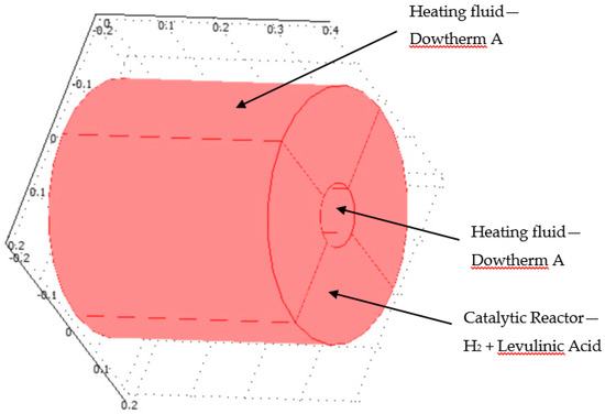
Figure 4.
3D plot of hydrogenation reactor.
The hydrogenation reactor is made of the catalyst bed material. It was assumed that the radius of the reactor was 0.05 m and the height of the reactor was 0.4 m. The hydrogenation chemical reaction occurred inside the catalytic reactor where the heat was supplied through the organic fluid to drive the endothermal reaction system. The heat flux was supplied at the inner and outer radius of the reactor. Levulinc acid and hydrogen were mixed in stoichiometric amounts and entered through the inlet of the hydrogenation reactor. This model investigates the hydrogenation of LA to GVL. COMSOL multi-physics software version 4.3b was applied in this work and simultaneously solved the continuity, Navier-Stokes (fluid flow), energy (heat transfer), and diffusion with chemical reaction kinetics transport equations. The model kinetics are described in detail in Section 2.3.1. Section 2.3.2 describes the continuity and fluid flow. Section 2.3.3 and Section 2.3.4 describe the energy transport and diffusion equations.
2.3.1. Model Kinetics
Inside the hydrogenation reactor, levulinic acid and hydrogen react together to form GVL and water [21]:
Levulinic Acid + H2 → GVL + H2O
The rate constant of the levulinic reaction is temperature dependent according to [21]:
where A represents the frequency factor. It was assumed that its value was 6.2 × 10³ (1/s); E is the activation energy with a value of 48.0 (kJ/mole) [18]; is the gas constant (8.3143 J/(mole·K)); and T represents the temperature (K). It should be noted that this reaction is endothermic (consumes heat). The production rate (mole/(m3·s)) of the GVL is given by:
2.3.2. Fluid Flow and Continuity Equations
Since the hydrogenation reaction occurs at a hydrogen pressure of 30 bar [11], it was assumed that the flow of the hydrogen and levulinic acid inside the hydrogenation reactor was laminar. The flow was incompressible. The flow of species through the bed is described by Navier-Stokes equation [22]:
Since the flow is incompressible, the density of fluid is constant. Thus, the continuity equation for the reacting species is [22]:
where η denotes the dynamic viscosity of the fluid (Pa·s); u the velocity (m/s); ρ the density of the fluid (kg/m3); p the pressure (Pa); and F is a body force term (N/m3).
2.3.3. Energy Transport Equation
The energy balance equation applied to the reactor domain considers heat transfer through convection and conduction [21]:
In Equation (6), cp denotes the specific heat capacity (J/(kg·K)); k is the thermal conductivity of the fluid in (W/(m·K)); and Q is a sink or source term (W/m3). The last term is calculated by the following equation:
where is the heat of reaction in (J/mole). The value of the heat reaction was taken from [23].
2.3.4. Diffusion Transport Equation
The mass transfer in the reactor domain is given by the convection and diffusion equation. The diffusion equation for levulinc acid (LA) is written in Equation (8):
where DLA denotes its diffusion coefficient of LA in the solution in (m2/s) and RLA denotes the reaction term in (mole/(m3·s)). Equation (8) assumes that the species LA is diluted in a solvent. The diffusion equation for the gamma valerolactone (GVL) is written in Equation (9):
where DGVL denotes its diffusion coefficient of GVL in the solution in (m2/s), and RGVL denotes the reaction term in (mole/(m3·s)). The conversion of LA was calculated according to Equation (10).
where denotes the LA concentration at the entrance to the reactor and denotes the LA concentration at the exit of the reactor.
3. Results
This section presents the model results for the temperature and concentration fields. A parametric study was performed to analyze the influence of the input temperature on the hydrogenation reactor performance.
3.1. Model Validation
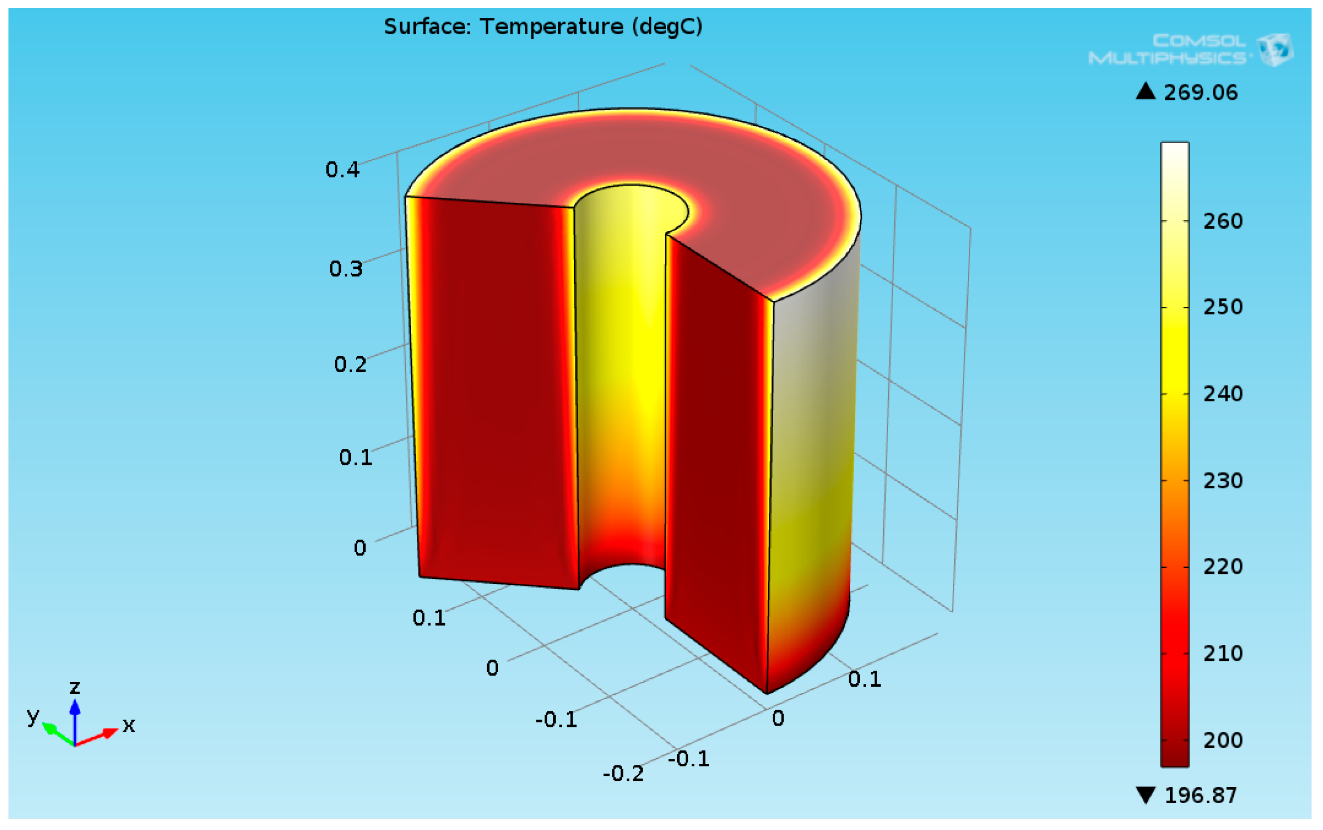
Several works have dealt with burners as a heat source for maintaining the reaction [24,25]. This work focused on the organic fluid heat source. The numerical results for a heat flux of 2730 (W/m²) are presented in this section. It was assumed that the temperature of the reactants entering the hydrogenation reactor was 200 °C. Figure 5 shows the 3D temperature field inside the hydrogenation reactor.
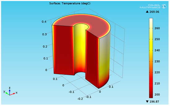
Figure 5.
3D plot of the hydrogenation reactor temperature field.
As seen in Figure 5, the temperature at the bottom section of the reformer is higher than the temperature at the upper side. This is due to two reasons: first, the endothermic reactions absorb the heat, and second, the thermal conductivity of the solution (levulinic acid and hydrogen) has a lower value. The temperature at the internal and external surfaces of the reactor was much higher than the temperature inside the bulk of the reactor, which is because they are exposed to heat supplied by organic fluid. The lower thermal conductivity led to a higher temperature gradient across the radial axis of the reactor. Figure 6 shows the 3D levulinic acid concentration field inside the hydrogenation reactor.
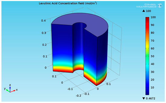
Figure 6.
3D plot of the levulinic acid (LA) concentration field.
Figure 6 indicates that the LA almost converted completely (100% conversion). A similar value has been reported in [26,27,28]. Figure 7 shows the 3D GVL concentration field inside the hydrogenation reactor.

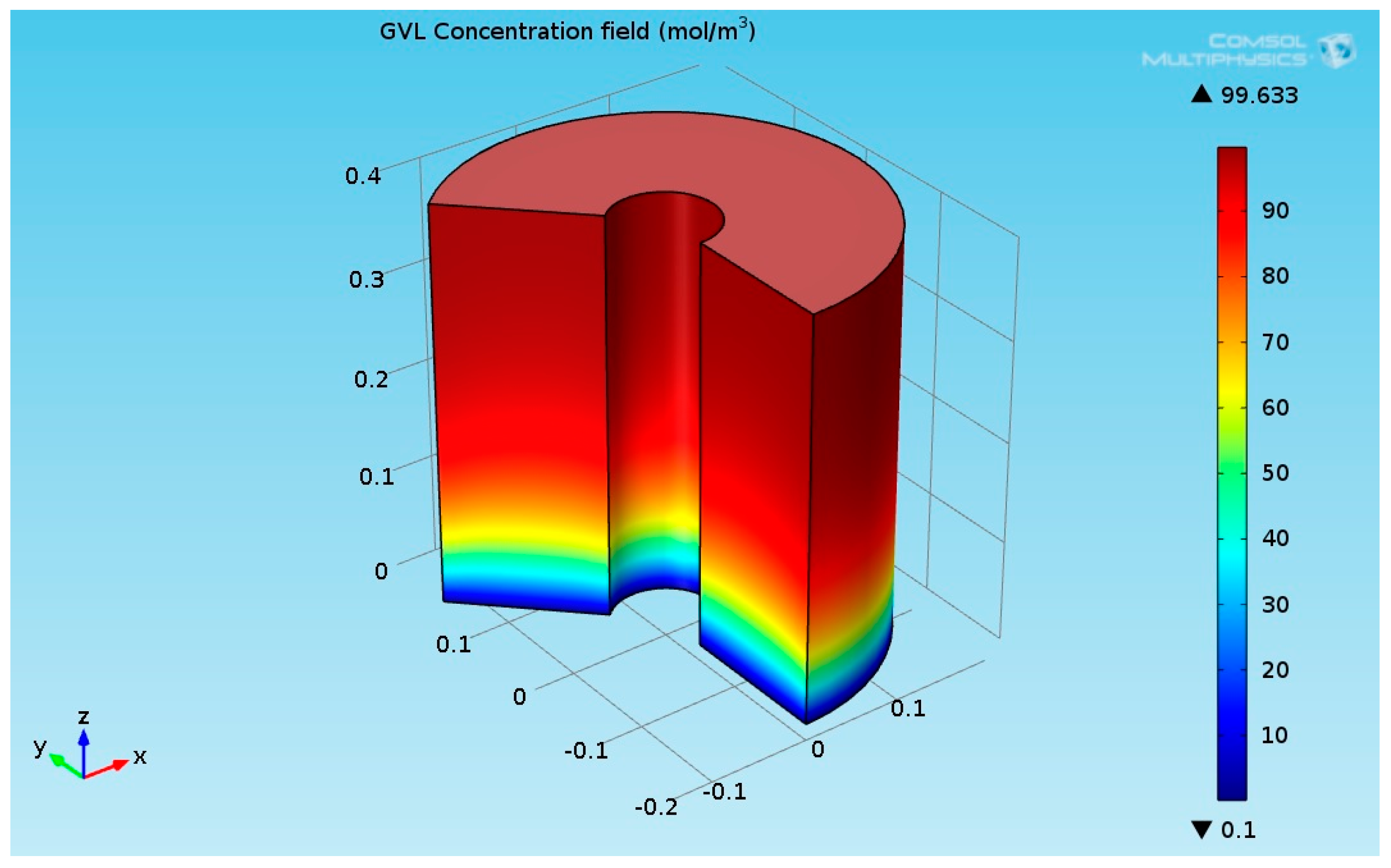
Figure 7.
3D plot of the γ-Valerolactone (GVL) concentration field.
Figure 8 indicates that the LA almost transformed completely to γ-valerolactone (GVL). The concentration of GVL at the top of the hydrogenation reactor had the highest values.

Figure 8.
3D plot of the hydrogenation reactor temperature field.
3.2. Calculated Results for Lower Temperatures
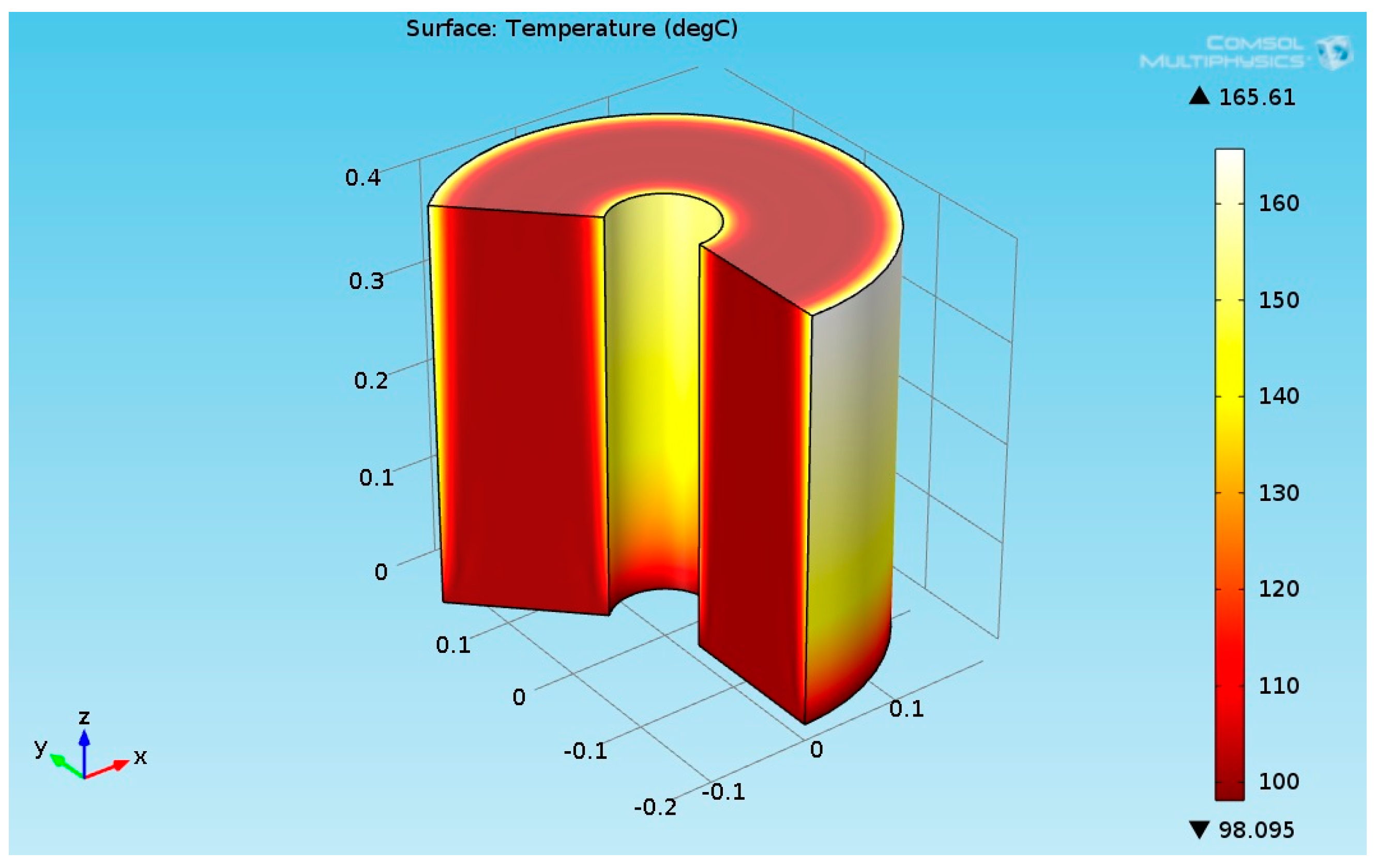
The numerical results for the heat flux input of 2730 (W/m²) are presented in this section. It was assumed that the temperature of the reactants entering to the hydrogenation reactor was 100 °C. Figure 8 shows the 3D temperature field inside the hydrogenation reactor.
As seen from Figure 8, the temperature at the bottom section of the reformer was higher than the temperature at the upper side. This is due to two reasons: first, the endothermic reactions absorb the heat, and second, the thermal conductivity of the solution (levulinic acid and hydrogen) has a lower value. The temperature at the internal and external surfaces of the reactor was much higher than the temperature inside bulk of the reactor because they were exposed to heat supplied by the organic fluid. The lower thermal conductivity led to a higher temperature gradient across the radial axis of the reactor. Figure 9 shows the 3D levulinic acid concentration field inside the hydrogenation reactor.
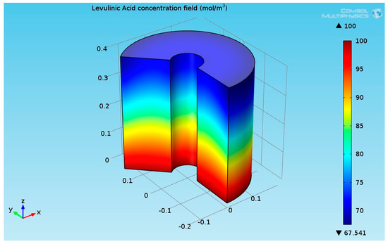
Figure 9.
3D plot of the levulinic acid (LA) concentration field.
Figure 9 indicates that the conversion of LA to GVL was about 32.5%.
4. Discussion
The application of biomass for the production of fuel and chemicals has become an important research topic due to growing concerns about the finite nature of fossil carbon reserves and the environmental impact of our continued dependence on these resources. Levulinic acid (LA) is ranked as one of the “Top 10” building blocks for future bio-refineries as proposed by the US Department of Energy. It is one of the most important platform molecules for the production of fine chemicals and fuels based on its compatibility with existing processes, market economics, and industrial ability to serve as a platform for the synthesis of important derivatives. Hydrogenation of LA to produce γ-valerolactone (GVL) is an active area of research due to the potential of GVL to be used as a biofuel in its subsequent transformation into hydrocarbon fuels. This paper contains a new design for a simple, cost effective, and safe hydrogenation reactor for the transformation of levulinic acid to γ-valerolactone (GVL) by utilizing high boiling point organic fluid. The hydrogenation reactor was composed of the heating source, an organic fluid (called “DOWTHERM A” or “Thermex”) and the catalytic reactor. The advantages of high boiling temperature fluids, along with advances in hydrocracking and reforming technologies driven by the oil and gas industries, make the organic concept even more suitable and safe (water coming in contact with liquid metal can cause steam explosion) for heating the hydrogenation reactor. DOWTHERM A is a mixture composed of biphenyl (C12H10) and diphenyl oxide (C12H10O). These two compounds have practically the same vapor pressures, therefore this mixture can be considered as a single compound. The diphenyl mixture fluid can be applied in systems employing either liquid phase or vapor phase heating. Its normal application range is 60 °F to 750 °F (15 °C to 400 °C), and its pressure range is from atmospheric to 152.5 psig (10.6 bar) [11]. The diphenyl mixture possesses unsurpassed thermal stability at temperatures of 750 °F (400 °C). The maximum recommended film temperature is 800 °F (425 °C) and it has practically no corrosive action on common structural materials such as steel, cast iron, copper brass, bronze, etc. Even at the high temperatures involved, the equipment usually exhibits excellent service life. Original equipment in many hydraulic systems can be prolonged even after 30 years of continuous service. Stainless steel and low alloy steels, Monel alloy, etc. have also been employed in equipment and instruments. This mixture has a freezing point of 53.6 °F (12 °C) and its low viscosity prevents start-up system problems. It is considered as a combustible fluid, however, its vapors do not pose a serious flammability hazard at room temperature because its saturation concentration is far less than the lower flammability limit [11]. It has a relatively high flash point of 236 °F (113 °C) (SETA), a fire point of 245 °F (118 °C) (C.O.C.), and an auto-ignition temperature of 1110 °F (599 °C) (ASTM, E659-78). The lower flammable limit is 0.6% (volume) at 175 °C, while the upper limit is 6.8% at 190 °C. The ignited diphenyl mixture burns slowly and is practically explosion proof as experience of operating diphenyl heating installations has proven that there is practically no fire hazard from it with proper equipment and operation. DOWTHERM A has been considered as a working fluid in the Organic Rankine Cycle (ORC) and has been successfully applied in heat pipes. The usage of organic fluid enables operation near atmospheric pressure and the use of plain carbon steel for the piping system.
COMSOL multi-physics software version 4.3b was applied in this work and simultaneously solves the fluid flow, heat transfer, and diffusion with chemical reaction kinetics equations. This paper presented the model results for the temperature and concentration fields. A parametric study was performed to analyze the influence of the input temperature on performance of the hydrogenation reactor. The numerical results for a heat flux of 2730 (W/m²) were presented in this paper. It was assumed that the temperature of the reactants entering the hydrogenation reactor was 200 °C. The results indicate that the LA almost converted completely (100% conversion) where similar values have been reported in the literature. It was found that the temperature at the bottom section of the reformer was higher than the temperature at the upper side due to two reasons: first, the endothermic reactions absorb the heat, and second, the thermal conductivity of the solution (levulinic acid and hydrogen) has a lower value. The temperature at the internal and external surfaces of the reactor was much higher than the temperature inside the bulk of the reactor because they were exposed to heat supplied by the organic fluid. The lower thermal conductivity led to a higher temperature gradient across the radial axis of the reactor. It was shown that the heat flux supplied by the DOWTHERM A organic fluid could provide the necessary heat flux required for maintaining the hydrogenation process. It was found that the mass fractions of the hydrogen and levulinic acid decreased along the reactor axis and the GVL mass fraction increased along the reactor axis.
5. Conclusions
A new design for a hydrogenation reactor to transform levulinic acid to γ-valerolactone (GVL) by using high boiling point organic fluids is proposed in this section. The heat carried by the DOWTHERM A and supplied to the hydrogenation reactor can be produced by using solar energy or by using other heat sources such as a furnace burner or solar power station. The Hydrogen required for the hydrogenation reaction can be produced by using Methane Steam Reforming System. Figure 10 shows proposed GVL production system.
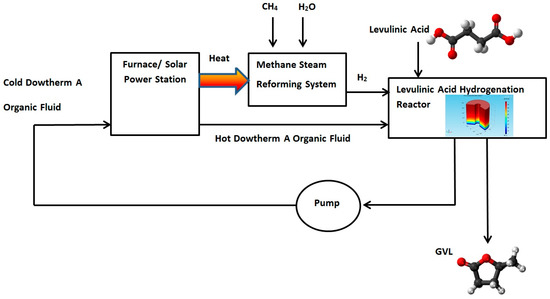
Figure 10.
Proposed γ-Valerolactone (GVL) production system.
Funding
This research received no external funding.
Conflicts of Interest
The author declares no conflict of interest. No funding sponsors had any role in the numerical analyses, or interpretation of data; in the writing of the manuscript, and in the decision to publish the results.
Appendix A. Preliminary Results for Fire Dynamics Simulator of GVL Burner
A computational model for the simulation of GVL burner was developed by using Fire Dynamics Simulator software (FDS) version 5.0 [29,30]. FDS simulation can provide much detailed information on the GVL burner, including the local and transient gas velocity, gas temperature, species concentration, solid wall temperature, fuel burning rate, radiative heat flux, convective heat flux and HRR. The thermomechanical properties of the GVL are listed in Table A1 [7].
Table A1.
Thermomechanical properties of GVL [7].
Table A1.
Thermomechanical properties of GVL [7].
| Material Property | Value |
|---|---|
| Lower Heating value | 25,000 (kJ/kg) |
| density | 1040 (kg/m³) |
The temperature field at t = 42.1 s is shown in Figure A1.

Figure A1.
Temperature field (°C) inside the burner at t = 42.1 s.
Figure A1.
Temperature field (°C) inside the burner at t = 42.1 s.
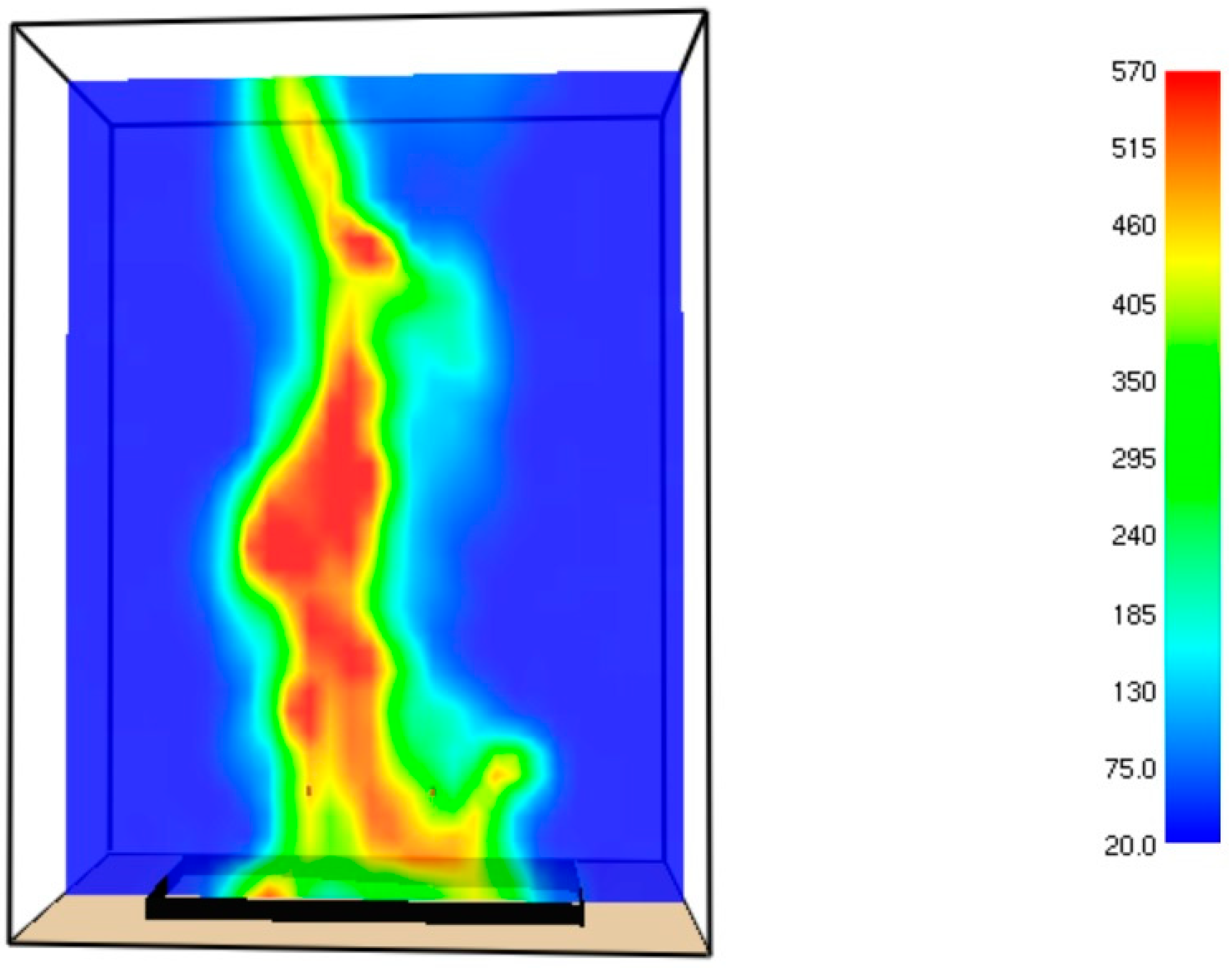
The maximal temperature at time = 42.1 s approaches to 570 °C.
References
- Jones, D.R.; Iqbal, S.; Thomas, L.; Ishikawa, S.; Reece, C.; Miedziak, P.J.; Morgan, D.J.; Bartley, J.K.; Willock, D.J.; Ueda, W.; et al. xNi–yCu–ZrO2 catalysts for the hydrogenation of levulinic acid to gamma valorlactone. Catal. Struct. React. 2018, 4, 12–23. [Google Scholar] [CrossRef]
- Bozell, J.J.; Petersen, G.R. Technology development for the production of biobased products from biorefinery carbohydrates—The US Department of Energy’s “Top 10” revisited. Green Chem. 2010, 12, 539–554. [Google Scholar] [CrossRef]
- Corma, A.; Iborra, S.; Velty, A. Chemical routes for the transformation of biomass into chemicals. Chem Rev. 2007, 107, 2411–2502. [Google Scholar] [CrossRef] [PubMed]
- Paul, S.F. Alternative Fuel. Patent WO1997043356 A1, 16 December 1997. [Google Scholar]
- Horváth, I.T. Gamma-Valerolactone: A Sustainable Liquid for Energy and Carbon Based Chemicals. In Proceedings of the 10th Annual Green Chemistry and Engineering Conference, Washington, DC, USA, 26–30 June 2006. [Google Scholar]
- Horváth, I.T.; Mehdi, H.; Fábos, V.; Boda, L.; Mika, L.T. γ-Valerolactone—A sustainable liquid for energy and carbon-based chemicals. Green Chem. 2008, 10, 238–242. [Google Scholar] [CrossRef]
- Bereczky, Á.; Lukács, K.; Farkas, M.; Dóbé, S. Effect of γ-Valerolactone Blending on Engine Performance, Combustion Characteristics and Exhaust Emissions in a Diesel Engine. Nat. Resour. 2014, 5, 177–191. [Google Scholar]
- Licursi, D.; Antonetti, C.; Fulignati, S.; Giannoni, M.; Raspolli Galletti, A.M. Cascade Strategy for the Tunable Catalytic Valorization of Levulinic Acid and γ-Valerolactone to 2-Methyltetrahydrofuran and Alcohols. Catalysts 2018, 8, 277. [Google Scholar] [CrossRef]
- Chalid, M.; Broekhuis, A.A.; Heeres, H.J. Experimental and kinetic modeling studies on the biphasic hydrogenation of levulinic acid to γ-valerolactone using a homogeneous water-soluble Ru–(TPPTS) catalyst. J. Mol. Catal. A Chem. 2011, 341, 14–21. [Google Scholar] [CrossRef]
- Filiz, B.C.; Gnanakumar, E.S.; Martinez-Arias, A.; Gengler, R.; Rudolf, P.; Rothenberg, G.; Shiju, N.R. Highly Selective Hydrogenation of Levulinic Acid to gamma-Valerolactone Over Ru/ZrO2 Catalysts. Catal. Lett. 2017, 147, 1744–1753. [Google Scholar] [CrossRef]
- Ftouni, J.; Muñoz-Murillo, A.; Goryachev, A.; Hofmann, J.P.; Hensen, E.J.M.; Lu, L.; Kiely, C.J.; Bruijnincx, P.C.A.; Weckhuysen, B.M. ZrO2 Is Preferred over TiO2 as Support for the Ru-Catalyzed Hydrogenation of Levulinic Acid to γ-Valerolactone. ACS Catal. 2016, 6, 5462–5472. [Google Scholar] [CrossRef]
- Wensel, P.; Yu, L.; Chen, S. Simulation with Computational Fluid Dynamics of Succinic Acid and Co-Product Bio-refinery Process. J. Bioprocess. Bio-Tech. 2011. [Google Scholar] [CrossRef]
- Gorshkova, E.; Manninen, M.; Alopaeus, V.; Laavi, H.; Koskinen, J. Three-Phase CFD-Model for Trickle Bed Reactors. Int. J. Nonlinear Sci. Numer. Simul. 2012, 13, 397–404. [Google Scholar] [CrossRef]
- Bergman, T.L.; Incropera, F.P.; DeWitt, D.P.; Lavine, A.S. Fundamentals of Heat and Mass Transfer; John Wiley&Sons: Hoboken, NJ, USA, 2011. [Google Scholar]
- Hu, H.; Xu, C.; Zhao, Y.; Ziegler, K.J.; Chung, J.N. Boiling and quenching heat transfer advancement by nanoscale surface modification. Sci. Rep. 2017, 7, 6117. [Google Scholar] [CrossRef] [PubMed]
- Sharar, D.; Jankowski, N; Bar Cohen, A. Two Phase Fluid Selection for High Temperature Automotive Platforms; ARL-TR-6171; U.S. Army Research Laboratory (ARL): Adelphi, MD, USA, 2012. [Google Scholar]
- Dowtherm, A. Heat Transfer Fluid, Product Technical Tool. Available online: http://www.dow.com/heattrans (accessed on 4 February 2017).
- Abagnale, C.; Cameretti, M.C.; De Robbio, R.; Tuccillo, R. Thermal Cycle and Combustion Analysis of a Solar-Assisted Micro Gas Turbine. Energies 2017, 10, 773. [Google Scholar] [CrossRef]
- Trolove, H.P. Line Focus Solar Stirling Domestic Power Generation. Master’s Thesis, Mechanical Engineering, Department of Mechanical Engineering, University of Canterbury, Canterbury, New Zealand, 1994. [Google Scholar]
- Davidy, A. Proposal of an Alternative UAV Engine Organic Coolants. Preprints 2018, 2018060048. [Google Scholar] [CrossRef]
- Abdelrahman, O.A.; Heyden, A.; Bond, J.Q. Analysis of Kinetics and Reaction Pathways in the Aqueous-Phase Hydrogenation of Levulinic Acid To Form γ-Valerolactone over Ru/C. ACS Catal. 2014, 4, 1171–1181. [Google Scholar] [CrossRef]
- COMSOL Multiphysics—Modeling Guide; Version 4.3b; COMSOL AB: Stockholm, Sweden, 2013.
- Vasiliu, M.; Guynn, K.; Dixon, D.A. Prediction of the Thermodynamic Properties of Key Products and Intermediates from Biomass. J. Phys. Chem. C 2011, 115, 15686–15702. [Google Scholar] [CrossRef]
- Sorrentino, G.; Ceriello, G.; de Joannon, M.; Sabia, P.; Ragucci, R.; Van Oijen, J.; Cavaliere, A.; De Goey, L.P.H. Numerical Investigation of Moderate or Intense Low-Oxygen Dilution Combustion in a Cyclonic Burner Using a Flamelet—Generated Manifold Approach. Energy Fuels 2018, 32, 10242–10255. [Google Scholar] [CrossRef]
- Bao, Z. Performance investigation and optimization of metal hydride reactors for high temperature thermochemical heat storage. Int. J. Hydrogen Energy 2015, 40, 5664–5676. [Google Scholar] [CrossRef]
- Piskun, A.S. Support Screening Studies on the Hydrogenation of Levulinic Acid to γ-Valerolactone in Water Using Ru Catalysts—Chapter 2. In Catalytic Conversion of Levulinic Acid to γ-Valerolactone Using Supported Ru Catalysts: from Molecular to Reactor Level [Groningen]; Rijksuniversiteit: Groningen, The Netherland, 2016. [Google Scholar]
- Koeslag, M. Catalytic Hydrogenation of Levulinic Acid to γ-Valerolactone in a Trickle Bed Reactor, Analysis of Mass Transfer Resistance and Kinetics. Master’s Thesis, University of Groningen, Groningen, Netherlands, 2016. [Google Scholar]
- Piskun, A.; Winkelman, J.G.M.; Tang, Z.; Heeres, H.J. Support Screening Studies on the Hydrogenation of Levulinic Acid to γ-Valerolactone in Water Using Ru Catalysts. Catalysts 2016, 6, 131. [Google Scholar] [CrossRef]
- McGrattan, K. Fire Dynamics Simulator (Version 5)—Technical Reference Guide Volume 1: Mathematical Model; NIST Special Publication 1018; National Institute of Standards and Technology U.S. Department of Commerce: Washington, DC, USA, 2010.
- McGrattan, K.; Forney, G.P. Fire Dynamics Simulator (Version 5)—User’s Guide; NIST Special Publication 1019; National Institute of Standards and Technology U.S. Department of Commerce: Washington, DC, USA, 2010.


© 2019 by the author. Licensee MDPI, Basel, Switzerland. This article is an open access article distributed under the terms and conditions of the Creative Commons Attribution (CC BY) license (http://creativecommons.org/licenses/by/4.0/).