Article

Adsorption Kinetics of CO2 Under Rotation

by
Ramonna I. Kosheleva
,
Agni Moutzouroglou
,
Ioanna Tsolakidi
,
Pigi-Varvara Liouni
,
Eleni Noula
,
Eleni Koumlia
and
Athanasios C. Mitropoulos
*
Hephaestus Laboratory, Department of Chemistry, Faculty of Sciences, Democritus University of Thrace, GR-65404 Kavala, Greece
*
Author to whom correspondence should be addressed.
ChemEngineering 2026, 10(5), 64; https://doi.org/10.3390/chemengineering10050064

Submission received: 18 February 2026 / Revised: 29 April 2026 / Accepted: 6 May 2026 / Published: 13 May 2026

Abstract

The effect of high-gravity fields, generated by rapid rotation, on CO2 adsorption in activated carbon beds is examined. Adsorption-desorption kinetics is monitored before, during, and after short rotation periods at up to 5000 rpm. Rotation induced a reproducible transient bump in headspace pressure, quantitatively attributed to a centrifugal free energy shift (~12.2 J/mol) that overfilled weak adsorption sites beyond their static equilibrium. The bump mechanism is described by fold catastrophe theory, with a critical angular velocity (ωc = 3500 rpm) triggering a sudden transition to a high-occupancy branch. Post-rotation, constant-rate zero-order desorption from shallow sites overlapped with a slower pseudo-first-order adsorption process as deep, previously inaccessible pores became available, increasing CO2 capacity by 2.5%. Kinetic modeling produced an apparent diffusivity of 1.2 × 10⁻⁵ m2/s and a structural accessibility time constant of ~25 h. Thermodynamic analysis showed that rotation improved the overall free energy of adsorption and altered entropy in a manner consistent with the observed adsorption-desorption sequence. These results demonstrate that rotational fields can enhance CO2 uptake, modify kinetic pathways, and trigger threshold phenomena in porous adsorbents.

1. Introduction

The accelerating pace of climate change, driven predominantly by anthropogenic carbon dioxide (CO2) emissions, has prompted an urgent search for scalable, efficient carbon management strategies [1,2,3,4]. Among these, direct air capture (DAC) technologies have emerged as a promising solution for the active removal of CO2 directly from ambient air, thereby addressing emissions that are diffuse or historically accumulated [5]. Direct air capture systems typically operate by passing large volumes of atmospheric air through a material. Once saturated, the material undergoes a regeneration step to release the concentrated CO2 for sequestration or utilization, enabling reuse of the capture medium [6,7]. This process, though conceptually simple, is technologically challenging due to the low concentration of CO2 in air (c.a. 420 ppm), which imposes stringent requirements on the selectivity, capacity, and kinetics of the adsorbent materials used [8,9].
Current DAC technologies primarily fall into two categories [10,11]: solvent-based systems and sorbent-based systems. The first utilize alkaline solutions (e.g., NaOH, KOH) to chemically capture CO2 [12,13]. These systems often require high-temperature regeneration, leading to significant energy demands [14]. The second relies on solid materials [15,16], such as amine-functionalized supports [17], metal-organic frameworks (MOFs) [18], or activated carbons (AC) that capture CO2 via physisorption or chemisorption [19,20], offering potential for lower energy regeneration cycles.
In the case of gas storage in solids, there are certain challenges to be addressed: (a) sufficient adsorption capacity, (b) controllable delivery rates, (c) suitable lifetimes, and (d) recharging characteristics [21,22]. Ongoing research in both industry and academia is firmly centered on overcoming these limitations [21,23,24]. The drive for faster adsorption and controlled desorption kinetics and higher CO2 capacity is at the heart of advancing DAC technology. Faster adsorption-desorption kinetics not only reduce the contact time required per cycle but also allow for smaller equipment footprints and more compact system design: an essential feature for decentralized or modular deployment [25,26,27]. Similarly, increased adsorption capacity can directly translate to higher CO2 capture per unit mass of material, improving the economic and energetic feasibility of the technology.
Activated carbon (AC) is a well-established adsorbent for CO2 capture due to its high surface area, tunable pore size distribution, and chemical stability [28,29]. However, under static conditions, adsorption kinetics can be hindered by pore tortuosity, limited accessibility of internal sites, and slow intraparticle diffusion. These limitations reduce the overall utilization of the adsorbent’s capacity, especially for deep or weakly accessible sites [30].
High-gravity fields generated by rotation offer a unique means to alter this balance by introducing centrifugal forces that enhance radial mass transfer, modify local pressure profiles, and transiently shift adsorption equilibria [31,32,33,34]. Such dynamic perturbations can enable the selective activation of otherwise inaccessible adsorption sites, leading to higher working capacities and potentially novel kinetic pathways [35].
In this work, we have investigated CO2 adsorption kinetics in an AC bed under a rotational field. In particular, we have examined whether or not rotation contributes to greater adsorption capacity, faster kinetics, and controllable delivery rates.

2. Experimental Part

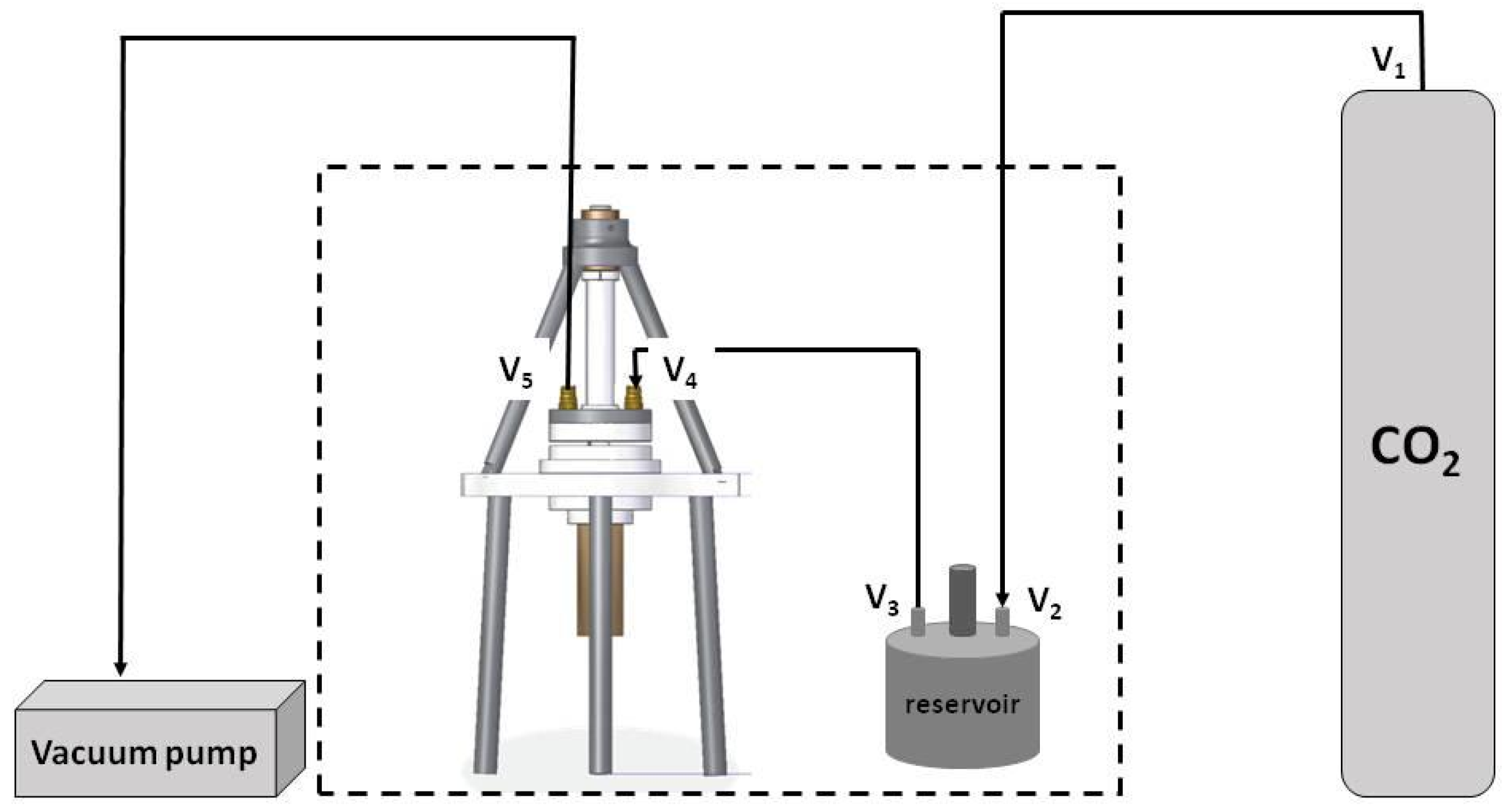
A specially design sample cell that allows adsorption in conjunction with rotation is used in this study (Figure 1). The device consists of a rotating sample chamber of radius rmax = 4.5 cm and height L = 1 mm, a low vibration rotating motor of maximum speed ω = 5000 rpm, a three-digits pressure transducer connected to a rotary slip ring, input/output valves, and an O-ring to secure sealing of the chamber; more details are given elsewhere [36].
A rotary pump is used to achieve vacuum conditions (10−3 mbar), and the isothermal temperature at 20 °C ± 0.1 °C is maintain by air conditioning monitored by a digital thermometer.
Commercially available activated carbon (AC) Norit RX (Cabot Norit Nederland B.V., Amersfoort, The Netherlands), in grains with a size range of 90 μm to 120 μm, is used in this study. The BET area is estimated to be equal to 1110 m2/g, and the average pore size, based on the BJH method, is equal to 16.3 Å. The volume of liquid-N2 that corresponds to the saturation point of the isotherm is taken to be equal to the intra-pore volume Vintra = 0.632 cm3/g. By considering skeletal density of AC ρs = 2 g/cm3 [37,38], the bulk density of the AC grains is ρgr = 0.883 g/cm3. The intra-porosity is then found as the following:
ε int r a = ρ s ρ g r ρ s ρ g × 100 = 56 %
where ρg is the gas density within pores; for empty pores, ρg = 0 g/cm3. Inter-porosity of the rotating bed is calculated from the geometrical volume of the rotating cell, Vcell = 6.36 cm3, and the volume of AC grains of mass 3.6 g that are used to fill the rotating chamber, Vgr = 4.08 cm3:
ε int e r = 1 V g r V c e l l × 100 = 36 % .
The result indicates a random close packing for a rotating packed bed (RPB) with an overall porosity equal to 72%.
Carbon dioxide of high purity (99%) is used for the rotation experiment, which may be divided into three phases: (1) before rotation, (2) during rotation, and (3) after rotation. Preliminary actions such as He-calibration, vacuum outgassing, CO2 input, etc. are conducted before phase 1. In phase 1, pressure drop (ΔP) data are collected per second for 40 h in order to ensure equilibration; the amount of adsorbent is rather large (3.6 g), hence adequate time is needed to reach equilibrium. After that, a rotating run of 60 s is conducted (phase 2), and then ΔP/s data are collected for another 24 h (phase 3). The whole experiment results in 237,000 data points, pressure vs. time, and a similar number of points for possible temperature fluctuations. More details are given elsewhere [39].

3. Results and Discussion

For a gas at pressure P, the Gibbs free energy change ΔG relative to a reference pressure Pref is given as the following [40]:
Δ G = R T ln P P r e f
where R is the gas constant, T is the absolute temperature, and Pref = 1 bar. For adsorption prior to rotation:
Δ G = G f i n a l G s t a r t
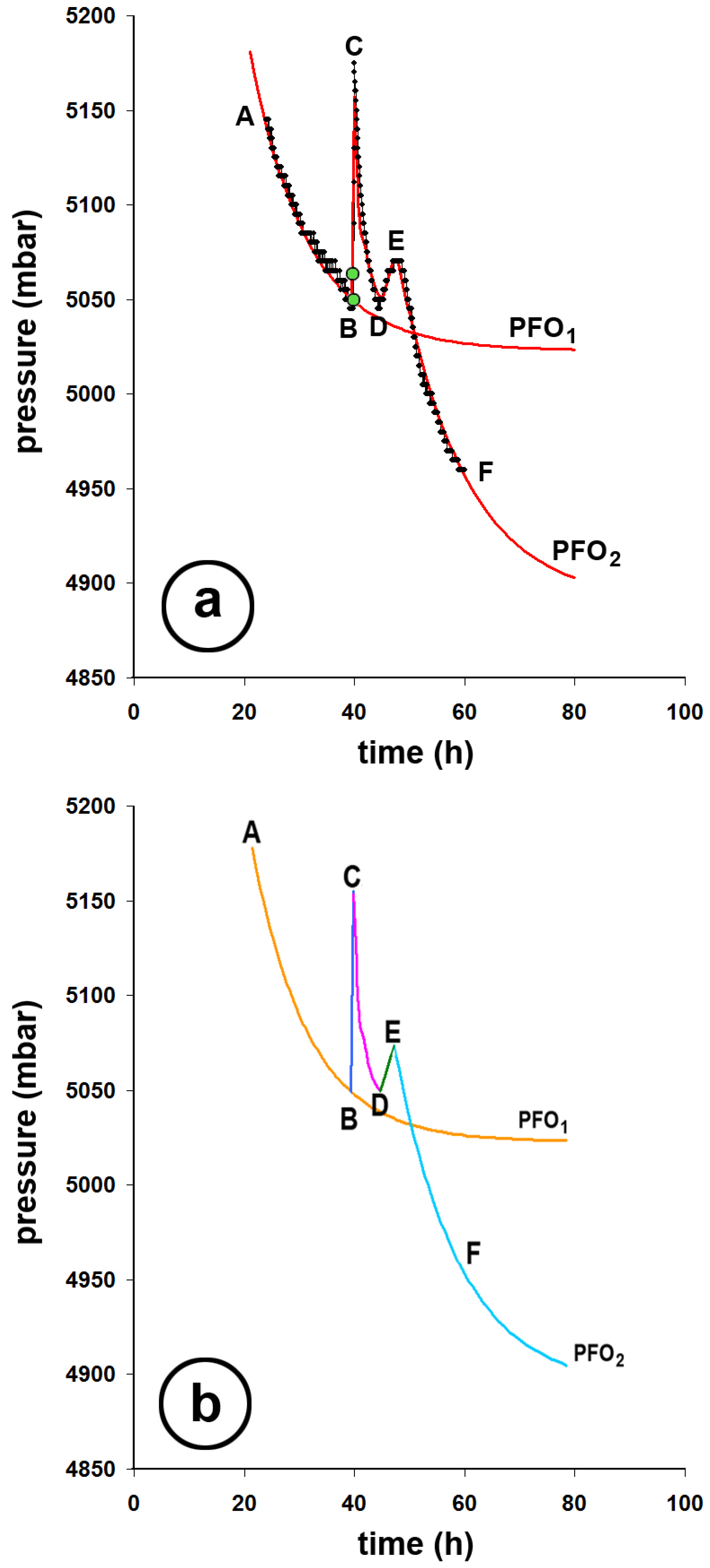
Plugging in initial and equilibrium pressures for each section of Figure 2a, ΔG is obtained. Table 1 summarizes the result.
Figure 2a presents the experimental data fitted to pseudo first order (PFO) kinetics. The process is divided into sections, each of them reflecting adsorption stages such as dynamic adsorption, rotation and its effect, and after rotation impact. More specifically, section AB is from the initial CO2 introduction to the equilibrium reached with no rotation (fitted with PFO1), section BC reflects the instance of rotation, section CD is the time for the system to restore the gas distribution within the cell, DE is a secondary redistribution (from the pores into the bulk), and, lastly, section EF is the final adsorption (fitted with PFO2). Figure 2b presents the modeled results per section of the process. Table 1 shows the results of the thermodynamic analysis of each section. In section AB, the adsorption process is strong with spontaneous uptake; ΔG << 0. In section BC, gas is expelled, due to rotation, from the AC particles (desorption); ΔG > 0. After that (section CD), the system takes a journey back to equilibrium (diffusion) with a partial uptake into AC (re-adsorption ΔG < 0), followed by a small internal redistribution release (section DE, ΔG ≥ 0). At section EF, the system seeks global equilibrium (further adsorption); ΔG < 0. Overall rotation benefits the free energy of the adsorption process by −42.12 J/mol or 8.3%. The Gibbs free energy is calculated from:
Δ G = Δ H T Δ S
where ΔH is the enthalpy change, and ΔS is the entropy change. From adsorption isotherms (reported elsewhere [39]) of CO2 on the given AC, at various temperatures, the isosteric heat of adsorption over a limited pressure range is considered constant ΔHst = ±24,300 J/mol: positive during rotation and negative during adsorption. The last column in Table 1 shows the calculated values for ΔS. In section AB, the entropy decreases due to gas condensation; in BC, it increases due to desorption due to rotation; in CD, there is entropy loss due to re-adsorption; in DE, there is a small entropy gain due to local desorption; and in section EF, the entropy decreases due to further adsorption [41].
We have modeled section AB (Figure 2a) with an equation for PFO kinetics [42]:
P t h = P e q + P 0 P e q exp ( k 1 t )
where Pth is the theoretical pressure to be compared with the experimental one, P0 is the initial pressure, Peq is the equilibrium pressure, k1 is the PFO constant, and t is the time. Fitting parameters are found to be as follows: P0 = 6190 mbar, Peq = 5023 mbar, and k1 = 10.5 h−1. In Figure 2b, the orange line shows this fit.
During rotation, a sudden increase in pressure takes place. In Figure 2a, the two green points indicate where rotation starts and where it stops. However, the pressure kept increasing even after rotation had ceased. Tortuosity τ and porosity ε of the system interplay with the spinning gas [43]:
P ( r ) = P ( 0 ) A ( q ) exp M ω 2 r 2 2 R T × τ ε
where P(r) and P(0) are the pressures at distance r from the rotating axis and at the origin (r = 0), respectively, M is the molecular weight of the gas, and ω is the angular velocity. The factor A(q) takes care for the partial desorption of gas from the porous particles of AC.
A ( q ) = n n o
where no and n are the gas concentrations before and after rotation, respectively. Fitting parameters for Equation (7) are found to be as follows: τ = 2.3, ε = 0.43, and A(q) = 1.007.
For radial diffusion in a porous medium, Fick’s second law is given as follows [44]:
C ( r , t ) t = 1 r r r D e f f C ( r , t ) r
where C(r,t) is the gas concentration in pores, and Deff is the effective diffusivity accounting for τ and ε [45]:
D e f f f = ε D m τ
where Dm is the molecular diffusion in free air. During rotation, higher gas concentration occurs near the outer edge of the cell. We have modified Fick’s second law in order to include a sink term due to adsorption:
C ( r , t ) t + 1 ε ε q ( r , t ) t = 1 r r r D e f f C ( r , t ) r
where q(r,t) is the adsorbed-phase concentration on AC surface. The diffusion/adsorption model presented here is based on several simplifying assumptions. First, radial symmetry is assumed, due to cylindrical geometry of the rotating cell and the uniform distribution of the packed bed. Second, Fickian diffusion is adopted to describe gas transport within the porous medium. Third, the use of an effective diffusivity Deff accounts for the combined effects of porosity and tortuosity, which are independently estimated from the rotating pressure profile (Equation (7)). Furthermore, a linear adsorption isotherm (Henry’s law) is assumed [46]. Finally, the quasi-steady approximation kα→∞ assumes that adsorption equilibrates faster than diffusion. This is consistent with the experimental observation that the initial redistribution (section CD in Figure 2) occurs rapidly compared to the much slower structural relaxation (section EF).
q ( r , t ) t = k a K C ( r , t ) q ( r , t )
where kα is the adsorption rate constant, and K is the adsorption equilibrium constant. For the initial conditions:
C ( r , 0 ) = C ( 0 ) 1 + a r r max 2 and   q ( r , 0 ) = K C ( r , 0 )
where C(0) is the baseline concentration, and α > 0 describes the strength of the non-uniformity due to rotation. Assuming no flux at the center and edge of the cell (closed system), the boundary conditions will be as follows: at r = 0 ∂C/∂r = 0 and at r = rmax ∂C/∂r = 0. Solving Equation (14) for q(r,t) yields the following:
q ( r , t ) = K C ( r , t ) K C ( r , t ) q ( r , 0 ) exp ( k α t )
If the adsorption compared to diffusion is fast kα→∞, then q(r,t)~KC(r,t). This quasi-steady approximation simplifies the coupled Equations (9) and (10) to the following:
1 + 1 ε ε K C ( r , t ) t = D e f f r r r C ( r , t ) r
By defining an effective storage factor φ = [1 + (1 − ε)Κ/ε]:
C ( r , t ) t = D a p p r r r C ( r , t ) r
where Dapp = Deff/φ is the apparent diffusivity reduced by adsorption. A general solution for Equation (18) is as follows:
C ( r , t ) = n = 1 A n J o λ n r r max exp D a p p λ n r max 2 t
where Jo is the Bessel function of the first kind, λn are the roots of J1n) = 0 to satisfy the Neumann (no-flux) boundary condition at r = rmax, and An are coefficients determined from the initial profile.
A n = 2 r max 2 J o 2 ( λ n ) 0 r max r C ( r , 0 ) J o λ n r r max d r = = 2 C ( r , 0 ) λ n 3 J o 2 ( λ n ) 2 a λ n J o ( λ n ) 4 a J 1 ( λ n ) + λ n 2 ( a + 1 ) J 1 ( λ n )
For the data presented in Figure 2a, Equation (20) is further approximated to the following:
P ( r , t ) = P ( 0 ) + A 1 exp ( λ 1 2 D a p p t )
with fitting parameters P(0) = 5045 mbar and A1 = 1.3 × 10¹² mbar, the amplitude of the primary diffusion mode, λ12Dapp = 0.61 h−1, and t in h. The first positive root of J1(λ) = 0 is λ1 = 3.8. Therefore, Dapp = 0.0422 h−1 or 1.2 × 10⁻⁵ m2/s. From Equation (12), it was concluded that τ/ε = 1.36.
We model the bump as a zero-order kinetic, which means that the desorption rate is independent of coverage. This process produces a linear increase in pressure.
P ( t ) = k o R T V h e a d t + P o
where ko is the desorption rate, and Vhead is the headspace volume. From the geometry of the cell and the porosity of the bed, Vhead = 2.7 × 10⁻³ m3, and from the slope dP(t)/dt = 10 mbar/h, ko = 3 × 10⁻⁷ mol/s. The result indicates that the nature of the bump originates from shallow or external surface sites. These sites are saturated after rotation and initial adsorption. Weakly bound CO2 desorbs slowly, not depending on how much is left. These sites behave like a constant-rate gas source for a few hours. After the bump, adsorption kinetics of the PFO are followed. Fitting parameters for Figure 2a and Equation (8) are Po= 5650 mbar, Peq= 4000 mbar, k1 = 0.11 h−1, and C′ = 925 mbar.
From Table 1, it is noted that for section DE, ΔG is equal to the rotation potential for 1 mole of CO2:
Δ μ r o t = 1 2 M ω 2 r 2
That is, Δμrot = 12.2 J/mol. This potential is instantaneous; i.e., it only exists while gas is spinning. In that period, the local equilibrium shifts by the following:
Δ μ r o t = R T ln P r o t P r e s t
Therefore, Prot/Prest~0.49%, and since global pressure Prest~5 bar, rotation adds about 25 mbar to the system, exactly the size of the bump. This potential is the free-energy uphill for CO2 that was left in shallow/external sites after the spin. Rotation prepared a slightly overfilled, metastable population of weak sites. When it stops, the centrifugal term vanishes, but that overfilled population remains. The system then relaxes slowly by zero-order desorption kinetics, and the observable pressure rises by ~25 mbar over ~3 h. This numerical match is not a coincidence. Centrifugal potential populates those weak sites above their resting equilibrium, and the bump reflects releasing that excess.
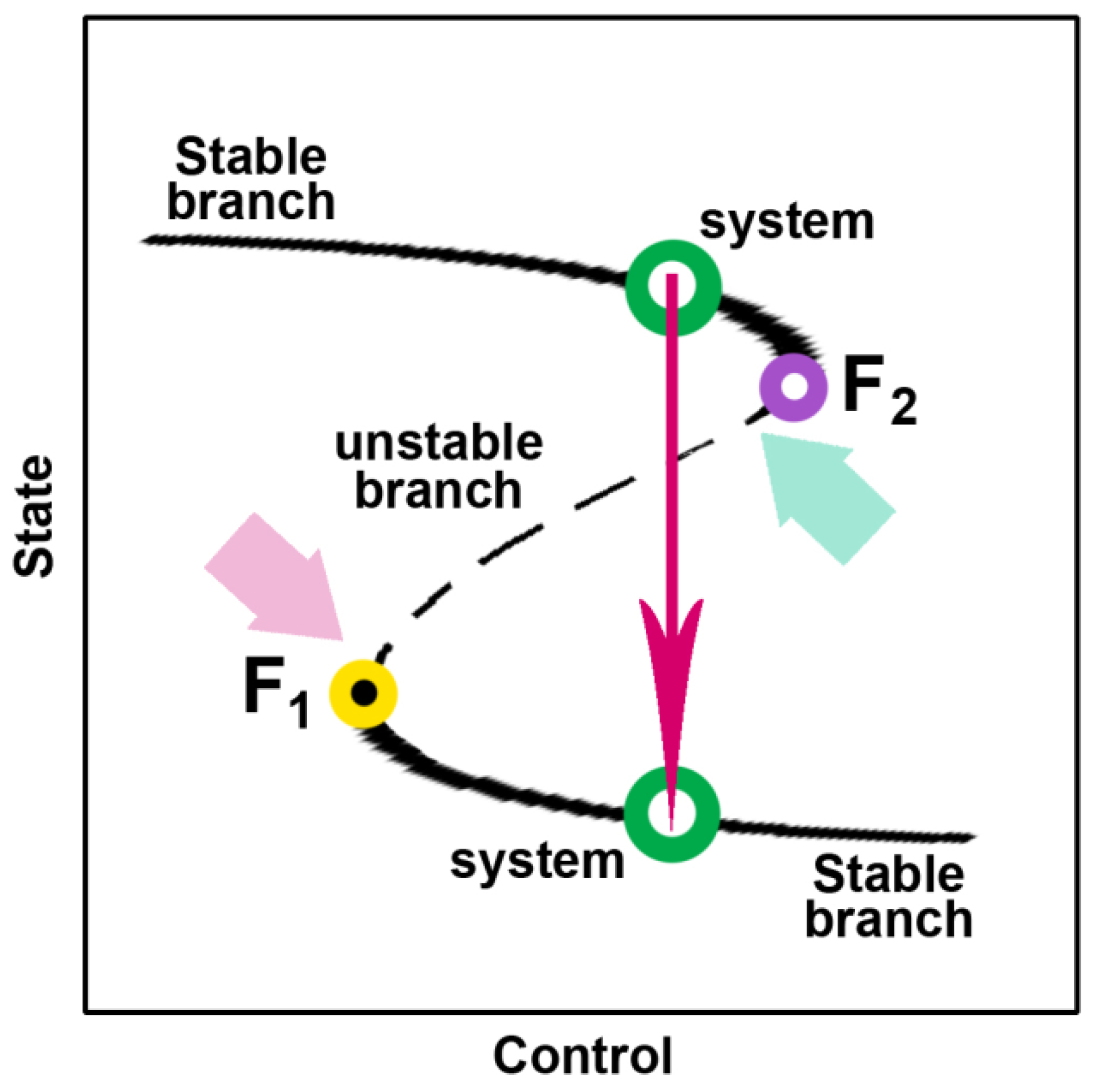
This picture indicates a fold catastrophe type. Figure 3 shows this type. All curves represent stable equilibria, except for the middle one (dashed line). If a system is close to a fold bifurcation point (points F1 or F2), a tiny change can cause a large transition. In the absence of bifurcations, small perturbations can also cause large changes. The adsorption-desorption landscape has two branches: low μ indicates weak sites partly empty, whereas slightly higher μ indicates weak sites more occupied. Rotation shifts μ upward by just enough (12.2 J/mol) to push the system across the fold point into the high-occupancy branch. When rotation stops, μ drops instantly, but the system cannot jump back to the low-occupancy branch instantly because desorption is kinetically limited. Instead, the pressure shows a delayed release, i.e., a bump. This is the hysteresis loop predicted by the fold catastrophe; once the fold point is crossed in one direction, the system returns by a different path.
The catastrophe potential is given as follows:
F ( x , δ ) = x 4 4 δ x 2 2 b x
where x is the coverage of the weak sites, δ is a stiffness parameter, linked to μ and adsorption enthalpy, and b is a bias term from gas-phase pressure. At equilibrium:
d F d x = x 3 δ x b = 0
When δ and b cross certain combinations, the number of real equilibria changes, causing a sudden jump in x.
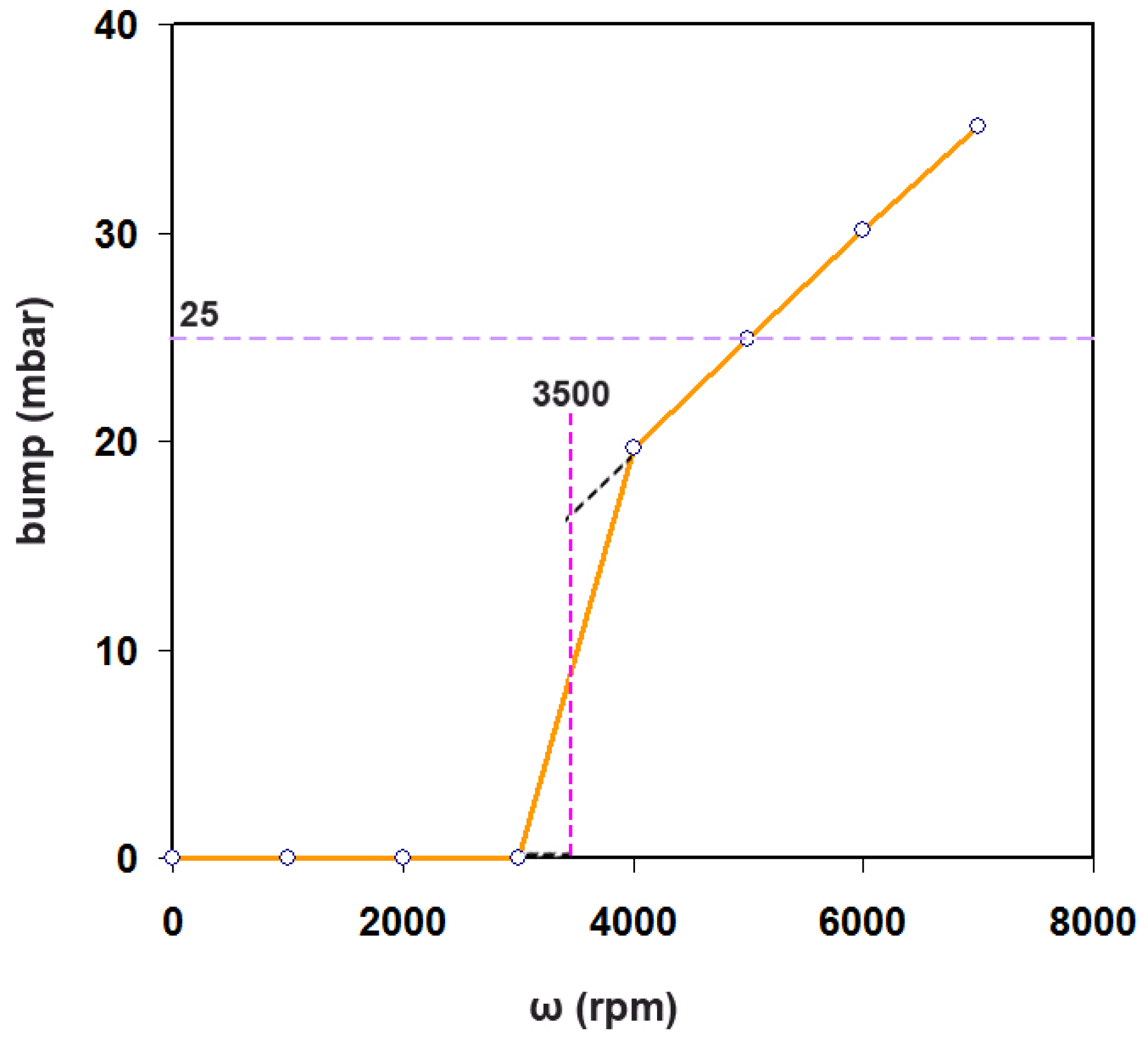
Before rotation parameters δ and b, the system is placed on the lower stable branch. During rotation, μ-shift changes just enough to pass the bifurcation, and the system snaps to a high-occupancy branch. After rotation, μ drops, but diffusion limits how fast it can return; this time lag gives the slow bump before settling. Figure 4 shows this model. At low ω (rpm), no bump appears.
A sharp onset around a critical (threshold) ωc occurs. The observed 25 mbar at 5000 rpm is already on the steep part of the curve; i.e., the system operates close to the fold point. By inspecting the Peq from the two PFO kinetic curves, it is found that for the phase AB, Peq = 5023 mbar, and for phase EF, P′eq = 4900 mbar, while the initial pressure was 6005 mbar. As a result, the total reduction is about 18.4%, while the extra capacity from PFO1 to PFO2 is 2.5%, which corresponds to ~13.5% of the total adsorption.
During rotation, the centrifugal term μ-shift changes by 12.2 J/mol at the rim. Although tiny in absolute energy, it is big enough to change the state of the solid by increasing the fraction of accessible pores. That is, some inaccessible sites deep inside AC particles seem to become accessible. This does not have an immediate pressure effect but appears later. Meanwhile, shallow and external sites that were overfilled during the spin bleed off at a constant rate, hence, the bump. In other words, the bump is announcing that the system operates near catastrophe, into a regime that may accept more CO2. Then the system settles to a new PFO2 branch with lower P′eq [46,47].
d P d t = k a d s P P e q ( θ ) + k 0
where Peq(θ) is the equilibrium headspace pressure, and θ(t) ∈ [0,1] is the accessibility of deep sites (0 = blocked, 1 = fully accessible) [39].
d θ d t = θ ( ω ) θ t θ
where θ(ω) is set by the catastrophe control (centrifugal shift), and tθ is a structural transport relaxation time (slow). A simple monotone mapping from accessibility to equilibrium pressure is as follows:
P e q ( θ ) = P e q Δ P max θ
As θ(t) grows from 0 to 1, the pressure slides from 5023 mbar to 4100 mbar (ΔPmax = 923 mbar). Post-spin with ko > 0 lifts a bump, while θ(t) increases slowly as P(θ) drifts downward. Once kads(P − Peq(θ)) dominates over the small ko, the curve turns to a new PFO2 toward P′eq.
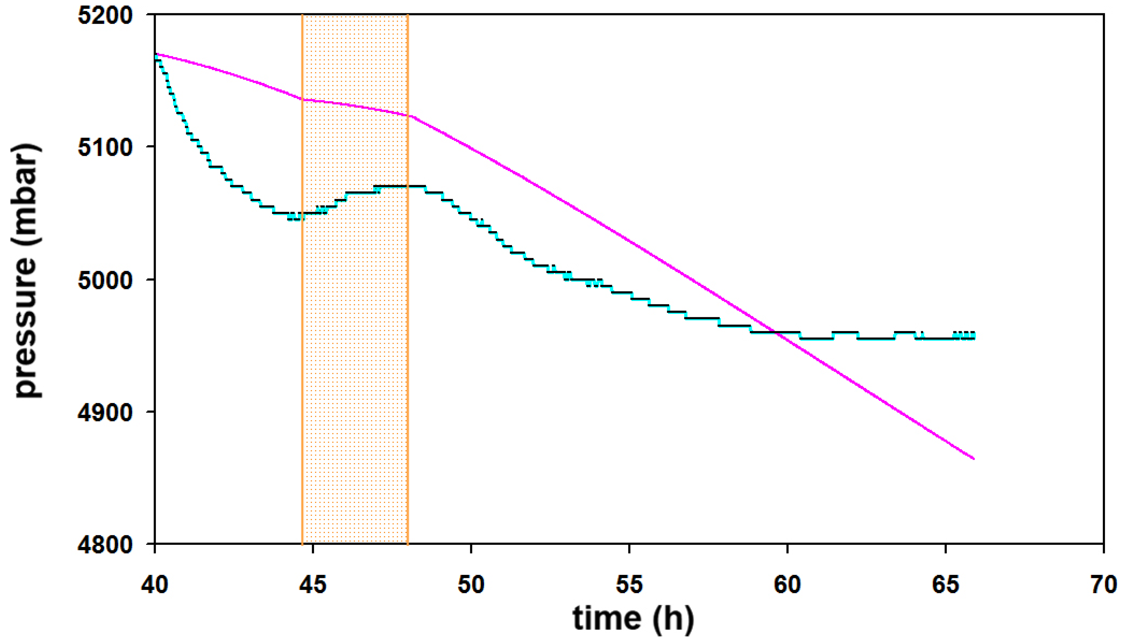
Let the accessibility attractor θ(ω) come from a fold x3 − δ(ω)x − b = 0 where δ(ω) = δoω2, and map the stable-branch solution xst(ω) to θ(ω) = σ(xst(ω)) where σ is a rescaling factor to [0,1]. Threshold behavior (no deep sites below ωc, rapid onset above) drops straight out of the fold. A fit to the data from 40.02–65.9 h is shown as follows:
P ˙ = k a d s P P e q ( θ ( t ) ) + b u m p ( t )
θ ( t ) = 1 exp t t o t θ t t o 0 t < t o
b u m o ( t ) = A t t C o t b u m p t C o   t t C 1 0 o t h e r w i s e
where to = 40.02 h, tCo = 44.68 h, and tC1 = 48.12 h are the onset and the peak in the bump window, and t ≥ to. Figure 5 shows the simulation. Fitted parameters are kads = 0.0351 h−1, tθ = 25.34 h, and ko = 7.22 mbar, with root mean square error over 40.02–65.9 h about 52.2 mbar. The result indicates no immediate pressure effect from the new deep sites captured by θ(t) growing slowly, t(θ)~25 h. A bump is captured by ko = 7.2 mbar/h acting only in the bump window. After the bump, −kads[P − Peq(θ)] dominates. The curve bends down and heads to the lower equilibrium branch, i.e., more CO2 is accepted.

4. Conclusions

While rotating packed beds have been extensively used for process intensification in gas–liquid systems, their application to gas adsorption in porous solids has been limited. In particular, the direct effect of centrifugal fields on adsorption equilibria, site accessibility, and thermodynamic pathways has not been systematically investigated. The present work aims to address this gap. Specifically, this study demonstrates that high-gravity fields generated by rapid rotation can significantly influence CO2 adsorption-desorption dynamics in activated carbon beds. By coupling experimental data with kinetic and thermodynamic modeling, several important findings emerge.
First, rotation induces a measurable and reproducible bump in pressure, which is directly linked to centrifugal effects on gas distribution within the porous structure. This bump is quantitatively explained by a rotational free energy shift of ~12.2 J/mol at the cell rim, sufficient to alter adsorption equilibria. The experimental match between this predicted energy shift and the measured ~25 mbar transient increase strongly supports the proposed mechanism. The bump is interpreted as a fold catastrophe phenomenon: rotation pushes the system across a bifurcation threshold, where weak adsorption sites transition from partially occupied to highly occupied states. When rotation ceases, these sites remain overfilled, releasing gas at a constant rate via zero-order desorption kinetics until equilibrium is re-established.
The sharp onset at a critical angular velocity (ωc = 3500 rpm) confirms the threshold behavior predicted by catastrophe theory. Beyond the transient bump, rotation produces a lasting enhancement in adsorption capacity. Comparison of equilibrium pressures before and after rotation indicates an ~2.5% increase in CO2 uptake, suggesting that centrifugal forces render previously inaccessible deep pores available for adsorption. These newly accessible sites fill slowly (time constant tθ = 25 h), explaining the delayed pressure decay toward a lower post-rotation equilibrium. Kinetic modeling reveals two distinct regimes: a PFO1 adsorption governing initial uptake before rotation and a slow structural accessibility growth controlling post-rotation equilibration, superimposed with the bump’s constant-rate desorption phase (PFO2).
Thermodynamic analysis shows that rotation improves the overall free energy change for adsorption. Entropy variations across experimental phases reflect the interplay between condensation during adsorption, disorder increase during desorption, and partial ordering upon re-adsorption. The effective diffusivity (Dapp = 1.2 × 10⁻⁵ m2/s) calculated from radial diffusion modeling under rotation is consistent with an enhancement in gas transport, likely due to reduced tortuosity and increased accessibility of internal adsorption sites. The observed τ/ε ratio (1.36) indicates a moderate restriction in diffusion compared to free molecular motion, which rotation partially alleviates.
Overall, this work establishes that high-gravity operation can do the following: (a) activate weakly bound and deep adsorption sites, increasing total CO2 capacity; (b) induce threshold phenomena consistent with fold catastrophe theory, enabling abrupt state changes in adsorption behavior; (c) enhance mass transfer through reduced tortuosity and modified local pressure gradients; and (d) allow controllable desorption profiles, potentially valuable for tuned gas delivery applications. These findings open a pathway toward rotationally enhanced DAC designs where centrifugal fields are deliberately exploited to surpass static adsorption limits. The combined mechanistic insight linking centrifugal thermodynamics, catastrophe theory, and adsorption kinetics provides a framework for optimizing such systems.
Although rotational operation introduces additional energy input, it offers unique advantages, including enhanced mass transfer, activation of otherwise inaccessible adsorption sites, and the possibility of controlled desorption without thermal input. These effects could reduce regeneration energy requirements in future optimized systems. Future work should investigate scale-up potential, energy cost-benefit analysis of rotation, and the applicability of these effects to other sorbents, especially those with hierarchical pore architectures or tailored surface chemistries.

Author Contributions

Conceptualization, R.I.K. and A.C.M.; methodology, R.I.K. and A.M.; validation, R.I.K., A.M., I.T., P.-V.L., E.N. and E.K.; formal analysis, R.I.K. and A.M.; investigation, R.I.K., I.T., P.-V.L., E.N. and E.K.; data curation, R.I.K.; writing—original draft preparation, R.I.K., A.M., I.T., P.-V.L., E.N. and E.K.; writing—review and editing, R.I.K. and A.C.M.; visualization, I.T., P.-V.L., E.N. and E.K.; supervision, A.C.M. All authors have read and agreed to the published version of the manuscript.

Funding

This research received no external funding.

Data Availability Statement

The original contributions presented in this study are included in the article. Further inquiries can be directed to the corresponding author.

Conflicts of Interest

The authors declare no conflicts of interest.

References

  1. Sodiq, A.; Abdullatif, Y.; Aissa, B.; Ostovar, A.; Nassar, N.; El-Naas, M.; Amhamed, A. A review on progress made in direct air capture of CO2. Environ. Technol. Innov. 2023, 29, 102991. [Google Scholar] [CrossRef]
  2. Fasihi, M.; Efimova, O.; Breyer, C. Techno-economic assessment of CO2 direct air capture plants. J. Clean. Prod. 2019, 224, 957–980. [Google Scholar] [CrossRef]
  3. Breyer, C.; Fasihi, M.; Bajamundi, C.; Creutzig, F. Direct Air Capture of CO2: A Key Technology for Ambitious Climate Change Mitigation. Joule 2019, 3, 2053–2057. [Google Scholar] [CrossRef]
  4. Keith, D.W.; Holmes, G.; St Angelo, D.; Heidel, K. A Process for Capturing CO2 from the Atmosphere. Joule 2018, 2, 1573–1594. [Google Scholar] [CrossRef]
  5. Zhu, X.; Xie, W.; Wu, J.; Miao, Y.; Xiang, C.; Chen, C.; Ge, B.; Gan, Z.; Yang, F.; Zhang, M.; et al. Recent advances in direct air capture by adsorption. Chem. Soc. Rev. 2022, 51, 6574–6651. [Google Scholar] [CrossRef]
  6. Jiang, L.; Liu, W.; Wang, R.; Gonzalez-Diaz, A.; Rojas-Michaga, M.; Michailos, S.; Pourkashanian, M.; Zhang, X.; Font-Palma, C. Sorption direct air capture with CO2 utilization. Prog. Energy Combust. Sci. 2023, 95, 101069. [Google Scholar] [CrossRef]
  7. Wei, Y.-M.; Peng, S.; Kang, J.-N.; Liu, L.-C.; Zhang, Y.; Yang, B.; Yu, B.-Y.; Liao, H. Unlocking the economic potential of Direct Air Capture technology: Insights from a component-based learning curve. Technol. Forecast. Soc. Change 2025, 215, 124109. [Google Scholar] [CrossRef]
  8. Darunte, L.A.; Walton, K.S.; Sholl, D.S.; Jones, C.W. CO2 capture via adsorption in amine-functionalized sorbents. Curr. Opin. Chem. Eng. 2016, 12, 82–90. [Google Scholar] [CrossRef]
  9. Navik, R.; Wang, E.; Ding, X.; Yunyi, H.; Liu, Y.; Li, J. Enhanced post-combustion CO2 capture and direct air capture by plasma surface functionalization of graphene adsorbent. J. Energy Chem. 2025, 100, 653–664. [Google Scholar] [CrossRef]
  10. Zhao, Y.; Zheng, B.; Zhang, J.; Xu, H. Research on Direct Air Capture: A Review. Energies 2025, 18, 6632. [Google Scholar] [CrossRef]
  11. McQueen, N.; Gomes, K.; McCormick, C.; Blumanthal, K.; Pisciotta, M.; Wilcox, J. A review of direct air capture (DAC): Scaling up commercial technologies and innovating for the future. Prog. Energy 2021, 3, 32001. [Google Scholar] [CrossRef]
  12. Dhoke, C.; Zaabout, A.; Cloete, S.; Amini, S. Review on Reactor Configurations for Adsorption-Based CO2 Capture. Ind. Eng. Chem. Res. 2021, 60, 3779–3798. [Google Scholar] [CrossRef]
  13. Liu, L.; Gong, F.; Xiao, R. Direct Air Carbon Capture and Recovery Utilizing Alkaline Solution Circulation. Energy Fuels 2023, 37, 9339–9346. [Google Scholar] [CrossRef]
  14. Ghadyanlou, F.; Azari, A.; Vatani, A. Experimental Investigation of Mass Transfer Intensification for CO2 Capture by Environment-Friendly Water Based Nanofluid Solvents in a Rotating Packed Bed. Sustainability 2022, 14, 6559. [Google Scholar] [CrossRef]
  15. Wiegner, J.F.; Grimm, A.; Weimann, L.; Gazzani, M. Optimal Design and Operation of Solid Sorbent Direct Air Capture Processes at Varying Ambient Conditions. Ind. Eng. Chem. Res. 2022, 61, 12649–12667. [Google Scholar] [CrossRef]
  16. Mennitto, R.; Blom, R.; Dörr, M.; Rosental, M.; Rettenmaier, N. Solid sorbents for direct air capture: A technological and environmental perspective. Curr. Opin. Chem. Eng. 2025, 50, 101195. [Google Scholar] [CrossRef]
  17. Davis, M.C.; Kort-Kamp, W.J.M.; Matanovic, I.; Zelenay, P.; Holby, E.F. Design of active sites for amine-functionalized direct air capture materials using integrated high-throughput calculations and machine learning. Commun. Chem. 2025, 9, 12. [Google Scholar] [CrossRef]
  18. Zhang, X.; Zhao, H.; Yang, Q.; Yao, M.; Wu, Y.; Gu, Y. Direct air capture of CO2 in designed metal-organic frameworks at lab and pilot scale. Carbon Capture Sci. Technol. 2023, 9, 100145. [Google Scholar] [CrossRef]
  19. Zhang, C.; Sun, S.; He, S.; Wu, C. Direct air capture of CO2 by KOH-activated bamboo biochar. J. Energy Inst. 2022, 105, 399–405. [Google Scholar] [CrossRef]
  20. Hashmi, S.A.M.; Rasool, M.H.; Husain, W.; Moiz, H. Activated Carbons for Direct Air Capture: Adsorption Mechanisms, Material Design and Performance Optimization. J. Petro. Chem. Eng. 2025, 3, 80–88. [Google Scholar]
  21. Acevedo, S.; Giraldo, L.; Moreno-Piraján, J.C. Adsorption of CO2 on Activated Carbons Prepared by Chemical Activation with Cupric Nitrate. ACS Omega 2020, 5, 10423–10432. [Google Scholar] [CrossRef]
  22. Mohamed Hatta, N.S.; Aroua, M.K.; Hussin, F.; Gew, L.T. A Systematic Review of Amino Acid-Based Adsorbents for CO2 Capture. Energies 2022, 15, 3753. [Google Scholar] [CrossRef]
  23. Barker-Rothschild, D.; Chen, J.; Wan, Z.; Renneckar, S.; Burgert, I.; Ding, Y.; Lu, Y.; Rojas, O.J. Lignin-based porous carbon adsorbents for CO2 capture. Chem. Soc. Rev. 2025, 54, 623–652. [Google Scholar] [CrossRef] [PubMed]
  24. Holmes, H.E.; Banerjee, S.; Vallace, A.; Lively, R.P.; Jones, C.W.; Realff, M.J. Tuning sorbent properties to reduce the cost of direct air capture. Energy Environ. Sci. 2024, 17, 4544–4559. [Google Scholar] [CrossRef]
  25. Khan, S.A.; Ahmed, S.; Ali, S.; Altaf, F. Advances in CO2 Capture Materials: From Strategies to CO2-Based Fertilizers for a Sustainable Future. Carbon Neutraliz. 2025, 4, e70063. [Google Scholar] [CrossRef]
  26. Hadi, A.I.; Yan, A.; Hu, Y.; Lin, B.; Zhou, T.; Ouyang, D.; Tang, J. A comprehensive review of carbon capture: From conventional to emerging electrochemical technologies. Next Energy 2025, 9, 100415. [Google Scholar] [CrossRef]
  27. Zanatta, M. Materials for Direct Air Capture and Integrated CO2 Conversion: Advancement, Challenges, and Prospects. ACS Mater. Au 2023, 3, 576–583. [Google Scholar] [CrossRef]
  28. Ahmed, M.B.; Johir, A.H.; Zhou, J.L.; Ngo, H.H.; Nghiem, L.D.; Richardson, C.; Moni, M.A.; Bryant, M.R. Activated carbon preparation from biomass feedstock: Clean production and carbon dioxide adsorption. J. Clean. Prod. 2019, 225, 405–413. [Google Scholar] [CrossRef]
  29. Jedli, H.; Almonnef, M.; Rabhi, R.; Mbarek, M.; Abdessalem, J.; Slimi, K. Activated Carbon as an Adsorbent for CO2 Capture: Adsorption, Kinetics, and RSM Modeling. ACS Omega 2024, 9, 2080–2087. [Google Scholar] [CrossRef] [PubMed]
  30. Rashidi, N.A.; Yusup, S. An overview of activated carbons utilization for the post-combustion carbon dioxide capture. J. CO2 Util. 2016, 13, 1–16. [Google Scholar] [CrossRef]
  31. Jiao, W.; Luo, S.; He, Z.; Liu, Y. Applications of high gravity technologies for wastewater treatment: A review. Chem. Eng. J. 2017, 313, 912–927. [Google Scholar] [CrossRef]
  32. Neumann, K.; Gladyszewski, K.; Groß, K.; Qammar, H.; Wenzel, D.; Górak, A.; Skiborowski, M. A guide on the industrial application of rotating packed beds. Chem. Eng. Res. Des. 2018, 134, 443–462. [Google Scholar] [CrossRef]
  33. Singh, M.P.; Alatyar, A.M.; Berrouk, A.S.; Saeed, M. Numerical modelling of rotating packed beds used for CO2 capture processes: A review. Can. J. Chem. Eng. 2023, 101, 6170–6202. [Google Scholar] [CrossRef]
  34. Rao, D.P.; Bhowal, A.; Goswami, P.S. Process Intensification in Rotating Packed Beds (HIGEE):  An Appraisal. Ind. Eng. Chem. Res. 2004, 43, 1150–1162. [Google Scholar] [CrossRef]
  35. Mitropoulos, A.C.; Kosheleva, R.I.; Kostoglou, M.; Karapantsios, T.D. The Effect of Rotation on Gas Storage in Nanoporous Materials. Separations 2024, 11, 72. [Google Scholar] [CrossRef]
  36. Kosheleva, R.I.; Karapantsios, T.D.; Kostoglou, M.; Mitropoulos, A.C. A novel device for in situ study of gas adsorption under rotation. Rev. Sci. Instrum. 2021, 92, 45106. [Google Scholar] [CrossRef]
  37. Bulbul, S.; Ergün, M. Production and characterization of activated carbon from Black Poplar (Populus Nigra) wood waste with different chemical activation methods. Int. Adv. Res. Eng. J. 2022, 6, 167–175. [Google Scholar] [CrossRef]
  38. Bonaventura, C.P.; Bartucci, S.; Conte, G.; Desiderio, G.; Agostino, R.G.; Policicchio, A. Optimizing CO2 and CH4 storage: The role of high skeletal density activated carbon in adsorption processes. Colloids Surf. A Physicochem. Eng. Asp. 2025, 721, 137209. [Google Scholar] [CrossRef]
  39. Kosheleva, R.I.; Karapantsios, T.D.; Kostoglou, M.; Mitropoulos, A.C. Thermodynamic analysis of the effect of rotation on gas adsorption. J. Non-Equilib. Thermodyn. 2023, 48, 403–416. [Google Scholar] [CrossRef]
  40. Choudhary, V.R.; Mayadevi, S. Adsorption of methane, ethane, ethylene, and carbon dioxide on silicalite-l. Zeolites 1996, 17, 501–507. [Google Scholar] [CrossRef]
  41. Singh, V.K.; Kumar, E.A. Experimental investigation and thermodynamic analysis of CO2 adsorption on activated carbons for cooling system. J. CO2 Util. 2017, 17, 290–304. [Google Scholar] [CrossRef]
  42. Tan, K.L.; Hameed, B.H. Insight into the adsorption kinetics models for the removal of contaminants from aqueous solutions. J. Taiwan Inst. Chem. Eng. 2017, 74, 25–48. [Google Scholar] [CrossRef]
  43. Geyko, V.I.; Fisch, N.J. Reduced Compressibility and an Inverse Problem for a Spinning Gas. Phys. Rev. Lett. 2013, 110, 150604. [Google Scholar] [CrossRef] [PubMed]
  44. Shi, S. Diffusion model based on Fick’s second law for the moisture absorption process in wood fiber-based composites: Is it suitable or not? Wood Sci. Technol. 2007, 41, 645–658. [Google Scholar] [CrossRef]
  45. Kim, Y.; Gostick, J.T. Measuring effective diffusivity in porous media with a gasket-free, radial arrangement. Int. J. Heat Mass Transf. 2019, 129, 1023–1030. [Google Scholar] [CrossRef]
  46. Revellame, E.D.; Fortela, D.L.; Sharp, W.; Hernandez, R.; Zappi, M.E. Adsorption kinetic modeling using pseudo-first order and pseudo-second order rate laws: A review. Clean. Eng. Technol. 2020, 1, 100032. [Google Scholar] [CrossRef]
  47. Ho, Y.S.; McKay, G. Pseudo-second order model for sorption processes. Process Biochem. 1999, 34, 451–465. [Google Scholar] [CrossRef]
Figure 1. Schematic representation of the experimental setup; the detail description is given in [36].
Chemengineering 10 00064 g001
Figure 2. Adsorption kinetics of CO2 on activated carbon: (a) The experimental data (black dots) and the fit lines (red) to different sections of the curve; green dots indicate where rotation started and where it ended. (b) The fit lines for each section: orange PFO1 before rotation, blue during rotation, magenta after rotation, green desorption, and cyan the PFO2 extra adsorption.
Chemengineering 10 00064 g002
Figure 3. Fold catastrophe: the black lines represent stable paths, the broken one an unstable path; F1 and F2 are points where the system jumps from one stable to another stable path. Unstable region is depicted with the dashed curve.
Chemengineering 10 00064 g003
Figure 4. Fold catastrophe for the bump: orange line shows the model. The critical angular velocity is ωc = 3500 rpm. The size of the bump is 25 mbar in the steep part of the model curve.
Chemengineering 10 00064 g004
Figure 5. Simulation of the bump (cyan/black point) based on attractor from fold catastrophe (magenta line). The orange hatched section shows the fit.
Chemengineering 10 00064 g005
Table 1. Free energy of sections.
SectionTransition
(mbar)
ΔG
(J/mol)
ΔS
(J/mol.K)
AB6190 to 5045−507.01−79.80
BC5045 to 5175+63.07+81.29
CD5175 to 5045−63.07−81.29
DE5045 to 5070+12.25+81.46
EF5070 to 4960−54.37−81.32
Disclaimer/Publisher’s Note: The statements, opinions and data contained in all publications are solely those of the individual author(s) and contributor(s) and not of MDPI and/or the editor(s). MDPI and/or the editor(s) disclaim responsibility for any injury to people or property resulting from any ideas, methods, instructions or products referred to in the content.