3.1. Logistic Network & Resources
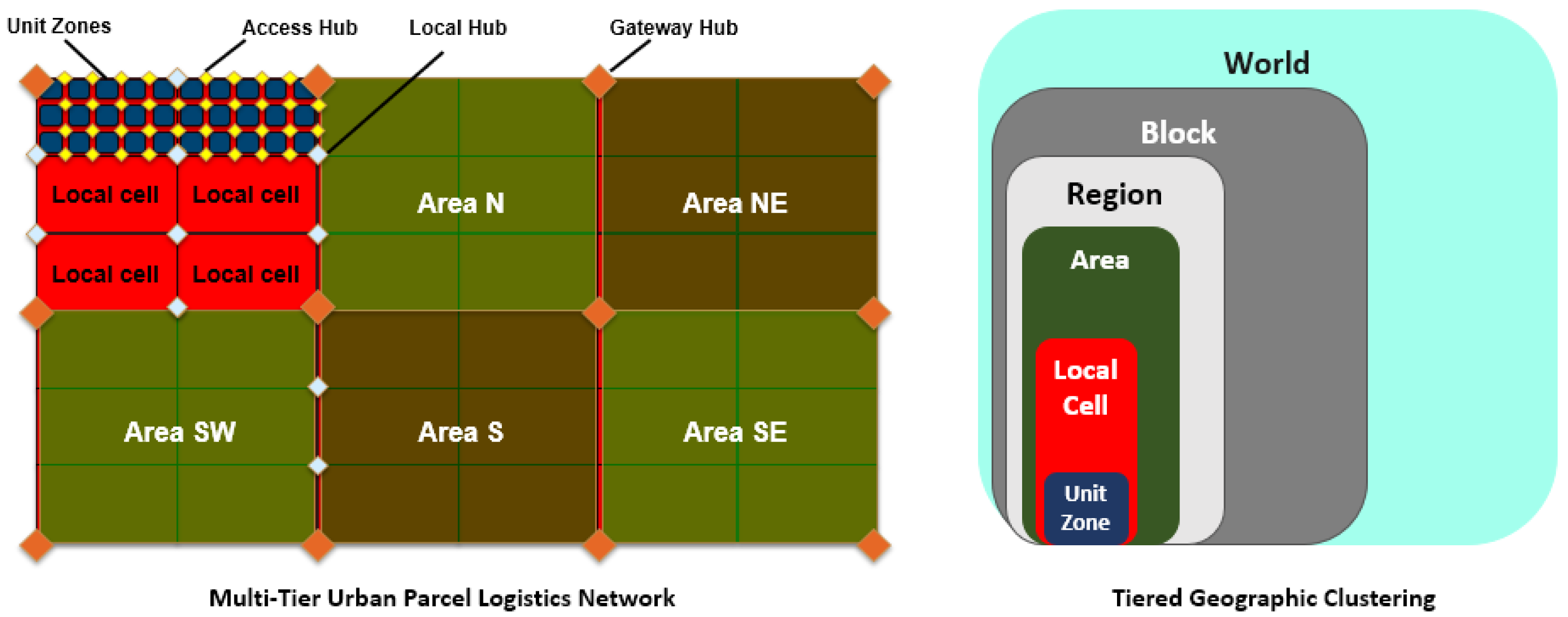
In the Multi-tier Urban Parcel Logistic Web (
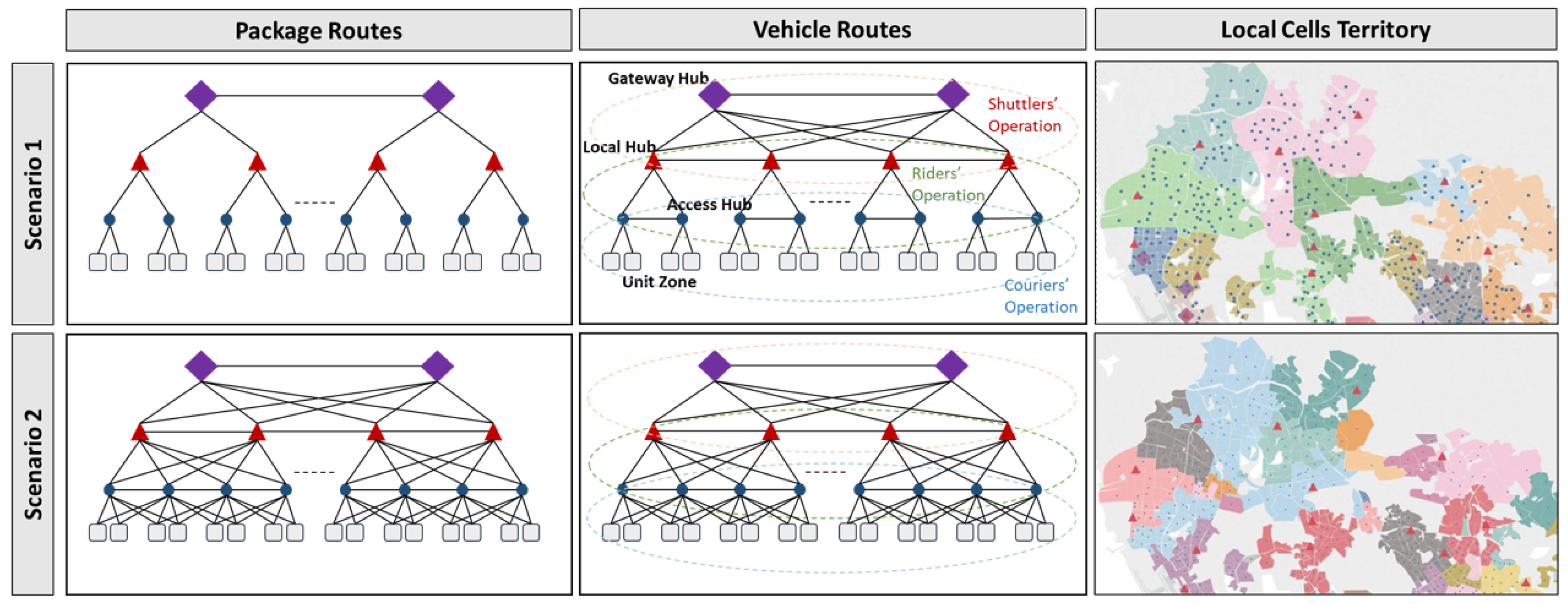
Figure 2), a city is geographically divided into
Unit Zones, which depending on the demand density, may refer to an industrial park, an urban block or campus, a suburban community, or a high-rise in a dense business district. Within an urban territory, a
Local Cell refers to a set of neighboring unit zones, and local cells themselves are further grouped to shape
Areas. As shown in
Figure 2, at the higher tiers of the network, urban areas are further grouped into
Regions and
Blocks which ultimately shape the
World. In this study, our focus is on last-mile delivery, consequently bounding the geographical scope to urban areas. Unit zones, local cells and urban areas are each served by a set of hubs. At the lowest tier,
Access Hubs are used as temporary storage for transitioning packages that are picked up or are going to be delivered at the unit zones;
Local Hubs connect and serve local cells and finally,
Gateway Hubs connect and serve urban areas.
In a standard parcel logistics system, a person/entity (called “Customer” hereafter) initiates package shipping requests through phone, online platforms, or in-person interactions with the delivery company. A package is a closed box which can contain one or several items. Each package has a predefined pickup and delivery point, dimensions (length, width, height) and weight, and is assigned a path when registered to the system. Packages are assigned unique identification numbers by which they can be tracked along their journey through the system. We consider two types of packages including Parcels and Containers:
In this network, we consider a dynamic service offering approach. When a customer submits information on the package he wants to send and the desired pickup window, the system generates a range of viable offers based on the pickup time and anticipated congestion in the network. From these feasible offers, the customer can select an option aligned with their preference, or decline and exit the system. Upon choosing a preferred delivery service, the package is logged into the logistics system, initiating its journey. An initial route is also assigned to the package, which might involve multiple hubs within the network as it travels from the pickup to the delivery point.
Depending on the size of an urban territory, serving pickup-delivery requests may require different sizes of hubs with different operational capabilities throughout the network. In general, less flow density close to the points of service (pickup/delivery) may require smaller hubs where the flow can seamlessly become aggregated; while at the higher tiers of the network where larger flows are being shipped, we may need larger and more equipped facilities to enable efficient flow de-consolidation and consolidation at large-scale [
12].
Due to the relatively low volume of shipments in the first and last-mile logistics, economies of scale are a critical factor for saving costs. As such, we assume most of the hubs have a buffer as well which enables short-term dwelling of packages for aggregation toward subsequent common destinations; This is called freight or truck consolidation. Despite freight consolidation, parcels can be aggregated at a more precise level into containers that travel through several subsequent hubs altogether. Such grouping is called containerized consolidation.
Upon arrival of the packages at the hub (after being unloaded from a truck or dropped by a customer) the package is added to the hub buffer. The buffer is a general term representing a temporary storage space at the unloading docks or loading docks, a dedicated temporary storage space inside the hub, or a temporary space provided for package containerization/de-containerization. Next, if parcels within an inbound container are all heading toward the same subsequent destination, the container is moved to a buffer (which might be at the loading/unloading stage) to wait for a proper outbound truck; On the other hand, if the parcels within the inbound container are heading toward different subsequent destinations, the container is moved to a buffer (this could include shipment from inbound docks buffer stage to the temporary storage), and is opened at a proper time (de-containerized). The individual parcels may dwell for some time at the hub buffer until enough load toward their subsequent destination is aggregated or their target departure time is reached (whichever happens first) to be consolidated and containerized. The new containers will be then waiting in a buffer (which could be the hub’s outbound docks) to be loaded onto a proper truck.
Depending on parcel pickup and delivery locations, we also consider three types of parcels in the system including:
Intracity Parcels: these are picked up from one unit zone in the city and transported to either the same unit zone or a different one within the city.
Outbound Intercity Parcels: these are picked up from a unit zone within the city and, in the scope of our simulation, need to be delivered to one of the gateway hubs so they can be subsequently shipped to a different city.
Inbound Intercity Parcels: in the scope of our simulation they are picked up from one of the gateway hubs and need to be delivered to one of the unit zones within the city.
Once the package route is established, it awaits collection by a driver for shipment to the access hub. Within the access hub, the parcel might be combined with other parcels bound for a shared subsequent destination, all fitting within standardized containers. Another driver then retrieves the container, transferring it to the next hub along the parcel’s journey. Upon the container’s arrival at the subsequent hub, if contained parcels have varied subsequent destinations, the container is opened and its contents are unloaded. These parcels are temporarily stored until consolidation with another batch. Alternatively, if all parcels share the same subsequent destination, the container bypasses the hub (without being opened), proceeding to the loading docks, and awaiting the next stage of transport.
We consider three types of drivers, including (1) couriers, who transfer packages between customers and access hubs, (2) riders, who transfer packages between access and local hubs, and finally (3) shuttlers, who transfer packages between local and gateway hubs.
Figure 3 shows the different types of drivers operating at different tiers of the parcel delivery network.
Each driver uses a vehicle for moving packages throughout the network. Vehicles can be owned by the service provider, acquired under contracts through specific time windows, or requested on-demand whenever extra capacity is required. A combination of these cases is also possible and commonly applicable. At any point of time, a vehicle might be assigned to a specific driver and a task in the system, or stay idle (parked at the last visited hub) until a new request pops up. Only owned and contracted vehicles may remain in the system in an idle state; on-demand vehicles are released as soon as they finish their current task. We consider a heterogeneous fleet of vehicles with different weight and volume capacities and speed parameters. Vehicles’ speed varies depending on the distance to be traveled; with a higher speed considered for longer distances. This is a simple assumption to reflect the fact that traveling longer distances is usually made through highways/freeways in which case the average speed is usually higher compared to local trips which are mostly made through compact neighborhoods.
Upon a parcel’s arrival at its destination access hub, the container is unsealed, and the parcel awaits the delivery courier for transportation to the final delivery location. In instances where a parcel’s destination hub is a Gateway hub (applicable to intercity parcels departing the city), the container is unsealed, and the parcel is transferred to the sorting zone for intercity sorting. As the scope of this study does not encompass the intercity network, the parcel is exited from the system at this point, and relevant key performance indicators (KPIs) are gathered.
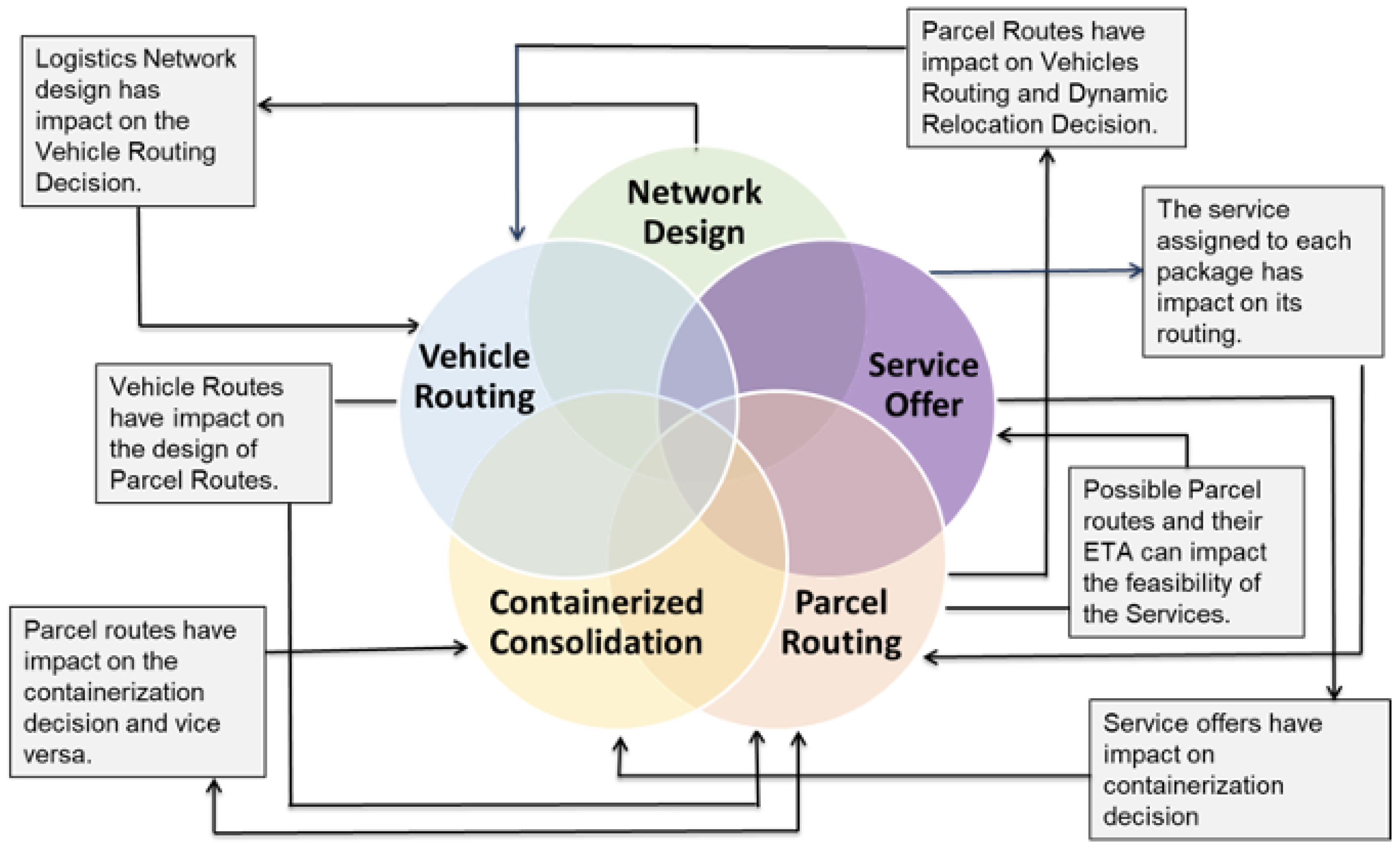
This complex system comprises various stakeholders, each needing to make well-informed decisions that align with the network as a whole. These decisions encompass aspects like logistic network design, service offerings, package routing, driver routing, and parcel consolidation, among others. In the subsequent section, we outline the logical structure, components, and processes that facilitate the implementation of the aforementioned simulation.
3.2. Decisions Architecture
As mentioned earlier, one of the main advantages of the proposed simulation model is its flexibility in modeling different network structures and decision mechanisms by separating the physical movements from the decision-making processes. The physical movements are modeled using discrete-event modeling where changes in an object attribute are modeled through discrete time steps often triggered by another discrete event. On the other hand, to be able to model the individual and local decision-making processes and their interactions, an agent-based modeling approach is used.
The hubs and vehicles are essential assets to the urban parcel logistics for handling and moving the packages. In order to plan and operate hubs and vehicles, a variety of reactive and proactive components are needed to take over actions and critical decisions, respectively. Reactive components are those who do not need intelligent decision-making capability but act according to the instructions they receive (for example drivers and couriers); while proactive components are tasked with making key decisions using a variety of methodologies and policies.
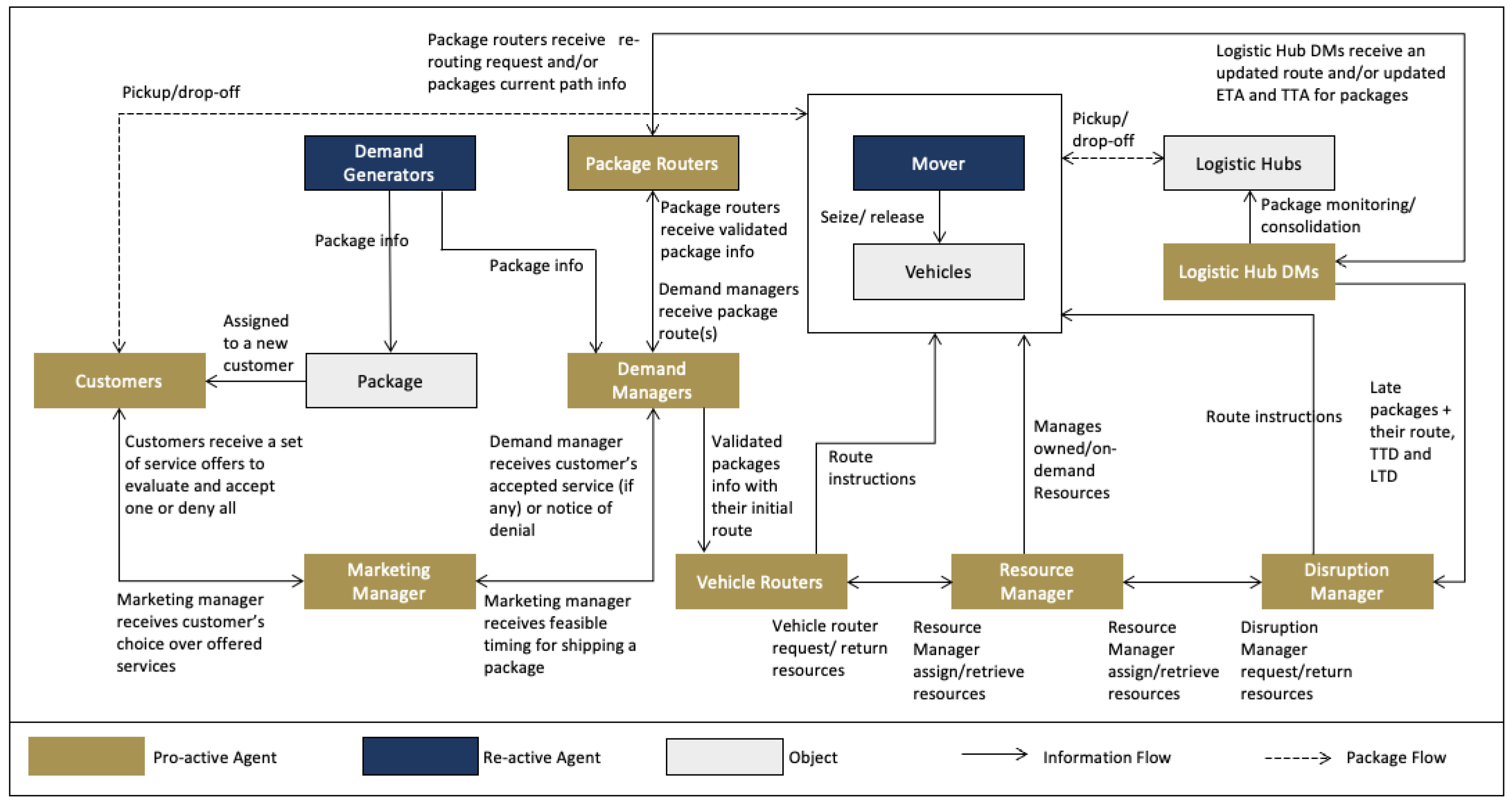
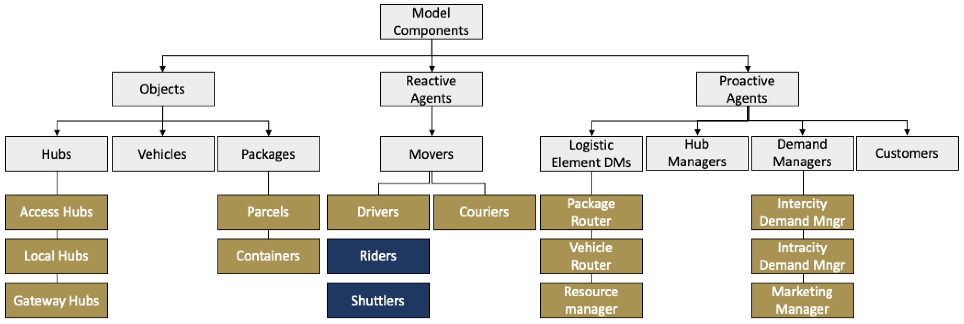
Figure 4 provides an overview of the general framework of our target urban logistic system, different proactive and reactive components, objects, as well as the most important interactions between these components at an aggregate level.
As shown in
Figure 4, the reactive and proactive components may interact based on different types of dependencies, including (1) pooled interdependence: where two activities are conducted in relative independence, but their combined output contributes to an overall joint goal, such as drivers, (2) sequential interdependence: where the output of one activity is the input to another activity, such as demand generators and demand managers, and (3) reciprocal interdependence: where the results of two activities serve as the mutual inputs for each other, such as demand managers, package routers, and vehicle routers. In the remainder of this section, we provide more details on the attributes and functionalities of each of these components.
3.2.1. Reactive Agents
The reactive components in the target urban parcel logistics system correspond to the general class of drivers. Drivers are the human resources who use vehicles to ship packages from one location to another in the logistic network. Similar to the vehicles, we consider three types of drivers including owned, contracted, and on-demand. To mimic real-life conditions, drivers are considered as separate entities from the vehicles, and therefore, a driver may operate different vehicles at different times and a vehicle might be used by different drivers at different times.
We consider different types of drivers for different tiers of the logistic web. Couriers use small-size vehicles (like two-wheel vehicles) and operate within unit zones, dealing directly with the customers; while Riders and Shuttlers use larger vehicles (trucks/vans) and move packages between access-local hubs and local-gateway hubs, respectively. One main operational difference in planning couriers versus riders and shuttlers routes is that although each courier is assigned to serve within a specific unit zone, the exact service locations (customers’ pickup/delivery point) are not known in advance. As such, courier routes cannot be optimized ahead of time. For the shuttlers and riders, however, since the service locations (i.e., hubs) are known and fixed, depending on demand uncertainty, a wide range of decision-making methodologies could be used to provide operational instructions; from the more sophisticated but less responsive offline optimization models to more data-driven and online decision protocols.
Except for the very short-distance pickup-delivery trips (where the package could be directly shipped from its pickup to its delivery point), a package is commonly shipped through a series of transfers between the hubs and the drivers. Along its journey from the pickup to the delivery point, the package is successively loaded to a driver, travels a distance with the driver and is unloaded at a subsequent hub, until it reaches its final destination. The package, therefore, may pass through several hubs and be handled by different drivers before it reaches its final destination.
Figure 5 illustrates the driver processes within the hubs. When a driver arrives at a hub/node, it is first scanned to find if there are any packages in his vehicle to unload; if yes, those packages are removed one by one from the vehicle. If there are no packages to unload, or all such packages are removed from the vehicle, the system checks if the driver’s shift is over; if so, it is then checked if the driver’s vehicle is empty, in which case, the driver is released from its task. If the driver’s vehicle is not empty, the system forces the driver to unload all packages on board even if they were not supposed to be unloaded at the current hub. These packages will be picked up by another driver later to continue their path to their next destination.
If the driver’s shift is not over, the driver receives instructions regarding their next destination. Besides the next destination, the driver also receives information on the packages to load and the route to take toward their next destination. If there are packages to load, those are put into the vehicle one by one. When the loading process is over or in case there are no packages to load to the drivers, they will travel toward their next destination. This whole process is repeated until the driver’s shift is over. A driver might be instructed to spend at least a fixed amount of time at each hub for planning purposes. Also, to fairly distribute several drivers serving the same tour (sequence of hubs) along their service area, extended dwell times may be imposed on a driver at a specific hub.
3.2.2. Proactive Agents
As explained earlier, reactive agents act based on the instructions they receive either as a fixed plan, a rule-based protocol, or a data-driven online command. All such mandates are provided by proactive agents. A proactive agent represents an intelligent decision-making system, like a computer, human, or combination of both that is responsible for making related decisions. One proactive agent may represent several underlying systems all working interconnected to provide an instruction.
To better handle the complexity of modeling the wide variety of involved decisions and their interactions in an urban parcel logistic system, we develop a decentralized decision-making framework, in which decisions are geographically decentralized but mutually informed and interconnected. In the network shown on the left side of
Figure 6, the dark blue areas refer to unit zones; a cluster of nearby unit zones can form a local cell (indicated by red areas) and a set of local cells can form an urban area (shown in green). Relying on the concept of a multi-tier logistic web, we call each unit zone, local cell and urban area, a logistic element. Therefore, each logistic element may include several other logistic elements at its lower tier (if any) and might be contained in several other logistic elements in its higher tier (if any). Each arrow in
Figure 6 indicates a path segment and a sequence of arrows identify an origin-destination path. The right side of
Figure 6 shows how a path may transition between different tiers of the logistic network. This vertical containment includes both topological and operational features, and therefore, serves as an ideal basis for decentralizing the decisions and building the fundamentals for information sharing.
Based on this modeling approach, each logistic element corresponds to a set of decision-makers, including parcel and vehicle routers. Each logistic element decision maker is only responsible for the decisions in his own territory; however, to ensure decisions are efficient network-wide, the local decision-makers must be smartly interconnected through dynamically exchanging information. In
Section 3.2.3 we provide more detailed explanations of the information integration framework over the logistic web.
In what follows, different types of proactive agents that are considered in the proposed urban parcel logistic model as well as their functionalities are introduced. Some of these agents are global and some are local entities given the decentralized network topology.
Customers
We assume each package is requested to be shipped by a unique customer, and therefore, batch shipments are not considered. This is a simplifying assumption, and in practice may not always hold; a customer may place several shipment requests simultaneously, or return to a system in the future to place another shipment request. When a shipment request for an intracity parcel is submitted, the corresponding customer receives a set of viable delivery offers based on the shipment specifications including its pickup and delivery point, its projected path, and the expected delivery speed of the systems at the time of request. From the set of offers received, the customer may select one based on his preferences, or deny placing an order and leave the system if none of the offers are desired. Customer behavior, price sensitivity, and desire for different delivery services can be defined using different rule-based, utility-based, or statistical models. When an offer is selected, the parcel is registered into the system and its delivery path and time are determined.
Unlike intracity parcels, for the intercity inbound and intercity outbound parcels, a pre-determined time-based fixed delivery window is considered. We rely on this assumption since in practice the major part of the journey for intercity parcels (more specifically the intercity portion) is planned by other stakeholders and is out of scope for urban parcel delivery.
To capture the size of a megacity demand for parcel delivery, we generate on the order of one million shipment requests per day on average. Parcels are generated based on a Poisson distribution with a rate where i and j represent the origin and destination zone/hub/city, respectively, d denotes the day of the week and h represents an hour of the day. is the total weekly demand which itself is computed based on yearly, monthly, and weekly seasonality factors retrieved from historical data.
Demand Managers
Demand managers are responsible for receiving new shipment requests and determining the shipment specifications if it was successfully registered into the system. We consider two types of demand managers including Intercity and Intracity demand managers. The Intercity Demand Manager is responsible for determining the delivery time at the customer location for intercity inbound parcels and at the outbound gateway hubs (within the city territory) for intercity outbound parcels. These delivery times are determined based on some rule-based time-dependent policies.
The intracity demand manager, however, has a more extensive set of responsibilities. It is responsible for receiving shipment requests from the customers (for intracity packages) or from the intercity demand manager (for intercity packages). After receiving the requests, it then determines the shipment path, schedule, and delivery time. For the intercity packages, the delivery window is pre-determined by the intercity demand manager. For the intracity parcels, however, this is conducted through a sequence of steps: (1) the intracity demand manager receives a shipment request from the customers or the intercity demand manager, (2) it collaborates with package routers to obtain a real-time estimate on the parcel’s projected path through the system and a worst-case delivery time estimate (based on a given robustness factor) given the capacity of the system at the pickup time, (3) the feasible set of offers are then provided to the customer to receive his preferences, (4) if the customer desires one of the delivery services received, their choice is sent to the demand managers who will finalize the parcels initial path and inform the customer about expected delivery time; if the customer rejects all the offers, their request is removed from the system.
Package Routers
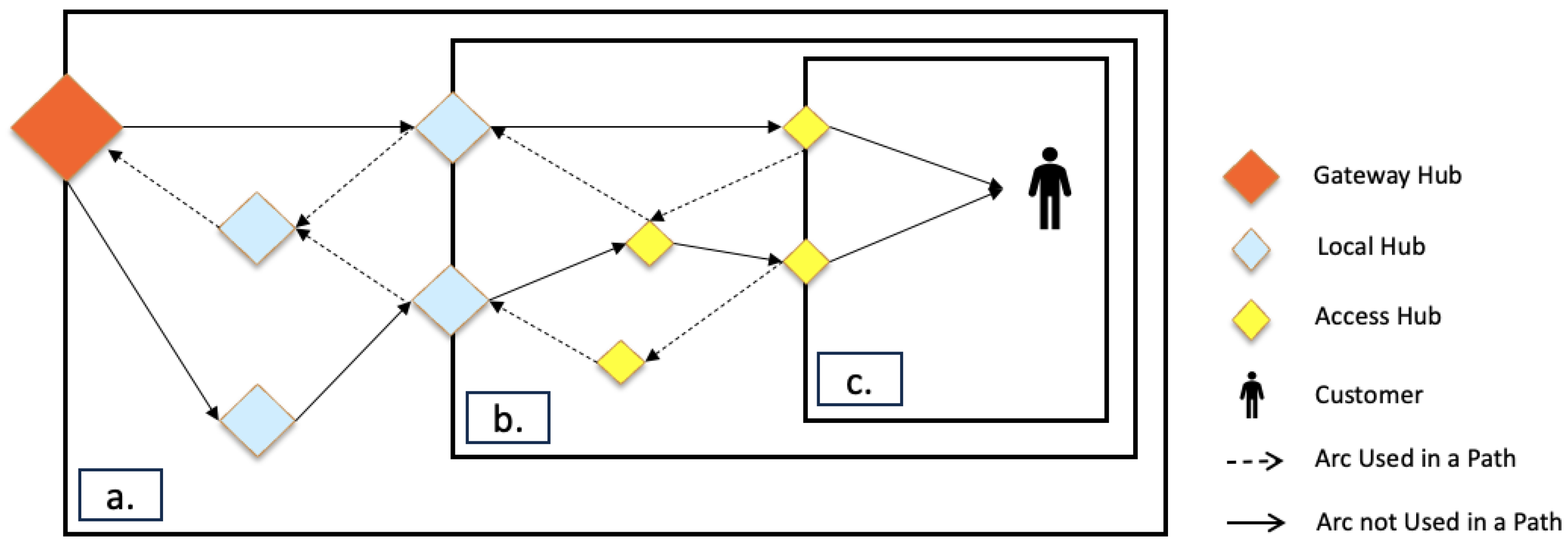
As mentioned in the previous section, after the intracity demand manager receives a shipment request, it sends a query to the package routers to find a set of potential paths from the parcel pickup point to the parcel delivery point. An initial path will be assigned to every parcel registered into the system. Moreover, at any point along the package journey, its remaining path will be updated in case it falls out of the planned route or schedule. The green arrow in
Figure 6 illustrates a typical path for a container shipped through different tiers of the network.
For routing packages through the network, we use a complete enumeration method. This methodology, however, has one downside: as the set of nodes in the network expands and/or nodes become more interconnected, enumerating all possible paths between an origin-destination pair could become heavily resource-expensive and practically infeasible for dynamic planning. To deal with this issue, we leverage the multi-tier structure of the logistic web to decentralize the route planning through the system. This novel approach helps to significantly reduce the computational burden of the dynamic route computation in two ways: (1) instead of assuming a complete network, it limits the inter-nodal links to the nearby nodes (within a zone/cell/area), and (2) allows to systematically decentralize the routing decision with the access to the global information, which reduces the size of the feasible space. To be more specific, for finding a set of paths for a package in the multi-tier meshed network, the following steps are made:
First, a set of feasible sequences of logistic elements is determined (which is called a logistic path) for shipping the package from its current location to its delivery point.
Figure 7 shows examples of logistic paths for intracity, intercity inbound and intercity outbound packages. For instance, for an intracity package, a logistic path might look like: (unit zone 1 → local cell 1 → urban area → local cell 2 → unit zone 2).
Consecutive segments along a package’s logistic path are linked by hubs. These hubs are called pivot hubs as they connect two different logistic elements, enabling the package to move from one tier to its lower or upper tier in the logistic web.
Figure 8 shows an example of a logistic path (
) for an intercity inbound package and illustrates the pivot hubs connecting different tiers. A package enters the first logistic element along its path through its pickup point and exits the last logistic element at its delivery point. The remaining transitions between consecutive logistic elements happen through the pivot hubs.
Next, inside each logistic element along the logistic path, the shortest-time (or fastest) path is computed between every enter-exit hub pair. The enter hub is the one through which the package enters the current logistic element and the existing hub is the one through which the package exists from the current logistic element. Depending on the operating drivers’ cycles and expected travel times on each link, the fastest path between the same pair could be different at different times throughout the day.
Finally, the origin-destination paths are built by attaching all possible combinations of the separate path segments from the package’s current location to its delivery point. The solid arrows in
Figure 8 show two alternative paths for shipping the package from the Gateway hub to the customer location inside the unit zone.
The main advantage of the proposed routing approach is its scalability in terms of network dimensions and connectivity. After a path is built, an expected trajectory for package arrival at every vertex along the path is computed. This is conducted based on a series of time-based statistical distributions for the travel times (between every hub pair) and processing times (at every hub in the system) that are dynamically learned and updated through time (the information integration and sharing features are explained in more details in
Section 3.2.3).
To determine time trajectories for a given route, consider parcel
p as it moves through a series of vertices
, starting from its origin at vertex
and concluding at its destination at vertex
. These vertices may correspond to hubs or specific geographical coordinates associated with customer residences or workplaces. Let
denote the time when parcel
p is prepared for pickup at vertex
. Furthermore, we denote
and
as the mean and standard deviation of shipping times between vertex
and
when the vehicle departs from
at time
t. Correspondingly,
and
represent the mean and standard deviation of processing times at vertex
for parcels arriving at that vertex at time
t. These data are presumed to undergo continuous monitoring, learning, and logging as they evolve with the system’s performance during different daily hours. By assuming a normal distribution for both processing and shipping times and introducing
as a parameter for robustness, we can compute the Expected Time of Arrival (
) and Target Time of Arrival (
) for parcel
p at vertex
with the help of the following equations:
where
and
represent the Expected Time of Departure for parcel
p from vertex
when not accounting for the standard deviation in hub processing time and when considering it, respectively. These values are computed as follows:
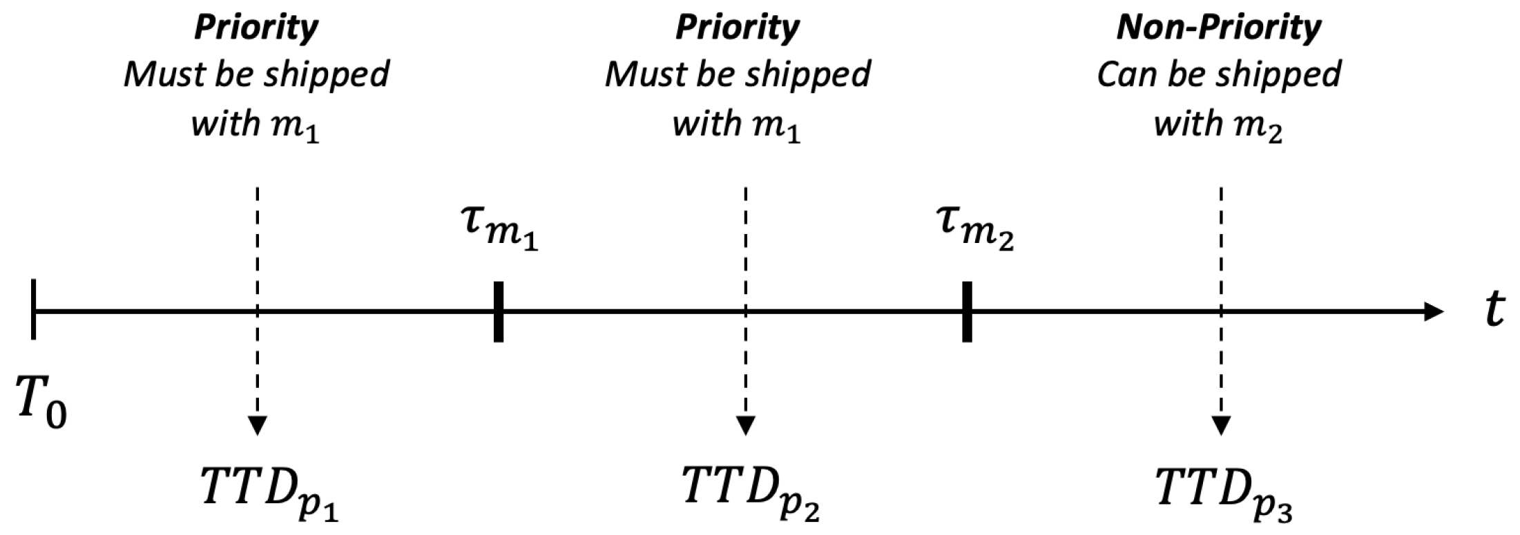
To achieve a specific service level, each parcel
p is only offered services with delivery times exceeding
, the fastest estimated arrival time for parcel
p on its origin-destination route. Let
represent the promised delivery time for parcel
p at its destination. The slack time
is then calculated as
. We define
as the target departure time from vertex
i for parcel
p to ensure timely arrival at its final destination. To utilize the slack time in determining parcels’
at each vertex
along their route, we proportionally distribute this extra time among different segments of the parcel’s path using the following formulation:
Although the
is a very helpful measure for avoiding parcel delay, in some cases it is too conservative. The system needs to have a more clear estimate of how late a parcel is versus its planned schedule to command proper preventive actions. Thus the Latest Time of Departure (
) is computed for the parcels as follows (which informs the latest time a parcel should depart from a hub after which with a high chance it is going to be late at its final destination):
Vehicle Routers
Each logistic element has a vehicle router as well. A vehicle router decides on the route that each vehicle takes, manages the acquisition and release of required drivers and vehicles (in communication with the resource manager), tracks the working shifts for drivers, and assigns specific pickup∖delivery packages or re-positioning hubs to the drivers. Depending on if the logistic element is a unit zone, local cell, or urban area, a vehicle router may deal with couriers, riders, or shuttlers, respectively.
For this study, shuttle cycles are optimized offline, given the average flow through the network, and using the methodology introduced in [
44]. To account for demand seasonality and flow pattern throughout the day, the shuttle’s activity throughout a day is divided into three regimes: (1) morning regime from 5 am to 11 am, (2) midday regime from 9 am to 6 pm, and (3) afternoon regime from 12 am to 12 pm. To design shuttle cycles, a path is first generated for each commodity in each regime using an IP-based formulation aimed at minimizing (variable) cost of the arcs while maximizing the consolidation opportunity in the network. Given the initial set of commodities routes obtained at phase 1, an IP model is used to generate cycles that provide the required minimum truck coverage for the arcs used by commodities paths while incurring the minimum cost. Next, commodities paths are restructured to find the shortest time-feasible path for each commodity on the cycle network built on each regime. Finally, a proper transition between cycles in consecutive overlapping regimes is determined [
44].
Similar to shuttlers, rider routes are designed in multiple regimes (8 am–4 pm and 4 pm–11 pm) to adapt to the demand seasonality. Riders provide shipping capacity to move packages between access hubs and local hubs. Each route starts at a depot (in this case, a local hub), serves several pickup/delivery locations, and ends at the depot. Rider cycles are designed offline, considering the average flow, and using a two-stage optimization model introduced in [
45] which is aimed at minimizing the number of riders and the average parcel transfer time.
Courier’s operations involve more dynamics compared to the riders and shuttlers. Couriers serve unit zones by picking up and delivering packages at customer locations. Since the pickup and delivery locations and the time packages arrive in the system are not known preliminary, couriers must be routed dynamically to be utilized at their best capacity. In this study, we use a simple first-come-first-served policy for serving packages. Furthermore, every time a package is registered to a unit zone for pickup/delivery, it is assigned to a courier with the least load-to-serve to ensure fairness.
The designed rider and shuttle cycles, also include information on the number of drivers and the type of vehicles operating on each cycle. Based on this information, each logistic element sends requests (to the Resource Manager) for the proper number and type of drivers to be assigned to the cycles in each regime.
Resource Managers
All drivers and vehicles, when added to the system, are registered in a directory that will be managed by the resource manager. The resource manager keeps a record of every driver and vehicle specification and has access to their current status (working/idle), current location, and upcoming tasks. The resource manager receives requests from the vehicle routers for seizing specific numbers and types of drivers and responds to the requests based on the availability of resources and the specific resource allocation protocols (for example allowance of using on-demand resources and any limit associated with that).
In order to find and assign a driver (and a vehicle) to a task, the resource manager first searches for idle vehicles (of proper size) near the point of request (based on an input neighborhood distance threshold). If no vehicles of proper size exist in the vicinity to the point of request, depending on the system preferences, an on-demand vehicle might be acquired or the request is denied. When the vehicle is determined, the resource pool manager searches (this time at a predefined distance to the vehicle) to find any free driver with the target specification (courier/rider/shuttler). If one is found, the vehicle will be assigned to the driver. The driver picks up the vehicle and then moves toward the point of request. Similar to vehicles, if no driver with the target specifications exists in the vicinity of the vehicle, one might be requested on demand. We also assume that the time for the driver to reach the vehicle is negligible.
Hub Managers
Each hub has a manager that performs several fundamental tasks. One of the main responsibilities of the hub managers is monitoring packages that pass through the hub, which includes (1) checking packages arriving at the hub to ensure they are on the right path and schedule, (2) continuously tracking packages sitting at the hubs to guarantee their timeliness, and (3) taking corrective actions if a package falls out of its planned route or schedule. In the proposed simulator, we assume misrouted (or lost) packages are re-routed and delayed packages are put in priority for being loaded to the first arriving truck that heads toward the package’s next destination.
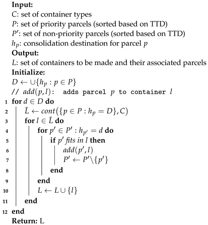
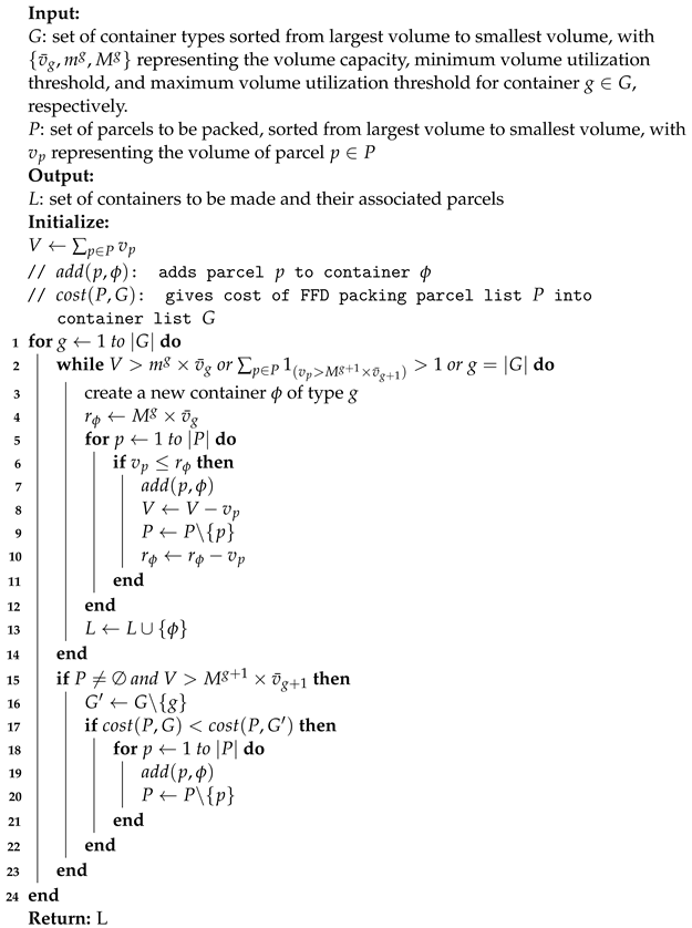
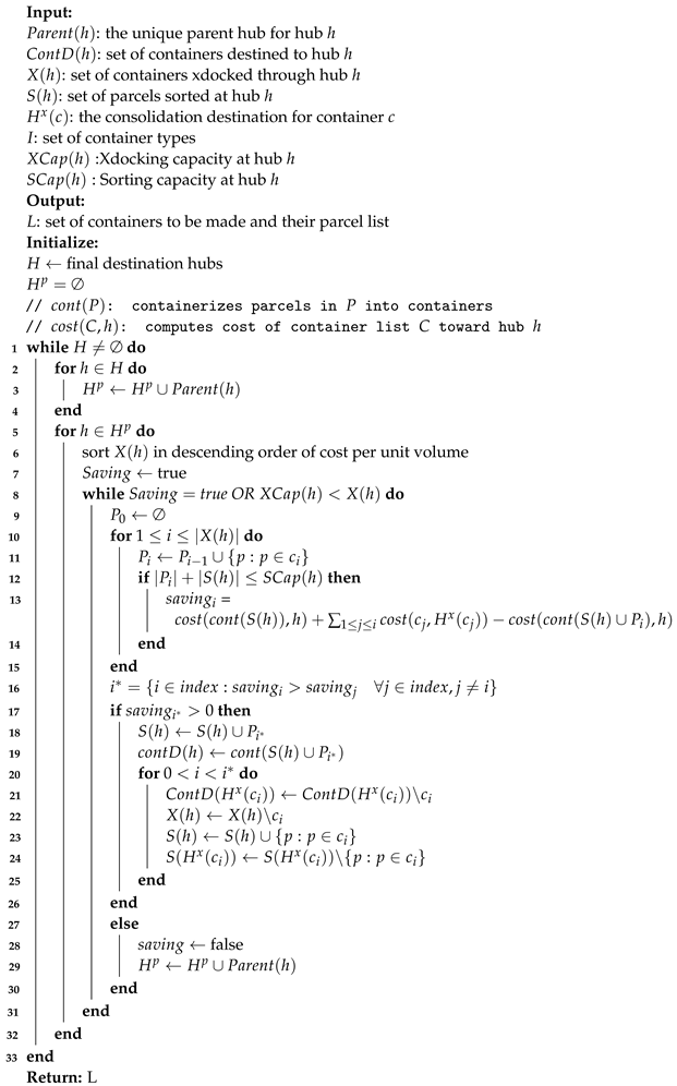
The hub managers also play a crucial role in consolidating and containerizing packages. This involves prioritizing parcels for loading based on their scheduled departure times from the hub, grouping parcels with similar service requirements and shared destinations, and placing these groups into appropriately sized modular containers. Containerized consolidation enables parcels to skip the sorting process at multiple intermediate hubs and offers substantial advantages in terms of reducing handling and transit costs [
46].
3.2.3. Information Sharing and Integration
Many of the policies and methodologies, introduced in the previous sections, for making critical decisions within the urban parcel logistics system heavily rely on live network data availability. Key parameters, including hub processing times at various hours of the day and travel times along routes, are initially established or computed and then dynamically updated during the simulation process. As packages traverse through hubs or drivers travel along routes, pertinent data are collected and stored for updating parameter distributions. Consequently, decisions are continuously informed by the latest data, reflecting the system’s recent performance whenever they need to be made.
To make the storage and access to this large pool of data feasible, we leverage the web structure of the network and the agent-based modeling features, to track the information in a distributed manner and save it locally while providing access globally and in real-time.
Figure 9 shows the difference between a centralized and decentralized network in terms of data storage and access, responsiveness, and decision-making scale and complexity.
Such real-time information can bring many advantages to the system specifically when making real-time decisions. Most of the decisions made in the system are distributed between local agents, and therefore, each individual agent does not need to have access to all the information across the system. Access to such large pools of data not only is not necessary but also makes it time-expensive to find relevant information and almost impossible to make dynamic decisions. Instead, we collect data inside each logistic element and also inside each logistic hub. Due to the vertical containment of the logistic elements, the data are accessible between overlapping logistic elements and thus throughout the network by simply knowing the correct path to the data storage location (very similar to the package routing protocol). This structure is not only efficient in terms of live data tracking and storage, but also fast for data retrieval upon receiving a query.
In previous sections, we introduced time metrics such as ETA, TTA, TTD, and LTD, and described how they are computed for each hub along a package’s route after the journey commences. As the package begins its transit and progresses through the system, these data are continuously updated at each intermediate hub. Additionally, package arrival notifications are dispatched in advance to hubs along the package’s route and are dynamically adjusted in response to any changes. Similarly, for each vehicle traversing the system, real-time updates are dispatched ahead of time to inform hubs along the route about expected arrival times, vehicle and driver details, and the parcels on board. As previously mentioned, hub managers utilize this information when strategizing parcel consolidation and containerization.
3.3. Simulation Model
To model the urban parcel logistic system introduced in
Section 3.2, we use the architecture presented in [
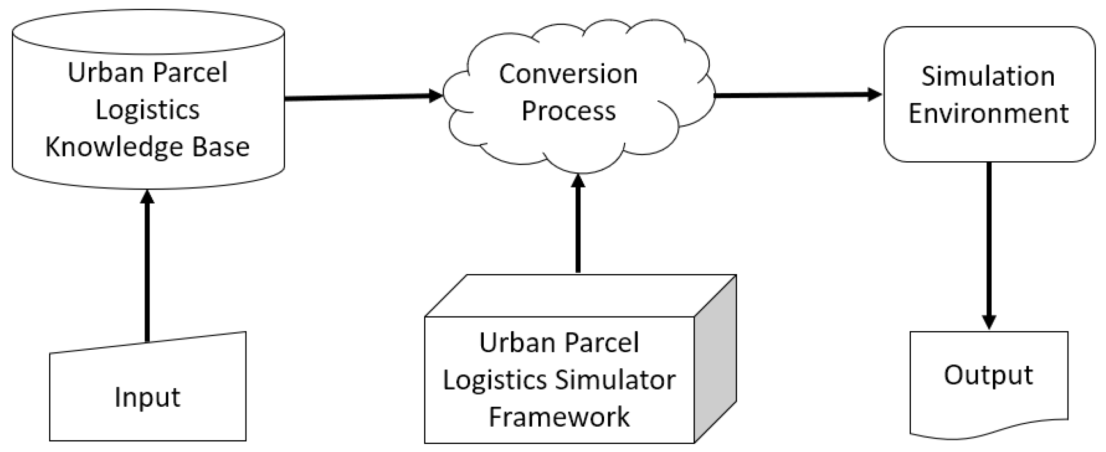
47] and propose a simulator framework that relies on the general system’s definition and is independent of any specific urban parcel logistic configuration (see
Figure 10). Such an architecture allows for a highly flexible framework that can simulate various scenarios with different strategic, tactical, and operational configurations. The knowledge base in
Figure 10 refers to all the scenario-specific information corresponding to a user-defined configuration (Inputs). Through a conversion process, these data are translated into a language understandable by the simulator framework, creating the simulation environment. The output of a run on a simulation environment is a set of predefined key performance indicators represented through logged data files and dashboard visuals.
The simulator’s general framework is designed based on several key components (illustrated in
Figure 11). Following the previous section, these components are categorized into three main groups, proactive agents, reactive agents, and objects. The main proactive agents in the designed framework correspond to the Customers, Demand Managers, Hub Managers, and Logistic Element Managers. The reactive agents refer to the general class of drivers that are used for transferring packages between hubs/customers. Finally, objects include Hubs, Vehicles, and Packages.
Each main component of the system extends into several other components of different types which in the coding language are called sub-classes.
Figure 11 shows different sub-classes under each component of the framework which are explained earlier in this section.
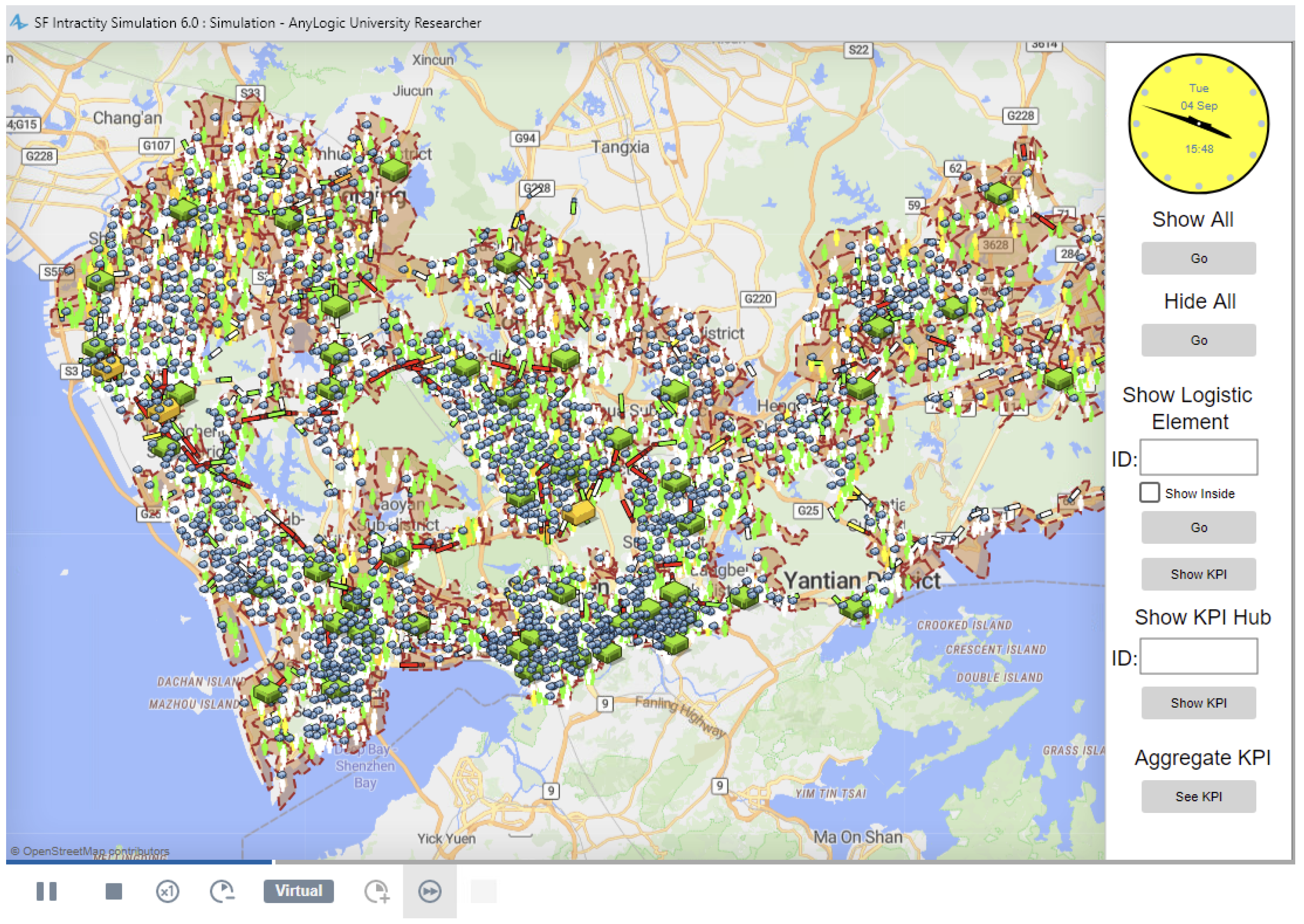
The model is constructed using AnyLogic simulation software, version 8.8.1. AnyLogic was selected due to its proficiency in combining various simulation libraries, encompassing discrete-event, agent-based, and system-dynamics methodologies. AnyLogic employs Java as its foundational language, which allows for the smooth integration of optimization models through the Cplex library. An additional significant advantage of AnyLogic is its capacity to interact with a wide array of software programs, facilitating seamless input and output data exchange.
