Abstract
Backgrounds: The transportation system within any mining project, which is responsible for delivering extracted ore to the crushing units or wastes to the wasting dumps as the destinations, poses a significant challenge in mining processes. On one hand, there are various transportation systems, notably the Truck–Shovel, the traditional method, and relatively newer and less common In-Pit Crushing and Conveying (IPCC) systems. On the other hand, choosing the most suitable system for a specific mining project depends on various factors, with technical aspects being one of the most critical. While there is extensive research on the Truck–Shovel system from a technical perspective, there is relatively limited research on IPCC systems. Methods: This research aims to carry out a comparative analysis of different transportation systems, encompassing Truck–Shovel, Fixed In-Pit Crushing and Conveying (FIPCC), Semi-Fixed In-Pit Crushing and Conveying (SFIPCC), Semi-Mobile In-Pit Crushing and Conveying (SMIPCC), and Fully Mobile In-Pit Crushing and Conveying (FMIPCC) systems. To achieve this goal, a technical index is introduced, which is based on three elements: the availability and the utilization of the system, as well as the consumption of power. This index will be developed as a system dynamics model, enabling the observation of each system’s performance throughout the operational lifespan of the mine. Results: Ultimately, based on the proposed method, the most effective transportation system based on the defined technical index can be identified at any time of the project. In this research, the Truck–Shovel system generally selected as the most preferred transportation system, except for two different periods. Conclusions: This study could successfully perform the selection among different transportation systems. Nevertheless, it was modeled and performed in a deterministic environment, but still the stochastic nature of the processes can be another topic of research.
1. Introduction
The Truck–Shovel system in open pit mines, which is recognized as the prevalent transportation system, is widely acceptable because of its technical features, particularly its flexibility. This allows planners the freedom to consider various production plans and scenarios [1,2]. However, in IPCC systems, the technical aspects in comparison to the Truck–Shovel system have not been significantly investigated, and there are relatively few relevant studies.
The primary and most critical technical challenge associated with IPCC systems is their suitability for a project, which is primarily dependent on a set of factors. These factors predominantly include the efficiency of the systems, their integration with the drilling and blasting, and the sequence of the bench operation, simplicity of relocation, adaptability in the reserve’s change, expandability, and interoperability with other parts of the system [3].
The second issue concerns the mine design problem, which can undergo a significant transformation when using these systems. For instance, the pit shell design and production planning in short- and long-term concepts may vary in the context of a mining project that is operated by IPCC systems instead of a Truck–Shovel system [4,5,6,7,8,9,10]. Additionally, the potential combinations of the Truck–Shovel and IPCC systems and their effect on the mine design were thoroughly investigated. In a study conducted on a deep gold mine, the Truck–Shovel system was employed for excavating a “box cut” in the first phase followed by the utilization of the FMIPCC system for a “parallel and radial pushback” in subsequent phases [11].
The optimum location and relocation plan of IPCC systems are other technical issues. Various studies have explored the IPCC system’s optimum location from different perspectives. These include assessing the truck cycle time by simulating the loading and hauling cycle [12], addressing the single hub location problem for minimizing the haulage costs and environmental considerations [13], and employing heuristic and operation research (OR) methods such as the dynamic facility location problem [14] and transportation problem [15,16]. In addition, several case studies examined the transition point, which is optimal, from the Truck–Shovel to IPCC system for a copper mine [17] and an aggregate mine, with a focus on minimizing haulage distances [18].
Some studies evaluated the presence of IPCC systems in mining operations and examined their influence on various facets of the mining process, as these interactions can highly affect the annual output of IPCC systems [19]. Other research compared the availability of the Truck–Shovel and IPCC systems in terms of utilization time, operating time, and valuable operating time [20,21]. In these studies, it was noted that IPCC systems exhibited less flexibility compared to the Truck–Shovel system, while conveyor belts demonstrated higher operating efficiency [21].
Decision-making tools and techniques are developed and used in some branches of the mining industry such as underground mining methods specifically in coal mines [22,23,24]. Nevertheless, for the Truck–Shovel and IPCC systems, no study or research has been carried out.
As it can be noticed in the literature, a single factor such as production planning, availability, or optimum location, and a relocation plan of the Truck–Shovel system or IPCC systems are mostly studied; however, some other factors, for example, power consumption, are neglected in both systems. In addition to this, the interactions of these components as an integrated system are not considered. These shortages could lead to an imprecise representation of transportation systems.
This study tries to fill the gap in a way that not only defines transportation components as a system through system dynamics modeling, but also describes a technical index with which a decision-making system will be provided for selecting the most appropriate and effective transportation system. In general, the academic contribution of this research can be described as the development of a system dynamics model that takes into account three critical factors: system availability, utilization, and power consumption. This contribution is expected to provide practical assistance to managers when making decisions regarding the selection or planning of transportation systems in mines.
2. Materials and Methods
In this section, two main concepts used in this research will be discussed. Firstly the “System Dynamics Modeling”, in which the modeling environment and parameters are briefly described. Secondly, the idea of “In-Pit Crushing and Conveying (IPCC) Systems”, in which their different types and differences will be explained.
2.1. System Dynamics Modeling
System dynamics involves modeling, simulating, and analyzing complex systems to assess how they evolve and change over time [25]. This method was initially developed in the 1950s to help managers enhance their comprehension of how the processes have evolved. In contemporary times, system dynamics finds application across different sectors for the analysis and formulation of policies. Unlike statistical modeling, where time is not a factor in the simulation, system dynamics modeling focuses on understanding the dynamic nature of systems, encompassing their evolution over time. In this approach, modelers aim to identify behavioral patterns exhibited by key system variables and, subsequently, develop a model with the capacity to simulate these patterns. Once a model possesses this capability, it can serve as a prototype for evaluating various scenarios [26]. Generally, there are two main categories of system dynamics models: “open systems”, where outputs do not impact inputs, and “closed systems”, where outputs can influence inputs. Each system dynamics model comprises constants, auxiliaries, stocks, flows, and feedbacks.
A system dynamics model comprises parameters categorized into two groups: constants and auxiliaries. Constants remain permanently fixed throughout the system’s processing, whereas auxiliaries are defined as equations involving various constants, and they may undergo changes during the system’s processing [26].
The fundamental components within the realm of system dynamics are denoted and counted as stocks and flows. Stocks serve as indicators of accumulated values over time, represented by their “level” or “state”, which effectively encapsulates the system’s condition at any given moment [27]. Stock examples may include metrics such as the count of injuries, fatalities, lost time incidents, accidents, and more. The flows move directly into and out of these stocks, influencing their levels and reflecting the dynamic “rate of change” within them [27]. Emission rate and particulate matter rate, among others, exemplify flows. It is essential to specify the unit for these rates as quantity per time, enabling the accumulation of stocks over time. The graphical representation of a stock and flow diagram is as Figure 1. The typical formulation for a stock–flow diagram encompasses the following general equation:

Figure 1.
An illustrative depiction of a basic stock and flow diagram.
While stocks and flows are essential elements for creating dynamic phenomena, they do not encompass the entirety of system dynamics. To provide a more accurate explanation, it is crucial to understand that in real-world systems, stocks and flows interact within feedback loops. These feedback loops may comprise various types of feedback mechanisms and occasionally feature nonlinear connections, leading to unexpected and counterintuitive behaviors [26]. Figure 2 illustrates a straightforward stock–flow system including feedback, illustrating the connection between a stock and its inflow.

Figure 2.
Feedback loop in a stock–flow diagram.
In general, closed systems are governed by positive or negative feedback loops. Positive loops represent processes that reinforce themselves, where an action produces a result that further stimulates the action, ultimately resulting in an increase in both the action and the result. These positive feedback loop processes render systems unstable and drive them to alter their existing state. Consequently, they play a key role in either the growth or decline of systems [26]. Conversely, negative feedback loops characterize processes oriented toward achieving goals, generating actions that either guide a system toward a desired state or maintain it within that state. Typically, processes involving negative feedback loops contribute to the stabilization of systems, although there is a possibility of occasional destabilization through oscillations [26].
The effectiveness of a system dynamics model greatly depends on the developer’s approach to system thinking. It means whenever more parameters and their relations can be found, the model will be more accurate and approach the desired results. It is also possible to add or remove any parameter in the model; however, it is crucial to find its right position, equation, and relation to others.
In this study, Vensim® 6.2 was used to build and run the system dynamics modeling. This software offers an illustrative as well as descriptive environment for introducing and modeling all the components mentioned above.
2.2. The Concept of In-Pit Crushing and Conveying (IPCC) Systems
In the Truck–Shovel system employed in open-pit mines, materials are moved from within the pit to external destinations, typically involving a crusher station for ore and a waste dump for discarded material. In contrast, with In-Pit Crushing and Conveying (IPCC) systems, the crusher station is situated inside the pit, and the crushed ore or waste is conveyed to its designated location via a conveyor belt. The concept of implementing this system was first introduced in Germany in 1956 [28]. It served as a substitute for the traditional surface mining transportation system, known as the Truck–Shovel system [29]. It typically addresses various shortcomings of the Truck–Shovel system, such as minimizing operational expenses [30], primarily achieved through the reduction in both workforce and fuel consumption [11]. Furthermore, from a safety standpoint, conveyor belts, being integral components of IPCCs, demonstrated a reduced incidence of accidents, injuries, and fatalities [31]. Despite these benefits, there are still certain perspectives regarding its flexibility [20], reliability, and efficiency [21].
In general, this system can be classified into four distinct types: (1) Fixed In-Pit Crushing and Conveying (FIPCC) system, where the crusher remains stationary throughout the mine’s lifespan. Typically, the FIPCC system is positioned near the pit rim or inside, unaffected by ongoing mining activities. (2) Strategic Fixed In-Pit Crushing and Conveying (SFIPCC) system, strategically positioned at a key junction within the pit and predominantly fed by mining trucks. Relocating this system requires the disassembly of the entire crusher station into multiple parts or modules. (3) Semi-Mobile In-Pit Crushing and Conveying (SMIPCC) system, typically situated at the operational level and capable of being fed by trucks or loaders from various loading points. (4) Fully Mobile In-Pit Crushing and Conveying (FMIPCC) system, capable of continuously changing its location and leveraging an integrated transportation mechanism [32].
FIPCC, FMIPCC, and SMIPCC share a common characteristic where trucks handle the feeding process, and a conveyor belt is used to transfer crushed material from the pit. Essentially, these systems integrate two types of transportation equipment: trucks and conveyor belts. In contrast, FMIPCC utilizes shovels for direct feeding, with the conveyor belt dedicated to transporting the crushed material.
2.3. System Dynamics Modeling for Introducing Technical Index
System availability, utilization, and power consumption were defined as the building blocks of the system dynamics model as well as the technical index. The first two components are chosen because of their importance, as found in the literature, while the latter is newly introduced. All these factors can finally give a better comparability of transportation systems variants, which gives this capability to designers in making decisions about selecting one system over another. In the following sub-sections, the development of these factors in a system dynamics model will be explained.
2.3.1. System Availability
Availability for mining equipment refers to the downtime that includes any activities causing a halt in planned production, such as unscheduled time, scheduled maintenance, setup, and adjustment periods, among others [33,34,35,36]. However, the availability of a system, which is constituted of different components that have interactions together, can be conducted according to the configuration of the system, specifically serial, parallel, and hybrid configurations.
In a serial configuration, the components of the system are linked in a sequential format. This means that for the availability of the system, all the components must be available [37]. The total availability is the result of the multiplying of individual components’ availabilities, and for a system with n components will be as Equation (2) [37].
In a parallel setup, the entire system remains operational as long as at least one of its components is accessible, ensuring overall availability [37].
Unlike the serial configuration, where the functioning of the system relies on all components, the parallel configuration falters if any of its components fail. The overall availability of a system with n components is calculated by Equation (3) [37].
When a system is composed of both serially and parallel-configured components, it forms a hybrid configuration [37]. In this scenario, concurrent components need to be computed simultaneously, and the outcome is tallied and incorporated into the system as a cohesive unit. This procedure should persist until the determination of the integrated system’s availability.
The Truck–Shovel system is established exclusively through the use of trucks and shovels, and it is regarded as a non-continuous system [38]. There exist four distinct states for a Truck–Shovel system (Table 1). Although States 1 and 3 are unlikely to happen, these states are referenced to encompass the entirety of available states. Furthermore, it is presupposed that the crusher, conveyor belt, and spreader situated outside the pit in this system do not impact the availability of the Truck–Shovel system. This is because the material can be deposited in the stockpile if any component of the crushing unit (i.e., crusher, conveyor belt, and spreader) is unavailable.

Table 1.
Four states of Truck–Shovel system.
In the FIPCC, SFIPCC, and SMIPCC systems, the states mirror those of the Truck–Shovel system, with the exception of the crusher and the conveyor belt, which are partially situated within the pit. Additionally, the crusher, conveyor belt, and spreader operate seamlessly as an integrated system, such that a failure in any of these components will result in the entire system’s failure [32]. The equations provided can be utilized to compute the system availability for each state (Table 2).

Table 2.
The states of FIPCC, SFIPCC, and SMIPCC systems.
In the FMIPCC system, functioning without the use of trucks, shovels directly supply material to the mobile crusher. Two distinct states can be outlined for this operational configuration (Table 3).

Table 3.
FMIPCC system’s states.
2.3.2. System Utilization
The utilization of any equipment is characterized as the overall time it is accessible for use, excluding any periods of downtime such as shift changes or meal breaks. In line with this, the overall system utilization relies on its individual components. When it comes to series and parallel systems, utilization can be expressed through the following equations:
2.3.3. Power Consumption
Power consumption within transportation systems refers to the energy expended by the various components involved in transporting materials from their point of origin to their destination. Consequently, trucks and conveyor belts, serving as primary elements in these systems, must generate adequate rimpull and effective tension, respectively, to facilitate material transfer. To assess the power consumption of different transportation options, calculations were conducted for both truck power and conveyor power.
Equations (6) and (7) express the overarching equation for determining the power of a truck in both loaded () and unloaded () modes, respectively [39].
where RLT and RUT are the rimpull of the loaded and unloaded truck; SLT and SUT are the loaded and unloaded truck speeds, respectively; and g is the gravitational acceleration. The formula for calculating the rimpull of loaded () and unloaded () trucks is as follows [40]:
where mT, mL, G, and Rr are truck mass, load mass, road grade, and rolling resistance, respectively. The incline of the road may vary, either positively or negatively, depending on whether trucks are ascending or descending, respectively [41].
The conveyor belt, as one of the major parts of the IPCC systems, is responsible for the power consumption in the transportation systems. Accordingly, it is crucial to evaluate its contribution to the power consumption. One of the most acceptable equations for estimating the power of conveyor belts () is as follows [42]:
where Te and V are the belt tension in lbs and the belt speed in fpm, respectively. The belt tension can be calculated as the following equation [42]:
where L is the length of the conveyor (ft); Kt is the ambient temperature correction factor; Kx is the factor used to calculate the frictional resistance of the idlers and the sliding resistance between the belt and idler rolls (lbs/ft); Ky is carrying run factor used to calculate the combination of the resistance of the belt and the load to flexure as they move over the idlers; Wb is the weight of belt (lbs/ft); Wm is the weight of material (lbs/ft); H is the vertical distance the material is lifted or lowered (ft); Tp is the tension from the resistance of the belt to flexure around pulleys and the resistance of pulleys to rotate on their bearings, total for all pulleys (lbs); Tam is the tension from the force to accelerate the material continuously as it is fed onto the belts (lbs); and Tac is the total tensions of conveyor accessories (lbs).
2.3.4. Technical Index Equation
In order to simplify the assessment of different transportation systems based on a technical index (TI) standpoint, an equation is derived from the parameters mentioned earlier. The rationale behind this equation is that systems exhibiting greater availability and utilization are favored over others (a positive correlation). Conversely, systems with lower power consumption are considered superior (an inverse relationship). As this index will be utilized to compare the resulting technical indexes from the Truck–Shovel and IPCC systems, no significance coefficient has been assigned to these factors. As a result, we can formulate the following equation:
2.4. Case Study
A case study, a hypothetical copper open-pit mine with technical specifications outlined in Table 4, was examined. These specifications are categorized into various sections, encompassing the mine and mill, trucks, shovels, IPCC systems, spreaders, IPCC relocation, and conveyor belts. It is crucial to note that these specifications exclusively pertain to ore. In essence, our assumption is that the selection of the transportation system will be conducted based on the ore reserve.

Table 4.
Technical details for the theoretical copper mine.
3. Result and Discussion
In the following, the factors determining technical index are discussed, which are system availability, system utilization, and power consumption.
3.1. System Availability
Figure 3 illustrates that Truck–Shovel and FMIPCC systems exhibit the highest and lowest system availabilities, respectively. In the case of the former, availability starts at 99.45% in 2016 and gradually increases to 99.73% by 2049. Meanwhile, FMIPCC maintains a fixed availability rate throughout its lifespan, at 57.95%. This discrepancy can be attributed to the usage of trucks in these systems, with the Truck–Shovel system having the highest truck utilization while FMIPCC relies on zero truck utilization. Furthermore, within the Truck–Shovel system, the hybrid configuration offers greater availability compared to the serial system. This can be attributed to the presence of a parallel component in the hybrid system, allowing it to continue operations even when one or more components are unavailable. Other systems, such as FIPCC, SFIPCC, and SMIPCC, which combine trucks and conveyor belts, exhibit system availabilities falling between those of the Truck–Shovel and FMIPCC systems. Notably, the SMIPCC system demonstrates lower availability than the FIPCC and SFIPCC systems, primarily due to a smaller fleet of trucks.
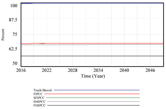
Figure 3.
Availability of systems in various transportation systems.
3.2. System Utilization
Unlike the FMIPCC system, the Truck–Shovel system exhibits lower system utilization, standing at 86.6%. This is primarily attributed to the greater number of trucks, leading to increased stoppage times. Nevertheless, boosting the truck count is expected to raise the average system utilization from 83.7% in 2016 to 85.72% in 2049 (Figure 4). FIPCC, SFIPCC, and SMIPCC systems exhibit closely aligned values, though, in certain intervals, one may indicate higher system utilization compared to the other two.
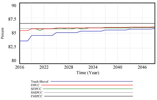
Figure 4.
Utilization of systems in diverse transportation systems.
3.3. Power Consumption
The total power consumption is determined by combining the three parameters of conveyor belt power, loaded truck power, and unloaded truck power.
Figure 5 illustrates the power consumption of conveyors in various transportation alternatives.
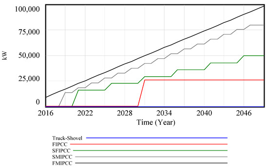
Figure 5.
Power consumption of conveyor belts for various transport applications.
In the Truck–Shovel configuration, where a conveyor belt is absent, the power consumption related to conveyor belts is unequivocally zero. Conversely, in the FMIPCC system, power consumption progressively rises with the conveyor belt’s length. This reliance on conveyor belt power is influenced by the conveyor’s length, which, in turn, is affected by the relocation of IPCC systems throughout the mine’s operational life. For instance, in this study, the FIPCC system underwent relocation only once in 2031, shifting to a lower elevation. Consequently, the overall length of the conveyor belt increases. However, this scenario deviates for SFIPCC and SMIPCC systems due to their relocation intervals of five and two years, respectively.
In comparison to the Truck–Shovel system, which stands out for its substantial consumption of loaded truck power, the FMIPCC system exhibits a clear advantage with zero truck power consumption. This disparity is primarily due to the absence of trucks within the FMIPCC system, as illustrated in Figure 6. Moreover, it is clear that extending the transportation route for moving ore from mining sites to the crusher leads to an increased requirement for truck power. The logic here is straightforward: systems employing a greater number of trucks in their operations inherently incur higher power consumption. In the hierarchy of power consumption, the Truck–Shovel system takes the lead, followed by the FIPCC system, the SFIPCC system, the SFIPCC system, and the SMIPCC system, in sequential order.
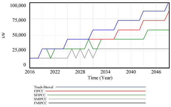
Figure 6.
Power requirements of loaded trucks for various transportation scenarios.
As unloaded trucks traverse a route from the pit’s upper to lower regions in this study, the road incline will be considered with a negative sign in Equation (7). Consequently, the power of an unloaded truck will be in the negative range, which shows the reverse direction of applying energy through braking (Figure 7).
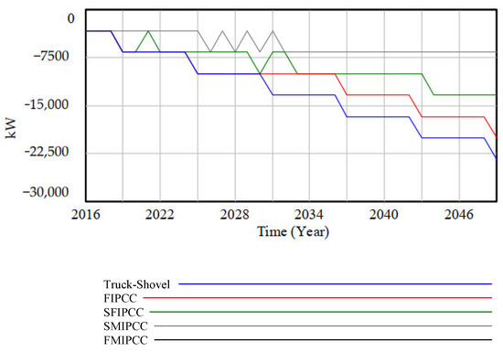
Figure 7.
Power consumption of unloaded trucks in various transportation systems.
3.4. Technical Index
The technical index of different transportation systems is shown in Figure 8. As depicted in this figure, the technical index for the Truck–Shovel system except for the two periods of 2016 to 2018 and 2020 to 2022, is higher than others. It has a very close competition with FMIPCC till 2023 and the technical index difference for these two systems is very low in this period (Table 5). However, after 2023, this difference starts to increase, and the Truck–Shovel system introduces itself as the best transportation system from 2023 to the end of the project. The other three transportation variants are considerably different from the first two systems, but their quantities are close to each other (Table 5).
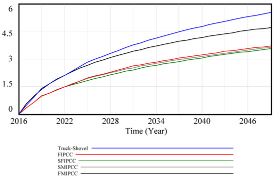
Figure 8.
Technical index for different transportation systems.

Table 5.
Technical index ranking for various transportation systems.
4. Conclusions
The Truck–Shovel and IPCC systems, established as viable transportation alternatives in open pit mining, exhibit distinct technical characteristics. When it comes to selecting the most suitable transportation system from a technical perspective, a comprehensive evaluation of these attributes becomes essential, enabling the identification of the optimal solution. This research introduced an innovative technical index designed for assessing these transportation systems. It was built on the principles of system dynamics modeling, capturing the dynamic evolution of technical indices over time, and providing decision-makers with valuable insights into each system’s operational status. In this study, it was revealed that based on the specific parameters in the case study, the highest availability and utilization goes to the Truck–Shovel system (99.45% to 99.73%) and FMIPCC (86.6%), respectively. Additionally, the power consumptions in loaded Trucks and FMIPCC are relatively close together. However, the former increased stepwise but the latter gradually. In this case study, the Truck–Shovel system generally emerges as the preferred transportation choice, except for two specific periods. It is important to note that the system dynamics model can be customized by including or excluding various parameters. However, the precise placement of these elements and, particularly, their interrelationship within the broader model requires careful consideration. Furthermore, this study was conducted in a deterministic environment, yet the stochastic nature of the processes should not be overlooked. Therefore, this theme can be further explored in future research topics.
Author Contributions
Conceptualization, methodology, software, validation, writing—original draft preparation, writing—review and editing, H.A.; supervision, C.D. All authors have read and agreed to the published version of the manuscript.
Funding
This research is supported by Friedrich-Naumann-Stiftung für die Freiheit. Fund Number 8110/P612.
Data Availability Statement
Data are contained within the article.
Acknowledgments
The authors extend their heartfelt appreciation to the dedicated reviewers who invested their valuable time and unwavering commitment to thoroughly review this research. Their meticulous examination and patient feedback were instrumental in enhancing the quality and rigor of this study.
Conflicts of Interest
The authors declare no conflict of interest.
References
- Shah, K.; Rehman, S. Modeling and optimization of truck-shovel allocation to mining faces in cement quarry. J. Min. Environ. 2019, 11, 21–30. [Google Scholar]
- Upadhyay, S.P.; Askari-Nasab, H. Dynamic shovel allocation approach to short-term production planning in open-pit mines. Int. J. Min. Reclam. Environ. 2019, 33, 1–20. [Google Scholar] [CrossRef]
- Atchison, T.; Morrison, D. In-pit crushing and conveying bench operations. In Proceedings of the Iron Ore Conference, Pert, WA, Australia, 9–10 September 2011. [Google Scholar]
- Nehring, N.; Knights, P.; Kizil, M.; Hay, E. A comparison of strategic mine planning approaches for in-pit crushing and conveying, and truck/shovel systems. Int. J. Min. Sci. Technol. 2018, 28, 205–214. [Google Scholar] [CrossRef]
- Samavati, M. New Long-Term Production Scheduling Methodologies for Open-Pit Mines; The University of New South Wales: Canberra, NSW, Australia, 2017. [Google Scholar]
- Samavati, M.; Essam, D.; Nehring, N.; Sarker, R. Open-Pit Mine Production Planning and Scheduling: A Research Agenda. In Data and Decision Sciences in Action; Springer International Publishing AG: Cham, Switzerland, 2018; pp. 221–226. [Google Scholar]
- Johnson, M. Impact of In-Pit Crushing and Conveying on Pit Shell Optimization; Deswik Mining Consultants: Brisbane, Australia, 2014. [Google Scholar]
- Al Hasib, N.; Ben-Awuah, E.; Askari-Nasab, H. Review of recent developments in short-term mine planning and IPCC with a research agenda. Min. Technol. 2023, 132, 179–201. [Google Scholar] [CrossRef]
- Shamsi, M.; Pourrahimian, Y.; Rahmanpour, M. Optimisation of open-pit mine production scheduling considering optimum transportation system between truck haulage and semi-mobile in-pit crushing and conveying. Int. J. Min. Reclam. Environ. 2022, 36, 142–158. [Google Scholar] [CrossRef]
- Samavati, M.; Essam, D.; Nehring, M.; Sarker, R. Production planning and scheduling in mining scenarios under IPCC mining systems. Comput. Oper. Res. 2020, 115, 104714. [Google Scholar] [CrossRef]
- Dean, M.; Knights, P.; Kizil, M.S.; Nehring, M. Selection and planning of fully mobile in-pit crusher and conveyor systems for deep open pit metalliferous applications. In Proceedings of the Third international Future Mining Conference, Sydney, NSW, Australia, 4–6 November 2015. [Google Scholar]
- Sturgul, J. How to determine the optimum location of in-pit movable crusher. Int. J. Min. Geol. Eng. 1987, 5, 143–148. [Google Scholar] [CrossRef]
- Rahmanpour, M.; Osanloo, M.; Adibee, N.; AkbarpourShirazi, M. An approach to locate an in-pit crusher in open pit mines. Int. J. Eng. 2014, 9, 1475–1484. [Google Scholar]
- Paricheh, M.; Osanloo, M.; Rahmanpour, M. A heuristic approach for in-pit crusher and conveyor system’s time and location problem in large open-pit mining. Int. J. Min. Reclam. Environ. 2018, 32, 35–55. [Google Scholar] [CrossRef]
- Abbaspour, H.; Drebenstedt, C.; Paricheh, M.; Ritter, R. Optimum location and relocation plan of semi-mobile in-pit crushing and conveying systems in open-pit mines by transportation problem. Int. J. Min. Reclam. Environ. 2019, 33, 297–317. [Google Scholar] [CrossRef]
- Shamsi, M.; Nehring, M. Determination of the optimal transition point between a truck and shovel system and a semi-mobile in-pit crushing and conveying system. J. S. Afr. Inst. Min. Metall. 2021, 121, 497–504. [Google Scholar] [CrossRef]
- Changzhi, Y. In-pit crushing and conveying system in Dexin pit copper haulage optimization for ore transport. In Proceedings of the Fifth Large Open Pit Mining Conference, Kalgoorlie, WA, Australia, 3–5 November 2003. [Google Scholar]
- Konak, G. Selection of the optimum in-pit crusher location for an aggregate producer. J. S. Afr. 2007, 107, 161–166. [Google Scholar]
- Morriss, P. Key Production Drivers in In-Pit Crushing and Conveying (IPCC) Studies. In Proceedings of the The International Conference on Surface Mining 2008 ‘Challenges, Technology, Systems and Solutions’, Johannesburg, South Africa, 5–8 August 2008; The Southern African Institute of Mining and Metallurgy: Johannesburg, South Africa, 2008; pp. 23–34. [Google Scholar]
- McCarthy, B. Evaluating the lack of flexibility against the benefits of in-pit crushing and conveying. In Proceedings of the Optimizing Mine Operations Conference, Toronto, ON, Canada, 10–13 September 2013. [Google Scholar]
- Dzakpata, I.; Knights, P.; Kizil, M.S.; Nehring, M.; Aminossadati, S.M. Truck and Shovel Versus In-Pit Conveyor Systems: A Comparison Of The Valuable Operating Time. In Proceedings of the Coal Operators’ Conference, University of Wollongong, Wollongong NSW, Australia, 10–12 February 2016. [Google Scholar]
- Alpay, S.; Yavuz, M. A Decision Support System for Underground Mining Method Selection. In New Trends in Applied Artificial Intelligence, Proceedings of the International Conference on Industrial, Engineering and Other Applications of Applied Intelligent Systems, Kyoto, Japan, 26–29 June 2007; Okuno, H.G., Ali, M., Eds.; Springer: Berlin/Heidelberg, Germany, 2007; pp. 334–343. [Google Scholar]
- Sontamino, P. Decision Support System of Coal Mine Planning Using System Dynamics Model; Qucosa: Freiberg, Germany, 2014. [Google Scholar]
- Zuo, X.; Zhang, X.; Wang, Y.; Xu, Y.; Tao, W. Decision support system of coal mine exploitation disposition. In Computer Applications in the Mineral Industries; CRC Press: Boca Raton, FL, USA, 2001. [Google Scholar]
- Pruyt, E. Small System Dynamics Models for Big Issues; TU Delft Library: Delft, The Netherlands, 2013. [Google Scholar]
- Radzicki, M.J.; Taylor, R.A. Introduction to System Dynamics, a Systems Approach to Understanding Complex Policy Issues; Sustainable Solutions, Inc.: Washington DC, USA, 1997. [Google Scholar]
- Barlas, Y. System Dynamics; Encyclopedia of Life Support System: Oxford, UK, 2009. [Google Scholar]
- Ritter, R.; Herzog, A.; Drebenstedt, C. Automated Dozer Concept Aims to Cut IPCC Downtime. E&MJ 2014, 215, 52–55. [Google Scholar]
- Radlowski, J.K. In-Pit Crushing and Conveying as an Alternative to an All Truck System in Open Pit Mines; The University of British Columbia: Cracow, Poland, 1988. [Google Scholar]
- Terezopoulos, N. Continuous haulage and in-pit crushing in surface mining. Min. Sci. Technol. 1988, 7, 253–263. [Google Scholar] [CrossRef]
- Hill, J. An assessment of the effectiveness of safety interventions in the field of bulk material handling. In Proceedings of the International Materials Handling Conference, Pretoria, South Africa, 6–8 June 2011. [Google Scholar]
- Ritter, R. Contribution to the Capacity Determination of Semi-Mobile In-Pit Crushing and Conveying Systems. Ph.D. Thesis, Quality Content of Saxony (qucosa), TU Bergakademie Freiberg, Freiberg, Germany, 2016. [Google Scholar]
- Elevli, S.; Elevli, B. Performance measurement of mining equipments by utilizing OEE. Acta Montan. Slovaca 2010, 15, 95–101. [Google Scholar]
- Odeyar, P.; Apel, D.B.; Hall, R.; Zon, B.; Skrzypkowski, K. A Review of Reliability and Fault Analysis Methods for Heavy Equipment and Their Components Used in Mining. Energies 2022, 15, 6263. [Google Scholar] [CrossRef]
- Liu, S.Q.; Kozan, E.; Corry, P.; Masoud, M.; Luo, K. A real-world mine excavators timetabling methodology in open-pit mining. Optim. Eng. 2022, 24, 1493–1535. [Google Scholar] [CrossRef]
- Liu, S.Q.; Lin, Z.; Li, D.; Li, X.; Kozan, E.; Masoud, M. Recent Research Agendas in Mining Equipment Management: A Review. Mining 2022, 2, 769–790. [Google Scholar] [CrossRef]
- Rohani, H.; Roosta, A.K. Calculating Total System Availability. Inf. Serv. Organ. KLM-Air Fr. Amst. 2014. Available online: https://d1.awsstatic.com/whitepapers/architecture/CalculatingTotalSystemAvailability.pdf (accessed on 27 November 2023).
- Shu-zhao, C.; Qing-xiang, C.; Wei, Z.; Lei, Z. Study on new pattern of semi-continuous mining system used in surface mines. Procedia Earth Planet. Sci. 2009, 1, 243–249. [Google Scholar]
- Soofastaei, A.; Aminossadati, S.M.; Kizil, M.S.; Knights, P. Reducing fuel consumption of haul trucks in surface mines using artificial intelligence models. In Proceedings of the Coal Operators’ Conference, Wollongong NSW, Australia, 10–12 February 2016. [Google Scholar]
- Leiva, O. Haulage Profile Advances in Vulcan 9; MAPTEK: Sydney, Australia, 2013. [Google Scholar]
- Assakkaf, I. Machine Power. In Construction Equipment and Methods; University of Maryland: College Park, MD, USA, 2003. [Google Scholar]
- CEMA. Belt Conveyors for Bulk Materials. In Belt Tension, Power, and Drive Engineering; 6 Hrsg.; Conveyor Equipment Manufacturers Association: Bonita Springs, FL, USA, 2007; pp. 85–196. [Google Scholar]
- Catterpillar. 777D Off-Highway Truck; Caterpillar: USA, 2007; Available online: https://s7d2.scene7.com/is/content/Caterpillar/C229910 (accessed on 27 November 2023).
- Kecojevic, V.; Komljenovic, D. Haul truck fuel consumption and CO2 emission under various engine load conditions. Mininig Eng. 2010, 62, 44–48. [Google Scholar]
Disclaimer/Publisher’s Note: The statements, opinions and data contained in all publications are solely those of the individual author(s) and contributor(s) and not of MDPI and/or the editor(s). MDPI and/or the editor(s) disclaim responsibility for any injury to people or property resulting from any ideas, methods, instructions or products referred to in the content. |
© 2023 by the authors. Licensee MDPI, Basel, Switzerland. This article is an open access article distributed under the terms and conditions of the Creative Commons Attribution (CC BY) license (https://creativecommons.org/licenses/by/4.0/).