Article

Influence of Framework Material and Posterior Implant Angulation in Full-Arch All-on-4 Implant-Supported Prosthesis Stress Concentration

by
João Paulo Mendes Tribst
1,
Dayana Campanelli de Morais
2,
Jefferson David Melo de Matos
2,
Guilherme da Rocha Scalzer Lopes
2,
Amanda Maria de Oliveira Dal Piva
1,
Alexandre Luiz Souto Borges
2,
Marco Antonio Bottino
2,
Antonio Lanzotti
3,
Massimo Martorelli
3,* and
Pietro Ausiello
4
1
Department of Dental Materials, Academic Centre for Dentistry Amsterdam (ACTA), University of Amsterdam and Vrije Universiteit Amsterdam, 1081 LA Amsterdam, The Netherlands
2
Department of Dental Materials and Prosthodontics, Institute of Science and Technology, São Paulo State University-UNESP, São José dos Campos 12220-000, Brazil
3
Fraunhofer JL IDEAS, Department of Industrial Engineering, University of Naples Federico II, 80125 Naples, Italy
4
School of Dentistry, University of Naples Federico II, Via S. Pansini 5, 80131 Naples, Italy
*
Author to whom correspondence should be addressed.
Dent. J. 2022, 10(1), 12; https://doi.org/10.3390/dj10010012
Submission received: 13 December 2021 / Revised: 27 December 2021 / Accepted: 12 January 2022 / Published: 14 January 2022

Abstract

:
This study evaluated the influence of distal implants angulation and framework material in the stress concentration of an All-on-4 full-arch prosthesis. A full-arch implant-supported prosthesis 3D model was created with different distal implant angulations and cantilever arms (30° with 10-mm cantilever; 45° with 10-mm cantilever and 45° with 6-mm cantilever) and framework materials (Cobalt–chrome [CoCr alloy], Yttria-stabilized tetragonal zirconia polycrystal [Y-TZP] and polyetheretherketone [PEEK]). Each solid was imported to computer-aided engineering software, and tetrahedral elements formed the mesh. Material properties were assigned to each solid with isotropic and homogeneous behavior. The contacts were considered bonded. A vertical load of 200 N was applied in the distal region of the cantilever arm, and stress was evaluated in Von Misses (σVM) for prosthesis components and the Maximum (σMAX) and Minimum (σMIN) Principal Stresses for the bone. Distal implants angled in 45° with a 10-mm cantilever arm showed the highest stress concentration for all structures with higher stress magnitudes when the PEEK framework was considered. However, distal implants angled in 45° with a 6-mm cantilever arm showed promising mechanical responses with the lowest stress peaks. For the All-on-4 concept, a 45° distal implants angulation is only beneficial if it is possible to reduce the cantilever’s length; otherwise, the use of 30° should be considered. Comparing with PEEK, the YTZP and CoCr concentrated stress in the framework structure, reducing the stress in the prosthetic screw.

1. Introduction

Implant prostheses rehabilitation has proven efficacy in the treatment of fully edentulous patients in long-term studies [1,2]. However, the process of bone resorption due to physiological and pathological factors [3] complicates planning for the installation of posterior implants as a prosthetic support [4,5].
The All-on-4 concept [6] consists of the installation of four implants in the medial region of the maxilla or jaw to support fixed or removable prostheses that are immediate, provisional or definitive. Two mesial implants are usually placed perpendicular to the bone crest, and two distal implants are installed inclined, reducing the distal cantilever and allowing replacement of more teeth [7,8,9,10,11]. The predictability and safety of this type of treatment has been already described in the literature [6,12,13,14,15]. During the distal implant installation, different angulation can be used according to surgical planning. However, the literature is not concise regarding the benefits of 30° and 45° angulation for reducing stress concentration [16,17]. It is important to note that the surgeon inserted inclined distal implants to reduce the cantilever length, and this variable should be considered when analyzing prosthetic modality.
In an implant-supported full-arch total prosthesis, it is necessary to use a framework on which artificial teeth are fixed [18]. Among the materials available for the framework, alloys stand out due to their sufficient tensile strength (>300 MPa) and elastic modulus (>80 GPa), which prevent plastic deformations of cantilevers [19]. For that, the CoCr (Cobalt–chrome) alloy is widely used.
With the advent of CAD/CAM technology and increased demand for metal-free prostheses, yttria-stabilized tetragonal zirconia polycrystal (Y-TZP) has been used as an alternative to metal in dental treatments [20]. The use of zirconia allows framework masking and presents a similar survival rate to metal [21,22,23]. Another possibility is the use of polyetheretherketone (PEEK), a high-performance polymer initially applied in orthopedics as a substitute for titanium [24] and currently used in dentistry for the manufacture of implants, frameworks, removable partial dentures and crowns [25,26,27,28,29].
While a metal framework presents an elastic modulus that ranges between 100 and 200 GPa, PEEK presents approximately 4 GPa [26]. Regardless of this difference between the mechanical properties of these materials, it is assumed that PEEK is an alternative material for the manufacture of fixed prosthesis frameworks on implants [28,29]. However, its behavior against the application of stresses should be evaluated.
In this sense, theoretical analysis, e.g., finite element analysis, could be advantageous for investigating the origins of mechanical failure mechanisms around dental implants. This numerical tool can assess stresses and help formulate hypotheses regarding dental implants behavior [30,31,32].
Therefore, the purpose of this study was to evaluate the mechanical behavior in the All-on-4 concept prosthesis with different framework materials (CoCr, YTZP and PEEK) and different distal implants positioning. The null hypothesis was that the use of different framework material and posterior implant position would not affect the prosthesis’ mechanical behavior.

2. Materials and Methods
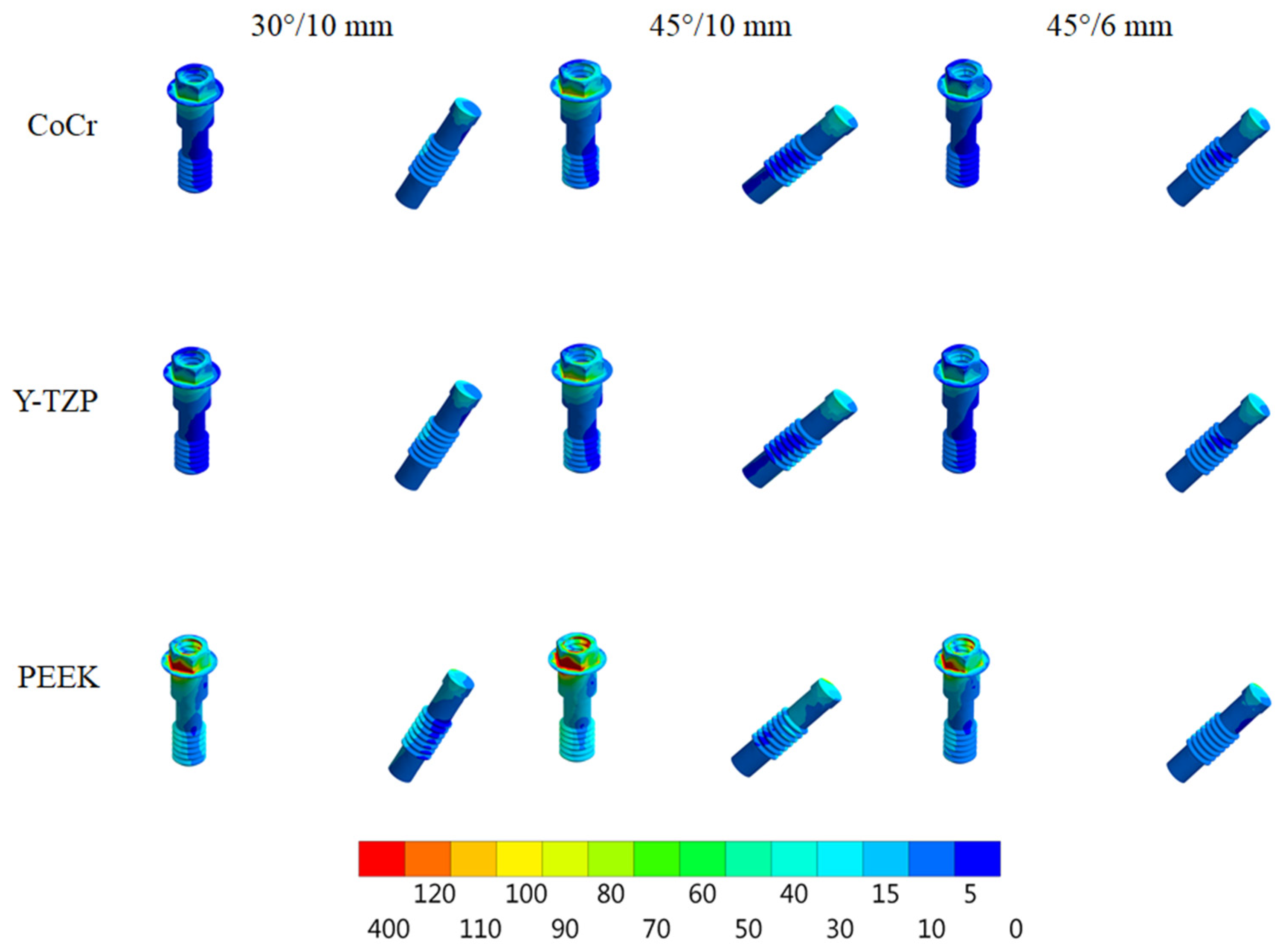
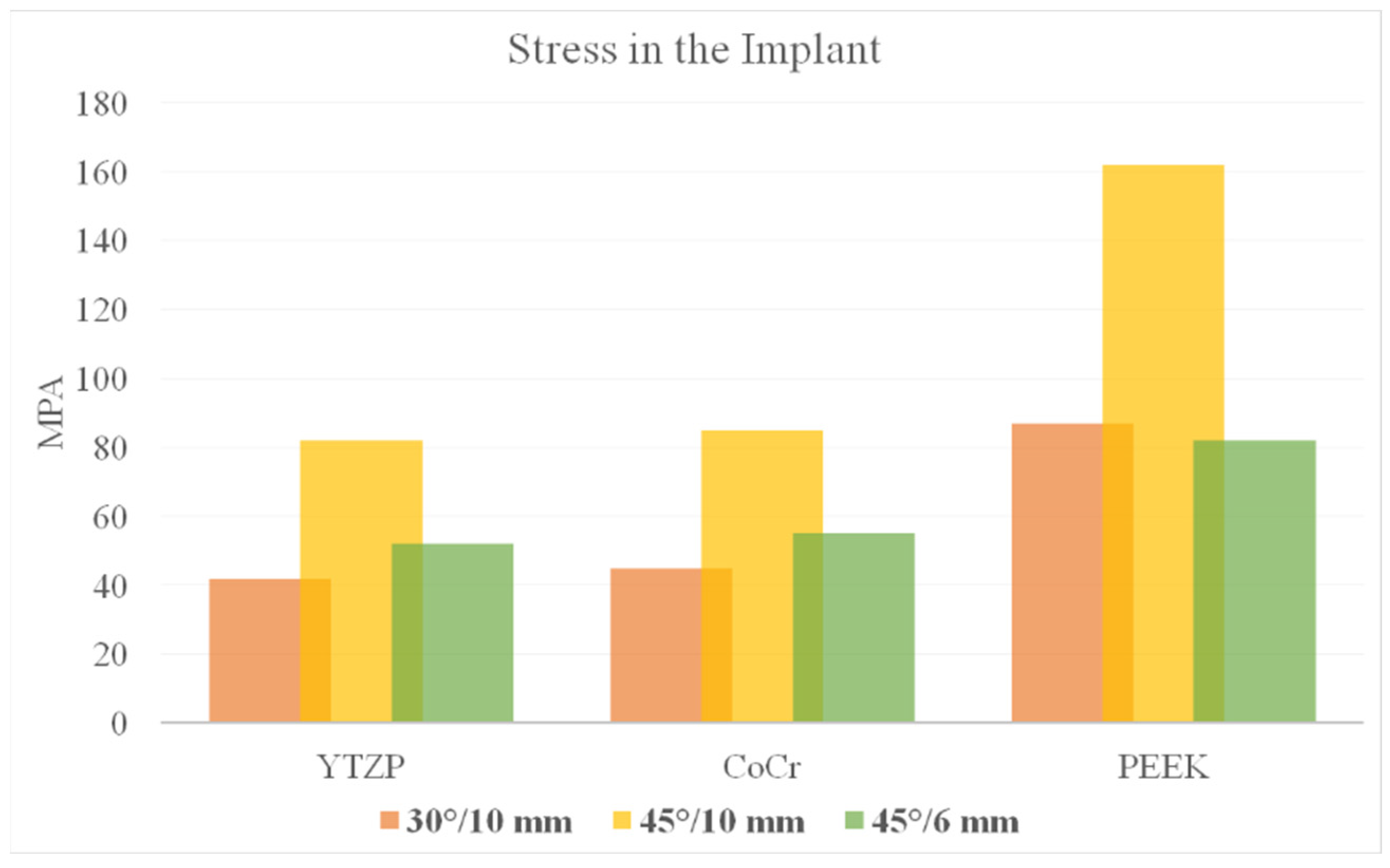
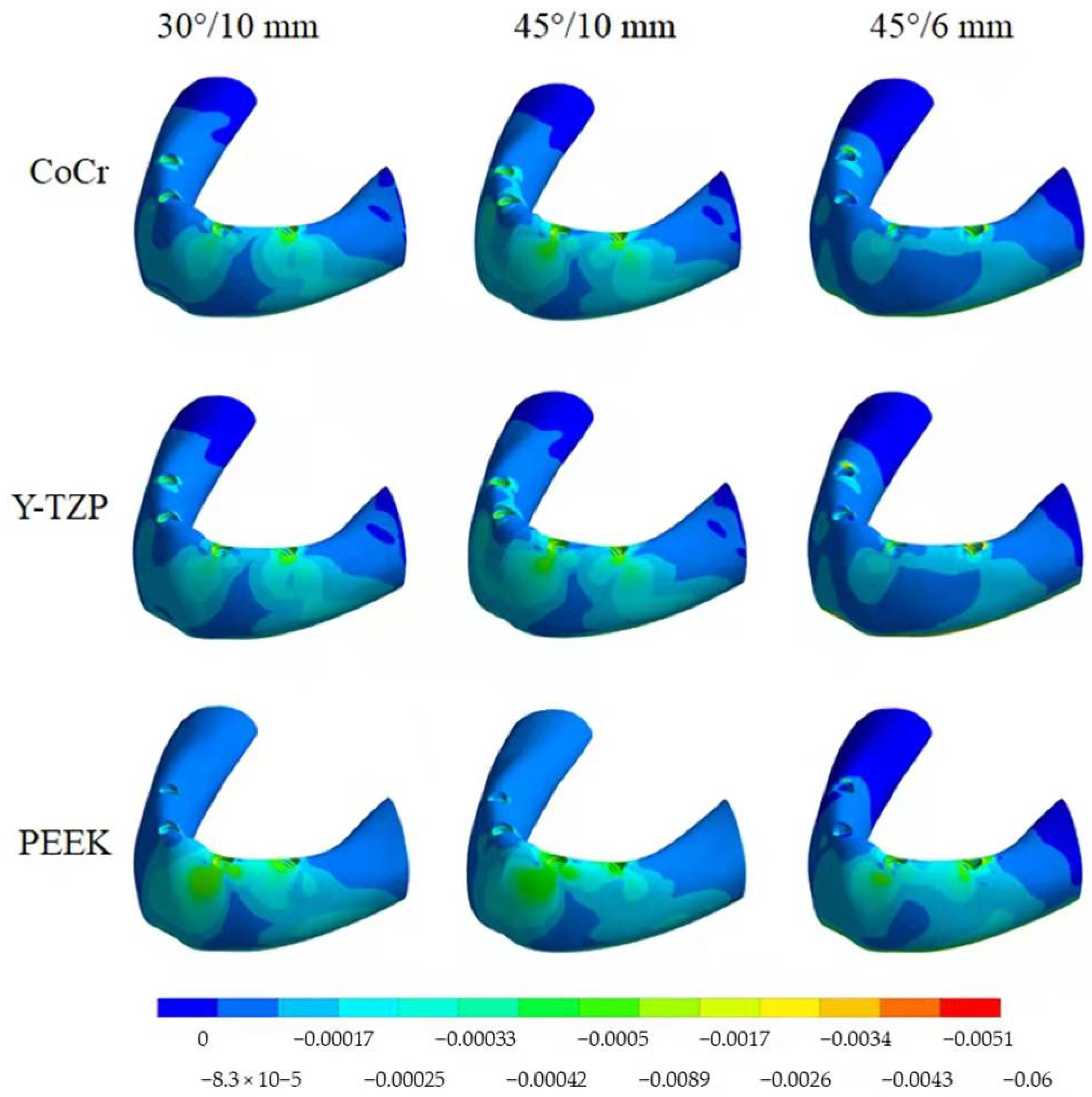
A virtual model of a jaw without maxillofacial abnormalities was exported in DICOM format from the São Paulo State University database. The DICOM file was converted to STL (stereolithography) file in a 3D slicer software. Using the CAD software (Rhinoceros Version 4.0 SR8, McNeel North America, Seattle, WA, USA), a model of an edentulous jaw was created following the main anatomical characteristics of an adult bone: size, shape and absence of pathology [27]. The BioCad method was applied to create a volumetric and solid model [33]. For that, the anatomical surface of the jaw has been delimited by polylines, and the intersection of three or four polylines has been used to form a network surface. The association of juxtaposed and joined surfaces formed the final volume of the 3D model. In sequence, external hexagon implants (10 × 4.1 mm) were created with the external thread diameter being established according to the dimensions provided by the manufacturer (Conexão Sistemas de Prótese, Arujá, Brazil) [18]. The platform had a diameter of 4.1 mm, and the external hexagon presented 0.7 mm of height. The minimum distance between the implants was 4 mm [18,20].
Three different models were created according to distal implant positioning in relation with the implant’s long-axis: 30° with a 10-mm cantilever (30°/10 mm), 45° with a 10-mm cantilever (45°/10 mm) or 45° with a 6-mm cantilever (45°/6 mm).
In this study, the 30° angled implant was considered as a starting point for the All-on-4 technique. Normally, the an All-on-4 concept is performed with two posterior inclined implants. However, implant inclination should be carefully considered during the treatment plan, because it is possible to incline the implant apex or the implant platform to achieve 45° of inclination. The first situation (apex) will keep the cantilever arm similar to the starting point (30°), increasing only the angle of insertion, while the second situation (platform) can reduce the cantilever arm at 40%. For all simulated models, the framework bar that received the load presented the same extension (In Figure 1, the load region in F is similar regardless the model). For that reason, we did not consider 30° with the cantilever of 6 mm, as it would represent a reduction in the extension of the bar and, therefore, a different quantity in the number of teeth.
The framework presented a height of 6 mm from the bone surface and the lever arm following the implant platform position. The screw access holes were created to simulate a clinical situation. Finally, at the end of the framework, a 2-mm diameter delimitation was created to standardize load application [29,33]. The 3D prosthetic screw was modeled for each implant. The geometry designs are presented in Figure 1.
Each solid geometry was imported to the finite element software (ANSYS 17.2, ANSYS Inc., Houston, TX, USA) in STEP format. A 3D mesh was generated, and tetrahedral elements were used. A convergence test of 10% determined the total number of elements and nodes for each model (Table 1).
Young’s modulus and Poisson ratio of each material were assigned to each solid component with isotropic and homogeneous behavior (Table 2).
The jaw model was fixed in all directions on the bottom surfaces, and the contacts were considered bonded. On the delimited distal area (2 mm), a load of 200 N was applied normal to the surface [29,33] (Figure 1). Results were selected in von Mises stress for the framework, implants and prosthetic screw. The maximum (tensile) and minimum (compression) principal stresses criteria were evaluated for bone tissue.

3. Results

According to Von Mises stress results in the framework, the lower the material elastic modulus, the lower the stress concentration. In addition, the 45°/6 mm position showed the lowest stress peak values (Figure 2 and Figure 3). The opposite was observed for the prosthetic screw (Figure 4 and Figure 5) and implants (Figure 6 and Figure 7): The lower the framework elastic modulus, the higher the stress concentration. Moreover, the same implant position (45°/6 mm) showed highest peak values in these structures. The use of PEEK framework associated with 45°/10 mm design showed the highest stress magnitude in the screw and in the implants. Regardless the framework material and design, the highest stress concentration was calculated in the first thread for the prosthetic screw in the mesial implants. The maximum principal and minimum principal stresses peaks were plotted in the bar graphs. Stress peaks have been collected using the auto-tool max probe in mechanical APDL software after processing the results. Regardless of stress magnitude, the stress distribution trend was similar between the models, with the highest stress in the prosthetic screw head and implant platform.
The highest σMAX magnitude was calculated in the mesial implants in the cervical buccal region (Figure 8 and Figure 9), while σMIN peaks were concentrated in the cervical area of the distal implant (Figure 10 and Figure 11). Regarding bone stress, the framework in PEEK resulted in lower σMAX and higher the σMIN in bones. The 45°/10 mm position showed the highest concentration for both criteria, while the 45°/6 mm position resulted in the lowest stress concentration. The 30°/10 mm position showed intermediate behavior, suggesting that higher implant angulation should only be used if the cantilever can be reduced with it.

4. Discussion

The present study evaluated the stress distribution in All-on-4 prosthesis regarding framework material and posterior implant angulation. The results showed that both factors affected the mechanical response during a vertical load simulation. Thus, the hypothesis was rejected.
According to the literature [33,34], the vertical load in the molar region can vary from 150 to 800 N, and there is a reduction of 30% to 40% in terms of the amount of load when applied unilaterally compared to bilateral applications [35]. In this study, load was applied with 200 N reported as the mean value of occlusal force in the posterior region in implant-supported prosthesis [29,36].
A previous report [37] performed a 3D-finite element model of an edentulous jaw, and a vertical load of 200N was applied at the cantilever similar to the present study. The authors affirmed that the framework material (metal or acrylic resin) did not play an important role in reducing peri-implant bone strain and that a reduced cantilever improved the mechanical response. The present study is in agreement with the benefits provided by a short cantilever arm; however, the results presented herein suggest that a flexible framework seems to be able to increase peri-implant stress (Figure 2 and Figure 3).
Regarding the framework elastic modulus, a previous study [38] found that PEEK framework showed highest stress peaks in comparison with more rigid materials for the prosthetic screw. The present study corroborates with this finding (Figure 4 and Figure 5) and agrees that further studies are necessary for evaluating screw performance. A prospective cohort clinical study with 37 patients analyzed the short-term outcome of full-arch implant-supported fixed hybrid PEEK prostheses in the All-on-4 concept [39]. The authors suggest that PEEK resin prostheses for full-arch rehabilitation may represent a valid treatment option. The authors also reported that five prostheses presented prosthetic screw loosening. This can be explained with the increased stress concentration in the screw, as showed in the present study’s results.
Higher stress magnitude was observed in the mesial screws, agreeing with other studies [10,17,18,20] and showing similarity to the result found in the bone where tensile stress was higher in the region of the mesial implants. This can be justified because it is a more distant position of the cantilever that undergoes movement during the application of load in this region, functioning as a lever system.
In another clinical study [40], the authors performed a three-year prospective evaluation from PEEK framework with the All-on-4 concept. The authors suggest that the proposed rehabilitation solution is a legitimate treatment option. From thirty-seven patients, three patients presented screw loosening and one patient presented peri-implant pathology solved with surgery. These complications can be associated with the use of a flexible framework able to bend during chewing and able to stress the screw and bone, as shown in the present study. However, this is only one hypothesis from what could occur.
The prosthesis was designed by varying the length of the cantilever, since the 45° angulation of the distal implants would change its extension. Indeed, the 45° implant and reduced cantilever (45°/6 mm) showed less stress magnitude (Figure 6 and Figure 7) corroborating with previous studies that verified a direct relationship between the length of the cantilever and stress concentration [7,8,9,10,11]. However, if the cantilever length was not reduced and implant angulation increases (45°/10 mm), the stress concentration will increase in comparison with the 30° angulation group.
With photo-elastic strain analysis, a previous study [41] found that metal and zirconia showed strain patterns lower than PEEK with the All-on-4 concept. The authors justify these results by asserting that an increased elastic modulus of the framework reduced the stresses transmitted to the implants and bone. The present study is in agreement with this statement since a similar mechanical behavior for the implants and bone (Figure 8, Figure 9, Figure 10 and Figure 11) was observed with similar materials and model design.
Bone behavior was evaluated in tensile (σMAX) and compression (σMIN) stresses [42,43,44]. In compression, the highest magnitude was found near the cervical area of the distal implant near of the load application site (distal cantilever region) (Figure 10). Therefore, the distal implant suffered more compression, and the mesial implant showed the highest tensile stress (Figure 8), a behavior that is in agreement with the results of previous studies [10,43,44,45]. In this case, the framework material that transferred more stress to the bone in both compression and tensile stress was PEEK (Figure 9 and Figure 11).
The influence of posterior implant angulations has already been reported in the literature [46]. By using 3D finite element analysis (3D-FEA), a previous study affirmed that stress increased when implants increased in angulation; however, when used with a short cantilever, inclined implants decreased stress on peri-implant cortical bone. The present study corroborates with these results, showing the same mechanical behavior for the 45° with the 6-mm model.
The literature presents a higher survival rate (90%) for implant-supported full-arch prosthesis with longer cantilevers (7–12 mm) after 15 years of clinical follow-up [2]. Thus, the use of cantilever is a clinical option that can be used in some cases of rehabilitation, resulting in clinical success in the long term but at the same time depends on correct planning and biomechanics understating.
Despite dental PEEK presenting a wide clinical indication, such as fixed dental prostheses [47], removable partial dentures [48] and implant-supported frameworks [49], its use should be applied with caution due to the increase in stress contraction in prone-to-failure regions, e.g., prosthetic screws. In addition, further studies can be carried out evaluating the interaction between resinous cement and polymeric structures for cement-retained frameworks, focusing on polymerization shrinkage Kinects [50,51].
A previous study aimed to analyze the effects of different materials used for framework fabrication on the “All-on-4” implant system by using the finite element method. The authors considered three framework materials (Titanium, Zirconia and PEEK) in the study for the evaluation of stresses in peri-implant regions [52]. According to their simulation, the stress distribution pattern at the implant–bone interface was influenced by the framework material used while a zirconia framework showed minimal stress magnitude. In addition, the length of cantilever increased stress concentrations regardless the framework materials [52]. Therefore, the present study corroborates with that result by showing an increased stress trend with higher cantilever arm (10 mm) in comparison with reduced one (6 mm).
According to the literature [53], increasing the inclination in posterior implants resulted in a reduction in cantilever length and maximum stress decline in both cancellous and cortical bone. The effect of cantilever length seems to be a dominant factor for the stress magnitude [53]. Therefore, the present study corroborates with this statement by showing that reduced cantilever length using a higher inclination for the implant’s placement can be beneficial. In addition, the cantilever length should be measured from the most posterior implant platform, confirming that the inclination of the implant platform was done instead of the implant apex.
Applying the current advances in dental implants associated with the All-on-4 treatment concept generally reduces treatment time, risk of morbidity and other possible risks in the edentulous patient [54]. In order to prove this, a previous 3D-FEA study showed that the use of implant-supported ceramic prosthesis as an antagonist to another implant-supported full arch prosthesis increases the amount of stresses transmitted to the bone and that there is no difference in the amount of stresses when comparing natural tooth to tooth-supported ceramic restorations as an antagonist [54]. The authors affirmed that the model design followed the classic All-on-4 configuration by tilting posterior implants to a 30° angle, but changing the angle or the configuration of the implants could result in different results from a biomechanical standpoint [54]. The present study demonstrates that this hypothesis is correct; indeed, posterior implant inclination can affect the entire system mechanical responses.
The use of in vitro investigations also can be used to describe mechanical responses. A previous investigation [55] applied linear strain gauges to measure the strain during compressive loading in full-arch rehabilitations. According to the results, the amount of peri-implant strain in All-on-4 implant-supported prosthesis depends on the selection of framework material, cantilever length and the occlusal forces from the opposing arch. In addition, when mandibular All-on-4 implant-supported prostheses are placed opposite to parafunctional forces, the presence of the cantilever might result in peri-implant strain generation beyond the physiological limits of bones, irrespective of the type of framework material [55]. For that reason, reducing the cantilever size can be a promising approach during the treatment plan.
The present study considered only unilateral loading conditions, showing asymmetric stress distribution between model extensions. The use of posterior loading with bilateral occlusion could modify the results and stress magnitude; however, the difference in the groups could possibly be proportional to the present condition, as previously demonstrated [56,57]. Another variable that was not evaluated in the present study is the different implant connections [58,59,60,61]. The use of an external hexagon implant system can present a different mechanical response from internal connection systems, e.g., internal hexagon and Morse-taper, affecting peri-implant tissue stability and prognosis [58,59,60,61]. Therefore, new stress analyses should be performed by considering these variables during the modelling step, which aims to corroborate the present study results.
The method of 3D-FEA has been widely used to simulate clinical situations and provide scientific data. However, it is relevant to mention that this study did not simulate the dynamic medium that is the human mouth. Thus, humidity, chewing, pH and temperature variations and other bone conditions should be evaluated in further investigations to corroborate with the present findings.

5. Conclusions

For the All-on-4 technique, an angulation of 45° for distal implants is only beneficial if it is possible to reduce the cantilever’s length. Otherwise, 30° should be considered as the first choice. In addition, stiffer framework materials concentrated more stress in its structure, reducing prosthetic screw stress magnitude.

Author Contributions

Conceptualization, J.P.M.T., D.C.d.M., A.M.d.O.D.P., A.L.S.B., M.A.B., A.L., M.M. and P.A.; methodology, J.P.M.T., A.M.d.O.D.P., A.L.S.B., A.L. and P.A.; software, A.L.S.B., M.A.B. and P.A.; validation, J.D.M.d.M., G.d.R.S.L. and M.M.; formal analysis, J.P.M.T., A.M.d.O.D.P., A.L.S.B., A.L., M.M. and P.A.; investigation, J.P.M.T., D.C.d.M., J.D.M.d.M., A.M.d.O.D.P., A.L.S.B., A.L., M.M. and P.A.; resources, A.L.S.B., M.A.B., A.L., M.M. and P.A.; data curation, D.C.d.M., J.D.M.d.M. and G.d.R.S.L.; writing—original draft preparation, J.P.M.T., D.C.d.M., A.L.S.B., M.A.B. and A.L.; writing—review and editing, J.P.M.T., A.M.d.O.D.P., M.M. and P.A.; visualization, J.P.M.T., D.C.d.M., A.L.S.B. and P.A.; supervision, J.P.M.T., A.L.S.B., M.A.B., A.L., M.M. and P.A.; project administration, A.M.d.O.D.P., G.d.R.S.L. and P.A.; funding acquisition, J.P.M.T., A.L.S.B., A.L., M.M. and P.A. All authors have read and agreed to the published version of the manuscript.

Funding

This research received no external funding.

Institutional Review Board Statement

Not applicable.

Informed Consent Statement

Not applicable.

Data Availability Statement

Data available upon request.

Conflicts of Interest

The authors declare no conflict of interest.

References

  1. Astrand, P.; Ahlqvist, J.; Gunne, J.; Nilson, H. Implant treatment of patients with edentulous jaws: A 20-year follow-up. Clin. Implant Dent. Relat. Res. 2008, 10, 207–217. [Google Scholar] [CrossRef]
  2. Jemt, T.; Johansson, J. Implant treatment in the edentulous maxillae: A 15-year follow-up study on 76 consecutive patients provided with fixed prostheses. Clin. Implant Dent. Relat. Res. 2006, 8, 61–69. [Google Scholar] [CrossRef]
  3. Irandoust, S.; Müftü, S. The interplay between bone healing and remodeling around dental implants. Sci. Rep. 2020, 10, 4335. [Google Scholar] [CrossRef] [Green Version]
  4. Gomes, L.C.L.; Pierre, F.Z.; Tribst, J.P.M.; Ramos, N.D.C.; Bresciani, E.; de Araújo, R.M.; Júnior, L.N.; Bottino, M.A. Occlusal scheme effect on the biomechanical response of full-arch dental prosthesis supported by titanium implants: A systematic review. Metals 2021, 11, 1574. [Google Scholar] [CrossRef]
  5. Jivraj, S.; Chee, W. Treatment planning of implants in posterior quadrants. Br. Dent. J. 2006, 201, 13–23. [Google Scholar] [CrossRef] [Green Version]
  6. Maló, P.; de Araújo Nobre, M.; Lopes, A.; Ferro, A.; Gravito, I. All-on-4® treatment concept for the rehabilitation of the completely edentulous mandible: A 7-year clinical and 5-year radiographic retrospective case series with risk assessment for implant failure and marginal bone level: Complete edentulous mandible rehabilitation. Clin. Implant Dent. Relat. Res. 2015, 17, e531–e541. [Google Scholar]
  7. Bevilacqua, M.; Tealdo, T.; Menini, M.; Pera, F.; Mossolov, A.; Drago, C.; Pera, P. The influence of cantilever length and implant inclination on stress distribution in maxillary implant-supported fixed dentures. J. Prosthet. Dent. 2011, 105, 5–13. [Google Scholar] [CrossRef]
  8. Capparé, P.; Teté, G.; Romanos, G.E.; Nagni, M.; Sannino, G.; Gherlone, E.F. The “All-on-four” protocol in HIV-positive patients: A prospective, longitudinal 7-year clinical study. Int. J. Oral Implantol. 2019, 12, 501–510. [Google Scholar]
  9. Durkan, R.; Oyar, P.; Deste, G. Maxillary and mandibular all-on-four implant designs: A review. Niger. J. Clin. Pract. 2019, 22, 1033–1040. [Google Scholar] [PubMed]
  10. Rubo, J.H.; Souza, E.A.C. Finite element analysis of stress in bone adjacent to dental implants. J. Oral Implantol. 2008, 34, 248–255. [Google Scholar]
  11. Türker, N.; Büyükkaplan, U.S.; Sadowsky, S.J.; Özarslan, M.M. Finite element stress analysis of applied forces to implants and supporting tissues using the “all-on-Four” concept with different occlusal schemes. J. Prosthodont. 2019, 28, 185–194. [Google Scholar] [CrossRef]
  12. Agliardi, E.; Clericò, M.; Ciancio, P.; Massironi, D. Immediate loading of full-arch fixed prostheses supported by axial and tilted implants for the treatment of edentulous atrophic mandibles. Quintessence Int. 2010, 41, 285–293. [Google Scholar]
  13. Agliardi, E.; Panigatti, S.; Clericò, M.; Villa, C.; Malò, P. Immediate rehabilitation of the edentulous jaws with full fixed prostheses supported by four implants: Interim results of a single cohort prospective study. Clin. Oral Implants Res. 2010, 21, 459–465. [Google Scholar] [CrossRef] [PubMed]
  14. Francetti, L.; Agliardi, E.; Testori, T.; Romeo, D.; Taschieri, S.; Del Fabbro, M. Immediate rehabilitation of the mandible with fixed full prosthesis supported by axial and tilted implants: Interim results of a single cohort prospective study. Clin. Implant Dent. Relat. Res. 2008, 10, 255–263. [Google Scholar] [CrossRef]
  15. Crespi, R.; Vinci, R.; Capparé, P.; Romanos, G.E.; Gherlone, E. A clinical study of edentulous patients rehabilitated according to the “all on four” immediate function protocol. Int. J. Oral Maxillofac. Implant. 2012, 27, 428–434. [Google Scholar]
  16. Liu, T.; Mu, Z.; Yu, T.; Wang, C.; Huang, Y. Biomechanical comparison of implant inclinations and load times with the all-on-4 treatment concept: A three-dimensional finite element analysis. Comput. Methods Biomech. Biomed. Eng. 2019, 22, 585–594. [Google Scholar] [CrossRef]
  17. Wu, A.Y.-J.; Hsu, J.-T.; Fuh, L.-J.; Huang, H.-L. Effects of positions and angulations of titanium dental implants in biomechanical performances in the all-on-four treatment: 3D numerical and strain gauge methods. Metals 2020, 10, 280. [Google Scholar] [CrossRef] [Green Version]
  18. Tribst, J.P.M.; Dal Piva, A.M.D.O.; Lo Giudice, R.; Borges, A.L.S.; Bottino, M.A.; Epifania, E.; Ausiello, P. The influence of custom-milled framework design for an implant-supported full-arch fixed dental prosthesis: 3D-FEA sudy. Int. J. Environ. Res. Public Health 2020, 17, 4040. [Google Scholar] [CrossRef]
  19. Gonzalez, J. The evolution of dental materials for hybrid prosthesis. Open Dent. J. 2014, 8, 85–94. [Google Scholar] [CrossRef] [Green Version]
  20. Tribst, J.P.M.; Dal Piva, A.M.D.O.; Borges, A.L.S.; Rodrigues, V.A.; Bottino, M.A.; Kleverlaan, C.J. Does the prosthesis weight matter? 3D finite element analysis of a fixed implant-supported prosthesis at different weights and implant numbers. J. Adv. Prosthodont. 2020, 12, 67–74. [Google Scholar] [CrossRef] [Green Version]
  21. Ashkanani, H.M.; Raigrodski, A.J.; Flinn, B.D.; Heindl, H.; Mancl, L.A. Flexural and shear strengths of ZrO2 and a high-noble alloy bonded to their corresponding porcelains. J. Prosthet. Dent. 2008, 100, 274–284. [Google Scholar] [CrossRef]
  22. Sailer, I.; Gottnerb, J.; Kanelb, S.; Hammerle, C.H.F. Randomized controlled clinical trial of zirconia-ceramic and metal-ceramic posterior fixed dental prostheses: A 3-year follow-up. Int. J. Prosthodont. 2009, 22, 553–560. [Google Scholar]
  23. Takaba, M.; Tanaka, S.; Ishiura, Y.; Baba, K. Implant-supported fixed dental prostheses with CAD/CAM-fabricated porcelain crown and zirconia-based framework: CAD/CAM porcelain crowns and Zirconia framework. J. Prosthodont. 2013, 22, 402–407. [Google Scholar] [CrossRef]
  24. Pokorný, D.; Fulín, P.; Slouf, M.; Jahoda, D.; Landor, I.; Sosna, A. Polyetheretherketone (PEEK). Part II: Application in clinical practice. Acta Chir. Orthop. Traumatol. Cech. 2010, 77, 470–478. [Google Scholar]
  25. Papathanasiou, I.; Kamposiora, P.; Papavasiliou, G.; Ferrari, M. The use of PEEK in digital prosthodontics: A narrative review. BMC Oral Health 2020, 20, 217. [Google Scholar] [CrossRef]
  26. Dal Piva, A.M.D.O.; Tribst, J.P.M.; Borges, A.L.S.; Souza, R.O.d.A.e.; Bottino, M.A. CAD-FEA modeling and analysis of different full crown monolithic restorations. Dent. Mater. 2018, 34, 1342–1350. [Google Scholar] [CrossRef] [Green Version]
  27. Tribst, J.P.M.; Dal Piva, A.M.D.O.; Bottino, M.A.; Kleverlaan, C.J.; Koolstra, J.H. Mouthguard use and TMJ injury prevention with different occlusions: A three-dimensional finite element analysis. Dent. Traumatol. 2020, 36, 662–669. [Google Scholar] [CrossRef]
  28. Idogava, H.T.; Noritomi, P.Y.; Daniel, G.B. Numerical model proposed for a temporomandibular joint prosthesis based on the recovery of the healthy movement. Comput. Methods Biomech. Biomed. Eng. 2018, 21, 503–511. [Google Scholar] [CrossRef]
  29. Dal Piva, A.M.D.O.; Tribst, J.M.; de Morais, D.; Alonso, A.; Borges, A.S. Comparative three-dimensional finite element analysis of implant-supported fixed complete arch mandibular prostheses in two materials. J. Indian Prosthodont. Soc. 2017, 17, 255. [Google Scholar] [CrossRef]
  30. Penteado, M.M.; Tribst, J.P.M.; Dal Piva, A.M.; Ausiello, P.; Zarone, F.; Garcia-Godoy, F.; Borges, A.L. Mechanical behavior of conceptual posterior dental crowns with functional elasticity gradient. Am. J. Dent. 2019, 32, 165–168. [Google Scholar]
  31. Ausiello, P.; Ciaramella, S.; Di Rienzo, A.; Lanzotti, A.; Ventre, M.; Watts, D.C. Adhesive class I restorations in sound molar teeth incorporating combined resin-composite and glass ionomer materials: CAD-FE modeling and analysis. Dent. Mater. 2019, 35, 1514–1522. [Google Scholar] [CrossRef]
  32. Martorelli, M.; Ausiello, P. A novel approach for a complete 3D tooth reconstruction using only 3D crown data. Int. J. Interact. Des. Manuf. (IJIDeM) 2013, 7, 125–133. [Google Scholar] [CrossRef]
  33. Bonfante, E.A.; Coelho, P.G. A critical perspective on mechanical testing of implants and prostheses. Adv. Dent. Res. 2016, 28, 18–27. [Google Scholar] [CrossRef]
  34. DeLong, R.; Douglas, W.H. Development of an artificial oral environment for the testing of dental restoratives: Bi-axial force and movement control. J. Dent. Res. 1983, 62, 32–36. [Google Scholar] [CrossRef]
  35. Ausiello, P.; Tribst, J.P.M.; Ventre, M.; Salvati, E.; di Lauro, A.E.; Martorelli, M.; Lanzotti, A.; Watts, D.C. The role of cortical zone level and prosthetic platform angle in dental implant mechanical response: A 3D finite element analysis. Dent. Mater. 2021, 37, 1688–1697. [Google Scholar] [CrossRef]
  36. Mericske-Stern, R.; Assal, P.; Mericske, E.; Ing, W.B. Occlusal force and oral tactile sensibility measured in partially edentulous patients with ITI implants. Implant Dent. 1996, 5, 59. [Google Scholar] [CrossRef]
  37. Horita, S.; Sugiura, T.; Yamamoto, K.; Murakami, K.; Kirita, T. Biomechanical analysis of immediately loaded implants according to the all-on-four concept. Int. J. Oral Maxillofac. Surg. 2017, 46, 268. [Google Scholar] [CrossRef] [Green Version]
  38. Villefort, R.F.; Tribst, J.P.M.; Dal Piva, A.M.D.O.; Borges, A.L.; Binda, N.C.; Ferreira, C.E.d.A.; Bottino, M.A.; von Zeidler, S.L.V. Stress distribution on different bar materials in implant-retained palatal obturator. PLoS ONE 2020, 15, e0241589. [Google Scholar] [CrossRef]
  39. Maló, P.; de Araújo Nobre, M.; Moura Guedes, C.; Almeida, R.; Silva, A.; Sereno, N.; Legatheaux, J. Short-term report of an ongoing prospective cohort study evaluating the outcome of full-arch implant-supported fixed hybrid polyetheretherketone-acrylic resin prostheses and the All-on-Four concept. Clin. Implant Dent. Relat. Res. 2018, 20, 692–702. [Google Scholar] [CrossRef]
  40. De Araújo Nobre, M.; Moura Guedes, C.; Almeida, R.; Silva, A.; Sereno, N. Hybrid polyetheretherketone (PEEK)-acrylic resin prostheses and the all-on-4 concept: A full-arch implant-supported fixed solution with 3 years of follow-up. J. Clin. Med. 2020, 9, 2187. [Google Scholar] [CrossRef]
  41. Çalışkan, A.; Yöndem, İ. Stress Analysis Of Fixed Dental Prostheses Produced With Different Materials According To The All-On-Four Concept. J. Biotechnol. Strateg. Health Res. 2019, 3, 183–191. [Google Scholar] [CrossRef]
  42. Bankoğlu Güngör, M.; Yılmaz, H. Evaluation of stress distributions occurring on zirconia and titanium implant-supported prostheses: A three-dimensional finite element analysis. J. Prosthet. Dent. 2016, 116, 346–355. [Google Scholar] [CrossRef]
  43. Bellini, C.M.; Romeo, D.; Galbusera, F.; Taschieri, S.; Raimondi, M.T.; Zampelis, A.; Francetti, L. Comparison of tilted versus nontilted implant-supported prosthetic designs for the restoration of the edentuous mandible: A biomechanical study. Int. J. Oral Maxillofac. Implant. 2009, 24, 511–517. [Google Scholar]
  44. Bhering, C.L.B.; Mesquita, M.F.; Kemmoku, D.T.; Noritomi, P.Y.; Consani, R.L.X.; Barão, V.A.R. Comparison between all-on-four and all-on-six treatment concepts and framework material on stress distribution in atrophic maxilla: A prototyping guided 3D-FEA study. Mater. Sci. Eng. C Mater. Biol. Appl. 2016, 69, 715–725. [Google Scholar] [CrossRef]
  45. Tashkandi, E.A.; Lang, B.R.; Edge, M.J. Analysis of strain at selected bone sites of a cantilevered implant-supported prosthesis. J. Prosthet. Dent. 1996, 76, 158–164. [Google Scholar] [CrossRef]
  46. Takahashi, T.; Shimamura, I.; Sakurai, K. Influence of number and inclination angle of implants on stress distribution in mandibular cortical bone with All-on-4 Concept. J. Prosthodont. Res. 2010, 54, 179–184. [Google Scholar] [CrossRef]
  47. Campaner, L.M.; Silveira, M.P.M.; de Andrade, G.S.; Borges, A.L.S.; Bottino, M.A.; Dal Piva, A.M.D.O.; Lo Giudice, R.; Ausiello, P.; Tribst, J.P.M. Influence of polymeric restorative materials on the stress distribution in posterior fixed partial dentures: 3D finite element analysis. Polymers 2021, 13, 758. [Google Scholar] [CrossRef] [PubMed]
  48. Tribst, J.P.M.; Dal Piva, A.M.D.O.; Borges, A.L.S.; Araújo, R.M.; da Silva, J.M.F.; Bottino, M.A.; Kleverlaan, C.J.; de Jager, N. Effect of different materials and undercut on the removal force and stress distribution in circumferential clasps during direct retainer action in removable partial dentures. Dent. Mater. 2020, 36, 179–186. [Google Scholar] [CrossRef] [PubMed]
  49. Villefort, R.F.; Diamantino, P.J.S.; von Zeidler, S.L.V.; Borges, A.L.S.; Silva-Concílio, L.R.; Saavedra, G.D.S.F.A.; Tribst, J.P.M. Mechanical response of PEKK and PEEK as frameworks for implant-supported full-arch fixed dental prosthesis: 3D finite element analysis. Eur. J. Dent. 2021. [Google Scholar] [CrossRef] [PubMed]
  50. Treglia, A.S.; Turco, S.; Ulianich, L.; Ausiello, P.; Lofrumento, D.D.; Nicolardi, G.; Miele, C.; Garbi, C.; Beguinot, F.; Di Jeso, B. Cell fate following ER stress: Just a matter of “quo ante” recovery or death? Histol. Histopathol. 2012, 27, 1–12. [Google Scholar]
  51. Apicella, A.; Di Palma, L.; Aversa, R.; Ausiello, P. DSC kinetic characterization of dental composites using different light sources. J. Adv. Mater. 2002, 34, 22–25. [Google Scholar]
  52. Kelkar, K.C.; Bhat, V.; Hegde, C. Finite element analysis of the effect of framework materials at the bone-implant interface in the all-on-four implant system. Dent. Res. J. 2021, 18, 1. [Google Scholar]
  53. Saleh Saber, F.; Ghasemi, S.; Koodaryan, R.; Babaloo, A.; Abolfazli, N. The comparison of stress distribution with different implant numbers and inclination angles in all-on-four and conventional methods in maxilla: A finite element analysis. J. Dent. Res. Dent. Clin. Dent. Prospects 2015, 9, 246–253. [Google Scholar] [CrossRef]
  54. Haroun, F.; Ozan, O. Evaluation of stresses on implant, bone, and restorative materials caused by different opposing arch materials in hybrid prosthetic restorations using the All-on-4 technique. Materials 2021, 14, 4308. [Google Scholar] [CrossRef]
  55. Shetty, R.; Singh, I.; Sumayli, H.A.; Jafer, M.A.; Abdul Feroz, S.M.; Bhandi, S.; Raj, A.T.; Patil, S.; Ferrari, M. Effect of prosthetic framework material, cantilever length and opposing arch on peri-implant strain in an all-on-four implant prostheses. Niger. J. Clin. Pract. 2021, 24, 866–873. [Google Scholar]
  56. Ebadian, B.; Farzin, M.; Talebi, S.; Khodaeian, N. Evaluation of stress distribution of implant-retained mandibular overdenture with different vertical restorative spaces: A finite element analysis. Dent. Res. J. 2012, 9, 741–747. [Google Scholar]
  57. Malhotra, A.O.; Padmanabhan, T.V.; Mohamed, K.; Natarajan, S.; Elavia, U. Load transfer in tilted implants with varying cantilever lengths in an all-on-four situation: Load transfer in an all-on-four situation. Aust. Dent. J. 2012, 57, 440–445. [Google Scholar] [CrossRef]
  58. Refaie, A.; Zohdy, M.; Aboelfadl, A.; Wahsh, M. Effect of different immediate implant loading protocols on Peri-implant soft tissue health. Braz. Dent. Sci. 2020, 23, 7. [Google Scholar] [CrossRef]
  59. Tribst, J.P.M.; Dal Piva, A.M.D.O.; Rodrigues, V.A.; Borges, A.L.S.; Nishioka, R.S. Stress and strain distributions on short implants with two different prosthetic connections—An in vitro and in silico analysis. Braz. Dent. Sci. 2017, 20, 101–109. [Google Scholar] [CrossRef] [Green Version]
  60. Ceruso, F.M.; Ieria, I.; Martelli, M.; Lumbau, A.I.; Xhanari, E.; Gargari, M. New generation of fixture-abutment connection combining soft tissue design and vertical screw-retained restoration: 1-year clinical, aesthetics and radiographic preliminary evaluation. Dent. J. 2021, 9, 35. [Google Scholar] [CrossRef]
  61. Barreiros, P.; Neves, L.; Aroso, C.; Mendes, J.M.; Silva, A.S. Comparison in four different implant systems of mechanical resistance to maximal stress in prosthetic screws-an in vitro study. Dent. J. 2020, 8, 116. [Google Scholar] [CrossRef] [PubMed]
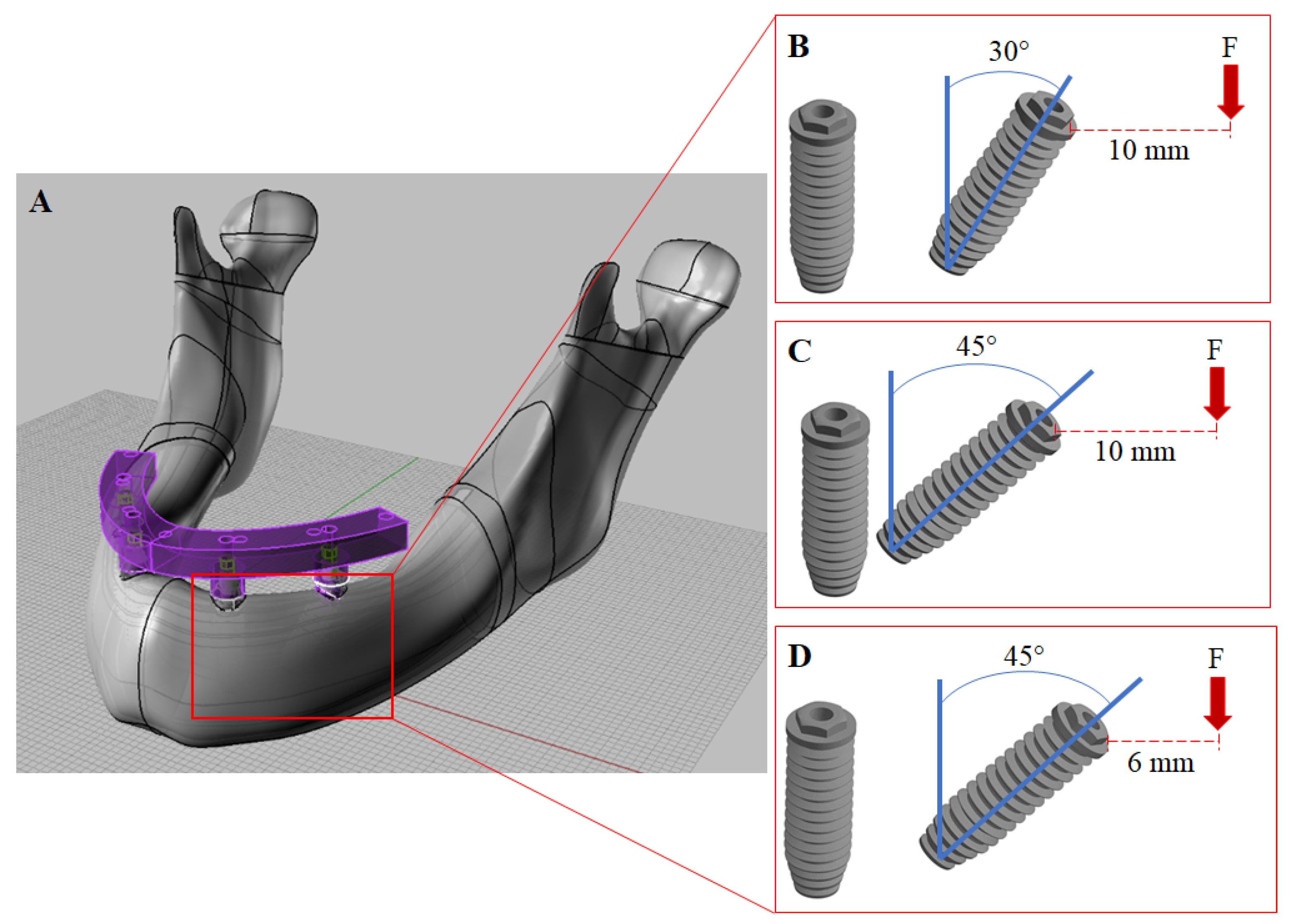
Figure 1. (A) Three-dimensional modeling of an All-on-4 full arch prosthesis in perspective view. (B) Distal implants with 30° angulation and a 10-mm cantilever. (C) Distal implants with 45° angulation and a 10-mm cantilever arm. (D) Distal implants with 45° angulation and a 6-mm cantilever. Read arrows (F) represent where the 200 N load was applied.
Dentistry 10 00012 g001
Figure 2. Von Mises stress in the prosthetic framework according to framework material (CoCr, Y-TZP and PEEK) and distal implant position (30° and 10-mm cantilever, 45° and 10-mm cantilever and 45° and 6-mm cantilever).
Dentistry 10 00012 g002
Figure 3. Bar graph with Von Mises stress peaks in the prosthesis’ framework according to material and distal implants position.
Dentistry 10 00012 g003
Figure 4. Von Mises stress in the prosthetic screws (anterior and posterior) according to framework material (CoCr, Y-TZP and PEEK) and distal implant position (30° and 10-mm cantilever, 45° and 10-mm cantilever and 45° and 6-mm cantilever).
Dentistry 10 00012 g004
Figure 5. Bar graph with Von Mises stress peaks in the prosthetic screw according to material and distal implant position.
Dentistry 10 00012 g005
Figure 6. Von Mises stress in the prosthetic implants (anterior and posterior) according to framework material (CoCr, Y-TZP and PEEK) and distal implant position (30° and 10-mm cantilever, 45° and 10-mm cantilever and 45° and 6-mm cantilever).
Dentistry 10 00012 g006
Figure 7. Bar graph with Von Mises stress peaks in the implant according to material and distal implant position.
Dentistry 10 00012 g007
Figure 8. Tensile stress (σMAX) in the bone according to material (CoCr, Y-TZP and PEEK) and distal implant position (30° and 10-mm cantilever, 45° and 10-mm cantilever and 45° and 6-mm cantilever).
Dentistry 10 00012 g008
Figure 9. Bar graph with Tensile (σMAX) stress peaks in the bone according to material and distal implant position.
Dentistry 10 00012 g009
Figure 10. Compressive stress (σMIN) in the bone according to material (CoCr, Y-TZP and PEEK) and distal implant position (30° and 10-mm cantilever, 45° and 10-mm cantilever and 45° and 6-mm cantilever).
Dentistry 10 00012 g010
Figure 11. Bar graph with Compressive (σMIN) stress peaks in the bone according to material and distal implant position.
Dentistry 10 00012 g011
Table 1. Number of nodes and elements used in the analysis for each model.
Inclination of Distal Implants (°)Distal Cantilever (mm)NodesElements
30101.133.298645.591
45101.037.324625.014
4561.084.148597.018
Table 2. Mechanical properties of materials used in finite element analysis.
StructureElastic Modulus (GPa)Poisson Ratio
Cancellous bone1.370.3
Cortical bone13.70.3
CoCr2100.3
Y-TZP2000.3
PEEK40.3
Publisher’s Note: MDPI stays neutral with regard to jurisdictional claims in published maps and institutional affiliations.

