Abstract
Redox studies on dense zirconia-doped ceria pellets were carried out by thermogravimetric investigations and dilatometry. Up to 1600 K reduction parameters determined by both methods correspond to each other. At higher temperatures, however, thermogravimetry overestimates the degree of reduction since mass loss is not only due to oxygen exsolution but also to selective evaporation of CeO2 whose vapour pressure is considerably higher than that of ZrO2. As a consequence surface segregation of zirconia occurs in (Ce,Zr)O2−δ pellets leading to a porous surface zone of Ce2Zr2O7 pyrochlore which gradually grows in thickness. Surface enrichment of zirconia is detrimental for splitting CO2 or H2O since re-oxidation temperatures of (Ce,Zr)O2−δ are known to be shifted towards lower temperatures with increasing ZrO2 content. Thus, very harsh reduction conditions should be avoided for the (Ce,Zr)O2−δ redox system. The kinetics investigations comprised the high temperature reduction step (T ≅ 1600 K) and the “low” temperature oxidation reaction with a carbon dioxide atmosphere (T ≅ 1000 K). The reduction kinetics (at around 1600 K and an oxygen activity of 7 × 10⁻⁴ in the gas phase) directly yield the (reduction) equilibrium exchange rate of oxygen in the order of 10−7 mol·O/(cm3·s) as the kinetics are surface controlled. The oxidation step at around 1000 K, however, occurs in the mixed control or in the diffusion control regime, respectively. From oxygen isotope exchange in combination with SIMS depth profiling oxygen exchange coefficients, K, and oxygen diffusivities, D, were determined for so-called equilibrium experiments as well as for non-equilibrium measurements. From the obtained values for K and D the (oxidation) equilibrium exchange rates for differently doped ceria samples were determined. Their dependency on the oxygen activity and the nature and the concentrations of a tetravalent dopant (Zr) and trivalent dopants (La, Y, Sm) could be semi-quantitatively rationalised on the basis of a master equation for the equilibrium surface exchange rate.
1. Introduction
Renewable energy technologies are crucial in view of global warming and limited fossil fuel resources. One promising solution for the environmental-friendly production of essential components (H2, CO) for synthetic fuels is the application of thermochemical cycles with concentrated solar energy as heat source [1]. The core of such thermochemical process is a redox material which allows water or carbon dioxide splitting at feasible temperature conditions. Cerium oxide is a very attractive redox material for such thermochemical cycles due to its redox thermodynamics and fast redox kinetics.
In the first endothermic step of a ceria-based thermochemical cycle, CeO2 is partially reduced to CeO2−δ. In the second step Ce3+ re-oxidizes exothermically to Ce4+ in the presence of H2O/CO2 to produce H2/CO (see, e.g., [1,2,3,4]).
Besides thermodynamic and kinetic reasons, the CeO2/CeO2−δ redox system is attractive from a technical point of view since CeO2−δ is structurally closely related to CeO2. Hence, the redox reaction of ceria is a gradual oxygen exsolution/incorporation process rather than true phase transformation. Thus, virtually no nucleation barriers exist and only minor volume changes occur during the reduction/oxidation cycle. From these reasons CeO2-based redox materials are promising for reactive ceramic bodies (beads, foams, honeycomb structures).
The reducibility of ceria can be improved by doping with zirconia due to an increase of the equilibrium at a given temperature [5,6,7,8,9,10,11,12]. The enhancement of reducibility implies an alteration of the respective redox thermodynamics. In comparison to un-doped ceria the redox reaction of Zr doped ceria reveals a lower enthalpy and entropy [6,9,10,11,12].
In the system Ce–Zr–O different phases such as fluorite-type (Ce,Zr)O2−δ solid solutions, tetragonally distorted ZrO2-rich fluorite structures or pyrochlore Ce2Zr2O7 occur depending on Zr/Ce ratio, , and temperature [13,14,15,16,17]. Pyrochlore formation is assumed to result in lower redox entropy since possible site occupancies of oxygen vacancies are limited with respect to oxygen vacancy sites in the fluorite structure of pure ceria [17,18,19,20,21]. Although stoichiometry suggests that pyrochlore formation needs a balanced Zr/Ce ratio, Shah et al. predict pyrochlore-type clusters in Ce-rich compositions [6]. Thus, a composition of Ce0.81Zr0.19O1.9 was considered as (CeO2)0.62(Ce2Zr2O7)0.095. Takacs et al. [12] showed that redox enthalpy and entropy changes caused by Zr incorporation into ceria clearly affect the maximum temperature of water splitting (CeO1.95: T < 950 °C, Ce0.95Zr0.05O1.95: T < 700 °C, Ce0.80Zr0.20O1.95: T < 200 °C). Thermodynamic analyses by Hao et al. [11] reveal that the optimum zirconia content with respect to thermochemical fuel production is 15–20%, while Takacs et al. [12] analyzing solar-to-fuel efficiencies draw the conclusion that energy savings by reduction of zirconia-doped ceria are overcompensated by necessary additional energy inputs resulting from less favourable re-oxidation with H2O. Because of the importance of ceria and ceria–zirconia materials in automotive catalysis related questions were already discussed in earlier publications (see, e.g., [22]) and were recently summarized in review articles (see, e.g., [23]).
In general, redox kinetics of ceria-based materials is either controlled by surface exchange reactions or by bulk transport of oxygen. Previous studies of reaction kinetics comprise oxygen isotope exchange in chemical equilibrium and relaxation experiments based on oxygen potential changes. Depending on the microstructure of the sample material used in the different studies, the respective authors derived surface exchange coefficients, K, or diffusivities, D, of oxygen, or both of them [24,25,26,27,28,29,30].
There is also a considerable amount of comprehensive literature on the general relation between the tracer parameters, and , and the chemical parameters, and , (see, e.g., [31,32] and references therein). In the framework of the current investigation the standard phenomenological treatment could recently be extended [33,34]. Because of the open questions on the nature of the K-D correlation we will only consider publications which present data for both K and D and will not discuss other, though interesting, studies like electrical conductivity measurements where electrodes are used and which, at best, supply the oxygen ion conductivity (which would yield the oxygen self-diffusivity) but no information on the surface exchange coefficient (see, e.g., [35]) nor, respectively, electrical conductivity relaxation studies which yielded only surface exchange coefficients but no diffusion coefficients (see, e.g., [36]).
In this joint publication we will not review the literature on ceria in its entirety, but firstly we present some very recent findings on degradation via selective sublimation of ceria occurring in Zr-doped ceria. Next, an application of our phenomenological treatment of oxygen exchange kinetics is given as well as a first comparative study of oxygen exchange from an O2 atmosphere and from a CO2 atmosphere, respectively.
2. Sample Preparation
CeO2 and doped CeO2 powders were synthesized by the Pechini method [37]. Therefore, Ce(NO3)3·6H2O (Alfa Aesar 99.99%) and salts of doping Elements Zr, Sm and Y (ZrO(Cl)2·8H2O, Sm(NO3)3·6H2O, Y(NO3)3·6H2O, 99.9% Alfa Aesar) were dissolved in demineralized water in the corresponding concentrations and citric acid (VWR chemicals) and ethylene glycol (VWR chemicals) were added in a molar ratio of 1:2:3 (cations:citric acid:ethylene glycol). The obtained mixture was stirred at 373 K for 1 h. A stepwise increase of the temperature up to 473 K resulted in a concentrated solution due to water evaporation. Finally, a viscous yellow gel was formed by polyesterification.
This gel was heated to 723 K for pyrolysis of organic species. The product was calcined in an electrical furnace at 1023 K in air for 2 h to remove any remaining carbonaceous species. To prepare disc-shaped powder compacts (Ø 13.4 mm, thickness h = 1.47 mm or 0.87 mm, respectively) and bar-shaped compacts (50 × 5 × 3 mm) the powder was uniaxially cold-pressed at 283 or 200 MPa, respectively. After sintering at 1923 K for 2 h the ceria-based ceramics had 93–95% of theoretical density. While the concentration of lanthanum (≈0.2 at %) has to be taken into consideration as trivalent dopant the other impurities were mutually compensating and in total below about 0.09 at %.
Beside X-ray diffraction (HT-XRD D8 Advance A25, Bruker, Billerica, MA, USA) the powder compacts were analysed by scanning electron microscopy (SEM, Ultra 55 FEG, Carl Zeiss, Oberkochen, Baden-Württemberg, Germany) equipped with an energy-dispersive X-ray spectroscopy (EDS) system (INCA-Software, Version 5.0, Oxford Instruments, Abingdon, Oxgordshire, England) and by transmission electron microscopy (Philips Tecnai F30, Hillsboro, OR, USA).
Polycrystalline Ce0.85Zr0.15O2 rods were reduced in a tube furnace (TA Instruments) under low total pressure at high temperature for different lengths of time. The low pressure (~4 × 10⁻⁹ bar) was realized by a turbomolecular pump (HiCube 80Eco, Pfeiffer Vacuum, Aßlar, Hessen, Germany). The turbomolecular pump was working permanently over the entire experiment to remove the released oxygen of the sample. By use of a vacuum gauge (Penningvac, Oerlikon Leybold Vacuum, Köln, Nordrhein-Westfalen, Germany) the pressure was recorded continuously. To avoid reactions with the alumina furnace tube the sample rods were placed on carriers coated with platinum foil. The temperature during the redox reaction was determined by thermocouples located close to the sample rod. A reduction temperature of 1683 K (6 K/min) was hold for different times of 2.5 h, 5 h and 15 h before cooling down (−6 K/min) under vacuum conditions.
3. Degradation of (Ce,Zr)O2 Redox Ceramics by Selective Sublimation
In a previous study on redox characteristics of ceria the results suggest sublimation of ceria at high temperature above 1660 K and low ((2–7) × 10−9 bar) [38]. In that study thermal and chemical volume changes were investigated by high-resolution dilatometry using dense CeO2 rods. The chemical volume change of ceria redox ceramics is caused by the change of ionic radii Ce4+, 97 pm vs. Ce3+, 114 pm [39], going along with the formation of oxygen vacancies providing charge neutrality and by repulsion of defects and their atomic neighbours. The formation of oxygen vacancies alone would result in a lattice contraction, but this effect is overcompensated by the formation of bigger Ce3+ ions, thus leading to gradual increase of CeO2−δ lattice constants with increasing δ value [40,41].
The suboxide parameter δ can be determined from dilatometric data (green curve in Figure 1a) according to
where is the lattice constant and is the sample length [42].
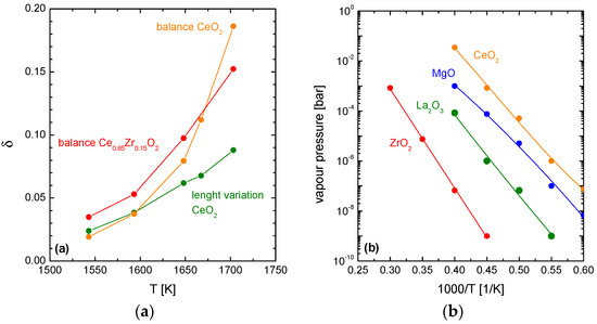
Figure 1.
(a) Calculated δ values based on chemical expansion (green) and mass loss (orange) of CeO2 [38] and mass loss of Ce0.85Zr0.15O2 (red) as a function of temperature at ptotal = 4 × 10⁻⁹ bar; (b) Vapour pressures of various oxides as a function of the reciprocal temperature [43].
On the other hand, δ can be calculated from gravimetric data (orange curve in Figure 1a)
where is the molar mass of Ce1−xMxO2, is the molar mass of oxygen, is the sample mass in the fully oxidized state and is the mass loss.
As long as the reduction temperatures are below 1600 K the calculated δ values based on chemical expansion and on the mass loss are virtually the same. Above 1600 K, however, these two δ values gradually diverge. With increasing temperatures the dilatometric data (Equation (3)) yield lower apparent δ values than the gravimetric data (Equation (4)). Thus, it can be assumed that the observed weight loss of ceria occurring at high temperatures and low pressure is not only the result of chemical reduction but is superimposed by sublimation effects. Sublimation of ceria under such conditions is obvious since the vapour pressure of ceria is high in comparison to other refractory compounds (Figure 1b).
In the present work the influence of ceria sublimation is investigated for Zr doped ceria ceramics. For that, Zr doped ceria samples (Ce0.85Zr0.15O2) were reduced under the above mentioned temperature/vacuum conditions. Based on the mass loss data, suboxide parameters δ were calculated according to Equation (4) (red curve in Figure 1a). At 1550 K and 1600 K the mass loss of Ce0.85Zr0.15O2 is somewhat higher than determined for pure CeO2 which corresponds to the beneficial effect of Zr doping in terms of thermochemical reduction. Above 1600 K, deviation between mass-derived apparent δ values of Ce0.85Zr0.15O2 and expansion-derived δ values of CeO2 gradually increases. Hence, sublimation effects at high temperatures can be assumed also for Ce0.85Zr0.15O2 compositions. At 1700 K, however, sublimation of Ce0.85Zr0.15O2 is less with respect to pure CeO2.
Ceria evaporation from Ce0.85Zr0.15O2 redox ceramics was subsequently analysed in more detail by SEM, TEM, EDS and XRD methods. Ceria evaporation from (Ce,Zr)O2 solid solutions is of particular interest since vapour pressures of CeO2 and ZrO2 are known to differ by 5 orders of magnitude [43]. Thus, it can be anticipated that evaporation of ceria gradually may go along with segregation effects. To study accelerated sublimation effects, Zr doped ceria samples (Ce0.85Zr0.15O2) were subjected to high temperature/low conditions (T = 1683 K, ptotal = 4 × 10⁻⁹ to 10−8 bar) for dwell times of 2.5 h, 5 h and 15 h.
Figure 2 and Figure 3 show SEM images and the time dependence of the thickness of the porous zone, respectively, of a Ce1−xZrxO2 sample (x = 0.15) which was reduced at 1683 K for up to 15 h at ptotal = 4 × 10⁻⁹ bar. After firing Ce0.85Zr0.15O2 samples under the aforementioned conditions obvious microstructural changes become visible: The initially polished sample has developed a spongy surface (Figure 2a). A SEM image of the cross section of the sample depicted a porous surface zone (Figure 2b). It is noteworthy that a sharp transition between the dense parent ceramic material and the porous surface zone occurs rather than a gradual transition. Surface microstructures of the Ce0.85Zr0.15O2 samples fired for 2.5 and 5 h are similar, but the thicknesses of the spongy zones are correspondingly smaller. A sublimation zone of 1 µm thickness already exists at t = 0 which is due to the fact that sublimation starts already during heating up.
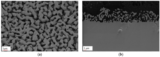
Figure 2.
(a) SEM image of the surface of a Ce1−xZrxO2 sample (x = 0.15) which was reduced at 1683 K for 15 h at ptotal = 4 × 10⁻⁹ bar; (b) SEM image of the cross section of the same sample.
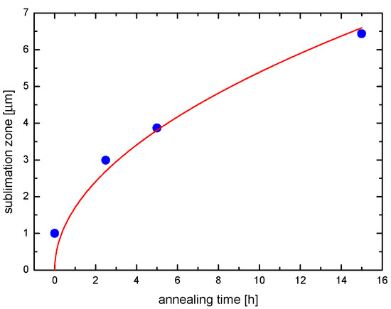
Figure 3.
Thickness of the porous surface zone of Ce1−xZrxO2 samples (x = 0.15) fired at 1683 K for different annealing times (ptotal = 4 × 10⁻⁹ bar).
Microchemical analyses of samples of 2.5 and 5 h evaporation treatments were performed by EDS analyses. According to the size of the transition region and the required spatial EDS resolution TEM-EDS was employed for the 2.5 h sample (see Figure 4) while SEM-EDS was appropriate for the later evaporation stage. Elemental mapping by TEM-EDS (Figure 4b) shows that the porous zone formed after 2.5 h heat treatment consists of 90% ZrO2 while the composition of the bulk material is virtually unaffected (85 wt % CeO2, 15 wt % ZrO2). Between the zirconia-rich spongy surface region and the unaffected bulk material a small interlayer of intermediate chemical composition (50–60% CeO2, green rim zone in Figure 4b) was detected. This composition corresponds approximately to the Ce/Zr ratio of a pyrochlore phase (Ce2Zr2O7) [17]. Sporadically, the Zr/Ce = 1:1 composition occurs also within the spongy structure.
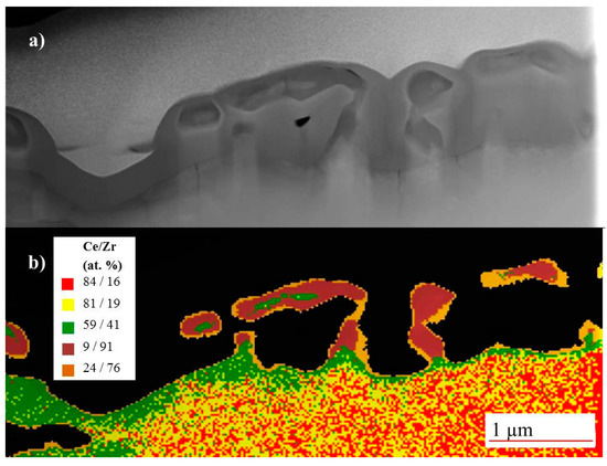
Figure 4.
(a) TEM image (FIB-ablation) of a Ce1−xZrxO2 sample sample reduced at 1683 K for 2.5 h (ptotal = 4 × 10⁻⁹ bar); (b) EDS mapping (Ce/Zr) where red = (84/16), yellow = (81/19), green = (59/41), dark red = (9/91), ochre = (24/76).
After 5 h evaporation treatment a change in chemical composition is observed (Figure 5). Still, the composition of the dense material underneath the spongy zone is unaffected. All over the porous zone, however, Ce/Zr = 1:1 composition is found without an indication of further Zr-enrichment towards the outer surface.
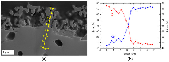
Figure 5.
(a) SEM image of a cross section of a Ce0.85Zr0.15O2−δ sample rod reduced at 1683 K for 5 h (ptotal = 4 × 10⁻⁹ bar); (b) Resulting Ce/Zr ratio of the EDS line scan along the yellow line in (a).
The data in Figure 3 suggets a kind of parabolic growth law and yields for the effective parabolic rate constant the value of k(1683 K) ≈ 4 × 10⁻¹⁶ m2/s. Taking into account the structure of this kind of constant, i.e., , with typically according to Figure 5b for an ideal CeO2–ZrO2 solid solution, it becomes obvious that the rate determining step is diffusion in the solid state with an effective diffusion coefficient , most probably indicating transport of the host cations via rapid diffusion paths (grain boundaries, interfaces) [44]. Here is the difference of the chemical potential of ceria across the porous ceria-depleted surface zone, while R and T have the usual meaning. In this approximation any pyrochlore formation has been neglected, because the resulting further decrease of the ceria activity in the outermost layer would not significantly change the order of magnitude of Deff, which is much higher than calculated cerium bulk diffusivities (see [45] and references therein).
More detailed information of newly formed phases in the porous zone was obtained by X-ray diffraction. Figure 6 shows diffraction patterns of a Ce0.85Zr0.15O2 sample fired at 1683 K for 2.5 h and 15 h (blue, black) together with the X-ray trace of the same sample after removing the porous surface zone by grinding (red) and the initial state (green). The XRD pattern after grinding unambiguously corresponds to the reduced solid solution of Ce0.85Zr0.15O2−δ while the sample after 15 h reduction, containing the spongy zone, displays additional diffraction peaks of the pyrochlore phase Ce2Zr2O7 plus faint peaks of ZrO2. In the earlier state after 2.5 h the diffraction peak assigned to the pyrochlore phase (higher diffraction angle) could be interpreted as double peak, where the peak on the right- hand side should contain a higher Zr concentration than 50 mol %. The diffraction pattern of the pyrochlore phase in general consists of a main pattern closely related to that of ceria plus additional superstructure peaks [17]. The reason for superstructure peaks is the lower symmetry of the Ce2Zr2O7 structure (space group ) with respect to (Ce,Zr)O2−δ () caused by cation and oxygen vacancy ordering (Figure 7). The main pattern of the superficial pyrochlore zone is close to the pattern of the parent Ce0.85Zr0.15O2−δ phase with a slight shift to higher diffraction angles.
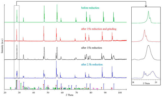
Figure 6.
XRD pattern of a Ce0.85Zr0.15O2−δ sample rod reduced at 1683 K (ptotal = 4 × 10⁻⁹ bar) for 2.5 h (blue), for 15 h (black), after grinding (red) and before reduction in comparison to theoretical pattern of ZrO2 monoclinic (ICDD PDF-00-037-1484), ZrO2 tetragonal (ICDD PDF-00-050-1089), Ce2Zr2O7 (ICDD PDF-00-034-0394 lattice constant modified: 10.7312 Å) and CeO2 (ICDD PDF-00-034-0394 lattice constant modified: 5.43839 Å).
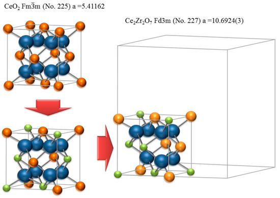
Figure 7.
The unit cell of CeO2 in comparison to 1/8 unit cell of pyrochlore Ce2Zr2O7 (blue = oxygen, green = Zr+4, ochre = Ce+4, yellow = Ce+3).
The observed surface transformation phenomena may be explained according to the following scheme (Figure 8):

Figure 8.
General scheme of the evaporation process during heating of Ce0.85Zr0.15O2−δ under low oxygen partial pressure.
Stage 1 Selective evaporation of CeO2 from Ce0.85Zr0.15O2−δ results in the formation of a highly porous surface zone very rich (≅90%) in ZrO2. The observation of superficial zirconia enrichment implies that diffusion of Ce cations from bulk to surface cannot keep up with CeO2 evaporation.
Stage 2 By interfacial reaction between the outer porous ZrO2 zone and the unaffected Ce0.85Zr0.15O2−δ parent phase an interlayer of Ce2Zr2O7 gradually forms. Early formation of a Ce2Zr2O7 interphase is frozen in (Figure 4).
Stage 3 Growth of the Ce2Zr2O7 interlayer proceeds; due to lower CeO2 activity in Ce2Zr2O7 the evaporation rate of CeO2 decreases. By that, diffusion of Ce cations from bulk to surface may keep up with CeO2 evaporation. In this stage (represented in Figure 5) the spongy surface region gradually grows without changing its composition significantly. The assumption of a gradually decreasing evaporation rate with the formation of pyrochlore Ce2Zr2O7 is also supported by the development of the mass loss curves of Ce0.85Zr0.15O2 (red curve in Figure 1a) Up to 1650 K the temperature-dependent mass loss development of Ce0.85Zr0.15O2−δ and CeO2−δ (orange curve in Figure 1a) are very similar. At higher temperature, however, when the formation of Ce2Zr2O7 can be expected, mass loss of Ce0.85Zr0.15O2 ceramics is significantly lower than for the CeO2 reference material.
In view of thermochemical water splitting by means of (Ce,Zr)O2−δ redox reactions any surface enrichment of ZrO2 by preferential evaporation of the CeO2 compound is detrimental. Though pyrochlore Ce2Zr2O7 surface composition still may facilitate the reduction step, re-oxidation by water vapour virtually can be ruled out. Thermodynamic data from Zhou et al. [7] clearly show that water splitting temperatures for (Ce,Zr)O2−δ solid solutions under equilibrium conditions gradually shift towards lower temperatures with increasing ZrO2 content. For Ce/Zr = 1/1 (pyrochlore composition) water splitting temperature is as low as 200 °C and hence will be suppressed by kinetic reasons.
4. Surface Exchange and Bulk Diffusion of Oxygen from O2 and CO2 Atmospheres
4.1. Revision of the Standard Picture of the Oxygen Exchange Kinetics
As early as 1996 Kilner et al. [46] showed that there is, for a large number of different oxide materials, a quite obvious correlation between the oxygen (tracer) surface exchange coefficient and the oxygen (tracer) diffusion coefficient (over almost 10 (!) orders of magnitude for ) for a number of perovskite compositions (with predominant electronic conductivity). Despite this empirical evidence it is assumed until to date [47,48,49], however, that and are independent parameters, each of which reflecting an independent microscopic mechanism. In Appendix A we show that this intuitive approach is not generally correct. According to the working equation derived in Appendix A (see Equation (A9)).
the experimentally accessible time constant in a thermogravimetric relaxation (TGR) experiment, , depends, for sufficiently thin sample slabs, no longer on the sample thickness, but only on the equilibrium exchange rate, , the oxygen concentration, , and the thermodynamic factor, , at the surface (). Knowing (or making an intelligent guess about) the values of and one could thus determine the key parameter directly from a simple TGR run.
To test this conclusion TGR experiments were carried out in a STA 449 F3 Jupiter system (Netzsch, Selb, Germany). Disc-shaped samples (Ø 13.4 mm, 93% theoretical density) with two different thicknesses (h1 = 1.47 mm, h2 = 0.87 mm) were prepared. The sample under investigation was placed on platinum foil on an alumina plate (Ø 15 mm).
For the reduction steps (at different high temperatures with a heating rate of 20 K/min) argon 5.0 was passed through the sample tube at a flow rate of 85 mL/min. The oxygen partial pressure of the employed gas atmosphere during the reduction step was calculated to be approximately 2 × 10⁻⁴ bar by comparing the obtained (final) suboxide compositions with literature data given by Panlener [50]. The reduction temperatures were held for several hours for complete reduction. For the subsequent oxidation step the pellet was cooled (50 K/min) to 800 °C. After a dwell time of 5 min at 800 °C an argon–oxygen gas mixture was employed for 30 min (35 mL/min O2, 50 mL/min Ar which corresponds to an oxygen partial pressure of about 0.4 bar). Subsequently, the gas was switched back to pure Ar () followed by a new reduction step. For data analysis the obtained mass loss curve was corrected by subtraction of a blank run (TG measurement without sample) to minimize device artefacts.
The results are shown in Figure 9 where the time dependence of the oxygen deficit parameter, , is plotted for a TGR experiment run at two different temperatures with two different sample thicknesses each time and the same starting difference of the chemical potential of oxygen between the gas phase and the sample. (Because of the rather short duration of the TGR experiments mass loss corrections due to evaporation were negligible.)
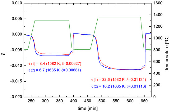
Figure 9.
Reduction (and oxidation) kinetics at 1582 K and 1635 K of two un-doped CeO2 pellets (Ø 13.4 mm, = 0.93). Red: for = 1.47 mm, = 977.055 mg. Blue: for = 0.87 mm, = 586.083 mg. Green: .
In order to facilitate understanding the following section the reader is referred to Appendix B which gives a rapid overview on the requirements which have to be fulfilled for a TGR experiment to supply valid information.
For one can use the corresponding bulk values in Equation (5), i.e., , and the thermodynamic factor can be approximated as follows with , (after [50]) and , where is the oxygen concentration in the fully oxidized state. One obtains . From Figure 9 and can be evaluated for the two samples (see Table 1), wherefrom is calculated via Equation (5) (for the reduction reaction).

Table 1.
TGR (reduction kinetics) results at two different temperatures for CeO2−δ samples with different thicknesses and different (final) values of δ.
A closer look at Table 1 reveals the following features:
- (i)
- Check of on the basis of Table B1 in Appendix B ( for surface controlled kinetics and for diffusion controlled kinetics, respectively):
This means (a) that does not depend on as for the diffusion control regime, and (b) that is confirmed with a fairly small deviation: On the basis of a 10% relative experimental error on the values, the ratio of the experimental values has an error of 20%. The negligible excess error may be due to the fact that the experiments were not yet fully surface exchange controlled but too close to the regime boundary at (see Figure A2 in Appendix A and Table B1 in Appendix B).
- (ii)
- (The experimental temperature interval (53 K) is too small to extract solid data for the activation enthalpy. The surprising behaviour of the values indicates that, however, the equilibrium exchange rate depends probably only very weakly on temperature for a given .
Summarizing, this preliminary evaluation shows that further experimental work is necessary with even thinner samples and in a larger temperature window.
4.2. Oxygen Exchange from O2 Atmospheres
The most direct method of measuring oxygen self diffusivities and surface exchange coefficients in oxides is oxygen isotope exchange followed by Secondary Ion Mass Spectrometry (SIMS) depth profiling (IEDP) [51,52,53] or cross section line scan (IELS) as is shown schematically in Figure 10. For samples with a plane sheet geometry, as used in this work, the (tracer) diffusion coefficient, , and the (tracer) surface exchange coefficient, , of oxygen are defined by
where is the oxygen tracer isotope (the 18O isotope in this work) flux through the gas/solid interface, is the concentration of the oxygen isotope in the gas phase and the actual concentration of the oxygen isotope in the solid. For a semi-infinite homogeneous plane sample the analytical solution of the diffusion problem with this boundary condition and for constant parameters K and D is given by Crank [54] (the special notation of the solution was proposed by Fielitz and Borchardt [53]).
where is the natural abundance of 18O in the sample (at ), is the diffusion length of the tracer isotope and is the characteristic time constant to reach tracer isotope equilibrium at the gas/solid interface.
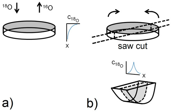
Figure 10.
Schematic diagram summarising the SIMS IEDP technique for σ < 5 µm (a) and the SIMS IELS technique for 10 µm < σ < h/4 (b). The line scan technique involves sectioning of the sample in a plane perpendicular to the exchange surface and analysing the isotope fraction profile by laterally scanning the primary ion beam across the contact line of the two exposed (half) surfaces.
The polished (diamond down to 1 µm) and cleaned (ultrasonic cleaning in acetone followed by isopropanol) samples were annealed in an IR radiation heated furnace (Quad Elliptical, RI Controls/Research Incorporated, Minneapolis, MN, USA) which allows fast heating rates up to 100 K/s in the temperature range between 300 and 900 °C. The samples were placed on a platinum mesh (avoiding contact of the platinum with the polished sample surface) in a quartz holder in well-defined atmosphere conditions (vacuum down to 10−8 bar, purified Ar gas flow with < 10−24 bar, isotope enriched gas mixture or other gas atmospheres).
The experimental work in O2 atmosphere starts with an equilibration of the samples in 0.2 bar 16O2 (natural oxygen gas) for at least 10 times the annealing time of the subsequent isotope exchange (teq = 10 × tex) in 18O2 enriched oxygen gas (96% enrichment) at the same temperature (Teq = Tex). To avoid a change in oxygen partial pressure during the first experimental step the pre-treatment is conducted in steps with renewing gas, and one of the samples is taken as a reference for measuring the actual oxygen isotope background concentration. For the second experimental step, which is the actual oxygen isotope exchange step, the samples are quenched to room temperature, the gas atmosphere is changed from 16O2 to 18O2 and the oxygen isotope exchange is then conducted at tex and Tex. Depending on the expected diffusion length of oxygen in the samples, the analysis is done either with SIMS IEDP or SIMS IELS as described in Figure 10.
Differences in sputter yield and ionisation yield can be neglected for isotopes so that the depth distribution of the atomic fraction of 18O isotopes can be quantified via
from the SIMS raw data, where I is the intensity of the SIMS signal. Figure 11 shows a typical result for a sample which was pre-annealed for teq = 5 h in 0.2 bar 16O2 at Teq = 900 °C and subsequently annealed for tex = 1800 s in 0.2 bar 18O2 at Tex = 900 °C. The resulting 18O depth profile was analysed by SIMS IELS using TOF-SIMS IV (ION-TOF GmbH, Germany). After cleaning with a Cs+ ion beam (2 keV, 143 nA) the sample was analysed with Ga+ ions (25 keV, 1.43 nA, beam size 1 µm). Sample charging was prevented by an electron flood gun. Further details are given elsewhere [55]. The background atomic fraction of oxygen isotope was measured separately on a reference sample.
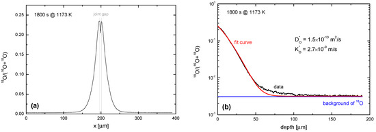
Figure 11.
SIMS line scan depth profiles measured in a nominally un-doped polycrystalline ceria sample (with 0.2 at % La) which was annealed for tex = 1800 s in 0.2 bar 18O2 gas at Tex = 1173 K in equilibrium conditions. (a) Isotope fraction of 18O perpendicular to the original surface computed by Equation (8); (b) Isotope fraction in comparison with the fit by Equation (7) and the independently measured isotope background.
Oxygen tracer diffusion coefficients in ceria containing either trivalent dopants (Gd, Sm, Y) or a tetravalent dopant (Zr), and of nominally un-doped ceria samples in the temperature range from 700 to 900 °C from experiments conducted in 0.2 bar 18O2 gas atmosphere are shown in Figure 12 together with literature data taken from [26]. Calculated activation enthalpies (numerical values in brackets) are also shown in the given temperature range of this work.
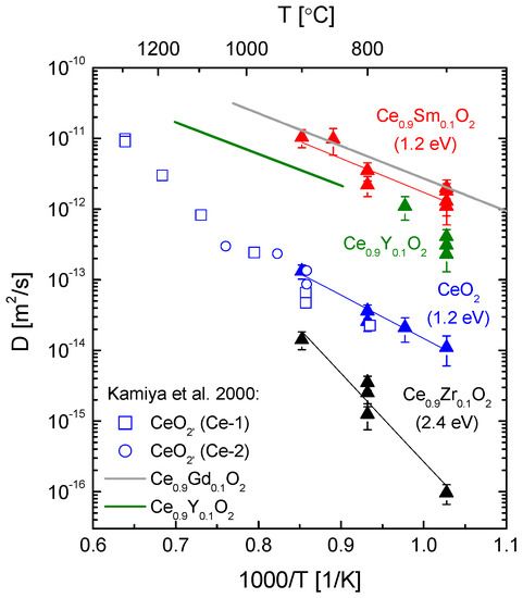
Figure 12.
Oxygen tracer diffusion coefficient (this work: data with error bars, numerical values in brackets are corresponding activation enthalpies of oxygen diffusion) in doped and nominally un-doped polycrystalline ceria (with 0.2 at % La) in the temperature range 973 to 1173 K compared with literature data taken from Kamiya et al., 2000 [26] and references therein.
Because of the lanthanum impurity in the nominally un-doped ceria samples it is reasonable to assume that the oxygen diffusion in the low temperature region T < 1000 °C is controlled by this trivalent dopant and therefore extrinsic, as was discussed by Kamiya et al. [26]. A comparison with literature data taken from [26] and references therein as shown in Figure 12 confirms a good agreement of the measured oxygen tracer diffusion coefficients of nominally un-doped ceria in the temperature range 700 °C to 900 °C in this work with data taken from [26].
The slope of the curve for nominally un-doped ceria in the Arrhenius plot in Figure 12 is small compared to the slope in the temperature range above 1000 °C, with T > 1000 °C representing the region of true intrinsic behaviour of un-doped CeO2 [26], and is similar to that of the Sm-doped ceria samples, yielding the same activation enthalpy. In the extrinsic region the experimentally obtained activation enthalpy comprises only the migration enthalpy because of the existence of extrinsic oxygen vacancies introduced by trivalent dopants. The difference in magnitude of the oxygen tracer diffusion coefficients for nominally un-doped ceria and Sm-doped ceria samples in Figure 12 is obviously partially due to the difference in the concentration of the trivalent dopant present on the cation sublattice, being 10 at % for the yttria-doped ceria samples and about 0.2 at % (La) for the nominally un-doped ceria samples.
4.3. Oxygen Exchange from CO2 Atmospheres
The global reaction for CO2 splitting on CeO2 surfaces (confer Equation (2)) is conventionally summarized in Kröger-Vink notation as follows
Depending on the experimental conditions, different reaction routes are possible, where the overall reaction path may be divided into different reaction steps. The following reaction scheme would be conceivable in accordance with the current ideas on surface exchange from pure oxygen atmosphere [56,57]
where Sad represents a CO2 adsorption site. Recent investigations revealed a high concentration and a high stability of reactive surface Ce3+ ions over a wide range of temperature and of oxygen partial pressure on ceria surfaces [58], and Ce3+ and oxygen vacancies are generally believed to be the active sites on ceria surfaces and therefore refer to the Sad adsorption sites [59,60,61].
It is generally assumed that one of the different reaction steps will be rate determining, with the charge transfer step leading to dissociation being the most likely rate determining step [56,62].
The oxygen partial pressure during experiments using a CO2 gas atmosphere is much lower in comparison to established experimental work using pure oxygen and is determined mainly by the CO/CO2 ratio of the given gas mixture as shown in Figure 13, by the respective temperature T and/or additional oxygen sources, which should be avoided. Because of the considerable cost of labelled C18O2 (835 ppm CO, <250 ppm O2, purchased from Campro Scientific GmbH, Berlin, Germany) a gas mixture with an Ar/C18O2 ratio of 10/1 (purified Ar, < 10−24 bar) in a closed volume (V ≈ 1 L) was used for the experimental work. The resulting of the CO2 containing gas mixture was less than 5 × 10⁻¹⁵ bar at T = 700 °C. Preconditioning of the samples in terms of oxygen activity was carried out in an Ar/16O2 mixture with the same oxygen partial pressure as for the isotope exchange experiments.
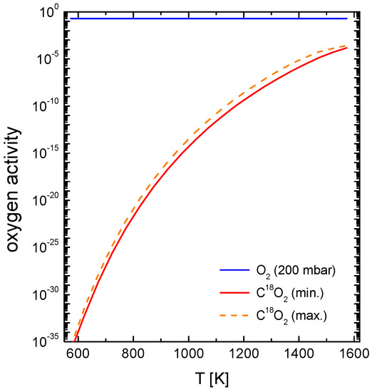
Figure 13.
Visualization of the different resulting oxygen activity values utilized in the different CO2 exchange experiments. The oxygen activity for a 0.2 bar oxygen atmosphere and for the Ar/C18O2 gas mixture was calculated with Equilib-Web [63] based on the certified gas analysis.
4.3.1. Measurements with a Chemical Potential Gradient at the Gas/Solid Interface
Comparable to the low temperature step of the two-step thermochemical cycle for splitting CO2, the experimental work utilizing a chemical potential gradient (difference in the chemical potential of oxygen) at the gas/solid interface starts with reduced (doped or un-doped) ceria samples, with the respective oxygen nonstoichiometry of the sample depending on the temperature of the reduction step and the sample type. The equilibrium oxygen activity of the samples has to be lower than the oxygen activity of the Ar/C18O2 gas mixture (as shown in Figure 14) in which the samples are annealed at a given temperature. During the experiment the 18O will be incorporated from C18O2 into the sample bulk, probably following the above mentioned reaction pathway in Equation (10). Because of the closed volume (continuous gas flow is not used due to the limited amount of labelled C18O2) the gradient of the chemical potential of oxygen will change during the experiment for two reasons. First, the oxygen activity in the sample will increase, especially at the sample surface and in the near-surface region of the bulk, due to oxygen incorporation. Second, the oxygen uptake of the samples will decrease the oxygen partial pressure in the gas phase. This is shown in Figure 14 for the reaction of reduced un-doped ceria with an Ar/C18O2 gas mixture.
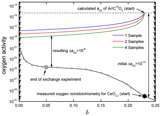
Figure 14.
Calculated change in the oxygen activity during the experiment utilizing a chemical potential gradient at the gas/solid interface at T = 700 °C when the ceria sample is initially reduced up to δ > 0.2. Experimental data is taken from reference [64] for reduced un-doped ceria at T = 715 °C. The coloured lines indicate the calculated change of the oxygen activity of the gas atmosphere for 1, 2 or 4 samples used during the oxygen exchange experiment.
The analytical solution given by Crank [54] in Equation (7) requires constant parameters D and K for the boundary conditions given in Equation (6). It can therefore only be applied if the change in the chemical potential gradient is small and the boundary condition of a constant oxygen concentration at the gas/solid interface is sufficiently fulfilled through choosing carefully the initial oxygen nonstoichiometry of the sample, i.e., initial nonstoichiometry in the flat range of the plot. When the ceria sample is initially reduced to δ ≅ 0.2, the resulting change in the chemical potential difference of oxygen, , (between the gas phase and the solid) is by a factor of about 3, and the analytical solution cannot be used with an acceptable error.
4.3.2. Measurements in Equilibrium
In contrast to the experiments with a chemical potential gradient of oxygen at the gas/solid interface, remains constant during the experiment at the given starting value shown in Figure 14. During the annealing 18O will be incorporated from C18O2 into the sample bulk, with the exchange of 16O from the sample to the C18O(ad) being the backward reaction of the reaction pathway in Equation (10). As was shown by Bueno-López et al. [65], the oxygen exchange mechanism between C18O2 and ceria samples in equilibrium consists of the exchange of oxygen atoms in two consecutive steps, yielding C16O18O and C16O2.
The challenge is the preconditioning of the samples to reach real equilibrium. The pre-treatment of the samples was done in a first so-called equilibration step utilizing an Ar/CO2 gas mixture, realizing equivalent oxygen partial pressures as given in the isotope exchange experiment and plotted in Figure 13. The resulting was measured in situ with a lambda probe.
Figure 15 shows an ion image (16O and 18O in logarithmic scale) of a 10% yttria-doped ceria sample Ce0.9Y0.1O1.95 after an oxygen isotope exchange experiment in an Ar/C18O2 gas mixture at 973 K under equilibrium conditions. The sharp line in the middle represents the joint of the juxtaposed original exchange surfaces.
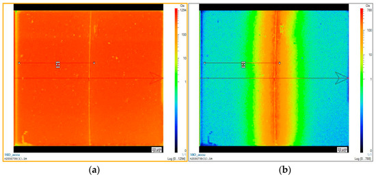
Figure 15.
Ion image for 16O (a) and 18O (b) (CAMECA 7f, GEMaC, logarithmic scale), 10% yttria-doped ceria sample Ce0.9Y0.1O1.95, oxygen isotope exchange experiment with equilibrium conditions using Ar/C18O2, T = 973 K. (Both ion images are screen shots. The blank text boxes are artefacts without physical significance. The arrow indicates the direction of the line scan half of which yielded the data for Figure 16 below.)
This ion image is used to calculate the 18O concentration along a line perpendicular to the original surface (line scan). The result is shown in Figure 16 together with the fit (analytical solution given in Equation (7)) and the resulting parameters in the inset. (The asterisk indicates a “tracer” parameter determined at chemical equilibrium between gas phase and oxide surface, i.e., . The parameters determined in an experiment with an oxygen potential gradient, i.e., , are characterized by a tilde: ).
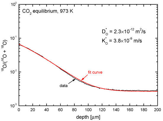
Figure 16.
Example for the 18O concentration of a 10% yttria-doped ceria sample Ce0.9Y0.1O1.95 after an oxygen isotope exchange experiment using Ar/C18O2 in equilibrium conditions at T = 973 K. Shown are the line scan SIMS measurement and the corresponding parameters and .
4.3.3. Comparison of the Oxygen Exchange Kinetics under Different Conditions
We measured the kinetic parameters of surface exchange and bulk diffusion of oxygen ( and ) in doped and nominally un-doped ceria samples (with 0.2 at % La) for three different experimental conditions at T = 973 K (see Table 2).

The resulting diffusion coefficients and exchange coefficients are shown in Figure 17. The overall trends of the diffusion coefficients (as a function of the oxygen activity in the three experimental situations on the one hand and of the nature and the concentration of the different dopants on the other hand) can be, at best, semi-quantitatively rationalized based on the respective total oxygen vacancy concentration (see Figure 17a). With the exception of Zr-doped ceria, a similar trend, though less directly evident, is observed for the exchange coefficient (see Figure 17b).
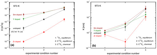
Figure 17.
Graphical compilation of (a) measured oxygen diffusion coefficients, ; and (b) oxygen surface exchange coefficients, , at 973 K in nominally un-doped ceria (0.2 at % La) and doped ceria samples (trivalent or tetravalent doping with 10% Sm, Y, Zr) under three different experimental conditions (see Table 2). The dashed lines are drawn as a guide for the eye.
As all the discussed isotope exchange experiments were performed in the mixed control regime or in the diffusion control regime (see Figure A2 in Appendix A) the obtained parameters K and D are not independent, which suggests that the alternative approach developed in Appendix A should be employed. Before doing this the reader is referred to the so-called critical length, D/K, which is shown in Figure 18a for three different experimental conditions (see Table 2) at 973 K. However, this is only another merely descriptive parameter ratio for technical applications, which is not well suited for more profound interpretation. (The exact role of the platinum support was neither an objective nor could it be quantified in the framework of our investigations. According to recent literature data a ceria surface traps about 1 Pt atom/nm2 in oxidizing ambient conditions [66]. Anyhow Figure 18b shows in accordance with literature data [65], that, at elevated temperatures, a potential Pt effect is no longer dominant and obviously also depends on the dopant.)
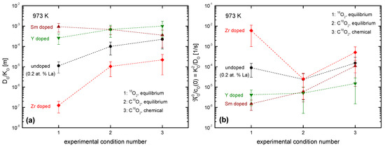
Figure 18.
Graphical compilation of derived parameters from measured K-D data: (a) critical length, (b) normalized equilibrium rate constant (see text for the meaning of the derived parameters) for three different experimental conditions (see Table 2) at 973 K. For the evaluation of these derived parameters the K-D data shown in Figure 17 were used.
For a deeper understanding, the normalized equilibrium rate constant has to be evaluated via Equation (A4) in Appendix A. For , it reads for “thick” samples . The normalized equilibrium exchange rate constant is thus identical with the reciprocal characteristic time constant to reach (isotope) equilibrium at the surface as discussed above in the context of Equation (7). The resulting plot in Figure 18b reflects obvious dependencies on doping and oxygen activity, which can be qualitatively interpreted with the aid of an expression for in the case of charge transfer as the rate determining step in the oxygen incorporation (confer [34,56]), which reads
(Regarding the different quantities in the master Equation (11) the reader is referred to Equation (A6) in Appendix A.) For the experimental condition #1 ( both in the gas phase and in the solid) decreases with increasing concentration of the trivalent dopant while Zr seems to neutralize the La contamination. For the experimental condition #2 ( both in the gas phase and in the solid) increases strongly for the Zr doped material, but less for the trivalent-doped material and thus causes a strong decrease in for the Zr-doped material, and no big change for the trivalent-doped material. For the experimental conditions #3 the discussion is less straightforward. Here the solid is equilibrated to while the gas phase has a (starting) oxygen activity . For the time being more experimental information is needed and an interpretation on the basis of Equation (11) would be premature.
5. Conclusions
Redox studies on zirconia-doped ceria revealed selective sublimation of ceria from ceria–zirconia solid solutions when reduction temperatures are above 1600 K and gas pressures were low. As a consequence surface segregation of zirconia occurs in (Ce,Zr)O2−δ pellets and a porous surface zone of Ce2Zr2O7 pyrochlore is observed which gradually grows in thickness. Surface enrichment of zirconia is detrimental for splitting CO2 or H2O since re-oxidation temperatures of (Ce,Zr)O2−δ are known to be shifted towards lower temperatures with increasing ZrO2 content. Thus, very harsh reduction conditions should be avoided for the (Ce,Zr)O2−δ redox system.
The kinetics investigations focus on the oxygen exchange and diffusion during the high temperature reduction steps (T ≈ 1600 K) and on the respective kinetics of the “low” temperature (T ≅ 1000 K) oxidation reaction with a carbon dioxide atmosphere. Based on a recent extension of the current phenomenological treatment of the exchange kinetics by the present authors, the thermogravimetric analyses of the reduction kinetics (at around 1600 K and an oxygen activity of 7 × 10⁻⁴ in the gas phase) directly yield the (reduction) equilibrium exchange rate of oxygen in the order of 10−7 mol·O/(cm3·s) as the kinetics are surface controlled. The oxidation step at around 1000 K, however, occurs in the mixed control or in the diffusion control regime, respectively. Here, oxygen isotope exchange in combination with SIMS depth profiling is the method of choice for pure oxygen atmosphere and carbon dioxide atmosphere, both labelled with 18O. With this tracer technique oxygen exchange coefficients, K, and oxygen diffusivities, D, were determined for so-called equilibrium experiments as well as for non-equilibrium measurements . From the experimentally observed values for K and D the (oxidation) equilibrium exchange rates for differently doped ceria samples were determined. Their dependency on the oxygen activity and the nature and the concentrations of a tetravalent dopant (Zr) and trivalent dopants (La, Y, Sm) can be semi-quantitatively rationalised on the basis of a master equation for the equilibrium surface exchange rate. (In our study, the potential role of Pt traces on the numerical value of the oxygen exchange rate could not be addressed. It seems that this is implicitly true for most of the published studies on oxygen surface exchange kinetics at high temperatures. But the influence of platinum seems to decrease with increasing temperatures [65] and the exchange rate then mostly depends on the very nature of the surface, i.e., on the dopants.)
Acknowledgments
Financial support by the Initiative and Networking Fund of the Helmholtz Association of German Research Centers within the Virtual Institute SolarSynGas as well as by Deutsche Forschungsgemeinschaft (DFG) for one of the authors (P.F.) is gratefully acknowledged. Thanks to the Schöne Familienstiftung a PhD student (D.U.) could be partially funded. We are indebted to M. Schulz, F. Jomard and C. Argirusis for some SIMS line scans and to S. Fischer for technical assistance with the sample preparation. R. Pitz-Paal and M. Roeb very efficiently steered the research work of the Virtual Institute. Constructive criticism of anonymous reviewers helped to improve the manuscript.
Author Contributions
Nicole Knoblauch: sample preparation, thermogravimetric and dilatometric studies; Heike Simon: TEM investigations; Lars Dörrer: design and construction of the oxygen isotope exchange apparatus, SIMS-IEDP analyses; Daniel Uxa: performance of the oxygen exchange experiments in 18O2 and C18O2 atmospheres; Stefan Beschnitt: performance of SIMS line scans; Peter Fielitz: kinetics data evaluation and interpretation, text assembling; Jens Wendelstorf: thermodynamic calculations; Karl-Heinz Spitzer: computer simulations of kinetic parameters; Martin Schmücker: SEM investigations, data interpretation, text composition; Günter Borchardt: physico-chemical discussion of the results, text composition.
Conflicts of Interest
The authors declare no conflict of interest.
Appendix A
A major reason for the conventional assumption that the oxygen exchange coefficient and the oxygen diffusivity are independent parameters can be identified in the methodology of standard oxygen exchange experiments [52]: Here the oxygen flux through a surface element subject to an oxygen concentration difference is expressed as follows
The phenomenological Equation (A1) defines without recurring to any microscopic mechanism.
Figure A1 schematically represents a gas/oxide interface of a homogeneous semi-infinite solid oxide. D is the self-diffusion coefficient of oxygen ions () in the solid oxide, p is oxygen partial pressure () in the gas phase and R is the equilibrium oxygen exchange rate () at the interface. At a small step-like change δµ (0) of the chemical potential of oxygen () is experimentally induced at the gas/oxide interface at . As Equation (A1) is only valid for surface reactions at it seemed plausible that depends exclusively on the defect chemistry of the surface. As we will see below, this assumption is not generally correct either.
In 1998 Maier [32] proposed a relation between and the equilibrium oxygen exchange rate at the gas/solid interface (see Maier [32], page 222, Equation (149))
where is the oxygen equilibrium concentration near the surface, is the thermodynamic factor near the surface, R and T have the usual meaning, and is the chemical potential of oxygen. is the equilibrium oxygen exchange rate of the rate determining step in a consecutive reaction sequence [56,67]. The quantitative measure of the parameter (with the dimension of a length) having been left undefined, Maier’s suggestion essentially means that is proportional to [68].
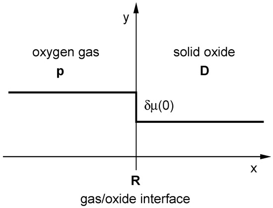
Figure A1.
Schematic representation of a gas/oxide interface of a homogeneous semi-infinite solid oxide (see text for the meaning of the symbols).
The relation between the oxygen exchange coefficient in an equilibrium experiment, , and in the corresponding non-equilibrium exchange experiment, , reads . From , where is the self-diffusion coefficient and is the tracer diffusion coefficient of oxygen, respectively, follows with the correlation factor a simple relation [68]
Throughout the text an asterisk characterizes a parameter determined in an isotope exchange experiment, whereas a tilde refers to a parameter determined in a chemical exchange experiment. Whenever this distinction is irrelevant on theoretical grounds the specification is omitted.
In 2006 De Souza [56] explicitly pointed out that there is a generally observed discrepancy between experimentally determined ratios and the theoretically expected ratios according to Equation (A3). Instead of fulfilling Equation (A3) the experimental data yield . This was a first significant experimental indication that the consequences resulting from Equation (A2) might not fully cover all aspects of the problem.
Armstrong et al. [29,69] used in 2011 and 2013 a novel experimental approach, called isothermal isotope exchange (IIE), to extract accurate values in a surface exchange controlled regime. Very unexpectedly Armstrong et al. [29,69] found apparent activation energies of with negative (!) or very small positive values for different lanthanum based MIEC perovskite oxides, but also for the standard oxygen ion conductors YSZ and GDC, which have fluorite structure. The reported range of apparent activation energies of the oxygen tracer surface exchange coefficient is −97 kJ/mol to +12 kJ/mol and is in strong contrast to the reported range from +60 kJ/mol to +333 kJ/mol measured by conventional methods generally using macroscopic sample geometries, i.e., IEDP/SIMS and electrical conductivity relaxation (ECR) (see Table 5 in Armstrong et al. [69]). These experimental results suggest that the measured oxygen surface exchange coefficient , if measured in the mixed controlled regime and in the diffusion controlled regime, may depend not only on the equilibrium oxygen exchange rate at the gas/solid interface but also on the oxygen diffusion coefficient in the bulk. Such a behaviour would clearly contradict Equation (A2) which postulates that depends on only in all kinetic regimes.
In our earlier joint work on nominally un-doped ceria [33] we also observed a vanishing apparent activation energy of the chemical oxygen surface exchange coefficient in the surface exchange controlled regime.
Summarising one has the following experimental contradictions to the consequences of Equations (A2) and (A3):
- (a)
- Kilner’s correlation [46]:
- (b)
- De Souza’s conclusion [56]:
- (c)
- Armstrong et al. [29,69] (for ) and Knoblauch et al. [33] (for ) found very low values for the activation energy of the surface exchange coefficient in the true surface exchange controlled regime.
For the necessary revision of the existing theoretical approach according to Maier et al. [32,68] we expanded Maier's treatment and included diffusional transport in the bulk. Thus coupling surface exchange to subsequent transport in the bulk we could recently [34] explain the discrepancies (a) through (c).
For (a) and (c): If the TGR samples are sufficiently thick (thickness ) the diffusion controlled regime with (see Figure A2) is valid. As shown in detail in [34] the exchange coefficient becomes
This means that Kilner’s data compilation [46] comprises only experiments performed in the diffusion controlled regime. The authors’ conclusion that their empirical correlation for the activation enthalpies (for ) and (for ), which is [46], has a sound physical basis, would be only true if and , but especially , were no material specific parameters and if all three of them would not depend on temperature at all—which is not the case. According to Equation (A4) the activation energy of is, however, the mean value of the individual activation energies of and .
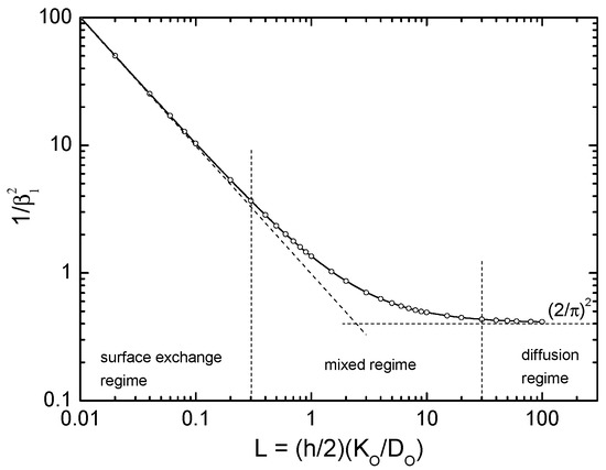
Figure A2.
Graphical visualisation of the kinetic regimens [33] (open points are positive roots of tabulated by Carslaw and Jaeger [70]). The diffusion controlled regime is characterised by and the surface exchange controlled regime by .
In the true surface exchange controlled regime () one gets for sufficiently thin samples [34]
In this case the activation energy is presumably much smaller. Because of the complex structure of the equilibrium exchange rate [34]
it could be very small or even formally negative within the usual error range of experimental activation energy values. Here are the rate constants of the forward and of the backward reaction, respectively, of the rate determining step (rds), are the mass law constants of the (oxygen) adsorption and of the (oxygen) incorporation step, respectively; stand for the oxygen concentration, the electron and the defect electron concentration and for the oxygen vacancy concentration, respectively.
For (b): In [34] we derive a generally valid relation between the tracer parameters and the chemical parameters :
(Here is the structural correlation factor). As for oxides the reason for the discrepancy between Maier’s result [32] and De Souza’s conclusion [56] becomes evident: Instead of Equation (A3), Equation (A7) has to be used.
In a TGR experiment performed in the surface controlled regime the experimentally accessible time constant is
With from Equation (A5), no longer depends on the sample thickness , and the equilibrium exchange rate becomes
Appendix B
One direct way to follow the kinetics of oxygen uptake or release in situ at high temperatures is a gravimetric experiment [33]. For plate-like samples with thickness and with both large faces in contact with the atmosphere the mass change, , if normalized to the mass change at equilibrium, , is given by Crank [54] (page 60)
The dimensionless quantities are positive roots of . As the infinite sum in Equation (B1) converges rapidly one gets approximately [33]
where, strictly speaking, is the chemical diffusion coefficient of oxygen in the solid and is the corresponding surface exchange coefficient of oxygen defined by Equation (A1) in Appendix A. Both parameters are assumed constant in the experimental range, which means that the difference in the chemical potential of oxygen, , between the O2 gas atmosphere and the oxide sample should be tolerably “small” (which, however, depends on the defect thermodynamics of the mass transport in the bulk).
The relevant positive roots of are plotted in Figure A2 which allows a graphical visualisation of the kinetic regimes. The values of the resulting dimensionless parameters of the kinetic regimes are compiled in Table B1.

Table B1.
Characteristic parameters of the kinetic regimes.
Table B1.
Characteristic parameters of the kinetic regimes.
| Kinetic Regime | |||||
|---|---|---|---|---|---|
| Surface Controlled | 1 | ||||
| Mixed Regime | |||||
| Diffusion Regime |
If possible, any TGR experiment should be run either unambiguously in the surface controlled regime or clearly in the diffusion controlled regime in order to enable a sound theoretical interpretation of the obtained values of . For experiments carried on in a mixed controlled regime the interpretation is less easy as it requires more theoretical information as described in Appendix A.
References
- Abanades, S.; Flamant, G. Thermochemical hydrogen production from a two-step solar-driven water-splitting cycle based on cerium oxides. Sol. Energy 2006, 80, 1611–1623. [Google Scholar] [CrossRef]
- Ackermann, S.; Scheffe, J.R.; Steinfeld, A. Diffusion of Oxygen in Ceria at Elevated Temperatures and Its Application to H2O/CO2 Splitting. J. Phys. Chem. C 2014, 118, 5216–5225. [Google Scholar] [CrossRef]
- Bulfin, B.; Lowe, A.J.; Keogh, K.A.; Murphy, B.E.; Lübben, O.; Krasnikov, S.A.; Shvets, I.V. Analytical Model of CeO2 Oxidation and Reduction. J. Phys. Chem. C 2013, 117, 24129–24137. [Google Scholar] [CrossRef]
- Chueh, W.C.; Haile, S.M. A thermochemical study of ceria: Exploiting an old material for new modes of energy conversion and CO2 mitigation. Philos. Trans. R. Soc. A Math. Phys. Eng. Sci. 2010, 368, 3269–3294. [Google Scholar] [CrossRef] [PubMed]
- Zhou, G.; Shah, P.R.; Montini, T.; Fornasiero, P.; Gorte, R.J. Oxidation enthalpies for reduction of ceria surfaces. Surf. Sci. 2007, 601, 2512–2519. [Google Scholar] [CrossRef]
- Shah, P.R.; Kim, T.; Zhou, G.; Fornasiero, P.; Gorte, R.J. Evidence for Entropy Effects in the Reduction of Ceria–Zirconia Solutions. Chem. Mater. 2006, 18, 5363–5369. [Google Scholar] [CrossRef]
- Zhou, G.; Shah, P.R.; Kim, T.; Fornasiero, P.; Gorte, R.J. Oxidation entropies and enthalpies of ceria–zirconia solid solutions. Catal. Today 2007, 123, 86–93. [Google Scholar] [CrossRef]
- Kim, T.; Vohs, J.M.; Gorte, R.J. Thermodynamic Investigation of the Redox Properties of Ceria–Zirconia Solid Solutions. Ind. Eng. Chem. Res. 2006, 45, 5561–5565. [Google Scholar] [CrossRef]
- Bulfin, B.; Hoffmann, L.; Oliveira, L.; Knoblauch, N.; Call, F.; Roeb, M.; Sattler, C.; Schmücker, M. Statistical thermodynamics of non-stoichiometric ceria and ceria zirconia solid solutions. Phys. Chem. Chem. Phys. 2016, 18, 23147–23154. [Google Scholar] [CrossRef] [PubMed]
- Kuhn, M.; Bishop, S.R.; Rupp, J.L.M.; Tuller, H.L. Structural characterization and oxygen nonstoichiometry of ceria–zirconia (Ce1−xZrxO2−δ) solid solutions. Acta Mater. 2013, 61, 4277–4288. [Google Scholar] [CrossRef]
- Hao, Y.; Yang, C.-K.; Haile, S.M. Ceria–Zirconia Solid Solutions (Ce1–xZrxO2−δ, x ≤ 0.2) for Solar Thermochemical Water Splitting: A Thermodynamic Study. Chem. Mater. 2014, 26, 6073–6082. [Google Scholar] [CrossRef]
- Takacs, M.; Scheffe, J.R.; Steinfeld, A. Oxygen nonstoichiometry and thermodynamic characterization of Zr doped ceria in the 1573–1773 K temperature range. Phys. Chem. Chem. Phys. 2015, 17, 7813–7822. [Google Scholar] [CrossRef] [PubMed]
- Huang, S.; Li, L.; Van der Biest, O.; Vleugels, J. Influence of the oxygen partial pressure on the reduction of CeO2 and CeO2–ZrO2 ceramics. Solid State Sci. 2005, 7, 539–544. [Google Scholar] [CrossRef]
- Huang, S.; Li, L.; Vleugels, J.; Wang, P.; Van der Biest, O. Thermodynamic prediction of the nonstoichiometric phase Zr1–zCezO2–x in the ZrO2–CeO1.5–CeO2 system. J. Eur. Ceram. Soc. 2003, 23, 99–106. [Google Scholar] [CrossRef]
- Sanjuan, M.L.; Oliete, P.B.; Varez, A.; Sanz, J. The role of Ce reduction in the segregation of metastable phases in the ZrO2–CeO2 system. J. Eur. Ceram. Soc. 2012, 32, 689–696. [Google Scholar] [CrossRef]
- Montini, T.; Banares, M.A.; Hickey, N.; Di Monte, R.; Fornasiero, P.; Kaspar, J.; Graziani, M. Promotion of reduction in Ce0.5Zr0.5O2: The pyrochlore structure as effect rather than cause? Phys. Chem. Chem. Phys. 2004, 6, 1–3. [Google Scholar] [CrossRef]
- Achary, N.S.; Sali, S.K.; Kulkarni, N.K.; Krishna, P.S.R.; Shinde, A.B.; Tyagi, A.K. Intercalation/Deintercalation of Oxygen: A Sequential Evolution of Phases in Ce2O3/CeO2−ZrO2 Pyrochlores. Chem. Mater. 2009, 21, 5848–5859. [Google Scholar] [CrossRef]
- Conesa, J.C. Computer Modeling of Local Level Structures in (Ce, Zr) Mixed Oxide. J. Phys. Chem. B 2003, 107, 8840–8853. [Google Scholar] [CrossRef]
- Wang, H.-F.; Guo, Y.-L.; Lu, G.-Z.; Hu, P. Maximizing the Localized Relaxation: The Origin of the Outstanding Oxygen Storage Capacity of κ-Ce2Zr2O8. Angew. Chem. Int. Ed. 2009, 48, 8289–8292. [Google Scholar] [CrossRef] [PubMed]
- Montini, T.; Hickey, N.; Fornasiero, P.; Graziani, M.; Bañares, M.A.; Martinez-Huerta, M.; Alessandri, I.; Depero, L.E. Variations in the Extent of Pyrochlore-Type Cation Ordering in Ce2Zr2O8: A t′−κ Pathway to Low-Temperature Reduction. Chem. Mater. 2005, 17, 1157–1166. [Google Scholar] [CrossRef]
- Pérez-Omil, J.A.; Bernal, S.; Calvino, J.J.; Hernández, J.C.; Mira, C.; Rodríguez-Luque, M.P.; Erni, R.; Browning, N.D. Combined HREM and HAADF Scanning Transmission Electron Microscopy: A Powerful Tool for Investigating Structural Changes in Thermally Aged Ceria−Zirconia Mixed Oxides. Chem. Mater. 2005, 17, 4282–4285. [Google Scholar] [CrossRef]
- Bunluesin, T.; Gorte, R.J.; Graham, G.W. CO oxidation for the characterization of reducibility in oxygen storage components of three-way automotive catalysts. Appl. Catal. B 1997, 14, 105–115. [Google Scholar] [CrossRef]
- Gorte, R.J. Ceria in catalysis: From automotive applications to the water–gas shift reaction. AIChE J. 2010, 56, 1126–1135. [Google Scholar] [CrossRef]
- Scheffe, J.R.; Steinfeld, A. Thermodynamic Analysis of Cerium-Based Oxides for Solar Thermochemical Fuel Production. Energy Fuels 2012, 26, 1928–1936. [Google Scholar] [CrossRef]
- Manning, P.S.; Sirman, J.D.; Kilner, J.A. Oxygen self-diffusion and surface exchange studies electrolytes having the fluorite structure of oxide. Solid State Ion. 1997, 93, 125–132. [Google Scholar] [CrossRef]
- Kamiya, M.; Shimada, E.; Ikuma, Y.; Komatsu, M.; Haneda, H. Intrinsic and Extrinsic Oxygen Diffusion and Surface Exchange Reaction in Cerium Oxide. J. Electrochem. Soc. 2000, 147, 1222–1227. [Google Scholar] [CrossRef]
- Katsuki, M.; Wang, S.; Yasumoto, K.; Dokiya, M. The oxygen transport in Gd-doped ceria. Solid State Ion. 2002, 154–155, 589–595. [Google Scholar] [CrossRef]
- Stan, M.; Zhu, Y.T.; Jiang, H. Kinetics of oxygen removal from ceria. J. Appl. Phys. 2004, 95, 3358–3361. [Google Scholar] [CrossRef]
- Armstrong, E.N.; Duncan, K.L.; Oh, D.J.; Weaver, J.F.; Wachsman, E.D. Determination of Surface Exchange Coefficients of LSM, LSCF, YSZ, GDC Constituent Materials in Composite SOFC Cathodes. J. Electrochem. Soc. 2011, 158, B492–B499. [Google Scholar] [CrossRef]
- Gopal, C.B.; Haile, S.M. An electrical conductivity relaxation study of oxygen transport in samarium doped ceria. J. Mater. Chem. A 2014, 2, 2405–2417. [Google Scholar] [CrossRef]
- Rutman, J.; Kilo, M.; Weber, S.; Riess, I. Tracer surface exchange and diffusion of oxygen in nano crystals of Gd doped CeO2. Solid State Ion. 2014, 265, 29–37. [Google Scholar] [CrossRef]
- Maier, J. On the correlation of macroscopic and microscopic rate constants in solid state chemistry. Solid State Ion. 1998, 112, 197–228. [Google Scholar] [CrossRef]
- Knoblauch, N.; Dörrer, L.; Fielitz, P.; Schmücker, M.; Borchardt, G. Surface controlled reduction kinetics of nominally un-doped polycrystalline CeO2. Phys. Chem. Chem. Phys. 2015, 17, 5849–5860. [Google Scholar] [CrossRef] [PubMed]
- Fielitz, P.; Borchardt, G. Oxygen exchange at gas/oxide interfaces: How the apparent activation energy of the surface exchange coefficient depends on the kinetic regime. Phys. Chem. Chem. Phys. 2016, 18, 22031–22038. [Google Scholar] [CrossRef] [PubMed]
- Rührup, V.; Wiemhöfer, H. Ionic Conductivity of Gd- and Y-Doped Ceria–Zirconia Solid Solutions. Z. Naturforsch. 2006, 61b, 916–922. [Google Scholar] [CrossRef]
- Ji, H.-I.; Davenport, T.C.; Gopal, C.B.; Haile, S.M. Extreme high temperature redox kinetics in ceria: Exploration of the transition from gas-phase to material-kinetic limitations. Phys. Chem. Chem. Phys. 2016, 18, 21554–21561. [Google Scholar] [CrossRef] [PubMed]
- Pechini, M.P. Method of Preparing Lead and Alkaline Earth Titanates and Niobates and Coating Method Using the Same to form a Capacitor. U.S. Patent 3.330.697, 11 July 1967. [Google Scholar]
- Knoblauch, N.; Simon, H.; Schmücker, M. Chemically induced volume change of CeO2−δ and nonstoichiometric phases. Solid State Ion. 2017, 301, 43–52. [Google Scholar] [CrossRef]
- Ahrens, L.H. The use of ionization potentials Part 1. Ionic radii of the elements. Geochim. Cosmochim. Acta 1952, 2, 155–169. [Google Scholar] [CrossRef]
- Bishop, S.R. Chemical expansion of solid oxide fuel cell materials: A brief overview. Acta Mech. Sin. 2013, 29, 312–317. [Google Scholar] [CrossRef]
- Marrocchelli, D.; Bishop, S.R.; Tuller, H.L.; Yildiz, B. Understanding Chemical Expansion in Non-Stoichiometric Oxides: Ceria and Zirconia Case Studies. Adv. Funct. Mater. 2012, 22, 1958–1965. [Google Scholar] [CrossRef]
- Hull, S.; Norberg, S.T.; Ahmed, I.; Eriksson, S.G.; Marrocchelli, D.; Madden, P.A. Oxygen vacancy ordering within anion-deficient Ceria. J. Solid State Chem. 2009, 182, 2815–2821. [Google Scholar] [CrossRef]
- Schulz, U.; Saruhan, B.; Fritscher, K.; Leyens, C. Review on Advanced EB-PVD Ceramic Topcoats for TBC Applications. Int. J. Appl. Ceram. Technol. 2004, 1, 302–315. [Google Scholar] [CrossRef]
- Chen, P.L.; Chen, I.W. Role of Defect Interaction in Boundary Mobility and Cation Diffusivity of CeO2. J. Am. Ceram. Soc. 1994, 77, 2289–2297. [Google Scholar] [CrossRef]
- Beschnitt, S.; Zacherle, T.; De Souza, R.A. Computational Study of Cation Diffusion in Ceria. J. Phys. Chem. C 2015, 119, 27307–27315. [Google Scholar] [CrossRef]
- Kilner, J.A.; De Souza, R.A.; Fullarton, I.C. Surface exchange of oxygen in mixed conducting perovskite oxides. Solid State Ion. 1996, 86–88, 703–709. [Google Scholar] [CrossRef]
- Kilner, J.A.; Skinner, S.J.; Brongersma, H.H. The isotope exchange depth profiling (IEDP) technique using SIMS and LEIS. J. Solid State Electrochem. 2011, 15, 861–876. [Google Scholar] [CrossRef]
- Blair, J.; Mebane, D.S. A Bayesian approach to electrical conductivity relaxation and isotope exchange/secondary ion mass spectrometry. Solid State Ion. 2015, 270, 47–53. [Google Scholar] [CrossRef]
- Ananyev, M.V.; Tropin, E.S.; Eremin, V.A.; Farlenkov, A.S.; Smirnov, A.S.; Kolchugin, A.A.; Porotnikova, N.M.; Khodimchuk, A.V.; Berenov, A.V.; Kurumchin, E.K. Oxygen isotope exchange in La2NiO4±δ. Phys. Chem. Chem. Phys. 2016, 18, 9102–9111. [Google Scholar] [CrossRef] [PubMed]
- Panlener, R.J.; Blumenthal, R.N.; Garnier, J.E. A Thermodynamic Study of Nonstoichiometric Cerium Dioxide. J. Phys. Chem. Solids 1975, 36, 1213–1222. [Google Scholar] [CrossRef]
- Kilner, J.A.; Steele, B.C.H. Oxygen self-diffusion studies using negative-ion secondary ion mass spectrometry (SIMS). Solid State Ion. 1984, 12, 89–97. [Google Scholar] [CrossRef]
- Chater, R.J.; Carter, S.; Kilner, J.A.; Steele, B.C.H. Development of a novel SIMS technique for oxygen self-diffusion and surface exchange coefficient measurements in oxides of high diffusivity. Solid State Ion. 1992, 53–56, 859–867. [Google Scholar] [CrossRef]
- Fielitz, P.; Borchardt, G. On the accurate measurement of oxygen self-diffusivities and surface exchange coefficients in oxides via SIMS depth profiling. Solid State Ion. 2001, 144, 71–80. [Google Scholar] [CrossRef]
- Crank, J. The Mathematics of Diffusion, 2nd ed.; Oxford University Press: Oxford, UK, 1975. [Google Scholar]
- De Souza, R.A.; Zehnpfenning, J.; Martin, M.; Maier, J. Determining oxygen isotope profiles in oxides with Time-of-Flight SIMS. Solid State Ion. 2005, 176, 1465–1471. [Google Scholar] [CrossRef]
- De Souza, R.A. A universal empirical expression for the isotope surface exchange coefficients (k*) of acceptor-doped perovskite and fluorite oxides. Phys. Chem. Chem. Phys. 2006, 8, 890–897. [Google Scholar] [CrossRef] [PubMed]
- Boukamp, B.A.; van Hassel, B.A.; Vinke, I.C.; de Vries, K.J.; Burggraaf, A.J. The Oxygen transfer process on oxide/noble metal electrodes, studied with impedance spectroscopy, DC polarization and isotope exchange. Electrochem. Acta 1993, 38, 1817–1825. [Google Scholar] [CrossRef]
- Chueh, W.C.; McDaniel, A.H.; Grass, M.E.; Hao, Y.; Jabeen, N.; Liu, Z.; Haile, S.M.; McCarty, K.F.; Bluhm, H.; El Gabaly, F. Highly Enhanced Concentration and Stability of Reactive Ce3+ on Doped CeO2 Surface Revealed In Operando. Chem. Mater. 2012, 24, 1876–1882. [Google Scholar] [CrossRef]
- Murugan, B.; Ramaswamy, A.V. Defect-Site Promoted Surface Reorganization in Nanocrystalline Ceria for the Low-Temperature Activation of Ethylbenzene. J. Am. Chem. Soc. 2007, 129, 3062–3063. [Google Scholar] [CrossRef] [PubMed]
- Nolan, M.; Parker, S.C.; Watson, G.W. CeO2 catalysed conversion of CO, NO2 and NO from first principles energetics. Phys. Chem. Chem. Phys. 2006, 8, 216–218. [Google Scholar] [CrossRef] [PubMed]
- Sayle, T.X.T.; Parker, S.C.; Catlow, R.A. Surface Oxygen Vacancy Formation on CeO2 and Its Role in the Oxidation of Carbon Monoxide. J. Chem. Soc. Chem. Commun. 1992, 977–978. [Google Scholar] [CrossRef]
- Fleig, J. On the current–voltage characteristics of charge transfer reactions at mixed conducting electrodes on solid electrolytes. Phys. Chem. Chem. Phys. 2005, 7, 2027–2037. [Google Scholar] [CrossRef] [PubMed]
- Bale, C.W.; Bélisle, E. Available online: http://www.crct.polymtl.ca/equiweb.php (accessed on 7 August 2016).
- Bevan, D.J.M.; Kordis, J. Mixed Oxides Of The Type MO2(Fluorite)–M2O3—I Oxygen Dissociation Pressures And Phase Relationships In The System CeO2–Ce2O3 At High Temperatures. J. Inorg. Nucl. Chem. 1964, 26, 1509–1523. [Google Scholar] [CrossRef]
- Bueno-López, A.; Krishna, K.; Makkee, M. Oxygen exchange mechanism between isotopic CO2 and Pt/CeO2. Appl. Catal. A Gen. 2008, 342, 144–149. [Google Scholar] [CrossRef]
- Jones, J.; Xiong, H.; DeLaRiva, A.T.; Peterson, E.J.; Pham, H.; Challa, S.R.; Qi, G.; Oh, S.; Wiebenga, M.H.; Hernández, X.I.P.; et al. Thermally stable single-atom platinum-on-ceria catalysts via atom trapping. Science 2016, 353, 150–154. [Google Scholar] [CrossRef] [PubMed]
- Merkle, R.; Maier, J. How Is Oxygen Incorporated into Oxides? A Comprehensive Kinetic Study of a Simple Solid-State Reaction with SrTiO3 as a Model Material. Angew. Chem. Int. Ed. 2008, 47, 3874–3894. [Google Scholar] [CrossRef] [PubMed]
- Maier, J. Interaction of oxygen with oxides: How to interpret measured effective rate constants? Solid State Ion. 2000, 135, 575–588. [Google Scholar] [CrossRef]
- Armstrong, E.N.; Duncan, K.L.; Wachsman, E.D. Effect of A and B-site cations on surface exchange coefficient for ABO3 perovskite materials. Phys. Chem. Chem. Phys. 2013, 15, 2298–2308. [Google Scholar] [CrossRef] [PubMed]
- Carslaw, H.S.; Jaeger, J.C. Conduction of Heat in Solids, 2nd ed.; Clarendon Press: Wotton-under-Edge, UK, 1959. [Google Scholar]
© 2017 by the authors. Licensee MDPI, Basel, Switzerland. This article is an open access article distributed under the terms and conditions of the Creative Commons Attribution (CC BY) license (http://creativecommons.org/licenses/by/4.0/).