
Synthesis of Titanium Dioxide Photoanodes by Anodization in a Sodium Chloride Electrolyte


Abstract

1. Introduction
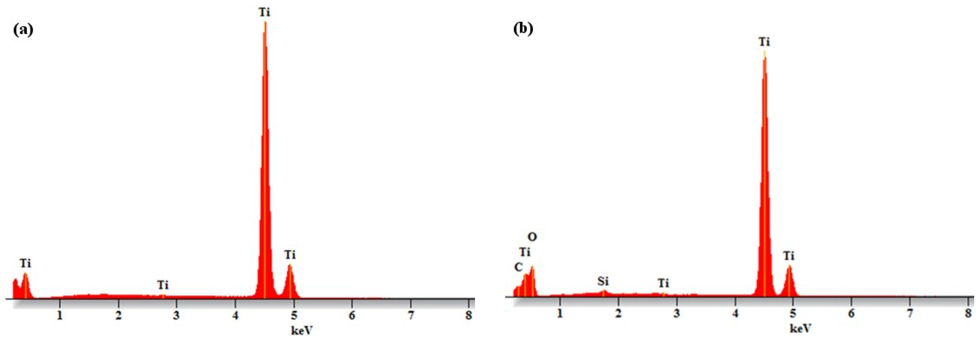
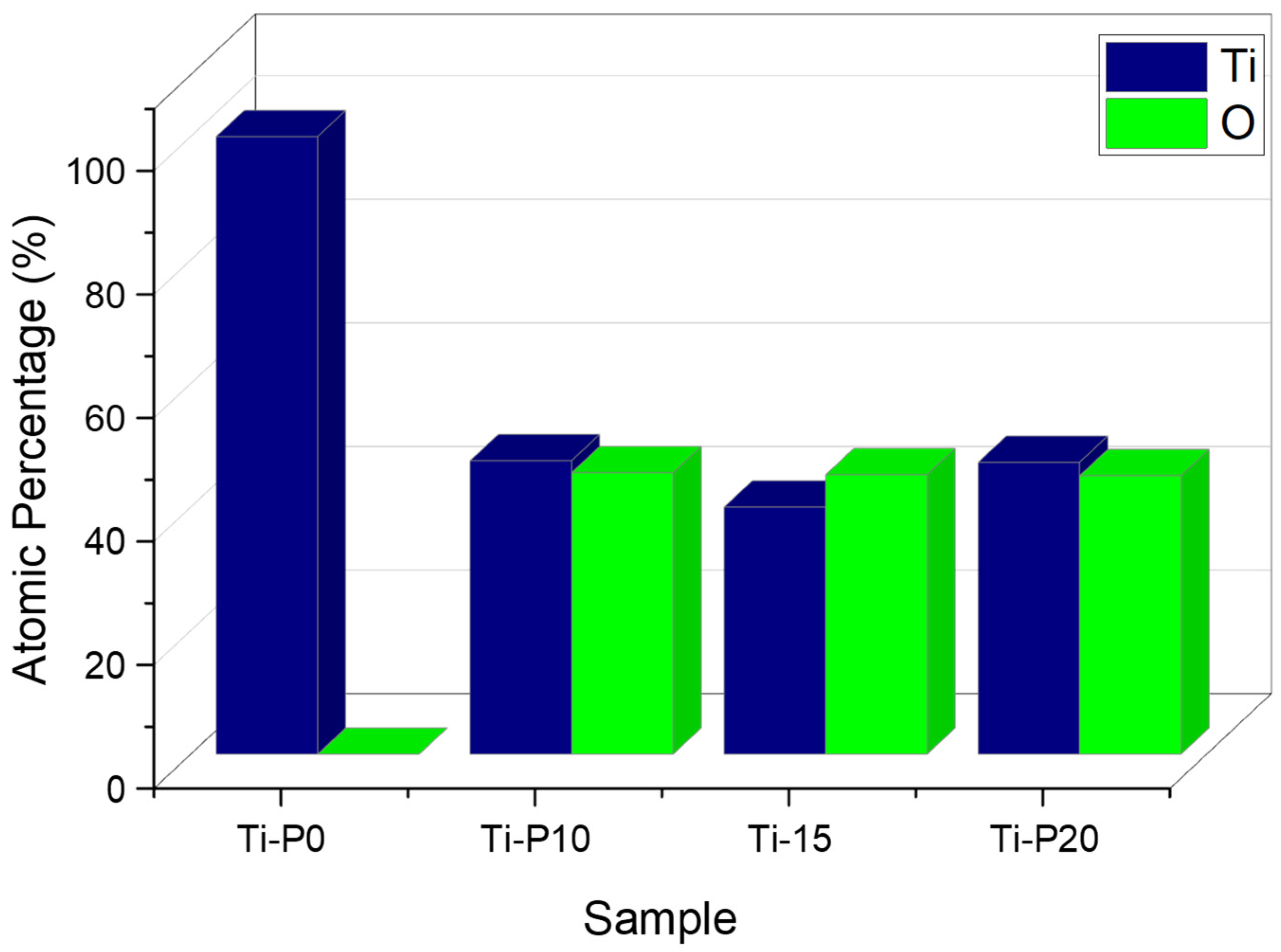
2. Results and Discussion
3. Materials and Methods
3.1. Electrochemical Anodization
3.2. Characterization
4. Conclusions
Supplementary Materials
Author Contributions
Funding
Institutional Review Board Statement
Data Availability Statement
Acknowledgments
Conflicts of Interest
References
- Akira, F.; Kenichi, H. Fujishima-Electrochemical photolysis of water at semiconductor electrode. Nature 1972, 238, 37–38. [Google Scholar]
- Bestetti, M.; Sacco, D.; Brunella, M.F.; Franz, S.; Amadelli, R.; Samiolo, L. Photocatalytic degradation activity of titanium dioxide sol-gel coatings on stainless steel wire meshes. Mater. Chem. Phys. 2010, 124, 1225–1231. [Google Scholar] [CrossRef]
- Song, R.; Chi, H.; Ma, Q.; Li, D.; Wang, X.; Gao, W.; Wang, H.; Wang, X.; Li, Z.; Li, C. Highly Efficient Degradation of Persistent Pollutants with 3D Nanocone TiO2-Based Photoelectrocatalysis. J. Am. Chem. Soc. 2021, 143, 13664–13674. [Google Scholar] [CrossRef]
- Ravidhas, C.; Anitha, B.; Arivukarasan, D.; Venkatesh, R.; Christy, A.J.; Jothivenkatachalam, K.; Nithya, A.; Raj, A.M.E.; Ravichandran, K. Tunable morphology with selective faceted growth of visible light active TiO2 thin films by facile hydrothermal method: Structural, optical and photocatalytic properties. J. Mater. Sci. Mater. Electron. 2016, 27, 5020–5032. [Google Scholar] [CrossRef]
- Nyamukamba, P.; Okoh, O.; Mungondori, H.; Taziwa, R.; Zinya, S. Synthetic Methods for Titanium Dioxide Nanoparticles: A Review. In Titanium Dioxide—Material for a Sustainable Environment; Yang, D., Ed.; InTech: Takasago, Japan, 2018. [Google Scholar]
- Ghorbani, A.B.; Neda, G.; Vahabzade, P.J.; Ebrahimian, P.A. Boosting the photoconversion efficiency of TiO2 nanotubes using UV radiation-assisted anodization as a prospective method: An efficient photocatalyst for eliminating resistant organic pollutants. Ceram. Int. 2020, 46, 19942–19951. [Google Scholar]
- Yang, F.; Feng, X.; Ge, F.; Zhang, T.; Qi, J.; Li, D.; Zhu, X. Rapid growth of titanium oxide nanotubes under the critical breakdown voltage: Evidence against the dissolution reaction of fluoride ions. Electrochem. Commun. 2019, 103, 17–21. [Google Scholar] [CrossRef]
- Juang, Y.; Liu, Y.; Nurhayati, E.; Thuy, N.T.; Huang, C.; Hu, C.C. Anodic fabrication of advanced titania nanotubes photocatalysts for photoelectrocatalysis decolorization of Orange G dye. Chemosphere 2016, 144, 2462–2468. [Google Scholar] [CrossRef]
- Bestetti, M.; Franz, S.; Cuzzolin, M.; Arosio, P.; Cavallotti, P.L. Structure of nanotubular titanium oxide templates prepared by electrochemical anodization in H2SO4/HF solutions. Thin Solid Film. 2007, 515, 5253–5258. [Google Scholar] [CrossRef]
- Hassan, F.M.B.; Nanjo, H.; Venkatachalam, S.; Kanakubo, M.; Ebina, T. Effect of the solvent on growth of titania nanotubes prepared by anodization of Ti in HCl. Electrochim. Acta 2010, 55, 3130–3137. [Google Scholar] [CrossRef]
- Allam, N.K.; Shankar, K.; Grimes, C.A. Photoelectrochemical and water photoelectrolysis properties of ordered TiO2 nanotubes fabricated by Ti anodization in fluoride-free HCl electrolytes. J. Mater. Chem. 2008, 18, 2341–2348. [Google Scholar] [CrossRef]
- Ng, S.W.; Yam, F.K.; Beh, K.P.; Hassan, Z. Titanium Dioxide Nanotubes in Chloride Based Electrolyte: An Alternative to Fluoride Based Electrolyte. Sains Malays. 2014, 43, 947–951. [Google Scholar]
- Nguyen, Q.A.; Bhargava, Y.V.; Devine, T.M. Titania nanotube formation in chloride and bromide containing electrolytes. Electrochem. Commun. 2008, 10, 471–475. [Google Scholar] [CrossRef]
- Hahn, R.; Macak, J.M.; Schmuki, P. Rapid anodic growth of TiO2 and WO3 nanotubes in fluoride free electrolytes. Electrochem. Commun. 2007, 9, 947–952. [Google Scholar] [CrossRef]
- Cheong, Y.L.; Yam, F.K.; Ng, S.W.; Hassan, Z.; Ng, S.S.; Low, I.M. Fabrication of titanium dioxide nanotubes in fluoride-free electrolyte via rapid breakdown anodization. J. Porous Mater. 2015, 22, 1437–1444. [Google Scholar] [CrossRef]
- Richter, C.; Panaitescu, E.; Willey, R.; Menon, L. Titania nanotubes prepared by anodization in fluorine-free acids. J. Mater. Res. 2007, 22, 1624–1631. [Google Scholar] [CrossRef]
- Durdu, S.; Cihan, G.; Yalcin, E.; Altinkok, A. Characterization and mechanical properties of TiO2 nanotubes formed on titanium by anodic oxidation. Ceram. Int. 2021, 47, 10972–10979. [Google Scholar] [CrossRef]
- Li, P.; Qin, L.; Chen, B.; Zhang, S.; Zhu, Y.; Wang, B.; Zhu, X. The role of fluoride and phosphate anions in the formation of anodic titanium dioxide nanotubes. Electrochem. Commun. 2024, 158, 107641. [Google Scholar] [CrossRef]
- Fahim, N.F.; Sekino, T.; Morks, M.F.; Kusunose, T. Electrochemical growth of vertically-oriented high aspect ratio titania nanotubes by rabid anodization in fluoride-free media. J. Nanosci. Nanotechnol. 2009, 9, 1803–1818. [Google Scholar] [CrossRef]
- Shukla, G.; Kumar, C.; Angappane, S. Structural Properties and Wettability of TiO2 Nanorods. Phys. Status Solidi B Basic Solid State Phys. 2019, 256, 1900032. [Google Scholar] [CrossRef]
- Thamaphat, K.; Limsuwan, P.; Ngotawornchai, B. Phase Characterization of TiO2 Powder by XRD and TEM. Agric. Nat. Resour. 2008, 42, 357–361. [Google Scholar]
- Addala, S.; Bouhdjer, L.; Chala, A.; Bouhdjar, A.; Halimi, O.; Boudine, B.; Sebais, M. Structural and optical properties of a NaCl single crystal doped with CuO nanocrystals. Chin. Phys. B 2013, 22, 098103. [Google Scholar] [CrossRef]
- Smith, Y.R.; Sarma, B.; Mohanty, S.K.; Misra, M. Light-assisted anodized TiO2 nanotube arrays. ACS Appl. Mater. Interfaces 2012, 4, 5883–5890. [Google Scholar] [CrossRef] [PubMed]
- Mahalakshmi, M.; Arabindoo, B.; Palanichamy, M.; Murugesan, V. Preparation, characterization, and photocatalytic activity of Gd3+ doped TiO2 nanoparticles. J. Nanosci. Nanotechnol. 2007, 7, 3277–3285. [Google Scholar] [CrossRef] [PubMed]
- Gombac, V.; De Rogatis, L.; Gasparotto, A.; Vicario, G.; Montini, T.; Barreca, D.; Balducci, G.; Fornasiero, P.; Tondello, E.; Graziani, M. TiO2 nanopowders doped with boron and nitrogen for photocatalytic applications. Chem. Phys. 2007, 339, 111–123. [Google Scholar] [CrossRef]
- Ben Chobba, M.; Messaoud, M.; Weththimuni, M.L.; Bouaziz, J.; Licchelli, M.; De Leo, F.; Urzì, C. Preparation and characterization of photocatalytic Gd-doped TiO2 nanoparticles for water treatment. Environ. Sci. Pollut. Res. 2019, 26, 32734–32745. [Google Scholar] [CrossRef]


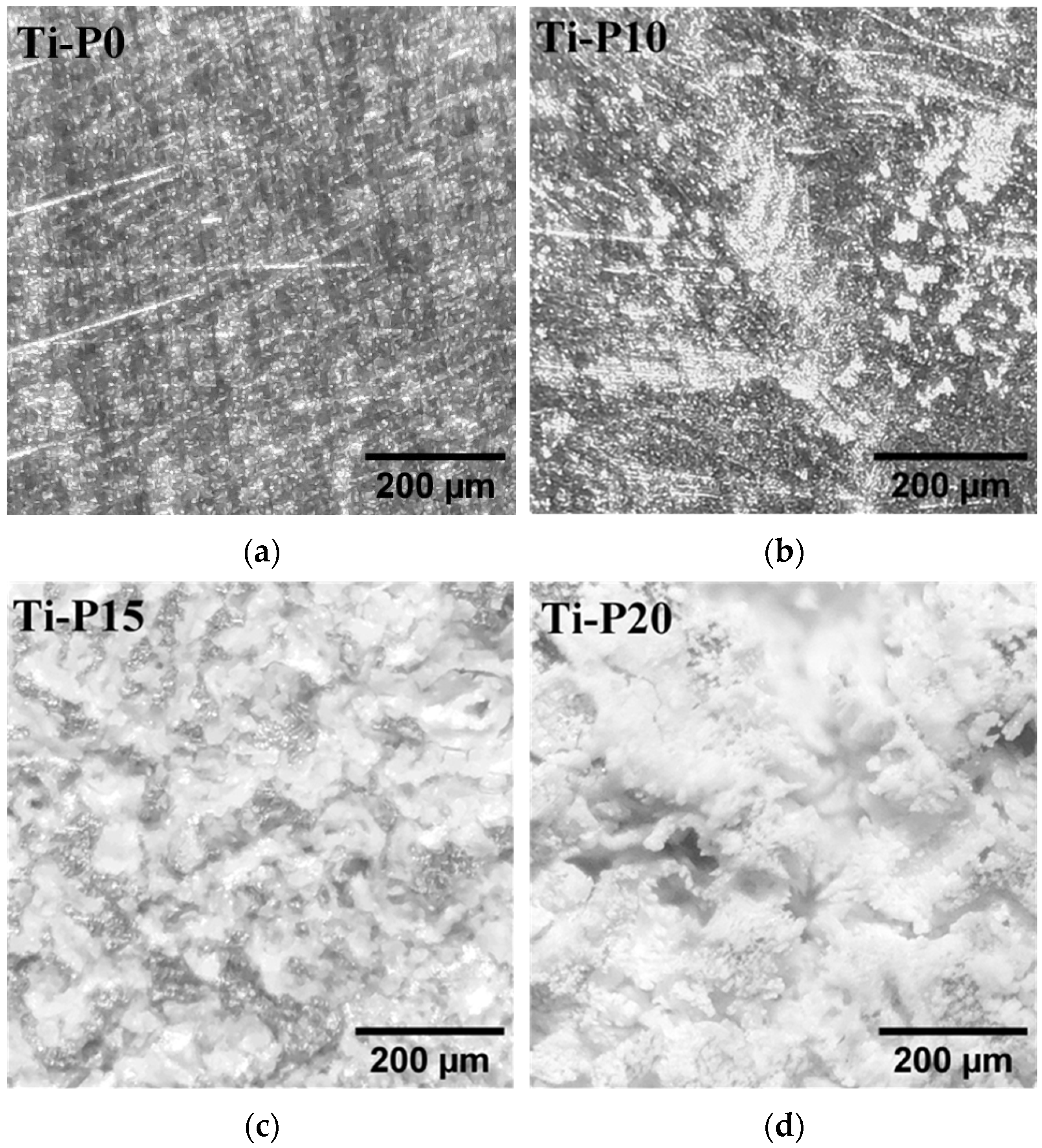
| Sample | RMS Roughness (sq) |
|---|---|
| Ti-P0 | 51.72 nm |
| Ti-P10 | 125.8 nm |
| Ti-P15 | 53.02 nm |
| Ti-P20 | 79.09 nm |
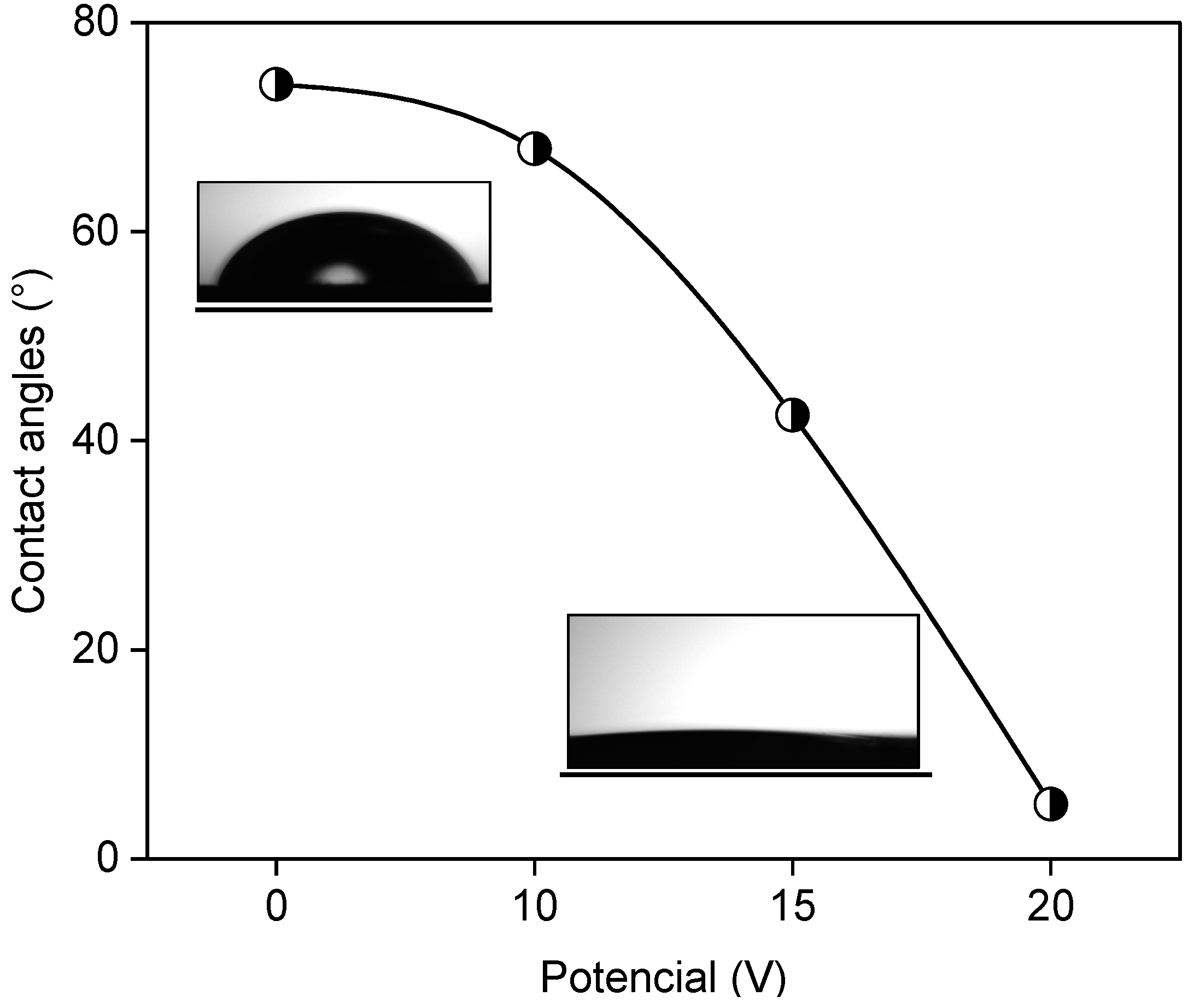
| Sample | Contact Angles (°) |
|---|---|
| Ti-P0 | 74 |
| Ti-P10 | 67 |
| Ti-P15 | 42 |
| Ti-P20 | 5 |
| Raman Signals (cm−1) | Crystalline Phase |
|---|---|
| 139.6 | Anatase [24,25,26] |
| 393.4 | Anatase [3,24,25,26] |
| 513 | Anatase [24,25,26] |
| 639 | Anatase [3,24,25,26] |
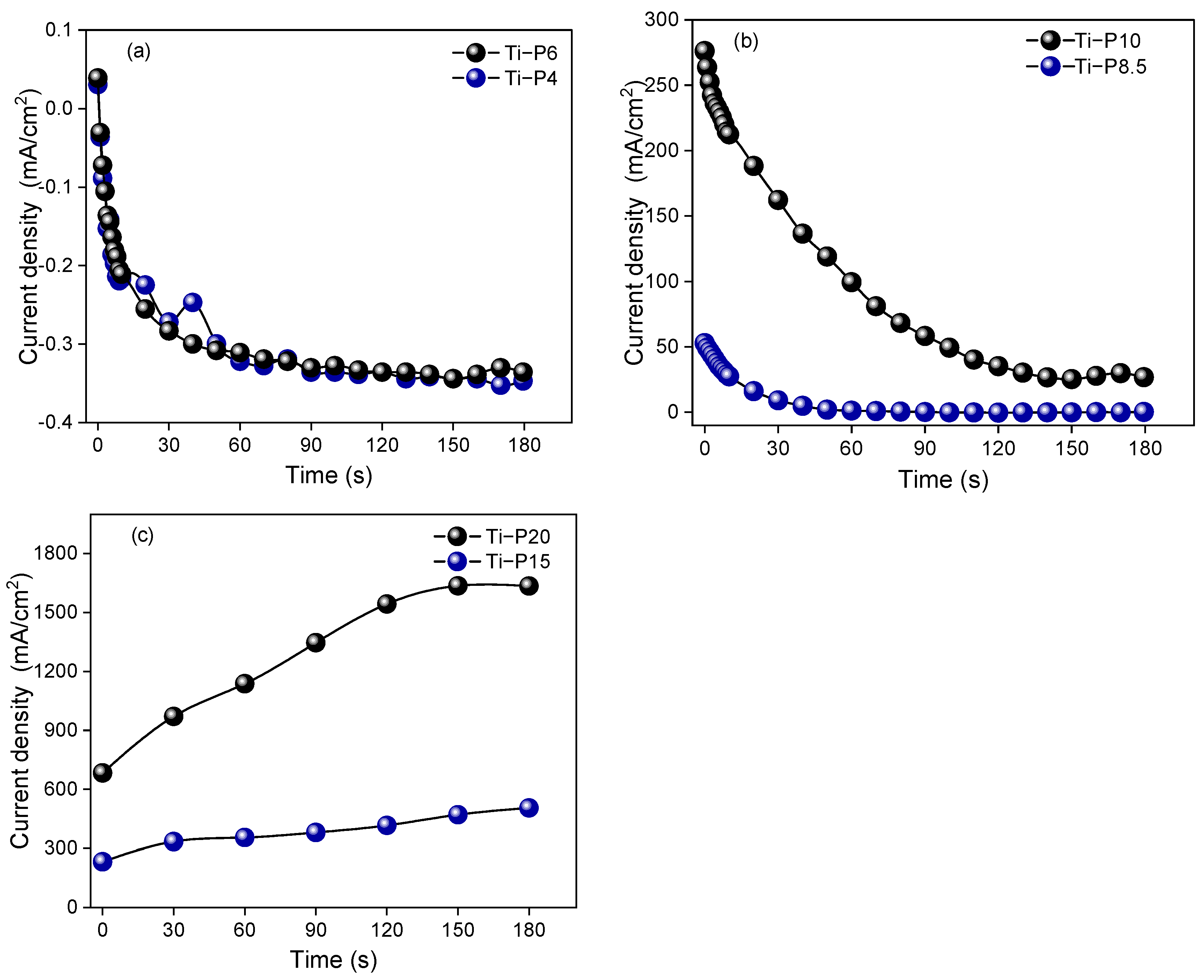
| Anodizing Potential | Samples |
|---|---|
| 0 volts | Ti-P0 |
| 4 volts | Ti-P4 |
| 6 volts | Ti-P6 |
| 8.5 volts | Ti-P8.5 |
| 10 volts | Ti-P10 |
| 15 volts | Ti-P15 |
| 20 volts | Ti-P20 |
Disclaimer/Publisher’s Note: The statements, opinions and data contained in all publications are solely those of the individual author(s) and contributor(s) and not of MDPI and/or the editor(s). MDPI and/or the editor(s) disclaim responsibility for any injury to people or property resulting from any ideas, methods, instructions or products referred to in the content. |
© 2025 by the authors. Licensee MDPI, Basel, Switzerland. This article is an open access article distributed under the terms and conditions of the Creative Commons Attribution (CC BY) license (https://creativecommons.org/licenses/by/4.0/).
Share and Cite
Del Angel-Hernández, B.; Martínez-Orozco, R.D.; García-Alamilla, R.; Torre, A.I.R.d.l.; Terrés, E.; Páramo-García, U. Synthesis of Titanium Dioxide Photoanodes by Anodization in a Sodium Chloride Electrolyte. Inorganics 2025, 13, 133. https://doi.org/10.3390/inorganics13050133
Del Angel-Hernández B, Martínez-Orozco RD, García-Alamilla R, Torre AIRdl, Terrés E, Páramo-García U. Synthesis of Titanium Dioxide Photoanodes by Anodization in a Sodium Chloride Electrolyte. Inorganics. 2025; 13(5):133. https://doi.org/10.3390/inorganics13050133
Chicago/Turabian StyleDel Angel-Hernández, Briseyda, Reinaldo David Martínez-Orozco, Ricardo García-Alamilla, Adriana Isabel Reyes de la Torre, E. Terrés, and Ulises Páramo-García. 2025. "Synthesis of Titanium Dioxide Photoanodes by Anodization in a Sodium Chloride Electrolyte" Inorganics 13, no. 5: 133. https://doi.org/10.3390/inorganics13050133
APA StyleDel Angel-Hernández, B., Martínez-Orozco, R. D., García-Alamilla, R., Torre, A. I. R. d. l., Terrés, E., & Páramo-García, U. (2025). Synthesis of Titanium Dioxide Photoanodes by Anodization in a Sodium Chloride Electrolyte. Inorganics, 13(5), 133. https://doi.org/10.3390/inorganics13050133